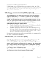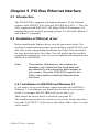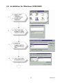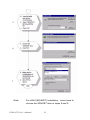
1
PCM-9578
Socket 370
Celeron™/Pentium® III SBC with
4 Ethernet, CFC and GPIO
Users’ Manual
Copyright
This document is copyrighted, © 2003. All rights are reserved. The original manufacturer reserves the right to make improvements to the products
described in this manual at any time without notice.
No part of this manual may be reproduced, copied, translated or transmitted in any form or by any means without the prior written permission of
the original manufacturer. Information provided in this manual is
intended to be accurate and reliable. However, the original manufacturer
assumes no responsibility for its use, nor for any infringements upon the
rights of third parties that may result from such use.
Acknowledgements
IBM, PC/AT, PS/2 and VGA are trademarks of International Business
Machines Corporation.
Intel and StrongARM are trademarks of Intel Corporation.
Microsoft Windows® CE.NET is a registered trademark of Microsoft
Corp.
All other product names or trademarks are properties of their respective
owners.
For more information on this and other Advantech products, please visit
our websites at:
http://www.advantech.com
http://www.advantech.com/epc
For technical support and service, please visit our support website at:
http://support.advantech.com
This manual is for the PCM-9578F, rev. A1.
Part No. 2006957810
1st Edition: January, 2003
PCM-9578 User’s Manual
ii
Packing List
Before you begin installing your card, please make sure that the following
materials have been shipped:
• 1 PCM-9578F all-in-one single board computer
• 1 CD disc with utility and drivers
• 1 Startup Manual
• 1 mini jumper package [10 pcs] (p/n: 9689000002)
• 1 EBX 7P - 4P power cable
If any of these items are missing or damaged, contact your distributor or
sales representative immediately.
Please refer to Appendix C for the optional interface wiring kit.
Additional Information and Assistance
Step 1. Visit the Advantech web site at www.advantech.com/risc where
you can find the latest information about the product.
Step 2. Contact your distributor, sales representative, or Advantech's customer service center for technical support if you need additional
assistance. Please have the following information ready before
you call:
• Product name and serial number
• Description of your peripheral attachments
• Description of your software (operating system, version, application
software, etc.)
• A complete description of the problem
• The exact wording of any error messages
iii
PCM-9578 User’s Manual
iv
Contents
Chapter
1 General Information ........................................2
1.1
1.2
1.3
1.4
Introduction ....................................................................... 2
Features ............................................................................. 3
Specifications .................................................................... 3
Dimensions and Board Layout.......................................... 5
Figure 1.1:PCM-9578 dimensions.................................. 5
Chapter
2 Installation ........................................................8
2.1
Jumpers.............................................................................. 8
2.2
Connectors......................................................................... 9
2.3
Locating Jumpers ............................................................ 10
2.4
Locating Connectors ....................................................... 11
Table 2.1:Jumpers........................................................... 8
Table 2.2:Connectors on the PCM-9578 ........................ 9
Figure 2.1:Locating Jumpers ........................................ 10
Figure 2.2:Locating Connectors (component side)....... 11
Figure 2.3:Locating Connectors (solder side)............... 12
2.5
2.6
Setting Jumpers ............................................................... 13
CPU installation and upgrading ...................................... 14
2.6.1
2.6.2
2.7
Installing DRAM (SODIMMs) ....................................... 15
2.7.1
2.7.2
2.8
Connecting the hard drive............................................. 16
Floppy drive connector (CN14, optional) ....................... 17
2.9.1
2.10
2.11
2.12
Introduction................................................................... 15
Installing SODIMMs .................................................... 16
IDE Hard Drive Connector (CN8) .................................. 16
2.8.1
2.9
Installing a CPU in the ZIF socket................................ 14
CMOS clear (J4) ........................................................... 15
Table 2.3:CMOS clear (J4)........................................... 15
Connecting the floppy drive ......................................... 17
Parallel port connector (CN9) ......................................... 17
Keyboard and PS/2 mouse connector (CN11) ................ 18
Power & HDD indicator LED connector (CN4)............. 18
2.12.1 Reset switch .................................................................. 18
2.13
Power connectors (CN1, CN10, CN25, CN29) .............. 18
2.13.1 Main power connector, +5 V, +12 V (CN29)............... 18
2.13.2 Fan power connector (CN1, CN10, CN25, CN7)......... 18
2.14
ATX power control connector (CN22, CN23)................ 19
2.14.1 ATX feature conn (CN23) & power button (CN22)..... 19
Figure 2.4:Wiring for ATX power switch function...... 19
2.15
2.16
COM-port connector (CN13, CN16) .............................. 20
VGA interface connections (CN18)................................ 20
v
2.17
Ethernet configuration..................................................... 20
2.17.1 100Base-T connector (CN1, CN4, CN5)...................... 20
2.17.2 Network boot ................................................................ 20
2.18
2.19
2.20
Chapter
Ethernet 3, Ethernet 4 bypass function............................ 21
USB connectors (CN12).................................................. 21
Digital I/O (CN5) ............................................................ 21
3 Award BIOS Setup.........................................24
3.1
System test and initialization........................................... 24
3.1.1
3.2
System configuration verification................................. 24
Award BIOS setup .......................................................... 24
3.2.1
Entering setup ............................................................... 25
Figure 3.1:Setup program initial screen........................ 25
3.2.2 Standard CMOS setup .................................................. 26
Figure 3.2:CMOS setup screen..................................... 26
3.2.3 BIOS features setup ...................................................... 27
Figure 3.3:BIOS features setup..................................... 27
3.2.4 Chipset features setup ................................................... 28
Figure 3.4:Chipset features setup.................................. 28
3.2.5 Power management setup ............................................. 29
Figure 3.5:Power management setup............................ 29
3.2.6 PnP/PCI configuration .................................................. 30
Figure 3.6: PnP/PCI configuration................................ 30
3.2.7 Integrated peripherals ................................................... 31
Figure 3.7:Integrated peripherals.................................. 31
3.2.8 Load BIOS defaults ...................................................... 32
Figure 3.8:Load BIOS defaults..................................... 32
3.2.9 Change password .......................................................... 33
3.2.10 Auto detect hard disk .................................................... 34
Figure 3.9:IDE HDD auto detection screen.................. 34
3.2.11 Save & exit setup .......................................................... 34
3.2.12 Exit without saving ....................................................... 34
Chapter
4 AGP SVGA Setup ..........................................36
4.1
Introduction ..................................................................... 36
4.1.1
4.1.2
4.1.3
4.2
4.3
4.4
4.5
Chipset .......................................................................... 36
Display types................................................................. 36
Dual/simultaneous display............................................ 36
Figure 4.1:Selecting display settings ............................ 37
Installation of SVGA driver ............................................ 37
Installation for Windows 98 and 2000 ............................ 38
Installation for Windows NT........................................... 43
Further information ......................................................... 47
PCM-9578 User’s Manual
vi
Chapter
5 PCI Bus Ethernet Interface...........................50
5.1
5.2
Introduction ..................................................................... 50
Installation of Ethernet driver ......................................... 50
5.2.1
5.3
5.4
5.5
Installation for MS-DOS and Windows 3.1.................. 50
Installation for Windows 95/98/2000.............................. 51
Installation for Windows NT........................................... 53
Further information ......................................................... 55
Appendix A Pin Assignments .............................................58
A.1
A.2
A.3
A.4
A.5
A.6
A.8
A.9
A.10
A.11
A.12
A.13
A.14
A.15
A.16
Ethernet 10/100Base-T (CN26, CN24, CN20, CN17)... 58
ATX Power Feature Connector (CN23) ..................... 58
Keyboard and PS/2 Mouse Connector (CN11) ............... 59
Main Power Connector (CN29) ...................................... 60
Floppy Disk Drive Connector (CN14) ............................ 61
IDE Hard Drive Connector (CN8) ................................. 62
CRT Display Connector (CN18)..................................... 64
Power & HDD LED Connector(CN4) ............................ 64
USB Connector (CN12) .................................................. 65
Serial Port 1 connector DB-9 (CN13) ............................. 66
Serial Port 2 connector (CN16)....................................... 66
CompactFlash™ Card Connector (CN30) .................... 67
CPU fan power connector (CN10, CN1) ........................ 68
System fan power connector (CN25) .............................. 68
Fan failure LED (CN7) ................................................... 68
Appendix B System Assignments .......................................70
B.1
B.2
B.3
B.4
System I/O Ports.............................................................. 70
1st MB memory map....................................................... 71
DMA channel assignments.............................................. 71
Interrupt assignments ...................................................... 72
Appendix C Optional Extras ..............................................74
C.1
PCM-10586-5E cable kit for PCM-9578 ........................ 74
Appendix D Mechanical Drawings.....................................76
D.1
D.2
Component Side .............................................................. 76
Solder Side ...................................................................... 77
vii
PCM-9578 User’s Manual
viii
CHAPTER
1
General Information
This chapter gives background
information on the PCM-9578.
Sections include:
• Introduction
• Features
• Specifications
• Board layout and dimensions
Chapter 1 General Information
1.1 Introduction
The PCM-9578F is an all-in-one Celeron™Pentium® III level single
board computer (SBC) with quadruple Ethernet interfaces, 2 COM, 8
GPIO and one PCI expansion slot. The PCM-9578F supports Pentium III
(Tualatin) processors up to 1.26 GHz. It has an optional LAN3/LAN4
bypass function. This compact unit is only 203 x 146 mm (8" x 5.75"). It
offers all the functions of a single board industrial computer, but still fits
in the space of a 5.25" CD ROM drive, and 1 U chassis for the networking appliance market.
On-board features include two serial ports, one multi-mode parallel
(ECP/EPP/SPP) port, two USB (Universal Serial Bus) ports, one CompactFlash socket for CFC, and a keyboard/PS/2 mouse interface. The
built-in high-speed PCI IDE controller supports PIO, UDMA/33 and bus
master modes. Up to two IDE devices can be connected, including large
hard disks, CD-ROM drives and tape backup drives.
The PCM-9578F features power management to minimize power consumption. It complies with the “Green Function” standard and supports
doze, standby and suspend modes. In addition, the boardís watchdog
timer can automatically reset the system or generate an interrupt in case
the system stops due to a program bug or EMI.
The PCM-9578F has been certified as complying with FCC Class A and
CE Marking Class A.
Quad Ethernet for Communication Appliances
The PCM-9578 supports 4 Ethernet interfaces designed for the Communication Market. It can be used for firewall and VPN applications. A PCI
slot is available so the customer can add a fifth ethernet or use a VPN &
security PCI card.
PCM-9578 User’s Manual
2
1.2 Features
• Supports Pentium® III(Tualatin) /Celeron™ processors up to 1.26GHz
• Supplies scalable ethernet, 3 or 4 10/100 Mbps ports
• Optional LAN3–LAN4 bypass function
• Supports redirection function to control console via serial port
• PCI slot for hardware expansion
• 8 general purpose input/outputs (GPIO)
1.3 Specifications
Standard SBC functions
•
CPU: Socket 370 supports FC-PGA & FC-PGA2 type Intel Pentium III/Celeron with 512K (Tualatin) processor up to 1.26GHz
•
Note: Does not support PPGA type Pentium III/Celeron
•
BIOS: Award 256 KB Flash memory
•
System memory: One SODIMM socket accepts 64 MB up to 512
MB SDRAM
•
2nd cache memory: 128KB/256KB/512KB on the processor
•
System Chipset: Intel 815E chipset, 82815 GMCH and
82801BA ICH2
•
Enhanced IDE interface: One channels supports up to two EIDE
devices. BIOS auto-detect, PIO Mode 3 or Mode 4, UDMA 33
mode.
•
FDD interface: Supports up to two FDDs (optional)
•
Serial ports: Two serial RS-232 ports
•
Parallel port: One parallel port, supports SPP/EPP/ECP mode
•
Keyboard/mouse connector: Supports standard PC/PS/2 keyboard and a PS/2 mouse
•
Power management: Supports power saving modes including
Normal/Standby/Suspend modes. APM 1.2 compliant
•
Watchdog timer: 62 level timer intervals
3
Chapter 1
•
USB: Two universal serial bus ports, USB 1.1 compliant
•
GPIO: 8 General Purpose programable I/Os
Solid State Disk
•
Supports one 50-pin socket for CFC type I/II
VGA/LCD Interface
•
Chipset: Intel 82815 GMCH
•
Frame buffer: Supports 8/16/32 MB frame buffer with system
memory
•
Interface: direct AGP interface
•
Display modes:
•
CRT Modes: 1600 x 1200 @8bpp (75Hz),
•
1280 x 1024@24bpp (85Hz),
•
1024 x 768 @24bpp (85Hz)
Ethernet interface
•
Chipset:Intel 82562 +82559ER x 3 (optional 3 x 82559 or
3 x RTL 8139C+)
•
Ethernet interface: IEEE 802.3u 10/100BASE-T Fast Ethernet
compatible
•
I/O address switchless setting
Mechanical and Environmental
•
Dimensions (L x W): 203 X 146mm (8" x 5.75")
•
Power supply voltage: +5 V, ± 5%
•
Power requirements:
•
max
10A @ +5V
•
typical 5.6A @ +5V,
(with 256 MB DRAM, Intel PIII 1.26GHz CPU)
•
Operating temperature: 0 ~ 60×C
•
Operating Humidity: 0% ~ 90% Relative Humidity, noncondensing
PCM-9578 User’s Manual
4
(32 ~ 140×F)
1.4 Dimensions and Board Layout
Figure 1.1: PCM-9578 dimensions
5
Chapter 1
PCM-9578 User’s Manual
6
CHAPTER
2
Installation
This chapter tells how to set up the
PCM-9578F hardware, including
instructions on setting jumpers and
connecting peripherals, switches and
indicators. Be sure to read all the safety
precautions before you begin the installation procedure.
Chapter 2 Installation
2.1 Jumpers
The PCM-9578F has a number of jumpers that allow you to configure
your system to suit your application. The table below lists the function of
each of the board’s jumpers:
Table 2.1: Jumpers
Jumper
Function
J1
PCI VIO select
J2
LAN3, LAN4 bypass function select (optional)
J3
LAN3, LAN4 bypass function select (optional)
J4
CMOS clear jumper
J5
Firmware Hub Lock read/write enable
PCM-9578 User’s Manual
8
2.2 Connectors
On-board connectors link the PCM-9578F to external devices such as
hard disk drives, a keyboard, or floppy drives. The table below lists the
function of each of the board’s connectors:.
Table 2.2: Connectors on the PCM-9578
Label
Function
CN1
System fan1
CN4
Power & HDD LED connector
CN5
Digital I/O
CN6
Reset button connector
CN7
Fan fail LED
CN8
IDE1
CN9
Printer port
CN10
System fan1
CN11
Keyboard and PS2 mouse
CN12
USB
CN13
Serial port 1
CN14
FDD (Optional)
CN15
LAN4 LED
CN16
Serial port2
CN17
LAN4 RJ45
CN18
VGA
CN19
LAN3 LED
CN20
LAN3 RJ45
CN21
LAN2 LED
CN22
ATX power on/off button
CN23
ATX power suspend 5V & PS_ON signal
CN24
LAN2 RJ45
CN25
CPU fan
CN26
LAN1 RJ45
CN27
LAN1 LED
CN29
EBX power
9
Chapter 2
2.3 Locating Jumpers
Figure 2.1: Locating Jumpers
PCM-9578 User’s Manual
10
2.4 Locating Connectors
Figure 2.2: Locating Connectors (component side)
11
Chapter 2
Figure 2.3: Locating Connectors (solder side)
PCM-9578 User’s Manual
12
2.5 Setting Jumpers
You may configure your card to match the needs of your application by
setting jumpers. A jumper is a metal bridge used to close an electric circuit. It consists of two metal pins and a small metal clip (often protected
by a plastic cover) that slides over the pins to connect them. To “close” a
jumper, you connect the pins with the clip. To “open” a jumper, you
remove the clip. Sometimes a jumper will have three pins, labeled 1, 2
and 3. In this case you would connect either pins 1 and 2, or 2 and 3.
open
closed
closed 2-3
The jumper settings are schematically depicted in this manual as follows:.
open
closed
closed 2-3
A pair of needle-nose pliers may be helpful when working with jumpers.
If you have any doubts about the best hardware configuration for your
application, contact your local distributor or sales representative before
you make any changes.
Generally, you simply need a standard cable to make most connections.
13
Chapter 2
2.6 CPU installation and upgrading
You can upgrade to a higher power Pentium processor at any time. Simply remove the old CPU, install the new one, and set the jumpers for the
new CPU type and speed.
Warning!
Always disconnect the power cord from your
chassis when you are working on it. Do not make
connections while the power is on as sensitive
electronic components can be damaged by the
sudden rush of power. Only experienced electronics personnel should open the PC chassis
Caution!
Always ground yourself to remove any static
charge before touching the PC board. Modern
electronic devices are very sensitive to static
electric charges. Use a grounding wrist strap at
all times. Place all electronic components on a
static-dissipative surface or in a static-shielded
bag when they are not in the chassis.
2.6.1 Installing a CPU in the ZIF socket
The PCM-9578F provides a Zero Insertion Force (ZIF) socket for easy
CPU installation.
1.
Make sure the ZIF socket lever is in the upright position. To raise
the lever, pull it out to the side a little and raise it as far as it will go.
2.
Place the CPU in the empty socket. Follow the instructions that
came with the CPU. If you have no instructions, do the following:
Carefully align the CPU so it is parallel to the socket and the notch
on the corner of the CPU corresponds with the notch on the inside
of the socket. Gently slide the CPU in. It should insert easily. If it
doesn’t, pull the lever up a little more.
3.
Press the lever down. The plate will slide forward. You will feel
some resistance as the pressure starts to secure the CPU in the
socket. This is normal and will not damage the CPU.
PCM-9578 User’s Manual
14
When the CPU is installed, the lever should snap into place at the side of
the socket.
Note:
To remove a CPU, pull the lever out to the side a little
and raise it
2.6.2 CMOS clear (J4)
Warning!
To avoid damaging the computer, always turn off
the power supply before setting “Clear CMOS.”
Set the jumper back to “3V Battery On” before
turning on the power supply.
The procedure for clearing CMOS is:
1.
Turn off the system.
2.
Short pin 2 and pin 3.
3.
Return jumper to pins 1 and 2.
4.
Turn on the system. The BIOS is now reset to its default setting
Table 2.3: CMOS clear (J4)
*3.0 V battery on
Clear CMOS
* default setting
2.7 Installing DRAM (SODIMMs)
2.7.1 Introduction
You can install anywhere from 16 MB to 512 MB of on-board DRAM
memory using 16, 32, 64 or 128, 256 MB 144-pin SODIMMs (Small
Outline Dual In-Line Memory Modules).
15
Chapter 2
2.7.2 Installing SODIMMs
Note: The modules can only fit into a socket one way, and their gold pins
must point down into the SODIMM socket.
The procedure for installing SODIMMs appears below. Please follow
these steps carefully.
1.
Ensure that all power supplies to the system are switched Off.
2.
Install the SODIMM card. Install the SODIMM so that its gold pins
point down into the SODIMM socket.
3.
Slip the SODIMM into the socket at a 45 degree angle and carefully fit the bottom of the card against the connectors.
4.
Gently push the SODIMM into a perpendicular position until the
clips on the ends of the SODIMM sockets snap into place.
5.
Check to ensure that the SODIMM is correctly seated and all connector contacts touch. The SODIMM should not move around in its
socket.
To remove the memory module, just push both handles outward, and the
module will be ejected from the socket.
2.8 IDE Hard Drive Connector (CN8)
You can attach one or two Enhanced Integrated Device Electronics hard
disk drives to the PCM-9578’s internal controller. The PCM-9578’s IDE
controller uses a PCI local-bus interface. This advanced IDE controller
supports faster data transfer, PIO mode 3, mode 4.
2.8.1 Connecting the hard drive
Connecting drives is done in a daisy-chain fashion and requires one of
two cables (not included in this packing), depending on the drive size.
1.8" and 2.5" drives need a 1 x 44-pin to 2 x 44-pin flat-cable connector.
3.5" drives use a 1 x 44-pin to 2 x 40-pin connector.
Wire number 1 on the cable is red or blue, and the other wires are gray.
1.
Connect one end of the cable to CN8. Make sure that the red (or
blue) wire corresponds to pin 1 on the connector, which is labeled
on the board (on the right side).
2.
Plug the other end of the cable to the Enhanced IDE hard drive,
with pin 1 on the cable corresponding to pin 1 on the hard drive.
(See your hard drive’s documentation for the location of the connector.)
PCM-9578 User’s Manual
16
Connect a second drive as described above.
Unlike floppy drives, IDE hard drives can connect to either end of the
cable. If you install two drives, you will need to set one as the master and
one as the slave by using jumpers on the drives. If you install just one
drive, set it as the master.
2.9 Floppy drive connector (CN14, optional)
You can attach up to two floppy drives to the PCM-9578F’s on-board
controller. You can use 3.5” (720 KB, 1.44 MB, and 2.88 MB) drives.
A 26-pin daisy-chain drive connector cable is required for a dual-drive
system. On one end of the cable is a 34-pin flat-cable connector. On the
other end are two sets of floppy disk drive connectors. Each set consists
of a 34-pin flat-cable connector (usually used for 3.5” drives).
2.9.1 Connecting the floppy drive
1.
Plug the 26-pin flat-cable connector into CN14. Make sure that the
red wire corresponds to pin one on the connector.
2.
Attach the appropriate connector on the other end of the cable to
the floppy drive(s). You can use only one connector in the set. The
set on the end (after the twist in the cable) connects to the A: drive.
The set in the middle connects to the B: drive.
If you need to make your own cable, you can find the pin assignments for
the board’s connector in Appendix A.
2.10 Parallel port connector (CN9)
Normally, the parallel port is used to connect the card to a printer. The
PCM-9578F includes a multi-mode (ECP/EPP/SPP) parallel port,
accessed through CN9, a 26-pin flat-cable connector. You will need an
adapter cable if you use a traditional DB-25 connector. The adapter cable
has a 26-pin connector on one end and a DB-25 connector on the other.
The parallel port is designated as LPT1 and can be disabled or changed to
LPT2 or LPT3 in the system BIOS setup.
The parallel port interrupt channel is designated to be IRQ7.
You can select ECP/EPP DMA channel via BIOS setup.
17
Chapter 2
2.11 Keyboard and PS/2 mouse connector (CN11)
The PCM-9578F board provides a keyboard connector that supports both
a keyboard and a PS/2 style mouse. In most cases, especially in embedded applications, a keyboard is not used. The standard PC/AT BIOS will
report an error or fail during power-on self-test (POST) after a reset if the
keyboard is not present. The PCM-9578F’s BIOS standard setup menu
allows you to select “All, But Keyboard” under the “Halt On” selection.
This allows no-keyboard operation in embedded system applications
without the system halting under POST (power-on-self-test).
2.12 Power & HDD indicator LED connector (CN4)
Next, you may want to install external switches to monitor and control the
PCM-9578F. These features are optional - install them only if you need
them. The front panel connector (CN4) is an 4-pin wafer box header, and
provides connections for a hard disk access indicator, power on indicator,
and an input switch for resetting the card.
2.12.1 Reset switch
If you install a reset switch, it should be an open single pole switch.
Momentarily pressing the switch will activate a reset. The switch should
be rated for 10 mA, 5 V.
If you need to make your own cable, you can find the pin assignments for
the board’s connector in Appendix C.
2.13 Power connectors (CN1, CN10, CN25, CN29)
2.13.1 Main power connector, +5 V, +12 V (CN29)
Supplies main power to the PCM-9578F (+5 V) and devices that require
+12 V.
2.13.2 Fan power supply connector (CN1, CN10, CN25,
CN7)
The PCM-9578F provides two system FAN connectors (CN1, CN10) for
system intergrator options, and one CPU fan connector (CN25) to connecting an optional CPU cooling fan. The PCM-9578 also provides a
CPU fan (CN25) failure LED connector (CN7) that helps users manage
the system.
PCM-9578 User’s Manual
18
2.14 ATX power control connector (CN22, CN23)
2.14.1 ATX feature connector (CN23) and power button
(CN22)
The PCM-9578F can support an advanced power button if an ATX power
supply is used. To enable the power button:
1.
Take the specially designed ATX-to-PS/2 power cable PCM-9578F
optional item, P/N 1703070101.
2.
Connect the 3-pin plug of the cable to CN23 (ATX feature connector).
Connect the power on/off button to CN22. (A momentary type of button
should be used.)
Important
Be sure that the ATX power supply can take at
least a 10 mA load on the 5 V standby lead (5
VSB). If not, you may have difficulty powering on
your system.
Figure 2.4: Wiring for ATX power switch function
19
Chapter 2
2.15 COM-port connector (CN13, CN16)
The PCM-9578F provides two RS-232 serial ports in one COM port connector. The COM port connector consists of a DB-9 connector on board
and a 10-pin, dual-in-line male header, and provides connections for
serial devices (a mouse, etc.) or a communication network. You can find
the pin assignments for the COM port connector in Appendix A.
2.16 VGA interface connections (CN18)
The PCM-9578F’s PCI SVGA interface can drive conventional CRT displays. The board has one DB-9 connector to support standard CRT VGA
monitors.
Pin assignments for CRT display connector CN18 are detailed in Appendix A.
2.17 Ethernet configuration
The PCM-9578F is equipped with a high performance 32-bit PCI-bus
Ethernet interface which is fully compliant with IEEE 802.3U 10/
100Mbps CSMA/CD standards. It is supported by all major network
operating systems.
2.17.1 100Base-T connector (CN26, CN24, CN20, CN17)
The PCM-9578F provides 3 ethernet interfaces. They are CN26 (1st
LAN), CN24 (2nd LAN), CN20 (3rd LAN), and CN17 (4th LAN). When
users use only three ethernet interfaces, they must use the 1st three LAN
interfaces (CN26, CN24, CN20).
2.17.2 Optional Network boot (for Used RTL8139 or Intel
82559 Ethernet chip)
The Network Boot feature can be utilized by incorporating the Boot
ROM image files for the appropriate network operating system. The Boot
ROM BIOS files are on the included utility disk.
PCM-9578 User’s Manual
20
2.18 Ethernet 3, Ethernet 4 bypass function
The PCM-9578F provides an optional LAN3, LAN4 bypass function.
The bypass function can be controlled by power on/off or by GPIO with
a jumper setting as detailed below.
Table 2.4: J2, J3 LAN 3, LAN 4 bypass function control
PINS
auto-detect*
by GPIO
always enable
J2 1-2
closed
closed
open
J2 2-3
†
NA
NA
open
J3 1-2
closed
NA
open
J3 2-3
NA
closed
open
J2 1-2
closed
closed
open
*default setting
† note: The auto detect function can also be set by closing J2 2-3, in
which case J3 can be either open or closed.
2.19 USB connectors (CN12)
The PCM-9578F board provides two USB (Universal Serial Bus) interfaces which gives complete plug and play, hot attach/detach for up to 127
external devices. The USB interfaces comply with USB specification rev.
1.1 and are fuse protected.
The USB interfaces are accessed through a 5 x 2 -pin flat-cable connectors, CN12. You will need an adapter cable if you use a standard USB
connector. The adapter cable has a 5 x 2 -pin connector on one end and an
USB connector on the other.
The USB interfaces can be disabled in the system BIOS setup.
2.20 Digital I/O (CN5)
The PCM-9578F supports general purpose out through CN5. The 8 digital outputs can be programmed to control input/output devices.
21
Chapter 2
PCM-9578 User’s Manual
22
CHAPTER
3
Award BIOS Setup
This chapter describes how to set BIOS
configuration data.
Chapter 3 Award BIOS Setup
3.1 System test and initialization
These routines test and initialize board hardware. If the routines encounter an error during the tests, you will either hear a few short beeps or see
an error message on the screen. There are two kinds of errors: fatal and
non-fatal. The system can usually continue the boot up sequence with
non-fatal errors. Non-fatal error messages usually appear on the screen
along with the following instructions:
press <F1> to RESUME
Write down the message and press the F1 key to continue the bootup
sequence.
3.1.1 System configuration verification
These routines check the current system configuration against the values
stored in the board's CMOS memory. If they don't match, the program
outputs an error message. You will then need to run the BIOS setup program to set the configuration information in memory.
There are three situations in which you will need to change the CMOS
settings:
1.
You are starting your system for the first time
2.
You have changed the hardware attached to your system
3.
The CMOS memory has lost power and the configuration information has been erased.
The PCM-9578's CMOS memory has an integral lithium battery backup.
The battery backup should last ten years in normal service, but when it
finally runs down, you will need to replace the complete unit.
3.2 Award BIOS setup
Award's BIOS ROM has a built-in Setup program that allows users to
modify the basic system configuration. This type of information is stored
in battery-backed CMOS RAM so that it retains the Setup information
when the power is turned off.
PCM-9578 User’s Manual
24
3.2.1 Entering setup
Power on the computer and press <Del> immediately. This will allow you
to enter Setup.
Figure 3.1: Setup program initial screen
25
Chapter 3
3.2.2 Standard CMOS setup
When you choose the Standard CMOS Setup option from the Initial
Setup Screen menu, the screen shown below is displayed. This standard
Setup Menu allows users to configure system components such as date,
time, hard disk drive, floppy drive and display. Once a field is highlighted, on-line help information is displayed in the left bottom of the
Menu screen.
Figure 3.2: CMOS setup screen
PCM-9578 User’s Manual
26
3.2.3 BIOS features setup
By choosing the BIOS FEATURES Setup option from the Initial Setup
Screen menu, the screen below is displayed. This sample screen contains
the manufacturer's default values for the PCM-9578.
Figure 3.3: BIOS features setup
27
Chapter 3
3.2.4 Chipset features setup
By choosing the CHIPSET FEATURES Setup option from the Initial
Setup Screen menu, the screen below is displayed. This sample screen
contains the manufacturer's default values for the PCM-9578
Figure 3.4: Chipset features setup
PCM-9578 User’s Manual
28
3.2.5 Power management setup
By choosing the POWER MANAGEMENT Setup option from the Initial
Setup Screen menu, the screen below is displayed. This sample screen
contains the manufacturer's default values for the PCM-9578.
Figure 3.5: Power management setup
29
Chapter 3
3.2.6 PnP/PCI configuration
By choosing the PnP/PCI CONFIGURATION option from the Initial
Setup Screen menu, the screen below is displayed. This sample screen
contains the manufacturer's default values for the PCM-9578.
Figure 3.6: PnP/PCI configuration
PCM-9578 User’s Manual
30
3.2.7 Integrated peripherals
By choosing the INTEGRATED PERIPHERALS option from the Initial
Setup Screen menu, the screen below is displayed. This sample screen
contains the manufacturer's default values for the PCM-9578.
Figure 3.7: Integrated peripherals
3.2.8 PC Health Status
Bu choosing the PC Health Status option from the initial SetupScreen
manual, the screen below is displayed. This sample screem contains the
Manufacturer's default values for the PCM-9578. The CPU waring tem-
31
Chapter 3
perature set to enable that System will auto warning by buzer while CPU
temperature over the seting of BIOS
3.2.9 Frequency/ Voltage control
Bu choosing the PC Health Status option from the initial SetupScreen
manual, the screen below is displayed. This sample screem contains the
Manufacturer's default values for the PCM-9578. Auto detect DIMM/PCI
clk set ti enable meaning system can auto detect DIMM speed (100or
133MHz) and PCI speed. The spread specturm seting is for EMI consideration.
PCM-9578 User’s Manual
32
3.2.10 Load BIOS defaults
LOAD BIOS DEFAULTS loads the default system values directly from
ROM. If the stored record created by the Setup program becomes corrupted (and therefore unusable), these defaults will load automatically
when you turn the PCM-9578 on.
Figure 3.8: Load BIOS defaults
33
Chapter 3
3.2.11 Change password
To change the password, choose the PASSWORD SETTING option form
the Setup main menu and press <Enter>.
1.
If the CMOS is bad or this option has never been used, a default
password is stored in the ROM. The screen will display the following messages:
Enter Password:
Press <Enter>.
2.
If the CMOS is good or this option has been used to change the
default password, the user is asked for the password stored in the
CMOS. The screen will display the following message:
Confirm Password:
Enter the current password and press <Enter>.
3.
After pressing <Enter> (ROM password) or the current password
(user-defined), you can change the password stored in the CMOS.
The password can be at most eight (8) characters long.
Remember - to enable this feature, you must first select either Setup or
System in the BIOS FEATURES SETUP.
PCM-9578 User’s Manual
34
3.2.12 Auto detect hard disk
The IDE HDD auto detection utility can automatically detect the IDE
hard disk installed in your system. You can use it to self-detect and/or
correct the hard disk type configuration.
Figure 3.9: IDE HDD auto detection screen
3.2.13 Save & exit setup
If you select this option and press <Enter>, the values entered in the setup
utilities will be recorded in the chipset's CMOS memory. The microprocessor will check this every time you turn your system on and compare
this to what it finds as it checks the system. This record is required for the
system to operate.
3.2.14 Exit without saving
Selecting this option and pressing <Enter> lets you exit the Setup program without recording any new values or changing old ones.
35
Chapter 3
PCM-9578 User’s Manual
36
CHAPTER
4
AGP SVGA Setup
Sections include:
• Introduction
• Installation of SVGA driver for
- Windows 98 and 2000
- Windows NT
Chapter 4 AGP SVGA Setup
4.1 Introduction
The PCM-9578 has an on-board AGP flat panel/VGA interface. The
specifications and features are described as follows:
4.1.1 Chipset
The PCM-9578 makes use of the display properties of the Intel 815E
AGP/SVGA controller. It supports interlaced and non-interlaced analog
monitors (color and monochrome VGA) in high-resolution modes while
maintaining complete IBM VGA compatibility. Digital monitors (i.e.
MDA, CGA, and EGA) are NOT supported. Multiple frequency (multisync) monitors are handled as if they were analog monitors.
4.1.2 Display types
CRT and panel displays can be used simultaneously. The PCM-9578 can
be set in one of three configurations: on a CRT, on a flat panel display, or
on both simultaneously. The system is initially set to simultaneous display mode. The BIOS setup can be used to configure the display. In
BIOS, select “Integrated Peripherals”, then “Boot-up display type.” You
can then choose one of the following modes: “CRT only”, “Panel only”,
or “Simultaneous.”
4.1.3 Dual/simultaneous display
The PCM-9578 uses the Intel 815e controller that is capable of providing
multiple views and simultaneous display with mixed video and graphics
on a flat panel and CRT.
To set up dual display under Windows 98, follow these steps:
1.
Select “Windows98”, “Control panel”, “Display”, “Settings”.
2.
Select “1” for current display, or “2” for second display.
3.
Enable “Extend my Windows desktop onto this monitor”.
PCM-9578 User’s Manual
38
4.
Click “OK”.
Figure 4.1: Selecting display settings
4.2 Installation of SVGA driver
Complete the following steps to install the SVGA driver. Follow the procedures that apply to the operating system that you are using within your
PCM-9578.
Important: The following windows illustrations are examples
only. You must follow the instructions which
appear on your screen.
39
Chapter 4
4.3 Installation for Windows 98 and 2000
Insert the disk, or otherwise make the files available to the system, and
run setup. Then proceed as directed by the prompts...
PCM-9578 User’s Manual
40
41
Chapter 4
PCM-9578 User’s Manual
42
43
Chapter 4
PCM-9578 User’s Manual
44
4.4 Installation for Windows NT
Insert the disk, or otherwise make the files available to the system, and
run setup. Then proceed as directed by the prompts.
45
Chapter 4
PCM-9578 User’s Manual
46
47
Chapter 4
PCM-9578 User’s Manual
48
4.5 Further information
For further information about the AGP/SVGA installation in your PCM9578, including driver updates, troubleshooting guides and FAQ lists,
visit the following web resources:
Trident website:
www.trid.com
Advantech websites:
www.advantech.com
www.advantech.com.tw
49
Chapter 4
PCM-9578 User’s Manual
50
CHAPTER
5
PCI Bus Ethernet
Interface
This chapter provides information on
Ethernet configuration.
Sections include:
• Introduction
• Installation of Ethernet driver
-Installation for Windows 95/98
-Installation for Windows NT
• Further information
Chapter 5 PCI Bus Ethernet Interface
5.1 Introduction
The PCM-9578F is equipped with high performance 32-bit Ethernet
chipsets: Intel 82562ET for LAN4 and 82559ER for LAN 1~3. They are
fully compliant with IEEE 802.3 100 Mbps CSMA/CD standards. It is
supported by major network operating systems. It is also both 100Base-T
and 10Base-T compatible.
5.2 Installation of Ethernet driver
Before installing the Ethernet driver, note the procedures below. You
must know which operating system you are using in your PCM-9578, and
then refer to the corresponding installation flow chart. Then just follow
the steps described in the flow chart. You will quickly and successfully
complete the installation, even if you are not familiar with instructions for
MS-DOS or WINDOWS.
Note:
The windows illustrations in this chapter are
examples only. Follow the flow chart path and
pay attention to the instructions which appear on
your screen. Since the PCM-9578 supports four
LANs, users need to install the Ethernet driver
four times.
5.2.1 Installation for MS-DOS and Windows 3.1
If you want to set up your Ethernet connection under the MS-DOS or
Windows 3.1 environment, you should first check your server system
model. For example, MS-NT, IBM-LAN server, and so on.
Then choose the correct driver to install in your panel PC.
The installation procedures for various servers can be found in the directory path "LAN/TXT/*" of the drivers and utilities disks, where * is your
server model.
PCM-9578 User’s Manual
52
5.3 Installation for Windows 95/98/2000
1.
2.
3.
4.
53
Chapter 5
5.
6.
7.
.
Note:
For LAN4 (82562ET) installation, users have to
choose the 82562ET item in steps 5 and 6.
PCM-9578 User’s Manual
54
5.4 Installation for Windows NT
1.
2.
3.
4.
55
Chapter 5
5.
6.
7.
Note:
For LAN4 (82562ET) installation, users have to
choose the 82562ET item in steps 5 and 6.
PCM-9578 User’s Manual
56
5.5 Installation for Windows XP
1.Click
“Properties” under “My Computer”
2.Click
on the “Hardware” tab
57
Chapter 5
3.Under
4.Click
“Other devices” select “Ethernet Controller”
on the “Driver” tab
PCM-9578 User’s Manual
58
5.Click
“Install from a list or specific location (advanced)
6.
Click on “Don’t search, I will choose the driver”
59
Chapter 5
7.Select
“Network adapters”
8.Click
on “Acer” and select “Acer NIC-559A PRO/100+
with Alert On LAN 2"
PCM-9578 User’s Manual
60
9.Install
from disk
10.Click
“Next”
61
Chapter 5
11.Click
“Finish”
5.6 Further information
Intel® website:
www.intel.com
Advantech websites:
www.advantech.com
www.advantech.com/support
PCM-9578 User’s Manual
62
Appendix
A
Pin Assignments
This appendix contains information of a
detailed or specialized nature. It includes:
•
•
•
•
•
•
•
•
•
•
•
•
•
•
•
•
•
Ethernet 10/100Base-T connector
(CN26, 24, 20, 17)
Ethernet LED connector (CN27, 21,19,
15)
ATX power feature connector (CN23)
Keyboard and PS/2 mouse connector
(CN11)
Main power connector (CN29)
Floppy drive connector (CN14)
IDE hard drive connector (CN8)
Parallel port connector (CN9)
CRT display connector (CN18)
Power & HDD LED connetor (CN4)
USB connectors (CN12)
Serial port 1 connector (CN13)
Serial Port 2 (CN16)
CompactFlash™ card connector (CN30)
CPU fan power connector (CN10, CN1)
Fan failure LED (CN7)
Digital I/O (CN5)
Appendix A Pin Assignments
A.1 Ethernet 10/100Base-T Connector (CN26, CN24,
CN20, CN17)
Table A.1: Ethernet 10/100Base-T connector (CN26, CN24, CN20,
CN17)
Pin
Signal
1
2
3
4
5
6
7
8
XMT+
XMTRCV+
N/C
N/C
RCVN/C
N/C
A.2 ATX Power Feature Connector (CN23)
Table A.2: ATX Power Feature Connector (CN23)
Pin
Signal
1
2
3
5VSB (Stand by voltage)
NC
5 V SB (VPSON)
PCM-9578 User’s Manual
64
A.3 Keyboard and PS/2 Mouse Connector (CN11)
1
8
Table A.3: Keyboard and mouse connector (CN11)
Pin
Signal
1
2
3
4
5
6
7
8
GND
MS VCC
MS DATA
MS CLOCK
GND
KB VCC
KB DATA
KB CLOCK
65
Appendix A
A.4 Main Power Connector (CN29)
Table A.4: Main Power Connector (CN29)
Pin
Signal
1
2
3
4
5
6
7
+5 V
GND
GND
N.C.
N.C.
GND
+5 V
PCM-9578 User’s Manual
66
A.5 Floppy Disk Drive Connector (CN14)
Table A.5: Floppy Disk Drive Connector (CN14)
Pin
Signal
1
Vcc (5 V)
2
INDEX
3
Vcc (5 V)
4
DRIVE SELECT 0
5
Vcc (5 V)
6
DISK CHANGE
7
NC
8
NC (READY)
9
NC (HD OUT)
10
MOTOR ON
11
NC
12
DIRECTION SELECT
13
NC (1.6 MB IN)
14
STEP
15
GND
16
WRITE DATA
17
GND
18
WRITE GATE
19
GND
20
TRACK 00
21
GND
22
WRITE PROTECT
23
GND
24
READ DATA
25
GND
26
SIDE SELECT
*low active
67
Appendix A
A.6 IDE Hard Drive Connector (CN8)
Table A.6: IDE HDD connector (CN8)
Pin
Signal
1
3
5
7
9
11
13
15
17
19
21
23
25
27
29
31
33
35
37
IDE RESET*
DATA 7
DATA 6
DATA 5
DATA 4
DATA 3
DATA 2
DATA 1
DATA 0
SIGNAL GND
HDD 0
IO WRITE
IO READ
HD READY
HDACK 0*
IRQ14
ADDR 1
ADDR 0
HARD DISK
SELECT 0*
39
IDE ACTIVE*
41
VCC
43
GND
* low active
PCM-9578 User’s Manual
Pin
Signal
2
4
6
8
10
12
14
16
18
20
22
24
26
28
30
32
34
36
38
GND
DATA 8
DATA 9
DATA 10
DATA 11
DATA 12
DATA 13
DATA 14
DATA 15
N/C
GND
GND
GND
N/C
GND
N/C
N/C
ADDR 2
HARD DISK
SELECT 1*
GND
VCC
N/C
40
42
44
68
A.7 Parallel Port Connector (CN9)
Table A.7: Parallel Port Connector (CN9)
Pin
Signal
1
STROBE*
3
D0
5
D1
7
D2
9
D3
11
D4
13
D5
15
D6
17
D7
19
ACK*
21
BUSY
23
PE
25
SLCT
* low active
Pin
Signal
2
4
6
8
10
12
14
16
18
20
22
24
26
AUTOFD*
ERR
INIT*
SLCTINI*
GND
GND
GND
GND
GND
GND
GND
GND
N/C
69
Appendix A
15
16
13
14
3
4
1
2
A.8 CRT Display Connector (CN18)
Table A.8: CRT Display Connector (CN18)
Pin
Signal
Pin
Signal
1
2
3
4
5
6
7
8
RED
DCC power
GREEN
Signal GND
BLUE
N/C
N/C
DCC_DAT
9
10
11
12
13
14
15
16
Signal GND
H-sync
Signal GND
V-sync signal
Signal GND
NC
Signal GND
Chassis GND
A.9 Power & HDD LED Connector(CN4)
Table A.9: Power & HDD LED Connector (CN4)
Pin
Signal
1
HDD LED- (HARD DISK ACTIVE)
2
HDD LED+ (VCC)
power LEDPower LED+
3
4
PCM-9578 User’s Manual
70
A.10 USB Connector (CN12)
Table A.10: USB Connector (CN12)
Pin
Signal
Pin
Signal
1
3
5
7
9
+5 V
UV0UV0+
GND
Chassis GND
2
4
6
8
10
+5 V
UV1UV1+
GND
N/C
71
Appendix A
A.11 Serial Port 1 connector DB-9 (CN13)
Table A.11: Serial Port 1 connector (CN13)
Pin
Signal
1
2
3
4
5
6
7
8
9
DCD
RXD
TXD
DTR
GND
DSR
RTS
CTS
RI
A.12 Serial Port 2 connector (CN16)
Table A.12: Serial Port 2 connector (CN16)
Pin
Signal
Pin
Signal
1
3
5
7
9
DCD
RXD
TXD
DTR
GND
2
4
6
8
10
DSR
RTS
CTS
RI
NC
PCM-9578 User’s Manual
72
A.13 CompactFlash™ Card Connector (CN30)
Table A.13: CompactFlash Card Connector (CN30)
Pin
Signal
1
GND
3
D04
5
D06
7
*CS0
9
*ATA SEL
11
A08
13
+5 V
15
A05
17
A03
19
A01
21
D00
23
D02
25
*CD2
27
D11
29
D13
31
D15
33
*VS1
35
*IOWR
37
INTRQ
39
*CSEL
41
*RESER
43
*INPACK
45
*DASP
47
D08
49
D10
* low active
73
Pin
Signal
2
4
6
8
10
12
14
16
18
20
22
24
26
28
30
32
34
36
38
40
42
44
46
48
50
D03
D05
D07
A10
A09
A07
A06
A04
A02
A00
D01
-IOCS16
-CD1
D12
D14
-CS1
-IORD
-WE
+5 V
-VS2
IORDY
-REG
-PDIAG
D09
GND
Appendix A
A.14 CPU fan power connector (CN10, CN1)
Table A.14: CPU fan power connector (CN10, CN1)
Pin
Signal
1
2
3
Fan speed signal
+12 V
GND
A.15 System fan power connector (CN25)
Table A.15: System fan power connector (CN25)
Pin
Signal
1
2
3
Fan speed signal
+12 V
GND
A.16 Fan failure LED (CN7)
Table A.16: Fan failure LED (CN7)
Pin
Signal
1
2
FAN failure LED+
FAN failure LED-
PCM-9578 User’s Manual
74
A.17 Digital I/O connector (CN5)
Table A.17: Digital I/O connector (CN5)
Pin
Signal
1
2
3
4
5
6
7
8
9
10
IO0
IO1
IO2
IO3
IO4
IO5
IO6
IO7
GND
GND
75
Appendix A
PCM-9578 User’s Manual
76
Appendix
B
System Assignments
• System I/O ports
• 1st MB memory map
• DMA channel assignments
Appendix B System Assignments
B.1 System I/O Ports
Table B.1: System I/O ports
Addr. range
(Hex)
Device
000-01F
DMA controller
020-021
Interrupt controller 1, master
040-05F
8254 timer
060-06F
8042 (keyboard controller)
070-07F
Real-time clock, non-maskable interrupt (NMI) mask
080-09F
DMA page register
0A0-0BF
Interrupt controller 2
0C0-0DF
DMA controller
0F0
Clear math co-processor
0F1
Reset math co-processor
0F8-0FF
Math co-processor
1F0-1F8
Fixed disk
200-207
Reserved (Game I/O)
278-27F
Parallel printer port 2 (LPT 3)
2E8-2EF
Reserved (Serial port 4)
2F8-2FF
Serial port 2
300-31F
Prototype card
360-36F
Reserved
378-37F
Parallel printer port 1 (LPT 2)
380-38F
SDLC, bisynchronous 2
3A0-3AF
Bisynchronous 1
3B0-3BF
Monochrome display and printer adapter (LPT1)
3C0-3CF
Reserved
3D0-3DF
Color/graphics monitor adapter
3E8-3EF
Reserved (Serial port 3)
3F0-3F7
Diskette controller
3F8-3FF
Serial port 1
* PNP audio I/O map range from 220 ~ 250H (16 bytes)
MPU-401 select from 300 ~ 330H (2 bytes)
PCM-9578 User’s Manual
78
B.2 1st MB memory map
Table B.2: 1st MB memory map
Addr. range (Hex)
Device
F0000h - FFFFFh
*CC000h - EFFFFh
C0000h - CBFFFh
B8000h - BFFFFh
B0000h - B7FFFh
A0000h - AFFFFh
00000h - 9FFFFh
System ROM
Unused (reserved for Ethernet ROM)
Expansion ROM (for VGA BIOS)
CGA/EGA/VGA text
Unused
EGA/VGA graphics
Base memory
* If Ethernet boot ROM is disabled. For use with the optional RTL 8139 and
Intel 82559 Ethernet chip only.
B.3 DMA channel assignments
Table B.3: DMA channel assignments
Channel
Function
0
Available
1
Available
2
Reserved (Floppy disk)
3
Available (parallel port*)
4
Cascade for DMA controller 1
5
Available
6
Available
7
Available
* Parallel port DMA select 1 (LPT2) or 3 (LPT1)
79
Chapter B
B.4 Interrupt assignments
Table B.4: Interrupt assignments
Interrupt#
Interrupt source
IRQ 0
IRQ 1
IRQ 2
IRQ 3
IRQ 4
IRQ 5
IRQ 6
IRQ 7
IRQ 8
IRQ 9
IRQ 10
IRQ 11
IRQ 12
IRQ 13
IRQ 14
IRQ 15
Interval timer
Keyboard
Interrupt from controller 2
COM2
COM1
Reserved (COM4)
FDD
LPT1
RTC
Reserved
Reserved (COM3)
Reserved (watchdog timer)
PS/2 mouse
INT from co-processor
Primary IDE
Reserved (CompactFlash)
* Ethernet interface IRQ select: 5, 9, 10, 11, 12, 15
* PnP USB IRQ select: 5, 9, 10, 11, 12, 15
PCM-9578 User’s Manual
80
Appendix
Optional Extras
C
Appendix C Optional Extras
C.1 PCM-10586-5E cable kit for PCM-9578
The PCM-9578 requires several cables for normal operation. You can
make them yourself or purchase the optional cable kit assembly, which
includes the following:
Table C.1: PCM-10586-5E Cable Table
Part No.
Cable description
PCM-9578
connector
Terminating
connector
1701440350
2.5” and 1.8” IDE,
IDC44P/IDC44P,
IDC44P
CN8
44-pin, 2 mm,
female IDC (350
mm)
1700260250
Parallel port
CN9
25-pin female DSUB (2.0 mm)
1701160101
VGA CRT
CN18
15-pin D-SUB (2.0
mm)
1700060200
Keyboard and PS/
2 mouse
CN11
5-pin circular DIN,
6-pin circular DIN
1906000001*
FDD Cable
CN14
FPC for slim FDD
12cm
1703100260*
USB Cable
CN12
10pin, 26cm
1701100300
COM2 Cable
CN16
10-pin, 9-pin male
D-SUB (30cm)
* this cable is optional
PCM-9578 User’s Manual
82
Appendix
D
Mechanical Drawings
Appendix D Mechanical Drawings
D.1 Component Side
Figure D.1: PCM-9578 Mechanical Drawing-Component Side
PCM-9578 User’s Manual
84
D.2 Solder Side
Figure D.2: PCM-9578 Mechanical Drawing-Solder Side
85
Chapter D
PCM-9578 User’s Manual
86