1
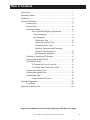
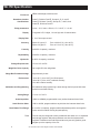
WI-150 Ultra Low-Power
Weight Indicator
User’s Manual
EUROPEAN COUNTRIES
WARNING
This is a Class A product. In a domestic environment this product may cause radio
interference in which the user may be required to take adequate measures.
CAUTION
Risk of electrical shock. Do not remove cover. No user serviceable parts inside. Refer servicing to qualified service personnel.
Weigh-Tronix reserves the right to change
specifications at any time.
12/13/04 150_U.P65 PN 29533-0013K e1 Printed in USA
2
WI-150 Ultra Low-Power Weight Indicator User's Manual
Table of Contents
Introduction .................................................................................... 7
Operations Mode ........................................................................... 7
Keyboard ....................................................................................... 8
Indicator Operation ........................................................................ 9
Powering Up ....................................................................... 9
Annunciators ..................................................................... 10
Operations Mode .............................................................. 10
Gross/Tare/Net Weighing Operations .................... 11
Gross Weighing .................................................. 11
Net Weighing ...................................................... 12
Pushbutton Tare ............................................. 12
Clearing the Active Tare.................................. 12
Creating a Quick Tare ..................................... 12
Entering, Retrieving and Changing
Values in Tare Registers ................................. 13
Net Weighing Operation .................................. 13
Entering or Viewing an ID Number.................................... 14
Viewing and Setting Cutoffs .............................................. 14
Controlling Cutoffs ............................................................ 16
To Access the Control Function ............................. 16
To Activate and Control the Cutoffs ....................... 16
Viewing and Setting Time ................................................. 17
Viewing and Setting Date .................................................. 18
Transmitting Data.............................................................. 18
Communication Protocol ........................................ 19
Indicator Diagnostics ................................................................... 20
Test Mode ........................................................................ 20
Appendix A: Battery Life .............................................................. 22
Pages are numbered consecutively beginning with the cover page.
WI-150 Ultra Low-Power Weight Indicator User's Manual
3
WI-150 Specification
Enclosure
Hazardous location
classifications
Entity parameters
Display
Display Rate
Class I, Divisions I and II, Groups A, B, C, and D;
Class II, Divisions I and II, Groups E, F, and G; and
Class III, Divisions I and II
Vmax = 19 V, Imax = 450 mA, Ci = 0.24 uF, Li = 0 mH
7-segment LCD, 8 digits, 1.0 inch high with 10 annunciators
1, 2 or 5 times per second
Accuracy
Span: ±5.0 ppm/°C
Span: ±10 ppm/°C
Linearity
±0.005% of capacity, maximum
Repeatability
±0.005% of capacity, maximum
Hysteresis
Voltage Requirements
Weigh Bar Drive Capacity
Weigh Bar Excitation Voltage
Environment
Calibration and Programming
Analog Range
Scale Capacities
Scale Division Sizes
Push Button Zero Range
Tare
4
NEMA 4 watertight, stainless steel
Zero: ±.066 uV/°C (-10 to 40°C)
Zero: ±0.13 uV/°C (-30 to 60°C)
0.005% of capacity, maximum
+5.6 to 13.5 volt DC
Up to eight 350 ohm weigh bars
Approximately 4 volts
-10 to 40°C (14 to 104°F) for HB-44 specs
-30 to 60°C (-22 to 140°F) reduced accuracy
10 to 90% relative humidity
All calibration and programming is done through the front panel with data
stored in nonvolatile memory.
-0.14 to +3.5 mV/V
.00001 to 999999, programmable to any number between these limits
.0001 to 20000, programmable to any division size between these limits
0 to ±100% of capacity; programmable independent positive and negative
limits; unit will not allow zeroing beyond capacity.
The unit may be configured to have pushbutton tare and/or 0 to 10 keyboard
tare storage registers. May also pushbutton tare into the keyboard tare
registers. Pushbutton tare and keyboard tare may tare only positive gross
weights up to the capacity of the unit.
WI-150 Ultra Low-Power Weight Indicator User's Manual
Over Range Capacity
Motion Detection Window
Automatic Zero Tracking
The scale will display weights up to and including full scale capacity less any
weight zeroed out by the operator.
Programmable from 0 to 999999 divisions, decimal entries are accepted,
999999 turns motion detection off, default is 1 division.
Window:
Programmable from 0 to 999999 divisions, decimal entries area
accepted, default is 1 division, 0 turns AZT off
Net Mode
Tracking: Configurable to track in net at gross zero
Linearity Adjustment
Analog Low Pass Filter
Software Low Pass Filter
Fiber Optics Cable Length
Options
Rate:
0,1 division per second
Starting
Delay:
2 seconds
Second order correction provides smooth curve fit through three points.
Two section with .06 second time constant.
One section with .05 second time constant; weight averaging over 1 to 10
display intervals.
250 feet maximum
Fiber Optics Interface Card with Real Time Clock
WI-150 Ultra Low-Power Weight Indicator User's Manual
5
6
WI-150 Ultra Low-Power Weight Indicator User's Manual
Introduction
The WI-150 is a full-function, ultra low-power weight indicator which is
designed for Class I, Division I and II, Groups A, B, C, and D; Class II,
Division I and II, Groups E, F, and G; and Class III, Division I and II hazardous locations. The enclosure is also rated NEMA 4. The indicator comes in
two versions. One is powered by an external, rechargeable battery pack and
the other is powered by an AC to DC conversion unit which operates in a
safe area.
This User's Manual is divided into the following sections:
• Introduction
• Operations Mode
• Keyboard
• Indicator Operation
• Indicator Diagnostics
Operations Mode
Operations Mode contains all normal weighing operations. In this mode you
can view or set any of the following parameters if your unit contains the
appropriate options and is so configured:
• pushbutton tare
• one to ten tare registers (numbered 0-9)
• identification number
• one to eight cutoff registers (numbered 0-7)
• cutoff control
• time
• date
Any combination of these items can be secured behind a security code. Any
items secured by the code number can be viewed but not changed unless
you enter the security code.
WI-150 Ultra Low-Power Weight Indicator User's Manual
7
Keyboard
The keyboard consists of 18 keys. Five keys, or buttons, provide all the
basic weighing functions:
• Zero
• Tare
• Gross / Net
• Print
• Units
The other keys are used to access the menus for purposes of accessing
information, testing the indicator, and configuration. The keyboard and key
functions are shown in Figure 1.
Figure 1
Keyboard layout
Puts the battery powered model indicator into an ultra low-power consumption mode called the sleep mode.
Wakes the battery powered model from sleep mode. Is not functional in the
AC/DC powered version.
Zeros the scale in gross/net weigh mode. This button also clears keyed-in
digits on the display before they are accepted.
Changes the unit of measure during operations mode and inserts a decimal
point (.) when keying in values.
8
WI-150 Ultra Low-Power Weight Indicator User's Manual
Enters numbers and specifies tare registers and cutoff values.
Used to access menus and move among choices in a menu.
Sends a print command and is used to select menu items.
Enters a pushbutton tare in gross/net operation. During data entry this key is
used to toggle between positive and negative values. Used to enter a dash
(-) in ID numbers.
Accesses the gross/net weighing mode from any other function and toggles
the unit between gross and net weights, assuming there is an active tare
weight.
Indicator Operation
Powering Up
Upon installation and connection to a power source (either the battery pack
or the AC/DC power source), your indicator is in active mode and is ready to
begin weighing.
The battery powered model has a battery saving "sleep" mode which is
activated after a programmable amount of time. The display reads ASLEEP
when in this mode. To awaken the indicator, press the ON button. The
indicator will return to the same mode of operation it was in when it went to
sleep.
The AC/DC powered model is always in active weighing mode. To turn the
unit off, the power source must be disconnected.
The indicator display, Figure 2, tells you the status of the indicator through
the illumination of annunciators. The annunciators are small black arrows
pointing to the different labels around the display face.
WI-150 Ultra Low-Power Weight Indicator User's Manual
9
Annunciators
Operations Mode
10
Gross -
Illuminates when indicator is in gross weighing mode.
Tare -
Illuminates when you are viewing tare values in the
various registers.
Net -
Illuminates when a tare is in effect and the indicator is in
net weighing mode.
lb, kg, gal -
Illuminates the active unit of measure in weighing mode.
Low Bat -
Illuminates when the battery voltage is low. Battery pack
should be removed from the indicator within 24 hours
and recharged in a safe area.
Motion -
Illuminates when indicator detects scale motion.
Print -
Illuminates when the print key is pressed and while data
are transmitted.
Zero -
Illuminates when the scale is within ±1/4 division of
zero.
Your unit may contain several options and therefore be configured to display
some or all of the following functions: cutoff control, pushbutton tare, one to
ten keyboard tare registers, ID number, cutoffs, time, and date. These can
be viewed and changed if allowed by the security code. This manual
assumes the unit is optioned and configured to allow full access to all
functions. You can disable unneeded options. Instructions are in the
Service Manual. Below is a flowchart and general instructions for moving
around the operations mode menu.
WI-150 Ultra Low-Power Weight Indicator User's Manual
Figure 3
Operations Menu
Press MENU to go
Press and hold MENU to go
Press SELECT to go
or
Press SELECT to select new choice
Press GROSS/NET at any time to return to gross/net weighing mode
Gross/Tare/Net
Weighing Operations
Gross Weighing
To perform gross/net weighing operations, follow these steps:
1. Power up the indicator.
2. If the unit is not in gross mode,
press the GROSS/NET button
once to get to gross/net mode
and again if the net annunciator
is illuminated.
3. Zero the scale by pressing the
ZERO button.
4. Select unit of measure by
pressing the UNITS button.
5. Place weight on the scale.
Battery powered indicator powers up
in the same mode of operation as
when it went to sleep. AC/DC
powered indicator is constantly
powered.
The annunciator illuminates next to
gross. See Figure 2.
No weight is displayed and the zero
annunciator illuminates. See Figure
2.
The units annunciator will point to
the chosen unit of measure.
Gross weight is displayed.
WI-150 Ultra Low-Power Weight Indicator User's Manual
11
Net Weighing
Pushbutton Tare
For net weighing operations a tare needs to be entered. A tare can be
entered by two methods: pushbutton tare or selecting a tare from the tare
register (a memory bank of up to ten tares).
1. With the indicator powered up
and in gross mode, zero the
scale by pressing the ZERO
button.
2. Place the weight to be tared on
the scale.
3. Press the TARE button on the
indicator.
4. Add more weight to the scale.
No weight is displayed and the zero
annunciator illuminates.
The weight of the object is displayed.
The weight is tared, the display
reads zero and the net annunciator
illuminates.
Net weight is displayed.
5. View the gross weight by
pressing the GROSS/NET button. Gross weight is displayed.
6. Press GROSS/NET again to see
net weight.
Clearing the Active Tare
There are two ways to remove the current or active tare weight:
A. Remove all weight from the scale
and press TARE.
B. 1. With the gross or net
annunciator illuminated,
press MENU until TARE is
displayed, then press
CLEAR.
2. Press GROSS/NET key.
Creating a Quick Tare
12
Net weight is displayed.
Pushbutton tare register is cleared,
scale returns to gross mode and no
weight is displayed.
NO TARE is displayed.
Gross weight is displayed. All tare
registers remain intact but are
inactive.
Key in the tare value you want to use and press the TARE key. That value
becomes the active tare.
WI-150 Ultra Low-Power Weight Indicator User's Manual
Entering, Retrieving, and Changing Values in Tare Registers
1. With the gross or net annunciator
illuminated, press the MENU
button until. . .
TARE is displayed.
2. Key in a tare register number to
view the value in the register.
Numbers allowed are 0-9. For
this example, tare register 5 will
be used. Key in numeral 5.
To set a tare register to 0, key
in 0 in step 3A.
If register 5 has an existing
value and you wish to select
that register value as your tare,
you can press PRINT/SELECT
to select that value, then press
GROSS/NET to return to
weighing mode.
There is a one-step way to
accept a keyed in value and
return to gross/net weighing
mode. After the value is keyed
in, press GROSS/NET. Value
is accepted and gross or net
annunciator illuminates.
If you want to review all the
existing tare values, with TARE
displayed, press PRINT/
SELECT then
repeatedly press MENU to
scroll through all tare registers
and the current pushbutton tare
value.
Net Weighing Operation
The tare annunciator illuminates and
the display shows 5
0 , showing that register 5 has no value
entered. Your indicator may have a
value in register 5.
3. You can enter a tare value in a
register in two ways:
A: key in a tare value, or
B: use the pushbutton tare.
A: Key in 155 for this example,
then press PRINT/SELECT.
B: With the desired register
number displayed and the
tare weight on the scale,
press TARE.
The value is accepted and TARE is
displayed.
The register number and new tare
weight are displayed, then the value
is accepted and TARE is displayed
4. Press MENU to proceed to next
tare register.
5. Press GROSS/NET to return to
the weighing mode.
The net annunciator illuminates.
1. After a tare is established, place
the indicator in net mode by
pressing the GROSS/NET button. Net annunciator illuminates. Zero
weight will be displayed with the
container on the scale.
2. Place material to be weighed in
the container on the scale.
Net weight of material is displayed.
WI-150 Ultra Low-Power Weight Indicator User's Manual
13
Entering or Viewing
an ID Number
An 8-digit identification number can be entered on the WI-150. The following
steps tell you how to enter and view an ID number:
1. While in gross weighing mode,
press MENU repeatedly until . . .
ID. is displayed.
2. Press PRINT/SELECT.
The current ID number is displayed.
3. To accept this value press
PRINT/SELECT or
GROSS/NET. To enter a new
value, key in up to 8 digits, then
press PRINT/SELECT to accept
the new value.
Viewing and
Setting Cutoffs
ID. is displayed after ID number is
accepted.
In the weighing industry, a cutoff is a weight at which something happens. In
the case of the WI-150 indicator, an internal electrical connection is broken
causing an external relay to de-energize. This, in turn, causes a motor or
other electrical device to shut off.
Cutoffs are used to load controlled amounts of ingredients. When connected
to the appropriate Fiber-Link, the WI-150 can control up to eight ingredients.
You set the weight of each ingredient and the indicator, through connections
to external relays, will stop the flow of each ingredient when the proper
weight of that ingredient has been added to the scale.
There are two types of cutoffs in the WI-150: the ingredient cutoff (default)
and the setpoint cutoff. With ingredient cutoffs, you tell the indicator the
weight of each ingredient you want and the indicator will call for that much of
each ingredient, no matter what the weight display says. If you want 100
pounds of ingredient #1 and 100 pounds of ingredient #2, you would enter
100 for cutoff #0 and 100 for cutoff #1.
With setpoint cutoffs, you tell the indicator at what weight display you want
the cutoffs to activate. In other words, if you want 100 pounds of ingredient
#1 and 200 pounds of ingredient #2, you would set the first setpoint cutoff at
100 and the second cutoff at 300 pounds because that is what the weight
display will read when you want the actions to occur.
You can tell which kind has been configured in your indicator by looking at
the cutoff number in the Operations Menu in Figure 3. If the cutoff number
has a decimal point following it, the cutoff is a setpoint type. If there is no
decimal, it is configured as an ingredient type.
14
WI-150 Ultra Low-Power Weight Indicator User's Manual
To view or set cutoff values, follow these steps:
1. From gross/net weighing mode,
press MENU repeatedly until . . . . CUTOFFS is displayed.
2. Press PRINT/SELECT.
0. y will be displayed. The number
0 stands for cutoff register #0 and y
is the current value in register 0. The
decimal after the number 0 tells you
that this is a setpoint cutoff. Without
the decimal it means this cutoff is an
ingredient cutoff.
3. You can
A. enter a new value in this
cutoff register
or
B. look at the next cutoff register.
A. Key in the new value. Press
TARE/+/- to toggle the value
between positive and
negative, then press MENU
to accept the value and scroll
to the next cutoff register.
The new value is accepted and
1. y is displayed. The number 1
stands for cutoff register #1 and y is
the current value in register #1.
B. Press MENU to scroll to the
next cutoff register.
1.
y is displayed.
4. Key in a new value as you did in
step #3.
When you are finished viewing
and changing values, press
PRINT/SELECT to return to the
operations mode menu.
CUTOFFS is displayed.
WI-150 Ultra Low-Power Weight Indicator User's Manual
15
Controlling Cutoffs
The WI-150 Indicator allows you to control the cutoff process from the front
panel. Through the WI-150 you may: enable/disable the cutoff process,
continue or interrupt the operation of a cutoff before its setpoint has been
reached, and/or terminate the process at any time before the last cutoff has
been reached.
To Access the Control
Function
1. From Gross/Net Weighing Mode,
press MENU one time. . .
Control is displayed.
2. With Control displayed, press
SELECT. . .
HALtEd is displayed.
Cutoff values (positive or
negative) must be entered
before you can control them.
To Activate and Control
the Cutoffs
There are two ways--Methods A or B--to activate the cutoffs. Method A
activates the cutoffs immediately while displaying the changing weight on
the scale, and Method B allows you to view the weight on the scale before
the cutoffs are activated.
Method A:
1. With HALtEd displayed, press
MENU. . .
2. Press SELECT. . .
Method B:
1. With HALtEd displayed, press
SELECT...
2. Press MENU....
16
run is displayed.
r xxxxxx is displayed. xxxxxx
represents the weight as it changes
on the scale.
h xxxxxx is displayed. xxxxxx
represents the weight on the scale.
r xxxxxx is displayed. xxxxxx
represents the weight as it changes
on the scale.
WI-150 Ultra Low-Power Weight Indicator User's Manual
To halt active cutoffs
You may halt an active cutoff at any time.
With r xxxxxx displayed, press any
key. . .
To return to Gross/Net
Weighing Mode
Viewing and Setting
Time (Option)
You may return to G/N Weighing
Mode at any time during this
process by pressing GROSS/NET...
Display returns to G/N Weighing
Mode.
Your indicator must have the optional Fiber Optics Interface Card and be
configured to allow the following . . .
1. From gross/net weighing mode,
press MENU repeatedly until . . . . HOUR is displayed.
2. Press PRINT/SELECT.
If you enter an incorrect digit,
press the ZERO/CLEAR key to
clear the display one digit at a
time.
h xxxxxx is displayed and cutoffs
are halted.
In the 12 hour clock configuration
you will see time displayed as hours,
minutes and A for A.M. or P for P.M.
(09 40 A). In the 24 hour clock you
will see hours, minutes and seconds
(09 40 38).
3. To set the 12 hour clock, key in
new hours, minutes, and press
TARE/+/- key to toggle A.M.
and P.M.
To set the 24 hour clock, key in
new hours, minutes, and seconds.
After the clock is set, press
PRINT/SELECT to start the
clock and return to operations
mode menu,
HOUR is displayed and the clock
begins at the new time setting.
or
press GROSS/NET to return
to gross/net weighing mode.
Display returns to gross/net mode
and the clock begins at the new time
setting.
WI-150 Ultra Low-Power Weight Indicator User's Manual
17
Viewing and Setting
the Date (Option)
Your indicator must have the optional Fiber Optics Interface Card and be
configured to allow the following . . .
1. From gross/net weighing mode,
press MENU repeatedly until . . .
DAY is displayed.
Depending on the configuration of
your indicator you will see the date
displayed in one of three ways:
• month-day-year, or
• day-month-year,
• year-month-day.
2. Press PRINT/SELECT.
If you enter an incorrect digit,
press the ZERO/CLEAR key to
clear the display one digit at a
time.
3. To change the date, key in the
new data.
4. Press PRINT/SELECT to return
to the operations mode menu
The date is accepted and DAY is
displayed.
or
press GROSS/NET to return to
gross/net weighing mode.
Transmitting Data
Your indicator is capable of sending and receiving serial data via an optional
Fiber Optics Interface Card to an optional Fiber-Link fiber optics converter.
If your indicator contains this option
and is configured to allow printing,
from the gross/net weighing mode
press the PRINT/SELECT key.
18
The date is accepted and the display
returns to gross/net mode.
The PRINT annunciator (See Figure
2) will illuminate while data is
transmitted and the data configured
to be printed will be output to the
printer. See Figure 4 for a sample
printout.
WI-150 Ultra Low-Power Weight Indicator User's Manual
Figure 4
Sample WI-150 Printout
Communication Protocol
A new WI-150 indicator attached to an empty scale and a compatible printer
will print the following:
An enquire code can be sent to the AC/DC powered version of the WI-150.
This will prompt the indicator to send a standard printout. The default
enquire code number is an ASCII decimal 005. This number can be
changed in configuration.
The default settings for serial output are:
Baud
Parity
Stops
1200
Clear
1
WI-150 Ultra Low-Power Weight Indicator User's Manual
19
Indicator Diagnostics
Test Mode
The test mode is used to test various functions of the WI-150. The test
menu is shown in Figure 5. Instructions for using the test menu are found
below.
Figure 5
Test Menu
1. Enter the test mode from gross/net operation by pressing and holding
the MENU key until TEST is displayed. SEALED or UNSEALED is
displayed briefly while you hold the key.
2. Move to the right through the menu selections by pressing MENU
briefly. Move to the left through the menu selections by pressing MENU
for 1 second or hold down for continuous scrolling.
20
WI-150 Ultra Low-Power Weight Indicator User's Manual
3. To move down a level in the hierarchy, press PRINT/SELECT. Anytime
you wish to get to the next higher level in the hierarchy, press and hold
PRINT/SELECT for approximately 1.5 seconds or press PRINT/SELECT whenever END is displayed.
4. Press MENU to toggle between choices.
5. Press GROSS/NET to return to gross/net operation at any time.
Below are the specific directions and explanations for the items you see in
the test menu:
VERSION —
Under version are the Weigh-Tronix part number and
revision number for the software found in your indicator.
Weigh-Tronix part numbers are divided into two parts:
the prefix and the dash number with revision letter(s).
DISPLAY —
With DISPLAY displayed, press PRINT/SELECT and
the top row of annunciators turns on. Press PRINT/
SELECT again and a dynamic test is run. Press MENU
to stop the dynamic test or consecutively press MENU
to step through the display test routine. Press PRINT/
SELECT when the dynamic test is active to return the
unit to DISPLAY.
BUTTONS —
With BUTTONS displayed, press PRINT/SELECT and
an underscore will appear on the screen. Press any key,
except MENU, ON, or OFF keys, to check for proper
key functioning. After testing the buttons, press MENU
to return to the BUTTONS display.
BATTERY —
Battery voltage is displayed in tenths of a volt. In the
battery pack version, the LOW BAT annunciator comes
on when the voltage reaches approximately 7.3 volts.
A to D —
Displays the analog to digital counts. The span is
normally 20000 counts per millivolt per volt. With a
calibrator at zero millivolts per volt, the displayed value
should be between -200 and +200.
SERIAL —
Allows you to test the serial port. READY will be displayed. Pressing the MENU key puts LOOP or NO
LOOP on the display. With pins 2 and 3 connected on
the interface box, LOOP is displayed. With them
disconnected, NO LOOP is displayed. The fiber optics
cables from the indicator may be butted together and
LOOP will be displayed.
WI-150 Ultra Low-Power Weight Indicator User's Manual
21
Appendix A: Battery Life
Percent of Time On
Number of Weight Sensors
1
2
3
4
6
8
0
2600
2600
2600
2600
2600
2600
5
2019
1962
1912
1871
1787
1730
10
1651
1576
1512
1461
1361
1297
20
1209
1130
1066
1016
922
864
30
954
881
823
778
697
648
40
788
722
670
631
560
518
50
671
612
565
531
468
432
60
584
531
489
458
402
370
70
517
468
430
402
353
324
80
464
419
385
359
314
287
90
421
380
348
324
283
259
100
385
347
317
295
257
235
Battery Life in Hours for WI-150 without SC-150
Percent of Time On
Number of Weight Sensors
1
2
3
4
6
8
0
2600
2600
2600
2600
2600
2600
5
1440
1411
1385
1363
1318
1287
10
996
968
944
924
883
855
20
616
595
576
562
532
512
30
446
429
415
403
384
365
40
349
336
324
315
296
284
50
287
276
266
258
242
232
60
244
234
225
219
205
196
70
219
203
196
190
178
170
80
187
180
173
168
157
150
90
168
161
155
150
141
134
100
152
146
140
136
127
121
Battery Life in Hours for WI-150 with SC-150
22
WI-150 Ultra Low-Power Weight Indicator User's Manual
Declaration of Conformance to SMA Standard
Year of Declaration 2002
Production Meets Type
®*
We the manufacturer of
Model
Type
Certificate and Number
Issued by
WI-150
Electronic Indicator
NTEP CC 92-206
NCWM
Declare in our responsibility the conformance of the above listed models and types to the
mentioned certificates and the requirements of the SMA standard.
This declaration becomes valid when the SMA Conformance Logo, having our name or trademark is applied to the device or its accompanying documentation.
* SMA PRODUCTION MEETS TYPE DEVICE MANUFACTURER Conformance Logo and Design are a registered
trademark of the Scale Manufacturers Association
WI-150 Ultra Low-Power Weight Indicator User's Manual
23
Avery Weigh-Tronix USA
1000 Armstrong Dr.
Fairmont, MN 56031 USA
Telephone: 507-238-4461
Facsimile: 507-238-4195
e-mail: [email protected]
www.wtxweb.com
Avery Weigh-Tronix UK
Foundry Lane
Smethwick, West Midlands
England B66 2LP
Tel: +44 870 90 34343
Fax: +44 121 224 8183
Email: [email protected]
Web site:www.averyweigh-tronix.com
Avery Weigh-Tronix Canada, ULC
217 Brunswick Boulevard
Pointe Claire, QC H9R 4R7 Canada
Telephone: 514-695-0380
Toll free: 800-561-9461
Facsimile: 514-695-6820
www.weigh-tronix.ca
Weigh Bar® is a registered trademark of Weigh-Tronix Inc.