1
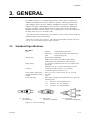
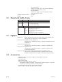
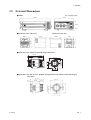
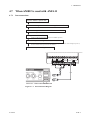
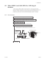
User's
Manual
Models AM012
Magnetic Flowmeter Calibrator
MANUAL AMENDMENT
IM 1E6K2-10E
User’s manual IM1E6K2-E (6th Edition) is amended for the calibration of AXFA11, AXFA14 and
AXF integral flowmeter.
Page
Contents
Page 2-1-1
2-1 Model Name and Specifications
Data plate description is changed
Page 3-1
3 GENERAL
ADMAG AXF Magnetic Flowmeter is added
Page 3-2-1, 3-2-2
3-1 Standard Specifications
3-2 Model and Suffix Codes
3-3 Options
3-4 Accessories
Page 3-3-1
3-5 External Dimensions
Page 4-1-1
4 Operation
Page 4-19-1, 4-19-2, 4-19-3, 4-19-4
4-7 When AM012 is used with AXFA11
Page 4-19-5, 4-19-6, 4-19-7, 4-19-8, 4-19-9
4-8 When AM012 is used with AXFA14
or AXF integral Flowmeter
Page 3-2-1, 3-2-2
3.1 Standard Specifications
Page
3.2
3.3
3.4
3-2-2
Model and Suffix Codes
Options
Accessories
Page 3-3-1
3.5 External Dimensions
Page 4-19-10 to 4-14-16
4.9 When AM012 is used with FOUNDATION
Fieldbus Communication type AXFA14
or AXF integral flowmeter
Junction box for ADMAG AXF (optional code / AXF) is added
Junction box for AXFA14 and AXF integral flowmeter is added
Calibration Procedures for AXFA11, AXFA14 and AXF
integral flowmeter are added
AXFA11 calibration is added
AXFA14 and AXF integral flowmeter calibration is added
Junction box for FOUNDATION Fieldbus Communication type is added
Junction box for FOUNDATION Fieldbus Communication type
(optional code /FB) is added
Junction box for FOUNDATION Fieldbus Communication type is added
Calibration procedures for FOUNDATION Fieldbus Communication type
AXFA14 or AXF integral flowmeter are added
13th Nov. 2006
Yokogawa Electric Corporation
IM 1E6K2-10E
2nd Edition
2. HANDLING PRECAUTIONS AND REQUISITES
2. HANDLING PRECAUTIONS
AND REQUISITES
The Model AM012 Magnetic Flowmeter Calibrator is thoroughly tested at the factory
before shipment. However, when the instrument is delivered, make a visual check to
ascertain that no damage occurred during shipment.
This section describes important precautions and requisites to be observed when
handling the instrument. Carefully read this manual before using the instrument.
If there are any problems or questions, please contact the nearest YOKOGAWA
service center or the dealer from whom the instrument was purchased.
2.1
Model Name and Specifications
The Model name and main data are indicated on the name plate attached at the rear of
the case (see Figure 2.1).
CALIBRATOR
MODEL
*A
SUPPLY
AM01290-132VAC
47-63Hz
180 — 264V AC at 200V series
NO.
Made in
Figure 2.1 Data Plate
Verify that the data are the same as those specified at the time when it was ordered,
referring to the Model and Suffix Codes in Section 3.2.
When contacting us, please indicate the Model and the instrument serial number.
2.2
Handling and Storing Precautions and Requisites
Precautions and requisites to be taken when handling and storing this instrument:
(1) Prevent excessive shock to the instrument.
(2) Protect the instrument from water and precipitation.
(3) Calibrate the instrument at normal temperature and humidity.
(4) Avoid installation or storage of the instrument in a corrosive atmosphere.
(5) Store the instrument in a location:
• free from water and precipitation.
• relatively free from vibration and shock.
• where the ambient temperature is between 0°C and 40°C and the humidity is
between 5% and 80% relative humidity (well-ventilated and without condensation).
IM 1E6K2-E
2-1-1
3. GENERAL
3. GENERAL
The AM012 Calibrator is a standard signal generator used to check or calibrate the
ADMAG AXF Magnetic Flowmeter (AXFA11, AXFA14, AXF Integral Flowmeter),
AM11 Magnetic Flow Converter, ADMAG AE Magnetic Flowmeter, ADMAG CA
Magnetic Flowmeter, AM12 Magnetic Flow Converter, AM100A/B or AM200A/B
Magnetic Flowmeter, YMA11 Magnetic Flow Converter and Compact YEWMAG
Magnetic Flowmeter (CYM for short), styles A and B.(Style A or style B is indicated on
the name plate: style A as *A and B as *B.)
The excitation load is incorporated in the calibrator, so the converter can be checked or
calibrated without using a flow detector.
Span can be set from 0 to 10.99 m/s. The output signal related to the span can be set
to 0, 25, 50, 75 and 100% using the output (%) knob.
3.1
Standard Specifications
● AM012
Case
: Material
: Unsaturated polyester resin
Dimensions : 110mm (H)×235mm (W)×364mm (D)
Color
: Light grayish green
Wiring cable
: Special cables supplied are:
AM012 power cord, signal and excitation cables
CYM signal cable and excitation cable (optional)
Range setting
: 0 to 10.99 m/s (minimum scale 0.01 m/s) with the spansetting dial.
CHECK, 0, 25, 50, 75, 100% with output (%) knob.
Accuracy
: ±0.04% of set value (span 0.1 m/s or greater)
+0.04 mm/s (span less than 0.1 m/s)
Power supply requirements : 90 to 132 V AC or 180 to 264 V AC, 47 to 63 Hz
Ambient temperature limits : 0 to 40°C
Weight
: 4.2kg
Power cord plug
: Three types of plugs are available (select any one of the
following three):
(–1)
For 100 V AC (for domestic use)
(–2)
For 100 V AC (UL Standard)
(–3)
For 200 V AC (CEE Standard)
(–1) 100 V series
(for domestic use)
Figure 3.1
IM 1E6K2-E
(–2) 100 V series
(conforms to UL standard)
(–3) 200 V series
(conforms to CEE standard)
Power Cord Plugs
3-1
3. GENERAL
● Junction box for ADMAG AE and ADMAG CA
Case
: Material
: Stainless steel
Dimensions : 140.5mm(H)×112.4mm(W)×112.4mm(D)
Color
: Light gray
Power supply requirements : Power supply code -A1;
Range 80 to 264V AC, 47 to 63Hz/100 to 130V DC,
Power supply code -D1;
Range 20.4 to 28.8 V DC (except /FB of ADMAG AE)
Ambient temperature limits : 0 to 40°C
Weight
: 1kg
● Junction box for ADMAG SE
Case
: Material
: Stainless steel
Dimensions : 140.5mm(H)×112.4mm(W)×112.4mm(D)
Color
: Light gray
Power supply requirements : Power supply code -A1;
Range 80 to 127 V AC, 47 to 63 Hz/90 to 110 V DC
Power supply code -A2;
Range 180 to 264 V AC
Power supply code -D1;
Range 20.4 to 28.8 V DC/AC
Ambient temperature limits : 0 to 40°C
Weight
: 1kg
● Junction box for AXFA14 and AXF integral flowmeter
Case
: Material
: Aluminum diecast
Dimensions : 240mm(H)×180mm(W)×145.5mm(D)
Color
: Silver gray
Power supply requirements : Power supply code 1;
• AC specifications
Rated power supply: 100 to 240 V AC, 50/60 Hz
(Operating voltage range: 80 to 264 V AC)
• DC specifications
Rated power supply: 100 to 120 V DC (Operating
voltage range: 90 to 130 V DC)
Power supply code 2;
• AC specifications
Rated power supply: 24 V AC, 50/60 Hz (Operating
voltage range: 20.4 to 28.8 V AC)
• DC specifications
Rated power supply: 24 V DC (Operating voltage
range: 20.4 to 28.8 V DC)
Ambient temperature limits : 0 to 40°C
Weight
: 2.7kg
● Junction box for FOUNDATION Fieldbus Communication type AXFA14 and AXF
integral flowmeter
Case
: Material
: Aluminum diecast
Dimensions : 197mm(H)×180mm(W)×145.5mm(D)
Color
: Silver gray
Power supply requirements : Power supply code 1;
• AC specifications
Rated power supply: 100 to 240 V AC, 50/60 Hz
(Operating voltage range: 80 to 264 V AC)
• DC specifications
Rated power supply: 100 to 120 V DC (Operating
voltage range: 90 to 130 V DC)
Power supply code 2;
3-2-1
IM 1E6K2-E
• AC specifications
Rated power supply: 24 V AC, 50/60 Hz (Operating
voltage range: 20.4 to 28.8 V AC)
• DC specifications
Rated power supply: 24 V DC (Operating voltage
range: 20.4 to 28.8 V DC)
Ambient temperature limits : 0 to 40°C
Weight
3.2
: 2.7kg
Model and Suffix Codes
Model
Suffix Code
AM012
........................
-1.....................
Power code -2.....................
-3.....................
Style code
*A..............
100 V version (Type JIS plug)
100 V version (Type UL plug)
200 V version (Type CEE plug)
Options
With cable for CYM
With junction box for AE and CA
With junction box for SE
With junction box for AXFA14 and AXF
integral Flowmeter
With junction box for FOUNDATION Fieldbus
Communication type AXFA14 and AXF integral Flowmeter
/CYM
/AE
/SE
/AXF
/FB
3.3
Description
Magnetic flowmeter calibrator
Style A
Options
CYM cables
: Signal and excitation cables for CYMs (option code CYM) are available optionally to calibrate the Compact YEWMAG.
Junction box for ADMAG AE and ADMAG CA:
Junction box are available optionally to calibrate the ADMAG AE and
ADMAG CA.
Junction box for ADMAG SE:
Junction box are available optionally to calibrate the ADMAG SE.
Junction box for ADMAG AXF:
Junction box are available optionally to calibrate the AXFA14 and
AXF integral flowmeter.
Junction box for FOUNDATION Fieldbus Communication type ADMAG AXF:
Junction box are available optionally to calibrate the FOUNDATION
Fieldbus Communication type AXFA14 and AXF integral flowmeter.
3.4
Accessories
•
•
•
•
•
One power supply cord (types of plugs vary depending on MS code.)
One fuse (0.2 A)
One signal cable
One excitation cable
Cable for CYM (When /CYM is selected)
The cables and a fuse are stored in a cord container on the rear panel. To open the
container cover, pull the container cover knob forward.
• Junction box (When /AE, /SE, /AXF or /FB is selected)
• Special cable for ADMAG SE (When /SE is selected)
3-2-2
IM 1E6K2-E
3. GENERAL
3.5
External Dimensions
●AM012
unit : mm(approx,inch)
364(14.3)
235(9.3)
100(3.9)
10(0.4)
●Junction box (for AE & CA)
Junction box (for SE)
140.5(5.5)
140.5(5.5)
112.4(4.4)
112.4(4.4)
112.4(4.4)
112.4(4.4)
●Junction box (for AXFA14 and AXF integral flowmeter)
71(2.8)
240(9.45)
103(4.06)
66(2.6)
145.5(5.73)
57(2.24) 49(1.92)
ø128(5.04)
180(7.09)
ø87(3.43)
●Junction box (for FOUNDATION Fieldbus Communication type AXFA14 and AXF integral
flowmeter)
197(7.76)
103(4.06)
180(7.09)
66(2.6)
145.5(5.73)
57(2.24) 49(1.92)
28(1.1)
ø87(3.43)
IM 1E6K2-E
3-3-1
3. GENERAL
3.6
Component Identification
(Rear Panel)
Function Switch
Excitation Connector
Output (%) Knob
Ground Terminal
Cord Container Cover
Output Signal Connector
Span-Setting Dial
Power Supply
Connector
Exciting Current
Polarity Indicator
Figure 3.6 Component Identification
3-3-2
IM 1E6K2-E
4. OPERATION
4. OPERATION
This chapter describes calibration procedures when the AM012 calibrator is used with:
AM11(in Section 4.1), ADMAG AE, ADMAG CA(in Section 4.2), ADMAG SE(in
Section 4.3), AM12, AM100A/B, AM200A/B(in Section 4.4), YMA11(in Section 4.5),
Compact YEWMAG (CYM)(in Section 4.6), AXFA11(in Section 4.7), AXFA14 and
AXF integral flowmeter(in Section 4.8).
Refer to each section to perform the desired calibration.
IMPORTANT
• As a rule, calibration of the converter should be implemented in a maintenance service
shop where the necessary tools are provided.
• The amplifier unit contains sensitive parts that may be damaged by static electricity.
Excercise care so as not to directly touch the electronic parts or circuit patterns on the
board, for example, by preventing static electrification by using grounded wrist straps
when handing the unit. Also take precautions such as placing a removed amplifier unit
into a bag with an antistatic coating.
4.1
When AM012 is used with AM11
4.1.1
Interconnections
Turn the AM11 power OFF.
Disconnect the signal and excitation wirings for the AM11.
Connect the signal and excitation cables to the AM012.
Connect the power and ground cords to the AM012.
(Ground the AM012 to prevent it from being affected by external noises. After turning the power on,
let the instrument warm up for at least ten minutes.)
Proceed to 4.1.2 Checking Procedure.
(Shield)
(Shield)
(White)
(White)
(Black)
(Black)
Figure 4.1.1 Interconnection Diagram
IM 1E6K2-E
4-1-1
4. OPERATION
4.7
When AM012 is used with AXFA11
4.7.1
Interconnections
Turn the AXFA11 power OFF.
Disconnect the signal and excitation wirings for the AXFA11.
Connect the signal and excitation cables to the AM012.
(refer to Figure 4.7.1)
Change AM012 FUNCTION
(Slide the AM012 FUNCTION switch to the ADMAG position)
Connect the power and ground cords to the AM012.
(Ground the AM012 to prevent it from being affected by external noises. After turning the power on,
let the instrument warm up for at least ten minutes.)
Proceed to 4.7.2 Checking Procedure.
I+
I–
CUR OUT
SO1+ SO2+ COM
STATUS OUT
AL+
AL–
C
N/–
L/+
EX1
POWER SUPPLY
(White)
EX2
EXCITER
P+
A
B
SB
SIGNAL
(White)
(Shield)
(Shield)
SA
ALARM OUT
P–
PULSE OUT
SI1+
(Black)
SI2+ COM
STATUS IN
(Black)
Figure 4.1.1 Interconnection Diagram
Figure 4.7.1
IM 1E6K2-E
Interconnection Diagram
4-19-1
4. OPERATION
4.7.2
Checking Procedures
(1) Standard dual frequency excitation
Confirm AM012 FUNCTION.
Confirm the AM012 FUNCTION switch to the “ADMAG” position.
Change the AXFA11 set values.
Set following parameters before wiring AXFA11
to AM012.
Set the “C30 Select Flow Tube” to “Calibrator”
Set the “C20 Measure Mode” to “Standard DF”. (Before changing the mode, write down
the previous value)
Set both the “C21 Low MF” and “C22 High MF” meter factors to 1.0000. (Before changing the
meter factors, write down the previous values.)
See Section 4.7.3, “Meter Factor Setting.”
Turn the AXFA11 power ON.
Two excitation lamps will flash alternately. (See Note 1 below)
After turning ON the power, let the instrument warm up for at least three minutes.
Span set on the AM012.
Set the flow velocity of the span with the AM012 span dial. Firstly, be sure to confirm that the "C31
Nominal Size Unit" parameter of AXFA11 is set to "mm". The flow velocity(m/s) can be checked
with "C44 Velocity Check" parameter of AXFA11.
Check the zero point.
Set the output (%) knob to 0% to check the zero point. To check the span accurately, record the
indicated value. (See Note 2 below)
Check the span and output accuracy.
Turn the output (%) knob to 25%, 50%, 75% and 100% in turn to check the indicated values.
(Subtract the zero point value from the indicated value to check the output accuracy.) When the
knob is set to CHECK, common mode noise rejection can be checked (See Note 3 below).
Return the AXFA11 set values to their initial values.
Return the C30 Select Flow Tube to “ADMAG AXF”
Return the "C20 Measure Mode" to the initial value which was previously recorded.
Return both the “C21 Low MF” and “C22 High MF” meter factors to their initial values which
were previously recorded.
Turn the AXFA11 power OFF.
Remove the power supply and ground cords from the AM012.
Remove the signal and excitation cables from the AM012.
Connect the AXFA11 signal and excitation cables
End
Note 1 : If no exciting current flows, the two excitation lamps do not flash correctly.
Note 2 : When the zero readjustment is available (i.e. the flowtube has been filled with fluid and the fluid
velocity is completely zero) after checking of AXFA11, it is convenient to carry out zero adjustment
instead of subtraction the zero point value.
In case that zero readjustment is not available, do not carry out zero adjustment of AXFA11.
Note 3 : A common mode noise signal equivalent to a set value with the span-setting dial is output from the
AM012.
4-19-2
IM 1E6K2-E
4. OPERATION
(2) Enhanced dual frequency excitation
When the AXFA11 is used in combination with the AXF flowtube which supports the
enhanced dual frequency excitation (optional code HF1 or HF2), the calibration of that
excitation is necessary.
Confirm AM012 FUNCTION.
Confirm the AM012 FUNCTION switch to the “ADMAG” position.
Change the AXFA11 set values.
Set following parameters before wiring AXFA11
to AM012.
Set the “C30 Select Flow Tube” to “Calibrator”
Set the “C20 Measure Mode” to “Enhanced DF”. (Before changing the mode, write down
the previous value)
Set both the “C23 Low MF (EDF)” and “C24 High MF (EDF)” meter factors to 1.0000. (Before
changing the meter factors, write down the previous values.)
See Section 4.7.3, “Meter Factor Setting.”
Turn the AXFA11 power ON.
Two excitation lamps will flash alternately. (See Note 1 below)
After turning ON the power, let the instrument warm up for at least three minutes.
Span set on the AM012.
Set the flow velocity of the span with the AM012 span dial. Firstly, be sure to confirm that the "C31
Nominal Size Unit" parameter of AXFA11 is set to "mm". The flow velocity(m/s) can be checked
with "C44 Velocity Check" parameter of AXFA11.
Check the zero point.
Set the output (%) knob to 0% to check the zero point. To check the span accurately, record the
indicated value. (See Note 2 below)
Check the span and output accuracy.
Turn the output (%) knob to 25%, 50%, 75% and 100% in turn to check the indicated values.
(Subtract the zero point value from the indicated value to check the output accuracy.) When the
knob is set to CHECK, common mode noise rejection can be checked (See Note 3 below).
Return the AXFA11 set values to their initial values.
Return the C30 Select Flow Tube to “ADMAG AXF”
Return the "C20 Measure Mode" to the initial value which was previously recorded.
Return both the “C23 Low MF (EDF)” and “C24 High MF (EDF)” meter factors to their initial
values which were previously recorded.
Turn the AXFA11 power OFF.
Remove the power supply and ground cords from the AM012.
Remove the signal and excitation cables from the AM012.
Connect the AXFA11 signal and excitation cables
End
Note 1 : If no exciting current flows, the two excitation lamps do not flash correctly.
Note 2 : When the zero readjustment is available (i.e. the flowtube has been filled with fluid and the fluid
velocity is completely zero) after checking of AXFA11, it is convenient to carry out zero adjustment
instead of subtraction the zero point value.
In case that zero readjustment is not available, do not carry out zero adjustment of AXFA11.
Note 3 : A common mode noise signal equivalent to a set value with the span-setting dial is output from the
AM012.
IM 1E6K2-E
4-19-3
4. OPERATION
4.7.3
Meter Factor Setting
The meter factors can be set using three AXFA11 converter keys or HHT.
The standard dual frequency excitation requires two meter factors such as "C21 Low
MF" and "C22 High MF". In case of calibration, two meter factors set to 1.0000.
The enhanced dual frequency excitation requires two meter factors such as "C23 Low
MF (EDF)" and "C24 High MF (EDF)". In case of calibration, two meter foctors set to
1.0000.
For details, refer to the AXFA11 User’s Manual IM 01E20C01-01E.
4-19-4
IM 1E6K2-E
4. OPERATION
4.8
When AM012 is used with AXFA14 or AXF integral
flowmeter
When using the AM012 calibrator with the AXFA14 or AXF integral flowmeter,
remove the amplifier only from the converter and put it in the dedicated junction box for
calibration. If /AXF is selected for the optional specifications, this junction box is
provided. The junction box can also be obtained separately. (Part No : F9559DJ)
4.8.1
Interconnections
Connection of the AM012 signal and excitation cables
See Figure 4.8.1 for details of the connection.
Connect the signal and excitation cables to the junction box.
See Figure 4.8.1 for details of the connection.
Change AM012 FUNCTIONS
Slide the AM012 FUNCTION switch to the ADMAG position
Connect the power and ground cables to the AM012.
Connect the power cable to the AM012.
Ground the terminal of the AM012 to protect it from external noise.
After turning the power on, let the instrument warm up for at least ten minutes.
POWER
90 to 132 VAC
(Power code: -1 and -2)
or
180 to 264 VAC
(Power code: -3)
50/60 Hz
AM012
Junction Box Terminal
G
EX1
EX2
C
A
B
Figure 4.8.1
(G)
EX1
EX2
C
N/L/+
Power supply
A
B
Interconnection Diagram
To next page
IM 1E6K2-E
4-19-5
4. OPERATION
Remove the amplifier unit from the converter.
• How to remove the amplifier unit (AXFA14 and AXF integral flowmeter are same procedure).
See IM 01E20D01-01E regarding the procedure of removing amplifier unit.
(1) Turn off the power.
(2) Loosen cover locking screw, and remove the cover.
(3) Remove wiring connectors 1 and 2 (refer to Figure 4.8.2) from the amplifier unit.
Remove them carefully, without applying excessive force.
(4) Loosen the three mounting screws while holding the unit with your hand.
(5) Pull the unit straight out.
Wiring connector 1
Amplifier mounting
connectors
Wiring connector 1
Amplifier mounting
screw (three units)
Rod
Wiring connector 2
Wiring connector 2
Figure 4.8.2 Removing / Assembling the Amplifier
Place the amplifier unit in the junction box.
• Only the amplifier is housed in the junction box.
(1) Insert the connector pins of the amplifier into the two connectors on the terminal
board of the junction box, aligning the holes of the plate with the positioning pins as
shown in the figure.
(2) Engage the connectors to the amplifier. (See Figure 4.8.3.)
(3) After checking that the connections are secure, firmly tighten the fixing three screws.
(4) Screw in the cover firmly as shown in Figure 4.8.3 where general-purpose use and
sanitary type is shown. In case of explosion proof type, use the cover of 10mm
thickness into amplifier unit side.
GLASS:10mm
GLASS:3mm
Figure 4.8.3 Setting Converter Unit in Junction Box
Proceed to 4.8.2 Checking Procedure.
4-19-6
IM 1E6K2-E
4. OPERATION
4.8.2
Checking Procedure
(1) Standard dual frequency excitation
Change Function.
Slide the AM012 FUNCTION switch to the ADMAG posiotion.
Turn on tne Junction box power.
Two excitation lamps will flash alternately at regular intervals. (See Note 1 below)
After turning on the power, let the instrument warm up for at least three minutes.
Span setting
Set the flow velocity of the span with the AM012 span dial. Firstly, be sure to confirm that the "C31
Nominal Size Unit" parameter of converter is set to "mm". The flow velocity can be checked with
"C44 Velocity Check" parameter of the converter.
Changing the setting of AXF AMPLIFIER UNIT
Set the “C20 Measure Mode” to “Standard DF”. (Before changing the mode, write down
the previous value)
Set the meter factors of “C21 Low MF” and “C22 High MF” to 1.0000. (Before changing the
settings, record the previous values.)
Check the zero point
Turn the output knob of AM012 to 0% to check the zero point. To check the span accurately, record
the indicated value. (See Note 2 below)
Check the span and output accuracy
Turn the output knob to 25%, 50%, 75% and 100% in turn and check the indicated values. (Subtract
the zero point value from the indicated value to check the output accuracy.) Set the knob to CHECK
to check the common mode noise rejection. (See Note 3 below)
Return the ADMAG AXF AMPLIFIER UNIT set values to their initial values.
Return the "C20 Measure Mode" to the initial value which was previonsly recorded.
Return the two meter factors of “C21 Low MF” and “C22 High MF” to the value recorded before
the change.
Turn off the Junction box power.
Remove the power supply and ground cables from the AM012.
Remove the signal and excitation cables from the AM012.
Remove the amplifier unit from the Junction box .
Loosen the fixing screws, disengage the connectors, then remove the amplifier unit.
Install the amplifier into the converter.
(1) To install the amplifier assembly, follow the procedures used to remove it in the reverse order.
(Refer to Figure 4.8.2)
(2) Replace the unit by pushing it in, taking care not to damage the amplifier mounting connectors on
the circuit board.
(3) Carefully connect wiring connectors 1 and 2 to the amplifier unit, making sure that the
connectors’ directions are correct. Let wiring connector 2 pass along the amplifier side of the rod.
(4) Tighten the three mounting screws while holding the unit with your hand.
(5) Screw in the cover, taking care not to entangle the cables of the wiring connectors.
(6) Tighten cover locking screw.
End
Note 1 : If no exciting current flows, the two excitation lamps do not flash correctly.
Note 2 : When the zero readjustment is available (i.e. the flowtube has been filled with fluid and the fluid velocity is
completely zero) after checking of AXFA14 or AXF integral flowmeter, it is convenient to carry out zero
adjustment instead of subtraction the zero point value.
In case that zero readjustment is not available, do not carry out zero adjustment of AXFA14 or AXF
integral flowmeter.
Note 3 : A common mode noise signal equivalent to a set value with the span-setting dial is output from the AM012.
IM 1E6K2-E
4-19-7
4. OPERATION
(2) Enhanced dual frequency excitation
When the AXFA14 is used in combination with the AXF flowtube which supports the
enhanced dual frequency excitation (optional code HF1 or HF2), the calibration of that
excitation is necessary.
In case of AXF integral flowmeter which supports the enhanced dual frequency
excitation (optional code HF1 or HF2), the calibration of that excitation is necessary.
Change Function.
Slide the AM012 FUNCTION switch to the ADMAG posiotion.
Turn on tne Junction box power.
Two excitation lamps will flash alternately at regular intervals. (See Note 1 below)
After turning on the power, let the instrument warm up for at least three minutes.
Span setting
Set the flow velocity of the span with the AM012 span dial. Firstly, be sure to confirm that the "C31
Nominal Size Unit" parameter of converter is set to "mm". The flow velocity can be checked with
"C44 Velocity Check" parameter of the converter.
Changing the setting of AXF AMPLIFIER UNIT
Set the “C20 Measure Mode” to “Enhanced DF”. (Before changing the mode, write down
the previous value)
Set the meter factors of “C23 Low MF (EDF)” and “C24 High MF (EDF)” to 1.0000. (Before
changing the settings, record the previous values.)
Check the zero point
Turn the output knob of AM012 to 0% to check the zero point. To check the span accurately, record
the indicated value. (See Note 2 below)
Check the span and output accuracy
Turn the output knob to 25%, 50%, 75% and 100% in turn and check the indicated values. (Subtract
the zero point value from the indicated value to check the output accuracy.) Set the knob to CHECK
to check the common mode noise rejection. (See Note 3 below)
Return the ADMAG AXF AMPLIFIER UNIT set values to their initial values.
Return the "C20 Measure Mode" to the initial value which was previonsly recorded.
Return the two meter factors of “C23 Low MF (EDF)” and “C24 High MF (EDF)” to the value
recorded before the change.
Turn off the Junction box power.
Remove the power supply and ground cables from the AM012.
Remove the signal and excitation cables from the AM012.
Remove the amplifier unit from the Junction box .
Loosen the fixing screws, disengage the connectors, then remove the amplifier unit.
Install the amplifier into the converter.
(1) To install the amplifier assembly, follow the procedures used to remove it in the reverse order.
(Refer to Figure 4.8.2)
(2) Replace the unit by pushing it in, taking care not to damage the amplifier mounting connectors on
the circuit board.
(3) Carefully connect wiring connectors 1 and 2 to the amplifier unit, making sure that the
connectors’ directions are correct. Let wiring connector 2 pass along the amplifier side of the rod.
(4) Tighten the three mounting screws while holding the unit with your hand.
(5) Screw in the cover, taking care not to entangle the cables of the wiring connectors.
(6) Tighten cover locking screw.
End
Note 1 : If no exciting current flows, the two excitation lamps do not flash correctly.
Note 2 : When the zero readjustment is available (i.e. the flowtube has been filled with fluid and the fluid velocity is
completely zero) after checking of AXFA14 or AXF integral flowmeter, it is convenient to carry out zero
adjustment instead of subtraction the zero point value.
In case that zero readjustment is not available, do not carry out zero adjustment of AXFA14 or AXF integral
flowmeter.
Note 3 : A common mode noise signal equivalent to a set value with the span-setting dial is output from the AM012.
4-19-8
IM 1E6K2-E
4. OPERATION
4.8.3
Meter Factor Setting
The meter factors can be set using three keys of AXFA14 converter or AXF integral
flowmeter, or using HHT (Handheld terminal).
The standard dual frequency excitation requires two meter factors such as "C21 Low
MF" and "C22 High MF". In case of calibration, two meter factors set to 1.0000.
The enhanced dual frequency excitation requires two meter factors such as "C23 Low
MF (EDF)" and "C24 High MF (EDF)". In case of calibration, two meter factors set to
1.0000.
For details, refer to the AXFA14 User’s Manual IM 01E20C02-01E and AXF Integral
Flowmeter User’s Manual IM 01E20D01-01E.
IM 1E6K2-E
4-19-9
4. OPERATION
4.9
When AM012 is used with FOUNDATION Fieldbus
Communication type AXFA14 or AXF integral flowmeter
When using the AM012 calibrator with the FOUNDATION Fieldbus Communication type
AXFA14 or AXF integral flowmeter, remove the amplifier only from the converter and
put it in the dedicated junction box for calibration. If /FB is selected for the optional
specifications, this junction box is provided. The junction box can also be obtained
separately. (Part No : F9559DH)
4.9.1
Interconnections
Connection of the AM012 signal and excitation cables
See Figure 4.9.1 for details of the connection.
Connect the signal and excitation cables to the junction box.
See Figure 4.9.1 for details of the connection.
Change AM012 FUNCTIONS
Slide the AM012 FUNCTION switch to the ADMAG position
Connect the power and ground cables to the AM012.
Connect the power cable to the AM012.
Ground the terminal of the AM012 to protect it from external noise.
After turning the power on, let the instrument warm up for at least ten minutes.
POWER
90 to 132 VAC
(Power code: -1 and -2)
or
180 to 264 VAC
(Power code: -3)
50/60 Hz
AM012
Junction Box Terminal
G
EX1
EX2
C
A
B
Figure 4.9.1
(G)
EX1
EX2
C
N/L/+
Power supply
A
B
FB+
FB-
Interconnection Diagram
To next page
4-19-10
IM 1E6K2-E
4. OPERATION
Remove the amplifier unit from the converter.
• How to remove the amplifier unit (AXFA14 and AXF integral flowmeter are same procedure).
See IM 01E20F02-01E regarding the procedure of removing amplifier unit.
AXF integral flowmeter
AXFA14
(1) Turn off the power
(2) Remove the cover
Loosen cover locking screw 1 clockwise
using a hexagonal wrench (nominal size 3)
to unlock the cover. (Upon shipment from
the manufacturing plant, the cover is
locked.) Hold the flowmeter with your
hand and remove the cover by turning it in
the direction of the arrow as shown below.
2
䊊
1
䊊
(1) Turn off the power
(2) Remove the cover referring to integral
flowmeter explanation in item (2).
(3) Remove wiring connectors 1 and 2 (for
exact connector locations, please refer to
IM01E20C02-01E Figure 11.1.6) from the
amplifier assembly. Remove them
carefully, without applying excessive force.
(4) Pulling up wire together with connector 1
and two lead wire fasteners be moved
along the rods upwards letting two
fasteners close by together.
(5) Detach two lead wire fasteners from the
rods to be able to see mounting screws.
(Figure 4.9.5)
Fasteners
Cover locking screws
Wiring
connector 2
Figure 4.9.2 Removing the Display Cover
(3) Remove wiring connectors 1 and 2 (for
exact connector locations, please refer to
IM01E20D01-01E Chapter 5 Figure 5.4.6)
from the amplifier assembly. Remove
them carefully, without applying excessive
force.
(4) Detach a lead wire fastener from the rods
to be able to see mounting screws.(Figure
4.9.3)
Wiring
connector 1
Rod
Figure 4.9.5 Detach Two Lead Wire Fasteners
(6) Loosen the three mounting screws while
holding the assembly with your hand.
(7) Pull the assembly straight out.
(8) Remove wiring connector31.(Figure 4.9.6)
Fastener
Wiring connector 31
Wiring
connector 2
Wiring
connector 1
Wiring
connector 1
Rod
Figure 4.9.3 Detach a Lead Wire Fastener
(5) Loosen the three mounting screws while
holding the assembly with your hand (refer
to IM01E20D01-01E Figure 5.4.6).
(6) Pull the assembly straight out.
(7) Remove the wiring connector31. (Figure
4.9.4)
Figure 4.9.6 Remove the Wiring Connector 31
Wiring connector 31
Fastener
Wiring
connector 1
Figure 4.9.4 Remove the Wiring Connector 31
To next page
IM 1E6K2-E
4-19-11
4. OPERATION
Place the amplifier unit in the junction box.
• Only the amplifier is housed in the junction box.
(1) Insert the connector pins of the amplifier into the two connectors on the terminal
board of the junction box, aligning the holes of the plate with the positioning pins as
shown in the figure.
(2) Engage the connectors to the amplifier. (See Figure 4.9.7.)
(3) After checking that the connections are secure, firmly tighten the fixing three screws.
(4) Screw in the cover firmly as shown in Figure 4.9.7.
Cover without GLASS
GLASS:3mm
Figure 4.9.7 Setting Converter Unit in Junction Box
Connect to Host
• Connect junction box terminals FB+, FB- to the host.
Proceed to 4.9.2 Checking Procedure.
4-19-12
IM 1E6K2-E
4. OPERATION
4.9.2
Checking Procedure
(1) Standard dual frequency excitation
Change Function.
Slide the AM012 FUNCTION switch to the ADMAG posiotion.
Turn on tne Junction box power.
Two excitation lamps will flash alternately at regular intervals. (See Note 1 below)
After turning on the power, let the instrument warm up for at least three minutes.
Span setting
Set the flow velocity of the span with the AM012 span dial. Firstly, be sure to confirm that the
"NOMINAL_SIZE_UNIT" parameter of TR Block is set to "mm". The flow velocity can be
checked with "VELOCITY_CHECK" parameter of TR Block of the converter.
Changing the setting of AXF AMPLIFIER UNIT
Set the “MEASURE_MODE” parameter of TR Block to “Standard DF”. (Before
changing the mode, write down the previous value)
Set the meter factors of “LOW_MF” and “HIGH_MF” parameters of TR Block to 1.0000. (Before
changing the settings, record the previous values.)
Check the zero point
Turn the output knob of AM012 to 0% to check the zero point. To check the span accurately, record
the indicated value. (See Note 2 below)
Check the span and output accuracy
Turn the output knob to 25%, 50%, 75% and 100% in turn and check the indicated values by
confirming “OUT” parameter of AI Block. (Subtract the zero point value from the indicated value to
check the output accuracy.) Set the knob to CHECK to check the common mode noise rejection.
(See Note 3 below)
Return the ADMAG AXF AMPLIFIER UNIT set values to their initial values.
Return the "MEASURE_MODE" parameter of TR Block to the initial value which was previonsly
recorded.
Return the two meter factors of “LOW_MF” and “HIGH_MF” parameters of TR Block to the
value recorded before the change.
Turn off the Junction box power.
Disconnect from the Host
Remove the power supply and ground cables from the AM012.
Remove the signal and excitation cables from the AM012.
Remove the amplifier unit from the Junction box .
Loosen the fixing screws, disengage the connectors, then remove the amplifier unit.
To next page
IM 1E6K2-E
4-19-13
4. OPERATION
Install the amplifier into the converter.
Install the amplifier by the following procedures.
AXF integral flowmeter
AXFA14
(1) To replace the amplifier assembly, follow
the procedures used to remove it in the
reverse order.
(2) Connect wiring connector31. (Figure 4.9.4)
(3) Replace the assembly by pushing it in,
taking care not to damage the amplifier
mounting connectors on the circuit board
(refer to IM01E20D01-01E Figure 5.4.6).
(4) Tighten the three mounting screws while
holding the assembly with your hand.
(5) Attach a lead wire fastener to the rods, the
position of the fastener be within 0 to
10mm from the rim of aluminum converter
case. (Figure 4.9.8)
10mm
or less
Fastener
Converter
case
Figure 4.9.8 The Position of the Fastener
(6) Carefully connect wiring connectors 1 and
2 to the amplifier assembly, making sure
that the connectors’ directions are correct.
Let wiring connector 2 pass along the
amplifier side of the rod (refer to
IM01E20D01-01E Figure 5.4.6).
(7) Install the cover, taking care not to
entangle the cables of the wiring
connectors.
In installing the cover to the flowmeter,
turn it in the direction of the arrow as
shown below. Tighten cover locking screw
1 counterclockwise using a hexagonal
wrench (nominal size 3) to lock the cover.
1
䊊
(1) To replace the amplifier assembly, follow
the procedures used to remove it in the
reverse order.
(2) Connect wiring connector31. (Figure 4.9.6)
(3) Replace the assembly by pushing it in,
taking care not to damage the amplifier
mounting connectors on the circuit board
(refer to IM01E20C02-01E Figure 11.1.6)
(4) Tighten the three mounting screws while
holding the assembly with your hand.
(5) Attach two lead wire fasteners to the
rods.( Figure 4.9.5)
(6) Push a bottom side lead wire fastener
deeper along the rods using e.g. driver tip.
The position of the upper fastener be
within 0 to 10mm from the rim of
aluminum converter case.(refer to Figure
4.9.8)
(7) Carefully connect wiring connectors 1 and
2 to the amplifier assembly, making sure
that the connectors’ directions are correct.
Let wiring connector 2 pass along the
amplifier side of the rod.(refer to
IM01E20C02-01E Figure 10.1.6)
(8) Replace the cover, taking care not to
entangle the cables of the wiring
connectors.
In installing the cover refer to integral
flowmeter explanation in item (7).
2
䊊
Cover locking
screws
Figure 4.9.9 Installing the Display Cover
End
Note 1 : If no exciting current flows, the two excitation lamps do not flash correctly.
Note 2 : When the zero readjustment is available (i.e. the flowtube has been filled with fluid and the fluid
velocity is completely zero) after checking of AXFA14 or AXF integral flowmeter, it is convenient to
carry out zero adjustment instead of subtraction the zero point value.
In case that zero readjustment is not available, do not carry out zero adjustment of AXFA14 or AXF
integral flowmeter.
Note 3 : A common mode noise signal equivalent to a set value with the span-setting dial is output from the
AM012.
Note 4 : In case of parameter change via the Host, set the MODE_BLK of each parameter to O/S mode before
the change. (Refer to IM 01E20F02-01E page A-2.)
4-19-14
IM 1E6K2-E
4. OPERATION
(2) Enhanced dual frequency excitation
When the AXFA14 is used in combination with the AXF flowtube which supports the
enhanced dual frequency excitation (optional code HF1 or HF2), the calibration of that
excitation is necessary.
In case of AXF integral flowmeter which supports the enhanced dual frequency
excitation (optional code HF1 or HF2), the calibration of that excitation is necessary.
Change Function.
Slide the AM012 FUNCTION switch to the ADMAG posiotion.
Turn on tne Junction box power.
Two excitation lamps will flash alternately at regular intervals. (See Note 1 below)
After turning on the power, let the instrument warm up for at least three minutes.
Span setting
Set the flow velocity of the span with the AM012 span dial. Firstly, be sure to confirm that the
"NOMINAL_SIZE_UNIT" parameter of TR Block is set to "mm". The flow velocity can be
checked with "VELOCITY_CHECK" parameter of the TR Block of the converter.
Changing the setting of AXF AMPLIFIER UNIT
Set the “MEASURE_MODE” parameter of TR Block to “Enhanced DF”. (Before
changing the mode, write down the previous value)
Set the meter factors of “LOW_MF (EDF)” and “HIGH_MF (EDF)” parameters of TR Block to
1.0000. (Before changing the settings, record the previous values.)
Check the zero point
Turn the output knob of AM012 to 0% to check the zero point. To check the span accurately, record
the indicated value. (See Note 2 below)
Check the span and output accuracy
Turn the output knob to 25%, 50%, 75% and 100% in turn and check the indicated values by
confirming "OUT" parameter of AI Block. (Subtract the zero point value from the indicated value to
check the output accuracy.) Set the knob to CHECK to check the common mode noise rejection.
(See Note 3 below)
Return the ADMAG AXF AMPLIFIER UNIT set values to their initial values.
Return the "MEASURE_MODE" parameter of TR Block to the initial value which was previonsly
recorded.
Return the two meter factors of "LOW_MF" and "HIGH_MF" parameters of TR Block to the
value recorded before the change.
Turn off the Junction box power.
Disconnect from the Host
Remove the power supply and ground cables from the AM012.
Remove the signal and excitation cables from the AM012.
Remove the amplifier unit from the Junction box .
Loosen the fixing screws, disengage the connectors, then remove the amplifier unit.
Install the amplifier into the converter.
Refer to the explanation of "Install the amplifier into the converter" in 4.9.2 (1).
End
Note 1 : If no exciting current flows, the two excitation lamps do not flash correctly.
Note 2 : When the zero readjustment is available (i.e. the flowtube has been filled with fluid and the fluid velocity is
completely zero) after checking of AXFA14 or AXF integral flowmeter, it is convenient to carry out zero
adjustment instead of subtraction the zero point value.
In case that zero readjustment is not available, do not carry out zero adjustment of AXFA14 or AXF integral
flowmeter.
Note 3 : A common mode noise signal equivalent to a set value with the span-setting dial is output from the AM012.
Note 4 : In case of parameter change via the Host, set the MODE_BLK of each parameter to O/S mode before the
change. (Refer to IM 01E20F02-01E page A-2.)
IM 1E6K2-E
4-19-15
4. OPERATION
4.9.3
Meter Factor Setting
The meter factors can be set via the Host.
The standard dual frequency excitation requires two meter factors such as "LOW_MF"
and "HIGH_MF" parameters of TR Block. In case of calibration, two meter factors set
to 1.0000.
The enhanced dual frequency excitation requires two meter factors such as "LOW_MF
(EDF)" and "HIGH_MF (EDF)" parameters of TR Block. In case of calibration, two
meter factors should be set to 1.0000.
For details, refer to ADMAG AXF Series FOUNDATION Fieldbus Communication type
Magnetic Flowmeter User’s Manual IM 01E20F02-01E.
4-19-16
IM 1E6K2-E