1
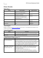
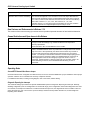
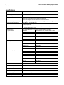
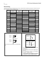
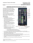
PACSystems* RX3i
IC695ALG600-DD
GFK-2348J
May 2014
Universal Analog Input Module
The PACSystems Universal Analog Input module IC695ALG600 provides eight general
purpose input channels and two Cold Junction Compensation (CJC) channels. Inputs are
divided into two equal groups of four. Channels can be individually-configured using the
Proficy* Machine Edition software for:
▪
Any combination of up to eight channels of voltage, current, thermocouple, RTD, and
resistance inputs.
▪
Thermocouple Inputs: B, C, E, J, K, N, R, S, T
▪
RTD Inputs: PT 385 / 3916, N 618 / 672, NiFe 518, CU 426
▪
Resistance Inputs: 0 to 250 / 500 / 1000 / 2000 / 3000 / 4000 Ohms
▪
Current: 0–20 mA, 4–20 mA, +20 mA
▪
Voltage: +50mV, +150 mV, 0–5 V, 1–5 V, 0–10 V, +10V
This module must be located in an RX3i Universal Backplane. An RX3i CPU with firmware
version 2.80 (Build ID 43A1) or later. Proficy Machine Edition 5.0 SP1A LD-PLC Hotfix 1 )
or later is required for configuration.
This module can be used with a Box-style (IC694TBB032), Extended Box-style
(IC694TBB132), Spring-style (IC694TBS032), or Extended Spring-style (IC694TBS132))
Terminal Block. Extended terminal blocks provide the extra shroud depth needed for
shielded wiring. See the PACSystems RX3i System Manual, GFK-2314 revision B or later
for more information about Terminal Blocks. Terminal Blocks are ordered separately.
Module Features
▪
Module supports hot insertion/extraction
▪
Terminal Block insertion or removal detection
▪
Module Status, Field Status, and TB LEDs
▪
Module meets CE, UL/CUL 508 and 1604, and ATEX requirements
▪
Flash memory for future upgrades
▪
Autocalibration at power-up
▪
Completely software-configurable, no module jumpers to set
▪
Six hardware analog-to-digital filter frequencies, individually-selectable by channel
▪
Rapid channel acquisition times based on filter frequency
▪
On-board error-checking
▪
Open-circuit detection for most input types
▪
Short-circuit detection for RTDs.
▪
User-defined scaling
▪
Module fault reporting
▪
Overrange, underrange, high alarm, low alarm, high-high alarm, low-low alarm and
calibration fault alarm detection and reporting on a per-channel basis.
▪
Positive and negative Rate of Change Alarms
▪
Configurable interrupts for channel alarms and faults
▪
Supports diagnostic point fault contacts in the logic program.
▪
CJC compensation on terminal block
▪
Temperature in Celsius or Fahrenheit
____________________________
© 2014 General Electric Company. All Rights Reserved.
*Indicates a trademark of General Electric Company and/or its subsidiaries. All other
trademarks are the property of their respective owners.
RX3i Universal Analog Input Module
2
GFK-2348J
Release Information
Release History
Release
Hardware Update
Firmware Revision
IC695ALG600-DD
This version of the product contains an
enhancement to the design that improves the
tolerance of terminal block detection.
Primary: 1.14
Boot: 1.10
IC695ALG600-DC
Label change only. No change in functionality,
performance or compatibility.
Primary: 1.11
Boot: 1.10
IC695ALG600-CC
Modified the terminal block detector switch to
increase the size of the switch lever. The
increased size of the switch lever allows
additional tolerance to assure contact with the
terminal block actuator.
Primary: 1.11
Boot: 1.10
IC695ALG600-BC
Improved noise immunity
Primary: 1.11
Boot: 1.10
IC695ALG600-AB
None
Primary: 1.10
Boot: 1.10
Initial Release
None
Primary: 1.00
Boot: 1.00
Firmware Upgrade
Revision –xA, –xB and –xC modules can be upgraded to firmware version 1.14 using upgrade kit 44A753049-G03, which is
available for downloading at http://www.ge-ip.com/support..
Functional Compatibility
Subject
Description
Programmer Version Requirements
Machine Edition Logic Developer 5.0 + Service Pack 1A with LD-PLC Hotfix 1 or
later must be used to configure and program the Universal Analog Input Module.
CPU Firmware Version
Requirements
PACSystems RX3i CPU version 2.80 or later must be used to configure and
operate the Universal Analog Input Module.
Problems Resolved in Firmware Version 1.14
Subject
Description
Accuracy of CJC on IC695ALG600
does not meet specification.
In Firmware versions 1.11 and earlier of the the IC695ALG600, channels
configured for RTD inputs that have no input connected (open wire condition)
affect the next sampled input channel. The CJC sensor is the most sensitive to this
issue, and will read about 6 °F high. Thermocouple inputs are also affected by this
issue. For example, if channels 5 and 6 are configured for T/C while 7 and 8 are
RTD with an open wire condition, channels 5 and 6 will read about 6 °F high.
When changing 7 and 8 to T/C, the channels 5 and 6 start reading the correct cold
junction compensation value. This has been corrected in version 1.14
IC695ALG600 – Thermocouple
reading oscillates between high and
low values with open circuit.
With Firmware versions 1.11 and earlier, when a thermocouple connection is left
open (that is, a channel is configured for T/C but nothing is connected to the
terminals for that channel), the values read for that T/C circuit will oscillate
between high and low values.
This has been corrected with Firmware version 1.14.
With Firmware version 1.14, if the T/C channel is left open (i.e. a channel is
configured for T/C but nothing is connected to the terminals for that channel), the
open circuit data value will be held at the Low Scale Value (Engineering Units).
RX3i Universal Analog Input Module
Subject
IC695ALG600 – Open wire
detection does not work consistently
3
GFK-2348J
Description
With firmware versions 1.11 and earlier: When channels are configured such that
T/C channels are adjacent to CJC channels in scan order, Open Wire detection
does not work consistently (That is, the designated reference bit does not get set,
or in some occurrences, the reference bit for the next T/C channel is set instead.)
Scan order is channel 1, 2, 3, 4, CJC1, then channel 5, 6, 7, 8, CJC2
Firmware version 1.14 corrects this issue and will detect an open wire condition
when T/C channels are configured adjacent (scan order) to a CJC.
New Features and Enhancements in Release 1.14
This version of the Universal Analog Input module firmware provides improved tolerance of terminal block detection.
Known Restrictions and Open Issues in this Release
Subject
Description
Temperature Offset Drift
The module exhibits offset drift with temperature. On some channels, this is
enough to cause the readings to go outside the allowed over-temperature
accuracy specification.
Recommendation: Run an autocalibration on the module.
Incorrect Display of Deadband limits
When changing configurations from one input type to another in Proficy Machine
Edition, the deadband limits and/or the positive rate of change limits for the module
may be incorrect. More specifically, the values for these limits may increase or
become invalid each time the configuration is switched from one input type to
another. For example, if Fahrenheit is selected for a thermocouple input type and
the input type is then changed to voltage, the deadband limits do not change to
reflect appropriate values for the voltage input type and remain in units of
Fahrenheit. Switching back to a thermocouple input type could then result in all
values defaulting to Celcius, but the deadband limits remaining in units of
Fahrenheit.
Operating Notes
Unused RTD Channels Must Have a Jumper
Channels that have been configured as an RTD channel, but are not connected must have a jumper installed to assure proper
operation. Failure to do so could affect the accuracy of adjacent channels.
For additional information, including a wiring diagram, refer to the section, Module Wiring.
Diagnostic Reporting for Interrupts
The Universal Analog Input module has separate enable/disable options for Diagnostic Reporting and Interrupts. Normally,
disabling a diagnostic (such as Low/High Alarm or Over/Under range) in the configuration means that its diagnostic bit is never
set. However, if interrupts are enabled for a condition and that interrupt occurs, the diagnostic bit for that condition is also set
during the same PLC scan. The next PLC input scan always clears this interrupt status bit back to 0, because Diagnostic
Reporting has it disabled.
RX3i Universal Analog Input Module
4
GFK-2348J
Specifications
Backplane Power Requirements
300 mA maximum @ 5.0V
320 mA maximum @ 3.3V
Power Dissipation within Module
Thermal Dissipation
5.4 watts maximum
LEDs
One green LED to indicate the module status
One bi-color green/yellow LED to indicate the field status
One bi-color red/green LED to indicate the terminal block status
Per Channel Acquisition Time (Each 10 msec @ 1000 Hz, 13 msec @ 200 Hz, 27 msec @ 40 Hz, 67 msec @ 16 Hz, 87
group scanned independently)
msec @ 12 Hz, 127 msec @ 8 Hz
Channel Update Time
The sum of the channel acquisition times for a bank of 4 channels plus one of the
following if applicable:
1. RTD Lead resistance measurement time (equals channel acquisition time)
2. CJC acquisition time 7 msec.
Input resolution
11 to 16 bits, depending on configured range and A/D filter frequency.
Resistance
0-250, 0-500, 0-1000, 0-2000, 0-3000, 0-4000
Inputs in Ohms
RTD Inputs
Thermocouple Inputs
Platinum 385
100, 200, 500,1000
Platinum 3916
100, 200, 500,1000
Nickel 672
120
Nickel 618
100,200, 500,1000
Nickel-Iron 518
604
Copper 426
10
Copper 426
-100 to 260°C
Nickel 618
-100 to 260°C
Nickel 672
-80 to 260°C
Nickel-Iron 518
-100 to 200°C
Platinum 385
-200 to 850°C
Platinum 3916
-200 to 630°C
Type B
300 to 1820°C
Type C
0 to 2315°C
Type E
-270 to 1000°C
Type J
-210 to 1200°C
Type K
-270 to 1372°C
Type N
-210 to 1300°C
Type R
0 to 1768°C
Type S
0 to 1768°C
Type T
-270 to 400°C
Voltage Inputs
-10V to +10V, 0V to +10V, 0V to +5V, 1V to +5V, -50mV to +50mV, -150mV to
+150mV
Current Inputs
-20mA to +20mA, 4 to 20mA, 0 to 20mA
Configurable Input Filter
8 Hz, 12 Hz, 16 Hz, 40 Hz, 200 Hz, 1000 Hz
Scaling
Floating point user scaling.
Max RTD Cable Impedance
25 ohm
RTD Wire Length
1000 ft max w/settling time of 1mSec
Input Impedance
>1M ohm for TC/V/RTD
Current Input Resistance
249 ohm +/- 1%
RX3i Universal Analog Input Module
5
GFK-2348J
Open circuit detection time
5 seconds max. Open circuit detection is available for all configurations except +/20mA current, 0-20mA current, and +/-10V voltage.
Max Overvoltage
+/-14.5VDC continuous
Max Overcurrent
28 mA continuous
Normal Mode Noise Rejection
95 dB minimum @ 50/60 Hz with 8 Hz filter
85 dB minimum @ 50/60 Hz with 12 Hz filter
Common Mode Noise Rejection
120dB minimum @ 50/60 Hz with 8 Hz filter
110dB minimum @ 50/60 Hz with 12 Hz filter
Settling time to 5% of Full Scale
(notch filter dependent)
<80 mS
Calibrated Accuracy at 25°C
Better than 0.1% of range (except 10 ohm CU RTD)
Accuracy depends on A/D filter, data format, input noise, and ambient
temperature.
Calibration interval
12 months typical to meet accuracy specifications over time. Module will allow for
user offset to be applied as a periodic calibration adjustment.
Input Offset Drift with Temperature
3.0 milliohm/°C maximum
2.0 uV/°C maximum
Gain Drift with Temperature
50 ppm/°C typical (90 ppm/°C maximum)
Module error over Full Temp range
0.5% of range typical (depends on range)
1.0% of range maximum
Module Scan Time
(notch filter dependent)
(Assumes 2 ADC’s running in parallel, no CJC or lead resistance)
10 ms per Channel × 4 Channels = 40 ms (1K Hz filter)
127 ms per Channel × 4 Channels = 508 ms (8 Hz filter)
Channels that are disabled are not scanned, shortening scan time.
Module conversion method
Sigma-delta
Isolation Voltage
channel to channel
group to group
terminal block to
backplane/chassis
Opto-isolated, transformer isolated
+-12.5Vdc channel to channel Tc/V/I/RTD
250 VAC continuous/1500 VAC for 60 seconds
250 VAC continuous/1500 VAC for 60 seconds
LEDs
The Module OK LED indicates module status. The Field Status LED indicates the presence of a fault on at least
one channel or a terminal block error. The TB (Terminal Block) LED indicates the presence or absence of the
terminal block. LEDs are powered from the backplane power bus.
LED
Module OK
Field Status
TB
Indicates
ON Green: Module OK and configured.
Slow Flashing Green or Amber: Module OK but not configured.
Quick Flashing Green: Error.
OFF: Module is defective or no backplane power present
ON Green: No faults on any enabled channel, and Terminal Block is present.
ON Yellow: Fault on at least one channel.
OFF: Terminal block not present or not fully seated.
ON Red: Terminal block not present or not fully seated.
ON Green: Terminal block is present.
OFF: No backplane power to module.
RX3i Universal Analog Input Module
6
GFK-2348J
Module Wiring
The table below lists wiring connections for the module. Except for RTD and resistance type inputs, channels are wired as
differential inputs. There are no shield terminals.
TC / Voltage /
Current
RTD or Resistance
1
CJC1 IN+
Channel 1 EXC+
2
CJC1 IN-
Channel 1 IN+
Channel 2 IN+
Channel 1 IN-
Channel 2 iRTN
Channel 3 EXC+
Channel 2 IN -
Channel 3 IN+
Terminal
RTD or
Resistance
3
Channel 2 EXC+
4
Channel 2 IN+
5
6
Channel 2 IN-
7
Channel 4 EXC+
8
Channel 4 IN+
9
10
Channel 4 IN-
11
Channel 6 EXC+
12
Channel 6 IN+
13
14
Channel 6 IN-
15
Channel 8 EXC+
16
Channel 8 IN+
17
18
Channel 8 IN-
Channel 4 IN+
Channel 3 IN-
Channel 4 iRTN
Channel 5 EXC+
Channel 4 IN -
Channel 5 IN+
Channel 6 IN+
Channel 5 IN-
Channel 6 iRTN
Channel 7 EXC+
Channel 6 IN-
Channel 7 IN+
Channel 8 IN+
Channel 7 IN-
Channel iRTN
Channel iRTN
19
Channel 1 IN+
20
Channel 1 iRTN
21
Channel 1 IN -
22
23
Channel 3 IN+
24
Channel 3 iRTN
25
Channel 3 IN-
26
27
Channel 5 IN+
28
Channel 5 iRTN
29
Channel 5 IN-
30
31
32
Channel 7 iRTN
33
Channel 7 IN-
34
Channel 8 iRTN
CJC2 IN+
35
Channel 8 IN-
CJC2 IN-
36
RTD / Resistance
Current Input
2 Wire RTD or Resistor
I
Channel EXC+
Channel IN+
Channel INChannel IN+
Terminal
Channel 7 IN+
Thermocouple / Voltage / Current
Channel IN+
TC / Voltage /
Current
Channel IN-
Voltage Input
V
3 or 4 Wire RTD or Resistor
Channel IN-
For current inputs, tie the Return to the associated INpin.
Channel EXC+
Excitation
Channel IN+
Sense +
Channel IN-
RTD Return
Sense Negative sense not connected on 4-Wire RTD
▪
▪
▪
▪
For 2 wire RTDs, tie EXC+ and IN+ together at the
terminal block.
For 4 wire RTDs, leave one of the negative sense
leads off.
For 3 wire RTDs, IN+ = Sense+, IN- = RTD Return,
and EXC+ = Excitation current.
Unconnected RTD channels must have a jumper
installed to assure proper operation. Failure to do so
could affect the accuracy of adjacent channels.
RX3i Universal Analog Input Module
7
GFK-2348J
Installing CJC Sensors
When using any thermocouple inputs on this module, the use of CJC sensors is
recommended. Installing one CJC sensor will greatly improve the accuracy of
thermocouple readings. Installing two CJC sensors will provide the highest
thermocouple input accuracy for the module. Refer to GFK-2314, PACSystems
RC3i System Manual, the section, CJC Scan Enable (Revision A or later) for
information about configuring and using CJC sensors. A CJC sensor compensates
for offset voltages introduced into the input signal where the thermocouple wires
are connected to the module. A set of two CJC sensors is available as part number
IC695ACC600.
CJC1 IN+
CJC1 IN-
Thermistor
End
CJC Sensor
Using both CJCs provides highest thermocouple compensation accuracy. Using
only CJC1 lowers the thermocouple compensation accuracy, but can improve scan
time for channels 5-8. Using only CJC2 lowers the thermocouple compensation
accuracy, but can improve scan time for channels 1-4.
CJC2 IN+
CJC2 IN-
Spring-style Terminal Block
The thermistor end of the CJC sensor must be installed in the CJC1 IN+ or CJC2 IN+ terminal for accurate temperature
measurements. The gold pin end of the CJC sensor must be installed in the CJC1 IN- or the CJC2 IN- terminal.
Open the Terminal Block contacts fully before installing the CJC sensor. Insert the sensor into the Terminal Block contact,
maintaining metal-to-metal contact between the thermistor and the Terminal Block contact.
For a Box-style Terminal Block, maintain pressure while screwing down the contact.
Isolated Input Groups
This module provides two isolated groups of four input channels each. This allows fast inputs and slower or highly-filtered
inputs to be connected to the same module without adversely affecting the update rate of the fast inputs. To take advantage of
this feature, up to four inputs requiring fast response should be placed together in one isolated group while slower inputs
should be connected to the other isolated group. For example, voltage and current inputs with higher frequency input filter
settings should be grouped together on one of the isolated groups while thermocouple, RTD, resistance, or voltage/current
inputs with low-frequency input filter settings should be grouped together on the other isolated group.
Each isolated group provides a CJC input. The CJC input is considered a slow-response input and will reduce the update rate
for the associated channel group when enabled.
Connecting Channels to the Same Thermocouple Point
When connecting one or more channels from channels 1–4 and one or more channels from channels 5 - 8 to the same
thermocouple point electrically, the point should be grounded. It can be grounded at either the sensor or the module, by adding
a jumper wire from frame ground to the low side of one thermocouple input.
Resolution and Update Time
The actual resolution and update time for each input depend on the channel’s configured Range Type and A/D Filter
Frequency, as described in GFK-2314, RX3i System User’s Manual. At higher Filter Frequencies, channel update time
increases while input resolution decreases. The approximate number of bits for each Filter Frequency and Range Type are
shown in the table below.
Filter
Frequency
8 Hz
12 Hz
16 Hz
40 Hz
200 Hz
1000 Hz
Range Type: Voltage / Current
Approximate Number of Bits
16
16
16
16
14
11
Range Type: TC / mV
Approximate Number of Bits
16
16
16
14
13
11
Channel Update
Time
127 ms
87 ms
67 ms
27 ms
13 ms
10 ms