1
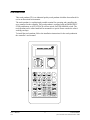
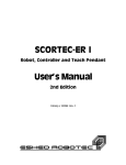
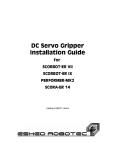
Download provided by eLABZ.com
the information source for CNC,
Robotics, Microcontroller and other
electronics projects
http://elabz.com/
6GCEJ"2GPFCPV
HQT"%QPVTQNNGT/2%"CPF"%QPVTQNNGT/75$
7UGTIU"/CPWCN
Catalog #100119 Rev.B
Copyright © 2001 intelitek
July 2001
Catalog #100119 Rev. B
Every effort has been made to make this book as complete and accurate as possible.
However, no warranty of suitability, purpose, or fitness is made or implied. Intelitek is
not liable or responsible to any person or entity for loss or damage in connection with or
stemming from the use of the software, hardware and/or the information contained in
this publication.
Intelitek bears no responsibility for errors which may appear in this publication and
retains the right to make changes to the software and manual without prior notice.
intelitek
444 East Industrial Park Dr.
Manchester, NH 03109-5317
USA
Tel: 603-625-8600
Tel: 800-777-6268
Fax: 603-625-2137
website: www.intelitek.com
email: [email protected]
Table of Contents
Introduction . . . . . . . .
Operation . . . . . . . . .
Mounted TP . . . . .
Hand-Held TP . . . .
AUTO/TEACH Switch
TP Transition . . . .
Dead Man Button . .
Emergency Button . .
Keypad Functions . . . .
Display Panel . . . . . .
Messages . . . . . .
Commands . . . . .
Status Report . . . .
TP Messages . . . . . .
User’s Manual
0107
.
.
.
.
.
.
.
.
.
.
.
.
.
.
.
.
.
.
.
.
.
.
.
.
.
.
.
.
-5-
.
.
.
.
.
.
.
.
.
.
.
.
.
.
.
.
.
.
.
.
.
.
.
.
.
.
.
.
.
.
.
.
.
.
.
.
.
.
.
.
.
.
.
.
.
.
.
.
.
.
.
.
.
.
.
.
.
.
.
.
.
.
.
.
.
.
.
.
.
.
.
.
.
.
.
.
.
.
.
.
.
.
.
.
.
.
.
.
.
.
.
.
.
.
.
.
.
.
.
.
.
.
.
.
.
.
.
.
.
.
.
.
.
.
.
.
.
.
.
.
.
.
.
.
.
.
.
.
.
.
.
.
.
.
.
.
.
.
.
.
.
.
.
.
.
.
.
.
.
.
.
.
.
.
.
.
.
.
.
.
.
.
.
.
.
.
.
.
.
.
.
.
.
.
.
.
.
.
.
.
.
.
.
.
.
.
.
.
.
.
.
.
.
.
.
.
.
.
.
.
.
.
.
.
.
.
.
.
.
.
.
.
.
.
.
.
.
.
.
.
.
.
.
.
.
.
.
.
.
.
.
.
.
.
.
.
.
.
.
.
.
.
.
.
.
.
.
.
.
.
.
.
.
.
.
.
.
.
.
.
.
.
.
.
.
.
.
.
.
.
.
.
.
.
.
.
.
.
.
.
.
.
.
.
.
.
.
.
.
.
.
.
.
.
. 7
. 8
. 8
. 8
. 8
. 9
. 9
. 9
10
16
16
16
16
18
Teach Pendant
for Controller-PC and Controller-USB
Introduction
This teach pendant (TP) is an industrial quality teach pendant which has been tailored for
use in an educational environment.
The teach pendant is a sophisticated portable terminal for operating and controlling the
axes connected to the controller This teach pendant is equipped with an EMERGENCY
STOP push button, an AUTO/TEACH selector switch, and a DEADMAN switch. The
teach pendant can be either hand-held or mounted in a special fixture outside the robot’s
working envelope.
To install the teach pendant, follow the installation instructions for the teach pendant in
the controller’s user manual.
User’s Manual
0107
-7-
Teach Pendant
for Controller-PC and Controller-USB
Operation
L Make sure the teach pendant is properly connected to the controller before you power on
the system.
The teach pendant can be either hand-held or mounted in a special fixture.
The Auto/Teach switch on the teach pendant must be in the TEACH position to enable
the teach pendant full control of the axes.
The Dead Man button and the Emergency button ensure operator safety.
Mounted TP
When the teach pendant is mounted in its special fixture, two magnetic switches are
activated by means of magnetic strips on the fixture.
Some controllers allow programs to be executed from the teach pendant, but only when
the teach pendant is mounted in this fixture. Although SCORBASE programs cannot be
executed from the teach pendant, mounting the TP is recommended, since it ensures that
the operator is safely out of the robot’s working envelope.
Hand-Held TP
When the teach pendant is hand-held, the Dead Man button must remain depressed at all
times for teach pendant operation; if this button is released, the TP is inoperative. This
restriction is for safety reasons.
AUTO/TEACH Switch
When this switch is in the TEACH position, the TP has full control of
the axes. SCORBASE commands and functions which affect axis
movement (such as the Control On icon, program execution, the Go to
Position command, or the Manual Movement dialog box) cannot be
activated from SCORBASE. All other SCORBASE functions remain
available.
When the switch is in the AUTO position, the TP is disabled, and
SCORBASE has full control of the axes.
If the switch is moved from AUTO to TEACH while programs are running, execution is
aborted.
Teach Pendant
for Controller-PC and Controller-USB
-8-
User’s Manual
0107
TP Transition
If the TP is put into or removed from the mount while the switch is in the AUTO
position, system operation is not affected.
If the TP is put into the mount while the switch is in the TEACH position, system
operation is not affected.
If the TP is put into the mount while the switch is in the TEACH position and the Dead
Man button does not remain depressed, all axes will be stopped and the TP will become
inoperative.
Dead Man Button
The Dead Man button is an elongated switch on the left side of the TP, as
shown in the diagram here.
When the teach pendant is hand-held (in TEACH mode), this button
must remain depressed at all times to enable control the axes from the TP.
If the Dead Man button is released when the TP is hand-held TP (in
TEACH mode), all axes will be stopped and the TP will be inoperative.
Emergency Button
The emergency button is the red mushroom button on the face of the
TP, and functions the same as the emergency button on the controller.
The emergency button can be activated regardless of the TP’s location
(mounted or hand-held) or status (TEACH or AUTO mode). Press the
button to activate; pull it out to release.
When the button is pressed, the system goes into the Emergency state.
To cancel the Emergency state from the TP, release the emergency
botton (if it has been pressed), and press the teach pendant’s CONTROL
ON/OFF key.
User’s Manual
0107
-9-
Teach Pendant
for Controller-PC and Controller-USB
Keypad Functions
The teach pendant’s keypad has 25 color-coded keys. Most of the keys are
multi-functional; for example, some keys include both an axis drive command and a
numeric function. The controller recognizes the keys from the order in which they are
pressed. Thus, the numeric function will be active only if a function such as SPEED or
MOVE has been keyed in first; otherwise, the axis drive command will be active.
TP commands can be executed only
when the TP is in the TEACH mode
and either the Dead Man button is
depressed or the TP is mounted.
Following are descriptions of the teach
pendant’s keys and instructions for
activating them. Bulleted items indicate
the different functions of
multi-functional keys.
ENTER / EXECUTE
•
Accepts and/or executes the
command which has been entered.
This key must remained pressed until an
axis movement is completed.
JOINTS / XYZ / TOOL
TOOL is not available
• Selects the coordinate system for command execution.
Successively press for Joints, Cartesian (XYZ) and again for Joints, and so on.
(TOOL is not available.)
Depending on the active coordinate system:
• Manual movements of the axes are executed according to Joint or XYZ coordinates.
• The TP’s Record Position command records positions in either Joint or XYZ
coordinates.
Teach Pendant
for Controller-PC and Controller-USB
-10-
User’s Manual
0107
CLR / GROUP SELECT
• CLR clears a partially entered command.
• GROUP SELECT is not available in the TP.
The axis groups A (robot axes), B (peripheral axes) and G (gripper) are automatically
activated when axis number is selected.
+
•
•
•
In Joint mode, moves the selected axis in positive direction.
In XYZ mode, moves the TCP (tool center point) in positive direction.
If axis 6/group G is selected, opens the gripper in small increments.
In all of the above, movement will continue as long as the + key is depressed, or until
the axis limit is reached.
–
•
•
•
In Joint mode, moves the selected axis in negative direction.
In XYZ mode, moves the TCP (tool center point) in negative direction.
If axis 6/group G is selected, closes the gripper in small increments.
In all of the above, movement will continue as long as the – key is depressed, or until
the axis limit is reached.
0 / SELECT AXIS
• Numerical key 0.
• Selects an axis, and activates the control group to which the axis belongs.
This key is meant to allow the selection of axis 10, 11 and 12 in controllers which
provide control of that many axes.
Although the SELECT AXIS key is available, it is not normally needed. The TP
continuously shows an axis selection prompt. You need only to press a number key to
select an axis.
• When axis 1, 2, 3, 4 or 5 is selected, Group:A is displayed.
• When axis 6 is selected, Group:G (gripper) is displayed.
• When axis 7 or 8 (if configured) is selected, Group:B is displayed.
Entering a different number will change the axis selected.
1 / AXIS 1 / X
• Numerical key 1.
• Axis 1 in Joint mode.
• Axis X in XYZ mode.
User’s Manual
0107
-11-
Teach Pendant
for Controller-PC and Controller-USB
2 / AXIS 2 / Y
• Numerical key 2.
• Axis 2 in Joint mode.
• Axis Y in XYZ mode.
3 / AXIS 3 / Z
• Numerical key 3.
• Axis 3 in Joint mode.
• Axis Z in XYZ mode.
4 / AXIS 4
• Numerical key 4.
• Axis 4 in Joint mode.
• Pitch Axis in XYZ mode.
5 / AXIS 5
• Numerical key 5.
• Axis 5 in Joint mode.
• Roll Axis in XYZ mode.
6 / AXIS 6
•
•
Numerical key 6.
Axis 6 / Gripper in Joint and XYZ modes.
7 / AXIS 7
• Numerical key 7.
• Axis 7 in Joint mode (only if axis installed and configured.)
8 / AXIS 8
• Numerical key 8.
• Axis 8 in Joint mode (only if axis installed and configured.)
9 / AXIS 9
• Numerical key 9.
• Axis 9 cannot be installed or configured.
Teach Pendant
for Controller-PC and Controller-USB
-12-
User’s Manual
0107
CONTROL ON/OFF
Enables and disables control of the selected group, or all groups.
• If pressed once, toggles the CON/ COFF state for the selected group.
• If pressed twice, changes CON and COFF for all axis control groups.
If at least one group is in CON mode, COFF is applied to all groups.
If all groups are in COFF mode, CON is applied to all groups.
The action to be performed (e.g., COFF GROUP B, CON ALL GROUPS) will be
displayed.
Press Enter to accept.
Selecting an axis from the TP (axis number keys) automatically enables control of the
group to which the axis belongs.
If axis 6 is selected, GROUP G is displayed and the CON/COFF toggle applies only to
the gripper.
RECORD POSITION
This command defines and records absolute positions. Positions are attached to an array
which is associated with either the robot axes (SCORA) or the peripheral axes (SCORB).
Up to 100 SCORBASE positions can be recorded from the TP.
•
•
Press Record Position.
A position array name is displayed; depending on the active control group, it is either
SCORA_ or SCORB_ . If Group G is active, the position will be recorded in the
SCORA array.
Enter a number, from 1 to 100, and press Enter.
When recorded, a position receives the current coordinates of the axes in the selected
group. The coordinates are recorded in the currently active coordinate system.
If you enter the number of a position which has already been recorded, new
coordinates will overwrite the existing ones.
The same number can be used for positions in both the SCORA and the SCORBA
arrays (e.g., SCORA10 and SCORB10.)
INSERT / DELETE
This command is not available.
User’s Manual
0107
-13-
Teach Pendant
for Controller-PC and Controller-USB
SPEED(%) / SPEEDL (%)
Sets the speed of manual axis movement, as a percentage of maximum speed.
SPEEDL (%) is applicable to the robot axes only.
Do not attempt to use SPEEDL when Group B is selected.
•
•
If in Joint mode, sets the percentage of maximum joint speed.
SPEED is displayed.
If in XYZ mode, sets the percentage of maximum linear speed.
SPEEDL is displayed.
Press SPEED(%)/SPEEDL(%). The current speed is displayed.
Press Enter to accept the displayed default speed. Or use the numerical keys to enter a
different speed, and press Enter.
OPEN / CLOSE
Completely opens and completely closes the gripper.
MOVE / MOVEL
Moves the axes to a target position.
MOVEL is applicable to the robot axes only.
Do not attempt to use MOVEL when Group B is selected.
• If in Joint mode, movement is by joints (MOVE)
• If in XYZ mode, robot movement is linear (MOVEL)
Press MOVE/MOVEL. Then use the numerical keys to enter the position number.
Press and hold the Execute key. Continue holding down the Execute key until the
axes reach the target position. If the Execute key is released, the movement is stopped
immediately, and the command is aborted.
• The command MOVE 0 moves the axes of the currently active group to their home
position.
MOVE SCORA0 executes the Go Home - Robot command.
MOVE SCORB0 executes the Go Home - Peripherals command.
Teach Pendant
for Controller-PC and Controller-USB
-14-
User’s Manual
0107
SPLINE / MOVEC
Moves the robot axes to a target position through an intermediate position.
SPLINE / MOVEC is applicable to the robot axes only.
Do not attempt to use this key when Group B is selected.
•
•
If pressed once, a SPLINE movement will be executed.
If pressed twice, a MOVEC movement will be executed.
Use the numerical keys to enter the first (“ through” ) position number, and press
Enter.
Use the numerical keys to enter the second (target) position number.
Then press and hold the Execute key.
Continue pressing the Execute key until the axes reach the target position. If the
Execute key is released, the movement is stopped immediately, and the command is
aborted.
RUN
SCORBASE programs cannot be executed from the teach pendant.
The one exception is the command RUN 0:
• If Group A is selected, RUN 0 executes the Search Home - Robot command.
• If Group B is selected, RUN 0 executes the Search Home - Peripherals command.
Use the EMERGENCY button, if necessary, to abort the homing.
SINGLE STEP
This command is not available.
ABORT
This command is not available.
To abort a movement, you need only to stop pressing the Enter/Execute or +/– key, or to
release the Dead Man switch in order to abort a movement.
User’s Manual
0107
-15-
Teach Pendant
for Controller-PC and Controller-USB
Display Panel
The teach pendant has a four-line liquid crystal display panel. Each line displays a
specific type of message or text.
Messages
When the TP is in either the TEACH mode or AUTO mode, line 1 displays system and
error messages. The current display is erased when a new message appears.
When the TP is in the AUTO mode, lines 2, 3 and 4 will display:
TP IN AUTO MODE
A list and brief descriptions of TP messages appear in the next section.
Commands
When the TP is in the TEACH mode, lines 2 and 3 display commands.
Line 2 displays the last command entered. Subsequent commands are scrolled into Line 2.
Line 3 displays the command currently being entered, and serves as a user interface.
Status Report
When the TP is in the TEACH mode, line 4 displays the current status of the axes, in the
following format:
group:g AX: xx cccccc
When the text in line 4 is displayed normally (black on white), it indicates Control ON
(CON) for the group displayed.
When the test in line 4 is displayed inversely (white on black), it indicates Control OFF
(CON) for the group displayed.
g is the currently selected axis control group (if exists):
A: control group A
G: gripper
B: control group B
xx is the currently active joint or axis in the active group:
1-8: joint
X : X axis
Y : Y axis
Z : Z axis
P : Pitch axis
R : Roll axis
Teach Pendant
for Controller-PC and Controller-USB
-16-
User’s Manual
0107
cccccc is the currently active coordinate system:
Joint
XYZ
Examples
GROUP:B AX:7 JOINTS
Group B, Axis 7 is active, Joint mode, in COFF state.
GROUP:A AX:P XYZ
Group A, Pitch axis is active, XYZ mode, in CON state.
User’s Manual
0107
-17-
Teach Pendant
for Controller-PC and Controller-USB
TP Messages
The following are system messages which may appear on line 1 of the teach pendant
during manual operation and program execution. Comparable messages may also appear
on the SCORBASE screen.
B WORKSPACE
The position cannot be reached. The movement cannot be executed.
COMMAND NOT ALLOWED
The command is invalid for the current axis configuration.
CONFIGURATION CHANGE
The movement cannot be executed from the robot’s current location.
CONTROL DISABLED
Motors have been disconnected from servo control (COFF).
EMERGENCY
The emergency switch has been pressed.
ERROR
FATAL ERROR
SYSTEM ERROR
The system is unable to execute the command.
HOME NOT DONE
You attempted to move the arm to a recorded positions, or to record a position,
before homing was performed on the group or axis.
HOMING AXIS n . . .
Displayed while homing routine is being performed. n indicates the specific axis
which is being homed at the moment.
HOMING COMPLETE
Displayed very briefly when homing routine is completed.
IMPACT
The system has detected a position error which is too large. The system aborted all
movements, and disabled the axes.
This message appears if you attempt to move an axis which is configured but not
physically present.
INVALID AXIS
The selected axis is not configured (e.g., axis 9).
Teach Pendant
for Controller-PC and Controller-USB
-18-
User’s Manual
0107
JOINT WORKSPACE
The robot is at a position at which the Joints coordinate system is not supported.
The position could not be recorded or reached because its Joints coordinates are out
of the Joints work envelope.
MOTION ABORTED
Axis movement has stopped. This happens when you stop pressing the Enter/Execute
or +/– key, or release the Dead Man switch during a movement. To complete the
command, it must be entered again.
MOTION WORKSPACE
The MOVEL command cannot be executed.
MOTION COMPLETED
The movement was successfully completed.
NO AXIS SELECTED
The command could not be executed because an axis has not been specified
(selected).
NOT ACTIVE
The function or command is not available on the teach pendant.
THERMIC OVERLOAD
The system has detected a dangerous condition for the motor. The system aborted all
movements and disabled the axes.
TP IN AUTO MODE
The teach pendant’s switch is set to AUTO. SCORBASE has control of the axes.
TP IN TEACH MODE
The teach pendant’s switch is set to TEACH. The teach pendant has control of the
axes.
UNASSIGNED POINT
The specified position has not been recorded, or it has not been recorded for the
currently selected axis group.
XYZ WORKSPACE
The robot is at a position at which the XYZ coordinate system is not supported.
The position could not be recorded or reached because its XYZ coordinates are out of
the XYZ work envelope.
User’s Manual
0107
-19-
Teach Pendant
for Controller-PC and Controller-USB