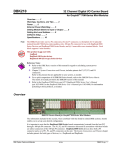
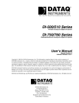
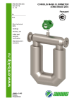
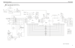
1
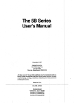
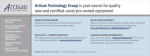
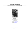
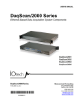
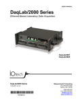
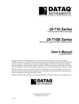
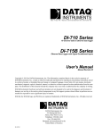
DBK207 and DBK207/CJC
5B Carrier Boards
For 5B-Compatible Analog Input Modules
Overview …… 1
Warnings, Cautions, and Tips ……. 3
Power Considerations …… 4
External Ground Connection …… 4
Channel Configuration …… 5
5B Module Connection …… 5
Terminal Block Connection …… 6
Connecting DBK207 or DBK207/CJC to a Daq Device …… 7
Software Setup …… 7
DBK207 and DBK207/CJC – Specifications …… 8
Note:
The DBK207 and DBK207/CJC each provide: (a) two P1 connectors, (b) footprints for sixteen 5B
Modules, (c) 16 terminal blocks. In addition, DBK207/CJC provides Cold Junction Compensation.
The DBK207 and DBK207/CJC each include a 100-pin P4 connector for use with DaqBoard/2000
Series and cPCI DaqBoard/2000c Series Boards, and DaqBook/2000 Series devices.
This product is not used for LogBook applications.
Reference Notes:
In regard to calculating system power requirements refer to the DBK Basics section.
For information regarding a related product with a different form-factor, refer to the
DBK44, 2-Channel 5B Signal-Conditioning Card section of this manual.
Chapter 2 includes pinouts for P1, P2, P3, and P4. Refer to pinouts applicable to your
system, as needed.
For a quick comparison of all DBK200 Series boards, refer to the DBK200 Series Matrix.
The matrix is located just before the DBK200 section.
Refer to the DaqBoard/2000 Series and cPCI DaqBoard/2000c Series User’s Manual
(p/n 1033-0901) or the DaqBook/2000 Series User’s Manual (p/n 1103-0901) for information
pertaining to those products, as needed.
Overview
The DaqBoard/2000 Series and cPCI DaqBoard/2000c Series boards communicate [external from the host
PC] through a 100-pin P4 connector. The P1, P2, and P3 connectors discussed in association with
DaqBoard/2000 Series and cPCI DaqBoard/2000c Series boards are subset connectors of the 100-pin P4
connector that is located on those boards. Chapter System Connections and Pinouts, includes pinouts for
P1, P2, P3, and P4.
DBK207/CJC Carrier Board for 5B Compatible Modules
DBK Option Cards and Modules
987594
DBK207 and DBK207/CJC, pg. 1
WARNING
Ensure that hard-wire emergency over-ride circuitry exists for all applications that
make use of dangerous switch-loads. Do not operate such switch-loads unless
emergency over-ride circuitry is present.
The DBK207 and DBK207/CJC are carrier boards for 5B-compatible analog input modules. These options
each include two P1 connectors for analog expansion, a 5 VDC power terminal, and 16 signal terminal
blocks. DBK207 and DBK207/CJC are typically installed in NEMA-type panels; however, they may be
installed on DIN rails. Separate mounting instructions are included with Rack Mount Kit (part no.
Rack-DBK-3) and with DIN-rail Mount Kit (part no. DIN-DBK-1).
DBK207 and DBK207/CJC allow Daq-based acquisition systems to use various combinations of sixteen
5B signal-conditioning modules. 5B modules can accommodate a variety of signals, including low-level
thermocouple and strain-gage signals. Configuration options are flexible. You can select the type of signal
attached to each channel. One Daq device can support up to 16 DBK207 [or DBK207/CJC] boards,
providing a maximum of 256 isolated, analog input channels. Note that Daq devices scan the channels at
the same 10 µs/channel rate as other DBKs (256 scans in 2.56 ms in a full system).
Each user-installed 5B module offers 500 V isolation from the system and between channels. Both
DBK207 and DBK207/CJC include 16 screw-terminal blocks for signal inputs. In addition, the
DBK207/CJC includes cold junction compensators (CJCs) for use with thermocouple 5B modules.
Sockets are provided for user-installed AC1362 current-sense resistor modules, as discussed in
5B Module Connection on page 5 of this section.
Note 1: CJC is applicable to DBK207/CJC.
CJC does not apply to DBK207.
Note 2: Current requirement is dependent
upon the 5B modules used as
discussed in Power Considerations.
Note 3: JP2 provides a means of obtaining
an external earth ground. See Power
Considerations for details.
DBK207 and DBK207/CJC Block Diagram
DBK207 and DBK207/CJC, pg. 2
987594
DBK Option Cards and Modules
Warnings, Cautions, and Tips
WARNING
Ensure that hard-wire emergency over-ride circuitry exists for all applications that
make use of dangerous switch-loads. Do not operate such switch-loads unless
emergency over-ride circuitry is present.
CAUTION
Turn off power to the host PC and externally connected equipment prior to connecting
cables or signal lines to the DBK. Electric shock or damage to equipment can result
even under low-voltage conditions.
Take ESD precautions (packaging, proper handling, grounded wrist strap, etc.)
Use care to avoid touching board surfaces and onboard components. Only handle
boards by their edges (or ORBs, if applicable). Ensure boards do not come into contact
with foreign elements such as oils, water, and industrial particulate.
Do not confuse connectors. Ensure that you only connect P1 I/Os to P1,
P2 I/Os to P2, and P3 I/Os to P3. Improper connection may result in equipment
damage.
1.
Ensure that hard-wire emergency over-ride circuity exists for all applications that make use of
dangerous switch-loads. Do not operate such switch-loads unless emergency over-ride circuitry is
present.
2.
Provide raceways (protective wiring routes) for all external I/O wiring.
3.
Keep external I/O wiring away from ribbon cables.
4.
Keep external I/O wiring away from low-voltage signal wiring.
5.
Provide appropriate strain-relief and physical restraint to ensure that the wiring is held securely in the
intended position, and without strain.
6.
Ensure that all wiring with >50V potential is identified by the appropriate color codes and that
warning labels are clearly visible.
7.
Provide physical protection for the interface board. The level of protection is dependent upon the
board’s operating environment.
Partial DBK207/CJC
DBK Option Cards and Modules
987594
DBK207 and DBK207/CJC, pg. 3
Power
The DBK207 and DBK207/CJC require +5 VDC from a regulated DC power supply. External power
attaches to the DBK207 [DBK207/CJC] via on-board screw terminal connections.
Power Requirements:
Voltage: +5 V regulated DC
Current: Dependent upon 5B Models used.
• SC-5B38 series modules each require 200 mA.
• SC-5B43 series modules require up to 200 mA.
• All other analog input 5B modules require 30 mA, unless otherwise specified.
On-Board Power Connections for +5 Volts
CAUTION
External power supplied to DBK207 or DBK207/CJC must not exceed +5 VDC.
Neither DBK207 nor DBK207/CJC regulate the external power input.
External Ground Connection
For optimum 5B module operation, the 5B must have one [and only one] earth ground. Accordingly, the
DBK207 [DBK207/CJC] must be configured to provide its earth ground, if such a ground is not present on
the power supply.
JP2 Shown in OPEN Default
If the 5 VDC power supply provides output that is isolated from earth ground, then the jumper on JP2
should be placed in the CONN position. This will tie the 5V return on the power supply to the DBK207
[DBK207/CJC] ground system.
If the 5 VDC power supply is already referenced to earth ground, then the JP2 jumper should be placed to
OPEN. This will prevent multiple earth ground connections and the resultant ground loop. Note that the
OPEN position is JP2’s default setting.
DBK207 and DBK207/CJC, pg. 4
987594
DBK Option Cards and Modules
Channel Configuration
Up to 16 DBK207 [DBK207/CJC] boards can be connected to a Daq-based acquisition
system. Since this is a daisy-chain interface, each module must appear unique and use a
different analog input channel to the Daq device. To configure the board’s channel, you
must set the JP1 jumper to your chosen channel as follows.
1.
Locate the 16×2-pin header (labeled JP1). Note the 16 jumper locations labeled
CH0 through CH15 to match the Daq device’s main channel.
2.
Place the JP1 jumper on the channel you wish to use. Only one jumper is used per
board.
5B Module Connection
DBK207 and DBK207/CJC analog input is processed through user-installed 5B signal-conditioning
modules. Different 5B modules are used with different transducer and signal sources. To install the
modules:
1.
Remove all power from the DBK207 [DBK207/CJC].
2.
Match the footprint of the module with the footprint on the printed circuit board.
3.
Gently place the module into the footprint, and screw it down.
4.
Record the channel the module was placed in.
When installing current input modules (SC-5B32 series), be sure to install the currentsense resistor (SC-AC-1362 shipped with the SC-5B32) in the resistor socket near the
input screw-terminal block for the desired channel.
AC1362 Current Sense Resistor Install Location
DBK Option Cards and Modules
987594
DBK207 and DBK207/CJC, pg. 5
Terminal Block Connection
WARNING
Shock Hazard. De-energize circuits connected to the DBK207, or DBK207/CJC before
changing the wiring or configuration. Dangerous voltages may be present.
Input signals (and excitation leads) are wired to DBK207 [DBK207/CJC] via 16 four-contact terminal
blocks that connect to corresponding 5B modules. The following figures depict various connection
scenarios.
Connection Scenarios for 5B Modules
DBK207 and DBK207/CJC, pg. 6
987594
DBK Option Cards and Modules
Connecting DBK207 or DBK207/CJC to a Daq Device
DBK207 and DBK207/CJC can be connected to the P4 connector of a DaqBook/2000 Series device or a
DaqBoard/2000 Series board via a CA-195 cable or can be connected through the P1 connector of an
applicable DBK200 series adapter board via CA-37-1 accessory ribbon cables.
Software Setup
Reference Notes:
o
DaqView users - Refer to chapter 3, DBK Setup in DaqView.
o
LogView users - Not Applicable.
DaqView software versions preceding 7.7 do not provide complete software support
for the DBK207 or the DBK207/CJC carrier boards. If your version of DaqView
precedes version 7.7, you must uninstall it, then install a more recent version of
DaqView.
DBK Option Cards and Modules
987594
DBK207 and DBK207/CJC, pg. 7
DBK207 and DBK207/CJC – Specifications
Name/Function:
DBK207 – Carrier Board for 5B-Compatible Analog Input Modules
DBK207/CJC – Carrier Board (with Cold Junction Compensation) for
5B-Compatible Analog Input Modules
Module Capacity: 16, input only, 5B modules
Cable (optional): CA-37-×
DC Input Fuse: 3A, reset type
Power Requirement: 5 VDC, regulated.
Operating Environment:
Temperature: 0°C to 70°C
Relative Humidity: 95% RH, non-condensing
Connectors:
P4 – 100-pin connector provides for connection to DaqBook/2000 Series device,
DaqBoard/2000 Series board and cPCI DaqBoard/2000c Series
P4 connector via a CA-195 cable.
P1 – Two P1 (DB37) connectors provide for analog expansion via CA-37-x cable.
Screw Terminals – 16 sets of 4-connector blocks provide wire connection for
+E, -E, +, and -.
Isolation (DC or AC Peak):
Signal Inputs to Daq Device: 500 V
Input Channel-to-Channel: 500 V
CJC: Cold Junction Compensation, applicable to DBK207/CJC.
Not Applicable to DBK207.
DBK207 and DBK207/CJC, pg. 8
987594
DBK Option Cards and Modules