1
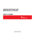
UM013 FMC645 User Manual r1.1 FMC645 User Manual 4DSP LLC, USA This document is the property of 4DSP LLC and may not be copied nor communicated to a third party without the written permission of 4DSP LLC © 4DSP LLC 2015 FMC645 User Manual www.4dsp.com -1- UM013 FMC645 User Manual r1.1 Revision History Date History Revision 2012-03-01 First draft 0.1 2012-03-06 Modifications after first review 0.2 2012-03-22 Processed all comments 1.0 2014-04-25 Added a section that describes an optional modification that is required when targeting Xilinx reference boards. 1.1 FMC645 User Manual www.4dsp.com -2- UM013 FMC645 User Manual r1.1 Table of Contents 1 2 3 4 5 6 7 8 Acronyms and related documents ........................................................................... 4 1.1 Acronyms ................................................................................................................... 4 1.2 Related Documents .................................................................................................. 4 1.3 General description................................................................................................... 5 Installation ....................................................................................................................... 5 2.1 Requirements and handling instructions ............................................................... 5 Hardware design............................................................................................................ 5 3.1 Physical Specifications............................................................................................. 6 3.1.1 Board Dimensions ............................................................................................. 6 3.1.2 Emulator Header................................................................................................ 6 3.1.3 GPIO header ...................................................................................................... 7 3.2 Fixed point DSP (TMS320C6455).......................................................................... 7 3.2.1 DDR2 SDRAM Memory .................................................................................... 8 3.2.2 EMIFA Bus.......................................................................................................... 8 3.2.3 McBSP................................................................................................................. 8 3.2.4 Serial RapidIO .................................................................................................... 8 3.2.5 PCI66 ................................................................................................................... 8 3.2.6 EMAC 10/100/1000 module ............................................................................. 9 3.2.7 GPIO .................................................................................................................... 9 3.2.8 I2C ........................................................................................................................ 9 3.2.9 Timers................................................................................................................ 10 3.2.10 Clocks and reset .......................................................................................... 10 3.2.11 Stacked FMC ................................................................................................ 11 3.2.12 JTAG .............................................................................................................. 11 3.2.13 Device Configuration ................................................................................... 12 3.3 Level translation ...................................................................................................... 13 3.4 FMC connector Pin list ........................................................................................... 13 Power characteristics................................................................................................. 19 4.1 Power monitoring .................................................................................................... 19 Environment ................................................................................................................. 20 5.1 Temperature ............................................................................................................ 20 5.2 Cooling ...................................................................................................................... 20 5.2.1 Convection cooling ............................................................................................ 20 5.2.2 Conduction cooling ............................................................................................ 20 Safety .............................................................................................................................. 21 EMC ................................................................................................................................. 21 Warranty......................................................................................................................... 21 FMC645 User Manual www.4dsp.com -3- UM013 FMC645 User Manual r1.1 1 Acronyms and related documents 1.1 Acronyms ADC BLAST DAC DCI DDR DSP EPROM FBGA FMC FPGA GPIO JTAG LEB LED LVTTL LSB LVDS MGT MSB PCB PCI PCI-e PLL QDR SBC SDRAM SOC SRAM SSP TTL Analog to Digital Converter Board Level Advanced Scalable Technology Digital to Analog Converter Digitally Controlled Impedance Double Data Rate Digital Signal Processing Erasable Programmable Read-Only Memory Fineline Ball Grid Array FPGA Mezzanine Card Field Programmable Gate Array General Purpose Input Output Join Test Action Group Local Expansion Bus Light Emitting Diode Low Voltage Transistor Logic level Least Significant Bit(s) Low Voltage Differential Signaling Multi-Gigabit Transceiver Most Significant Bit(s) Printed Circuit Board Peripheral Component Interconnect PCI Express Phase Locked Loop Quadruple Data rate Single Board Computer Synchronous Dynamic Random Access memory System On Chip Synchronous Random Access memory Synchronous Serial Port Transistor Logic level Table 1 Acronyms 1.2 Related Documents FMC Specification ANSI VITA 57.1-2010. Datasheet TMS320C6455 Rev 06/2011, Texas Instrument. Datasheet TMS320C645x DSP SRIO, Texas Instrument (SPRU976). Datasheet TMS320C6000 DSP McBSP, Texas Instrument (SPRU580). Datasheet TMS320C645x DSP EMIF, Texas Instrument (SPRU971). Datasheet TMS320C645x DSP GPIO, Texas Instrument (SPRU724a) Datasheet TXB0108 Rev 09/2011, Texas Instrument. Datasheet SN74AVC16T245 Rev 08/2005, Texas Instrument. FMC645 User Manual www.4dsp.com -4- UM013 FMC645 User Manual r1.1 1.3 General description The FMC645 is a digital signal processor FMC daughter card based on TI 1.2GHz TMS320C6455 DSP. The FMC645 daughter card is mechanically and electrically compliant to FMC standard (ANSI/VITA 57.1). The card has a high-pin count connector and can be used in a conduction cooled environment. There is no front panel I/O. The card is equipped with power supply and temperature monitoring and offers several power-down modes to switch off unused functions and peripheral interfaces. TMS320C6455 – DSP 1.2GHz EMIF A 64-bit @ 166MHz McBSP (2) 125MHz EMAC HPI RocketIO UTOPIA GPIO EMU I2C JTAG GMII 4 lanes FMC HPC 2 4 PCI66 24LC02B H E A D E R DDR2 MEM ADT7411 32-bit 66MHz PCIe 1-lane PCIe/PCI bridge DDR2 SDRAM Figure 1 FMC block diagram 2 Installation 2.1 Requirements and handling instructions The FMC645 daughter card must be installed on a carrier card compliant to the FMC standard. The FMC carrier card must support the high-pin count connector (HPC 400pins). The FMC carrier card must support VADJ/VIO_B voltage of +1.5V to +3.3V (LVCMOS/LVTTL signaling). Do not flex the card and prevent electrostatic discharges by observing ESD precautions when handling the card. 3 Hardware design FMC645 User Manual www.4dsp.com -5- UM013 FMC645 User Manual r1.1 DDR2 DDR2 3.1 Physical Specifications 3.1.1 Board Dimensions The FMC645 card fully complies with the FMC standard known as ANSI/VITA 57.1. The card is a single width conduction cooled mezzanine module (without region 1 and without front panel I/O). On the top level all the main active components and the FMC connector are placed (see Figure 2). Power Supply 12V to 1.8V DSP PCI-PCIe Bridge Power Supply 3.3V to 1.25V Figure 2 Top level floorplan On the bottom level a debug header and GPIO headers can be placed (see figure 3). TP 1V25C TP GND TP 1V25IO GPIO header 3V3 Emulator header 2 TP 3V3 TP VADJ TP 1V8 1 TP 12V Figure 3 Bottom level floorplan 3.1.2 Emulator Header The FMC645 includes a 14-pins emulator header for onboard debugging purposes. The emulator header (Part number: 223578) is a press-fit removable header located on the left corner of the bottom side (See Figure 3). FMC645 User Manual www.4dsp.com -6- UM013 FMC645 User Manual r1.1 To communicate with the emulator, the target source is two rows of seven pins. Table 2describes the Emulation signals. Pin No. 1 2 3 4 5 6 7 8 9 10 11 12 13 14 Signal Name TMS TRST# TDI GND PD No Pin TDO GND RTCK GND TCK GND EMU0 EMU1 Description TEST MODE SELECT TEST CLOCK TEST DATA INPUT PRESENT DETECT(Tied to 3.3V) TEST DATA OUTPUT TEST CLOCK RETURN TEST CLOCK EMULATION PIN 0 EMULATION PIN 1 Table 2 Emulator header pinout Note: When the debug header is placed the FMC645 board is not anymore compliant with the FMC mechanical specifications. 3.1.3 GPIO header The FMC645 offers a 6-pin header for general purpose input output with 0.100mm pitch. The header (Part name: 223080) is located on the left corner of the bottom side (SeeFigure 3). Pin No. 1 2 3 4 5 6 Signal Name 3V3 GP04 GP05 GP06 GP07 GND Table 3 GPIO header pinout 3.2 Fixed point DSP (TMS320C6455) The Texas Instruments TMS320C6455 is capable of running at 1.2GHz. It is backward compatible to older Texas Instruments DSPs and has the following external peripheral interfaces: - DDR2 Memory Controller - EMIFA FMC645 User Manual www.4dsp.com -7- UM013 FMC645 User Manual - r1.1 McBSP (2x) Serial RapidIO PCI66 EMAC 10/100/1000 GPIO I2C Timers Emulator UTOPIA (not available, dual purpose pins used for PCI66) HPI (not available, dual purpose pins used for PCI66) For more information please refer TMS320C6455 Texas Instrument datasheets. 3.2.1 DDR2 SDRAM Memory In total 512Mbytes DDR2 SDRAM memory are available on the FMC645. Two 16-bit external memory devices (MT47H128M16) with 256Mbytes density are implemented. Both external memories operate with the DDR2 memory controller of the DSP. When the EMAC is used the DDR2 bus speed is restricted to 250MHz. 3.2.2 EMIFA Bus External memory interface A connects to the FMC connector. The full 64-bit connection is implemented requiring 108 FMC connections. Data bus can also be configured to 32, 16 and 8-bits wide. An external clock (AECLKIN) has to be provided by the carrier board. It is not allowed to use the internal clock (SYSCLK4) to clock the EMIFA bus. All external memories interfacing with the EMIFA bus should operate using AECLKOUT clock. Also, it is possible to connect four external memory interface (CE2-5) for asynchronous or synchronous accesses. 3.2.3 McBSP Two McBSPs peripheral ports connect to the FMC connector providing a full-duplex communication. The McBSP consists of a data path and a control path that connect to the FMC connector. Each McBSP interface includes separate pins for transmission and reception of data. Four other pins for control information: clocking and frame synchronization. Due to dual purpose capability the McBSP1 peripheral can be disabled in order to enable the GPIO pins purpose. 3.2.4 Serial RapidIO Four SRIO transceivers are connected to gigabit IO on the FMC connector. The SRIO peripheral is a master peripheral and requires LVDS clock (REF_RIO at 125MHz) provided by a crystal oscillator on the FMC645. Special care has been taken during the hardware design in order to operate at a data rate of 3.125Gbps per differential pair. 3.2.5 PCI66 The DSP connects its PCI interface through a PCI/PCIe bridge (Pericom, PI7C9X110) to the FMC connector. The PCI/PCIe bridge is set up in transparent bridge and forward mode. The PCI bus is operating at 66MHz. There is a local clock FMC645 User Manual www.4dsp.com -8- UM013 FMC645 User Manual r1.1 source for the PCI express so the FMC645 cannot be used in environments that use Spread Spectrum Clocking. Auxiliary power management is not supported. 3.2.6 EMAC 10/100/1000 module The EMAC module provides an efficient interface between the DSP and the network community. The EMAC module conforms to the IEE802.3-2002 standard, describing the carrier sense multiple access with collision detection (CSMA/CD) specifications. The Ethernet peripheral port of the DSP connects to the FMC connector. The GMII interface is connected to the FMC connector. 3.2.7 GPIO The general-purpose input/output peripheral provides dedicated general-purpose pins that can be configured as either inputs or outputs. The DSP has a GPIO port with 16 I/O, but only a maximum of 11 are available on the FMC connector depending of the configuration of the device. A 6-Pin header is connected for control purposes (see section 0) of the GPIO[4:7]. In order to have the maximum GPIO signals available the device has to be configured as follow. FMC Signal Name SYSCLK4/GP[1] CLKX1/GP[3] FSX1/GP[11] DX1/GP[9] CLKR1/GP[0] FSR1/GP[10] DR1/GP[8] Configurations pins setting AEA4 = 0 AEA5 = 0 AEA5 = 0 AEA5 = 0 AEA5 = 0 AEA5 = 0 AEA5 = 0 Mode GP[01] GP[3] GP[11] GP[9] GP[0] GP[10] GP[8] Table 4 Dual purposes pins 3.2.8 I2C The I2C peripheral port connects to the FMC dedicated pins. The FMC645 card carries a small serial EEPROM (24LC02B) which is accessible from the carrier card through the I2C bus. It connects also to the power and temperature monitoring device (ADT7411). The FMC connector allocates two dedicated pins for the I 2C peripherals. It connects to the DSP, the power monitoring device and the EEPROM. The following table shows I2C addresses allocation. Peripheral DSP EEPROM Power Monitoring Address Software dependent 1010 XXX 1001 XXX Table 5 I2C bus addresses The EEPROM contains information about the FMC as required by the FMC standards. Customers are not allowed to make changes to the EEPROM contents. FMC645 User Manual www.4dsp.com -9- UM013 FMC645 User Manual r1.1 3.2.9 Timers The FMC645 has two general-purpose timers, Timer0 and Timer1 connected to the FMC connector, requiring 4 pins. Each of which can be configured as a generalpurpose timer or a watchdog timer. The timers can be used to: time events, count events, generate pulses, interrupt the CPU, and send synchronization events to the EDMA3 channel controller. 3.2.10 Clocks and reset The DSP requires two clocks coming from the carrier board: 1. CLKIN1 - Should be less than 50MHz. internal system clock of 1200MHz can be achieved with 40MHz and PLL x30. 2. CLKIN2 - If EMAC is enabled, CLKIN2 frequency must be 25 MHz. If EMAC is disabled refer to the datasheet of the DSP for valid range of CLKIN2. Both clocks should be driven from the FMC carrier on the FMC dedicated LVDS clock signals. A LVDS to LVTTL 3.3V level translator (SN65LVELT23) is implemented to connect to the DSP. FMC connector requires reference clock for the Gigabit block Transceiver: 1. GBTCLK0_M2C LVDS clock operating at 125MHz. 2. GBTCLK1_M2C is connected to the bottom connector(see section 0) The following clock/reset/interrupt signals are connected to the FMC - SYSCLK4_GP01 - NMI: DSP Non-maskable interrupt, edge-driven. - POR# DSP power on reset/Pcie fundamental reset to initialize international state machine. - RESETSTAT#: Indicates when the DSP is in reset/drive DSP configuration connections. - Reset# and PCI_RESET are kept at inactive state. Please note: Some carrier boards are not capable of driving CLKIN1 and CLKIN2 due to the use of different types of clock buffers on the carrier board. Contact factory for a modification to the FMC645 board in case CLKIN1 and CLKIN2 signals are not supported. This is typically the case for Xilinx reference boards like the VC707 and ML605. FMC645 User Manual www.4dsp.com - - 10 UM013 FMC645 User Manual r1.1 3.2.11 Stacked FMC The FMC connector as defined in ANSI/VITA 57.1 is referred as the top FMC connector. The FMC645 can be used in a stacked environment when the bottom FMC connector is mounted. By default this connector is not mounted. The following connections are available between the top and bottom FMC connector: Gigabit data signals (DP[5..9]_M2C_P/N, DP[5..9]_C2M_P/N). Gigabit reference clock (GBTCLK1_M2C_P/N). RES0 3P3VAUX, 3P3V, 12P0V, VADJ JTAG (see section 3.2.12) 3.2.12 JTAG 3.2.12.1 Emulator and Trace Header Preferably connect to a 14 pins emulator header: see also Texas Instrument datasheet (spru655). Figure 4 14-Pins emulator header 14 pins header target source is implemented on the FMC645 board, it can be removed when no emulation desired (see section3.1.2). FMC645 User Manual www.4dsp.com - - 11 UM013 FMC645 User Manual r1.1 3.2.12.2 JTAG Chain The JTAG chain on the FMC645 is available for configuration and debugging purposes. It includes debugging of the C6455 device when the press-fit header is mounted. TMS TMS TRST# TRST# TDO TDO TCK TDI TCK TDI DSP c6455 14-Pin Header Figure 5 JTAG chain block diagram In a stacked environment the TDI pin will be decoupled from the TDO pin by the PRST_M2C_L signal coming from the bottom connector. TRST#, TCK, TMS, TDI and TDO are directly connected between top to bottom connector. Bottom connector (to stacked FMC) TRST# TCK TMS TDI TDO PRSNT_M2C_L TDO PRSNT_M2C_L 3P3V OE TRST# TCK TMS TDI Top connector (to FMC carrier) Figure 6 JTAG connections 3.2.13 Device Configuration On the C6455 device, certain device configurations like boot mode, pin multiplexing, and endianess, are selected at device reset. The status of the peripherals (enabled/disabled) is determined after device reset. The logic level of the AEA[19:0], ABA[1:0], and PCI_EN pin is latched at reset to determine the device configuration. PCI_EN is pulled-up on the FMC645 and cannot be driven low by the user. To avoid contention, the control device should only drive the EMIFA pins when RESETSTAT is low. To see the C6455 device configuration pins in detail please refer to the Datasheet TMS320C6455 Rev 06/2011, Texas Instrument. The timing diagram of the reset scheme needs to be taken into account. 4DSP recommends keeping the RESET pin de-asserted all the time, and use only the POR pin. The configuration pins are latched upon rising edge of the POR pin. The configuration should be valid 6 CPU clock cycles before and after this rising edge. The RESETSTAT pin is going high after POR with a delay. The following configuration sequence is recommended: FMC645 User Manual www.4dsp.com - - 12 UM013 FMC645 User Manual r1.1 - The FPGA asserts POR, while keeping the configuration pins Hi-Z - Once RESETSTAT is asserted by the DSP, the FPGA can actively drive the configuration pins - After a delay of at least 6 CPU clock cycles the FPGA may release POR - After a delay of 6 CPU clock cycles the FPGA must make the configuration pins HiZ. The FPGA should not wait until the RESETSTAT signal is released by the DSP, due to propagation delays in the level translators, this could cause collisions. 3.3 Level translation Level translation is implemented to translate signals from 3.3V LVTTL (DSP side) to VADJ (FMC side). In total that requires 160 level translations. Two sorts of level translators are used TXTB108 and SN74AVC16T245. The TXTB108 is a low data rates auto sensing bidirectional buffer. The SN74AVC16T245 bidirectional buffer provides higher data rates. 3.4 FMC connector Pin list The following table shows the number of connections on the regular I/O banks on the FMC, which is limited to a maximum of 160. All connections are populated and level translation is implemented from 3.3V on the DSP side to VADJ on the FMC side. VADJ can be any level between 1.5V and 3.3V. Signal group Pin Count DSP I/O FMC I/O Level Translation EMIFA GPIO McBSP EMAC Clock/Reset/IRQ Timers Total: 108 4 to 11(1) (2) 13 or 7(2) 26 5 or 4(1) 4 160 LVTTL 3.3V LVTTL 3.3V LVTTL 3.3V LVTTL 3.3V LVTTL 3.3V LVTTL 3.3V CMOS VADJ CMOS VADJ CMOS VADJ CMOS VADJ CMOS VADJ CMOS VADJ Yes Yes Yes Yes Yes Yes (1) : Dual purpose pin SYSCLK4_GP01 can be used either GP01 or SYSCLK4. : Dual purpose pins for McBSP1 can be used either McBSP or GPIO (6 Pins). (2) FMC Signal Name FMC Level translator Signal group connector ball type name Direction AED0 G10 SN74AVC16T245 EMIFA AAOE#/ASOE# AED1 G7 SN74AVC16T245 EMIFA AAOE#/ASOE# AED2 D8 SN74AVC16T245 EMIFA AAOE#/ASOE# AED3 D9 SN74AVC16T245 EMIFA AAOE#/ASOE# AED4 H7 SN74AVC16T245 EMIFA AAOE#/ASOE# AED5 H8 SN74AVC16T245 EMIFA AAOE#/ASOE# AED6 G9 SN74AVC16T245 EMIFA AAOE#/ASOE# AED7 G10 SN74AVC16T245 EMIFA AAOE#/ASOE# AED8 H10 SN74AVC16T245 EMIFA AAOE#/ASOE# FMC645 User Manual www.4dsp.com - - 13 UM013 FMC645 User Manual r1.1 AED9 H11 SN74AVC16T245 EMIFA AAOE#/ASOE# AED10 D11 SN74AVC16T245 EMIFA AAOE#/ASOE# AED11 D12 SN74AVC16T245 EMIFA AAOE#/ASOE# AED12 C10 SN74AVC16T245 EMIFA AAOE#/ASOE# AED13 C11 SN74AVC16T245 EMIFA AAOE#/ASOE# AED14 H13 SN74AVC16T245 EMIFA AAOE#/ASOE# AED15 H14 SN74AVC16T245 EMIFA AAOE#/ASOE# AED16 G12 SN74AVC16T245 EMIFA AAOE#/ASOE# AED17 G13 SN74AVC16T245 EMIFA AAOE#/ASOE# AED18 D14 SN74AVC16T245 EMIFA AAOE#/ASOE# AED19 D15 SN74AVC16T245 EMIFA AAOE#/ASOE# AED20 C14 SN74AVC16T245 EMIFA AAOE#/ASOE# AED21 C15 SN74AVC16T245 EMIFA AAOE#/ASOE# AED22 H16 SN74AVC16T245 EMIFA AAOE#/ASOE# AED23 H17 SN74AVC16T245 EMIFA AAOE#/ASOE# AED24 G15 SN74AVC16T245 EMIFA AAOE#/ASOE# AED25 G16 SN74AVC16T245 EMIFA AAOE#/ASOE# AED26 D17 SN74AVC16T245 EMIFA AAOE#/ASOE# AED27 D18 SN74AVC16T245 EMIFA AAOE#/ASOE# AED28 C18 SN74AVC16T245 EMIFA AAOE#/ASOE# AED29 C19 SN74AVC16T245 EMIFA AAOE#/ASOE# AED30 H19 SN74AVC16T245 EMIFA AAOE#/ASOE# AED31 H20 SN74AVC16T245 EMIFA AAOE#/ASOE# AED32 G18 SN74AVC16T245 EMIFA AAOE#/ASOE# AED33 G19 SN74AVC16T245 EMIFA AAOE#/ASOE# AED34 D20 SN74AVC16T245 EMIFA AAOE#/ASOE# AED35 D21 SN74AVC16T245 EMIFA AAOE#/ASOE# AED36 C22 SN74AVC16T245 EMIFA AAOE#/ASOE# AED37 C23 SN74AVC16T245 EMIFA AAOE#/ASOE# AED38 H22 SN74AVC16T245 EMIFA AAOE#/ASOE# AED39 H23 SN74AVC16T245 EMIFA AAOE#/ASOE# AED40 G21 SN74AVC16T245 EMIFA AAOE#/ASOE# AED41 G22 SN74AVC16T245 EMIFA AAOE#/ASOE# AED42 H25 SN74AVC16T245 EMIFA AAOE#/ASOE# AED43 H26 SN74AVC16T245 EMIFA AAOE#/ASOE# AED44 G24 SN74AVC16T245 EMIFA AAOE#/ASOE# AED45 G25 SN74AVC16T245 EMIFA AAOE#/ASOE# AED46 D23 SN74AVC16T245 EMIFA AAOE#/ASOE# AED47 D24 SN74AVC16T245 EMIFA AAOE#/ASOE# AED48 H28 SN74AVC16T245 EMIFA AAOE#/ASOE# AED49 H29 SN74AVC16T245 EMIFA AAOE#/ASOE# AED50 G27 SN74AVC16T245 EMIFA AAOE#/ASOE# AED51 G28 SN74AVC16T245 EMIFA AAOE#/ASOE# FMC645 User Manual www.4dsp.com - - 14 UM013 FMC645 User Manual r1.1 AED52 D26 SN74AVC16T245 EMIFA AAOE#/ASOE# AED53 D27 SN74AVC16T245 EMIFA AAOE#/ASOE# AED54 C26 SN74AVC16T245 EMIFA AAOE#/ASOE# AED55 C27 SN74AVC16T245 EMIFA AAOE#/ASOE# AED56 H31 SN74AVC16T245 EMIFA AAOE#/ASOE# AED57 H32 SN74AVC16T245 EMIFA AAOE#/ASOE# AED58 G30 SN74AVC16T245 EMIFA AAOE#/ASOE# AED59 G31 SN74AVC16T245 EMIFA AAOE#/ASOE# AED60 H34 SN74AVC16T245 EMIFA AAOE#/ASOE# AED61 H35 SN74AVC16T245 EMIFA AAOE#/ASOE# AED62 G33 SN74AVC16T245 EMIFA AAOE#/ASOE# AED63 G34 SN74AVC16T245 EMIFA AAOE#/ASOE# ACE2# H37 SN74AVC16T245 EMIFA M2C ACE3# H38 SN74AVC16T245 EMIFA M2C ACE4# G36 SN74AVC16T245 EMIFA M2C ACE5# G37 SN74AVC16T245 EMIFA M2C AEA00 F4 SN74AVC16T245 EMIFA RESETSTAT# AEA01 F5 SN74AVC16T245 EMIFA RESETSTAT# AEA02 E2 SN74AVC16T245 EMIFA RESETSTAT# AEA03 E3 SN74AVC16T245 EMIFA C2M AEA04 K7 SN74AVC16T245 EMIFA RESETSTAT# AEA05 K8 SN74AVC16T245 EMIFA RESETSTAT# AEA06 J6 SN74AVC16T245 EMIFA RESETSTAT# AEA07 J7 SN74AVC16T245 EMIFA RESETSTAT# AEA08 F7 SN74AVC16T245 EMIFA RESETSTAT# AEA09 K8 SN74AVC16T245 EMIFA RESETSTAT# AEA10 E6 SN74AVC16T245 EMIFA RESETSTAT# AEA11 E7 SN74AVC16T245 EMIFA RESETSTAT# AEA12 K10 SN74AVC16T245 EMIFA RESETSTAT# AEA13 K11 SN74AVC16T245 EMIFA RESETSTAT# AEA14 J9 SN74AVC16T245 EMIFA RESETSTAT# AEA15 J10 SN74AVC16T245 EMIFA RESETSTAT# AEA16 F10 SN74AVC16T245 EMIFA RESETSTAT# AEA17 F11 SN74AVC16T245 EMIFA RESETSTAT# AEA18 E9 SN74AVC16T245 EMIFA RESETSTAT# AEA19 E10 SN74AVC16T245 EMIFA RESETSTAT# ABE0# K13 SN74AVC16T245 EMIFA M2C ABE1# K14 SN74AVC16T245 EMIFA M2C ABE2# J12 SN74AVC16T245 EMIFA M2C ABE3# J13 SN74AVC16T245 EMIFA M2C ABE4# F13 SN74AVC16T245 EMIFA M2C ABE5# F14 SN74AVC16T245 EMIFA M2C ABE6# E12 SN74AVC16T245 EMIFA M2C FMC645 User Manual www.4dsp.com - - 15 UM013 FMC645 User Manual r1.1 ABE7# E13 SN74AVC16T245 EMIFA M2C AARDY J15 SN74AVC16T245 EMIFA C2M AAOE#/ASOE# J16 SN74AVC16T245 EMIFA M2C ABA0 F16 SN74AVC16T245 EMIFA RESETSTAT# ABA1 F17 SN74AVC16T245 EMIFA RESETSTAT# AAWE#/ASWE# E15 SN74AVC16T245 EMIFA M2C AR/W# E16 SN74AVC16T245 EMIFA M2C AECLKIN K16 SN74AVC16T245 EMIFA C2M AECLKOUT K17 SN74AVC16T245 EMIFA M2C AHOLDA# J18 SN74AVC16T245 EMIFA M2C AHOLD# J19 SN74AVC16T245 EMIFA C2M ABUSREQ F19 SN74AVC16T245 EMIFA M2C ASADS#/ASRE# F20 SN74AVC16T245 EMIFA M2C GP04 E18 TXTB108 GPIO BIDIR GP05 E19 TXTB108 GPIO BIDIR GP06 K19 TXTB108 GPIO BIDIR GP07 K20 TXTB108 GPIO BIDIR CLKR0 J21 TXTB108 McBSP BIDIR DR0 J22 TXTB108 McBSP BIDIR FSR0 K22 TXTB108 McBSP BIDIR CLKX0 K23 TXTB108 McBSP BIDIR DX0 K25 TXTB108 McBSP BIDIR FSX0 K26 TXTB108 McBSP BIDIR CLKR1 J24 TXTB108 McBSP/GPIO BIDIR J25 TXTB108 McBSP/GPIO BIDIR F22 TXTB108 McBSP/GPIO BIDIR F23 TXTB108 McBSP/GPIO BIDIR E21 TXTB108 McBSP/GPIO BIDIR E22 TXTB108 McBSP/GPIO BIDIR CLKS F25 TXTB108 McBSP BIDIR SYSCLK4 F26 TXTB108 Clock/GPIO BIDIR MCRS/RMCRSDV E24 SN74AVC16T245 EMAC C2M MRXDV E25 SN74AVC16T245 EMAC C2M MTXEN/RMTXEN K28 SN74AVC16T245 EMAC M2C MCOL K29 SN74AVC16T245 EMAC C2M MRXER/RMRXER J27 SN74AVC16T245 EMAC C2M GP00 DR1 GP08 FSR1 GP10 CLKX1 GP03 DX1 GP09 FSX1 GP11 GP01 FMC645 User Manual www.4dsp.com - - 16 UM013 FMC645 User Manual r1.1 GMTCLK J28 SN74AVC16T245 EMAC M2C MTCLK/RMREFCLK F28 SN74AVC16T245 EMAC C2M MRCLK F29 SN74AVC16T245 EMAC C2M MTXD0/RMTXD0 E27 SN74AVC16T245 EMAC M2C MTXD1/RMTXD1 E28 SN74AVC16T245 EMAC M2C MTXD2 K31 SN74AVC16T245 EMAC M2C MTXD3 K32 SN74AVC16T245 EMAC M2C MTXD4 J30 SN74AVC16T245 EMAC M2C MTXD5 J31 SN74AVC16T245 EMAC M2C MTXD6 F31 SN74AVC16T245 EMAC M2C MTXD7 F32 SN74AVC16T245 EMAC M2C MRXD0/RMRXD0 E30 SN74AVC16T245 EMAC M2C MRXD1/RMRXD1 E31 SN74AVC16T245 EMAC M2C MRXD2 K34 SN74AVC16T245 EMAC M2C MRXD3 K35 SN74AVC16T245 EMAC M2C MRXD4 J33 SN74AVC16T245 EMAC M2C MRXD5 J34 SN74AVC16T245 EMAC M2C MRXD6 F34 SN74AVC16T245 EMAC M2C MRXD7 F35 SN74AVC16T245 EMAC M2C MDIO K37 TXTB108 EMAC BIDIR MDCLK K38 TXTB108 EMAC BIDIR J36 SN74AVC16T245 C2M J37 SN74AVC16T245 E33 SN74AVC16T245 E34 SN74AVC16T245 F37 F38 E36 E37 SN74AVC16T245 Clock/Reset/IR Q Clock/Reset/IR Q Clock/Reset/IR Q Clock/Reset/IR Q Timers SN74AVC16T245 Timers C2M SN74AVC16T245 Timers M2C SN74AVC16T245 Timers M2C NMI POR# RESETSTAT# RESET# TINPL0 TINPL1 TOUTL0 TOUTL1 C2M M2C C2M C2M Table 6 LA/HA/HB Bank connections (max. 160 single ended) I/F Serial RapidIO PCIe Transceiver Count 4 1 FMC Signal Name FMC connector Level translator Signal group ball name type Direction RIO_RX0p RIO_RX0n RIO_RX1p C2 C3 A22 C2M C2M C2M FMC645 User Manual None None None www.4dsp.com - SRIO SRIO SRIO - 17 UM013 FMC645 User Manual RIO_RX1n RIO_RX2p RIO_RX2n RIO_RX3p RIO_RX3n RIO_TX0p RIO_TX0n RIO_TX1p RIO_TX1n RIO_TX2p RIO_TX2n RIO_TX3p RIO_TX3n PCI_Rp PCI_Rn PCI_Tp PCI_Tp A23 A26 A27 A30 A31 C6 C7 A2 A3 A6 A7 A10 A11 A34 A35 A14 A15 r1.1 None None None None None None None None None None None None None None None None None SRIO SRIO SRIO SRIO SRIO SRIO SRIO SRIO SRIO SRIO SRIO SRIO SRIO PCIe PCIe PCIe PCIe C2M C2M C2M C2M C2M M2C M2C M2C M2C M2C M2C M2C M2C C2M C2M M2C M2C Table 7 MGT connections FMC Name DSP Name Level Translation Direction CLK0_M2C_P CLK0_M2C_N FMC connector ball name H4 H5 SYSCLK4 LVTTL to LVDS M2C M2C CLK1_M2C_P CLK1_M2C_N G2 G3 SYSCLK4 LVTTL to LVDS M2C M2C CLK2_BIDIR_P CLK2_BIDIR_N K4 K5 CLKIN1 LVDS to LVTTL C2M C2M CLK3_BIDIR_P CLK3_BIDIR_N J2 J3 CLKIN2 LVDS to LVTTL C2M C2M GBTCLK0_P GBTCLK0_N GBTCLK1_P GBTCLK1_N D4 D5 B30 B21 - - M2C M2C M2C M2C Table 8 Clock connections FMC Name VREF_A_M2C VREF_B_M2C VIO_B_M2C FMC645 User Manual FMC connector ball name H1 K1 J39, K40 www.4dsp.com - Note Not connected Not connected Connects to VADJ. - 18 UM013 FMC645 User Manual CLK_DIR TCK,TMS,TDI,TDO, TRST_L 3V3AUX SCL,SDA GA0, GA1 PG_M2C PG_C2M PRSTN_M2C_L r1.1 B1 Pulled up with 10K. D29, D33, D30, D31 JTAG signals (see section 3.2.12). and D34 D32 Connects to EEPROM. C30, C31 Connect to EEPROM, power monitoring, C6455 device. G34,G35 Connect to EEPROM. D1 Connects to a blue LED. The LED is on when power to carrier is OK. F1 N.C. H2 Connects to GND. Table 9 MISC connections 4 Power characteristics Power to the FMC645 is supplied through +3.3V, +12V, and VADJ. The FMC645 module allows any level between 1.5V and 3.3V on VADJ. Voltage +3.3V +12V 3P3VAUX VADJ (+1.5 to 3.3V) # pins 4 2 1 4 Max Amps 3A 1A 20 mA 4A Max Watt 10 W 12 W 66 mW 10 W Table 10 FMC standard power specification The power provided by the carrier card can be very noisy. Special care is taken with the power supply generation on the FMC645 card to minimize the effect of power supply noise on clock generation. There is noise filtering implemented with beads and capacitance on analog power planes. Clean voltage at 1.8V is derived from +12V through a switched regulator. Clean voltage at 1.25V is derived from 3.3V through a switched regulator (TPS63020). Clean voltage at 0.9V is derived from 1.8V. The DSP consumes 3.4W assuming the following operating conditions: 100% CPU utilization at 1200 MHz; DDR2 at 100% utilization (250 MHz), EMIFA bus (100Mhz) 32 bits, two 166-MHz McBSPs at 100% utilization, two 75-MHz Timers at 100% utilization and room temperature (25°C). In total the maximum power consuming for the FMC645 is 9W. 4.1 Power monitoring One ADT7411 device is used to monitor the power on the different voltage rails as well as the temperature of the C6455 device. The information can be read out through the I2C bus. Refer to the datasheet of the ADT7411 for detailed information. Parameter: FMC645 User Manual ADT7411 address 1001 000 www.4dsp.com - Formula - 19 UM013 FMC645 User Manual r1.1 On-chip VDD 3V3 External AIN1/AIN2 C6455 Temperature External AIN3 1V8 External AIN4 1V25 Core External AIN5 1V25 IO External AIN6 VADJ AIN6 * 2 External AIN7 3V3AUX AIN7 * 2 External AIN8 VREFSSTL Table 11 Monitoring device connections 5 Environment 5.1 Temperature Operating temperature 0°C to +60°C (Commercial) -40°C to +85°C (Industrial) Storage temperature: -40°C to +120°C 5.2 Cooling Two different types of cooling will be available for the FMC645. 5.2.1 Convection cooling The air flow provided by the chassis fans the FMC645 is enclosed in will dissipate the heat generated by the on board components. A minimum airflow of 600 LFM is recommended. For stand-alone operations (such as on a Xilinx development kit), it is highly recommended to blow air across the FMC and ensure that the temperature of the devices is within the allowed range. 4DSP’s warranty does not cover boards on which the maximum allowed temperature has been exceeded. 5.2.2 Conduction cooling In demanding environments, the ambient temperature inside a chassis could be close to the operating temperature defined in this document. It is very likely that in these conditions the junction temperature of power consuming devices will exceed the operating conditions recommended by the devices manufacturers (mostly +85°C). The FMC645 is designed for maximum heat transfer to conduction cooled ribs. A customized cooling frame that connects directly to the surface of the devices is allowed (contact 4DSP for detailed mechanical information). This conduction cooling mechanism should be applied in combination with proper chassis cooling. FMC645 User Manual www.4dsp.com - - 20 UM013 FMC645 User Manual r1.1 6 Safety This module presents no hazard to the user. 7 EMC The FMC645 is designed to operate from within an enclosed host system, which is built to provide EMC shielding. Operation within the EU EMC guidelines is not guaranteed unless it is installed within an adequate host system. This module is protected from damage by fast voltage transients originating from outside the host system which may be introduced through the system. 8 Warranty Hardware Software/Firmware Basic Warranty (included) 1 Year from Date of Shipment 90 Days from Date of Shipment Extended Warranty (optional) 2 Years from Date of Shipment 1 Year from Date of Shipment FMC645 User Manual www.4dsp.com - - 21