1
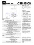
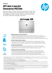
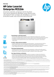
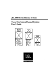
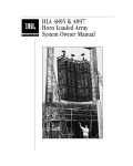
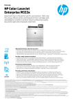
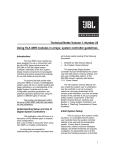
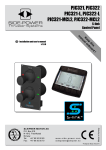
U-Build It Enclosure Guide
UB4755
UB4770
UBSUB
Horizontal Format
Dual 12”+ Compression Driver
system
Vertical Format
Dual 15” + Compression Driver
System
Dual 18”
Add-on Subwoofer
System
Specifications
Specifications
Specifications
Guidelines
Guidelines
Guidelines
Construction Drawings
Construction Drawings
Construction Drawings
Network Schematic
Network Schematic
Components and
Connections
Components and
Connections
Connector Panel Layout
Setting up Your
System
Components and
Connections
JBL Professional Enclosure Guide
1. Introduction
JBL components are known worldwide as the best money can buy. This guide contains construction
details, filter network schematics and connection diagrams for enclosure designs using some of the
most popular of those components, the 2206H, 2226H, 2242H, 2447J and 2404H. These enclosures
are based on popular JBL systems, but have been modified for ease of construction for the intermediate
level woodworker. By following the instructions herein you can build your own system to perform as
well some of JBL’s best designs.
.
1.1. Cabinet construction
Material should be 19 mm, 13 ply void free plywood for general purpose portable applications or high
grade MDF board for less portable applications
Ducts can be made of PVC pipe or hard cardboard tubes such as those found in carpet rolls.
Joints should be glued and screwed. Care should be taken to ensure tight joinery in order to make the
enclosure airtight.
Handles and connector plates must be made airtight. Silicone cement can be used here and in corners
to seal the enclosure.
Interior of box should be lined with damping material, such as fiberglass insulation, to reduce internal
standing waves. Be sure to keep port openings free of material as blockage will decrease their
effectiveness.
Drivers are mounted on the front of the baffle using screws and T-nuts in the baffle. This allows easy
access to interior to adjust damping and easy driver replacement.
1.2 .Construction Tips
Everything is built around the baffle. The baffle rests in dado (groove) in each of the two sides and top
and bottom panels.
Install T-nuts for Drivers and Horns prior to assembly.
The Top and bottoms panels fit OVER the side panels.
Install the back panel LAST. This will allow access to the interior for placement of damping material.
Dry fit all parts before final construction.
INDEX
2. The full range systems : UB4755 and UB4770
2.0. Introduction
The UB4755 and UB4770 are 2-way 12” or 15” woofer and HF compression driver designs with the
option of adding two super tweeters, for 3-way systems. The 12” version is a horizontal format for low
profile single unit use and the 15” is an “arrayable” trapezoidal design for use where multiple units are to
used together to form a larger system.
The components used are as follows :
Table 1.
Name / Description
UB4755
Dual 12” with driver
UB4755
Dual 12” with driver
and tweeters
UB4770
Dual 15” with driver
UB4770
Dual 15” with driver
and tweeters
Components used for UB4755 and UB4770
Configuration
2-way
LF
(2) 2206H
MF
2446J
Horn
2380A
VHF
3-way
(2) 2206H
2446J
2380A
(2) 2404H
2-way
(2) 2226H
2446J
2380A
-
3-way
(2) 2226H
2446J
2380A
(2) 2404H
-
2.1. Connection
Two 8-pin Neutrik Speakon connectors are specified so that you may loop through to another cabinet
(note that that will get you a 2 ohm load) or a subwoofer. DO NOT CONNECT MORE THAN TWO
CABINETS IN PARALLEL. Do not use series wiring.
Table 2
Pin #s
+4,-4
+3,-3
+2,-2
+1,-1
Passive
Use
not used
not used
full range
not used or loop through
for subwoofer
Connector Pin Assignments
Active
Use
VHF (2x2404H Super tweeters, optional)
HF, 2446J compression driver
LF, 2x2206H or 2x2226H
not used or loop through for subwoofer
2.2 Amplifiers
The following amplifiers should be used :
INDEX
Table 3 Amplifiers for each Passband
Pin #s
+4,-4
Passive
Amplifier
unused
+3,-3
unused
+2,-2
JBL MPX1200, 1200W per channel at
4 ohms
unused
+1,-1
Active
Amplifier
JBL MPA275, 275W per channel at 4
ohms (optional)
JBL MPX600, 600W per channel at 4
ohms
JBL MPX1200, 1200W per channel at
4 ohms
unused
The amplifiers should be driven clean, that is, without clipping. At the most, clip lights should just turn on
during occasional programme peaks.
Note : In two-way active mode, you may use an MPA1100 amplifier for the low frequency and make use
of the IM-10 input crossover module. See the crossover section below.
2.3. Crossover
For the passive version, a passive crossover is built-in. For the active versions, a JBL M552 or M553
should be used. The table below details what x-over model, how many units will be needed for a stereo
system and what crossover frequencies should be used. Note that you should assign 2380 series horn
EQ to the 2446J MF compression driver. Make sure that :
a) it is set for 2380 equalization
b) It is assigned to the outputs that will drive the compression driver.
The manual for the M552 or M553 contains specific information on how to make the proper settings.
An alternative to using an external crossover in two way active mode with the UB4755 or UB4770 is to
use an IM-10 input crossover module and an MPA1100 amplifier for the low frequencies, instead of an
M552 and an MPX1200 amplifier. This will provide a more compact system that cannot be modified
externally and therefore provides protection against unauthorized alteration. Horn equalization for the
2380 series of horns is also provided in the module and should be engaged.
Table 4 Optimum Crossover Frequencies and Equipment Options
Name
Description
Configuration
UB4755
or
UB4770
UB4755
or
UB4770
Dual 12/15”
with driver
2-way active
Dual 12/15”
with driver
2-way active
UB4755
or
UB4770
Dual 12/15”
with driver and
tweeters
3-way active
X-over model
/ mode
M552 / stereo
2-way mode
Number
(stereo)
1
IM-10 input
module for
MPA1100
amplifier
M553 / stereo
3-way mode
1
1
X-over
frequencies
1200 Hz,
engage 2380 EQ
for MF
1200 Hz,
engage 2380 EQ
for MF
1200 Hz, 7k Hz,
engage 2380 EQ
for MF
INDEX
Note that you will need to balance the output for each of the frequency bands in relation to the others.
3. The Subwoofer system : UBSUB
3.0. Introduction
The UBSUB is a dual 18” system that utilizes the highest output 18” cone bass transducer currently
available from any manufacturer, the 2242H. The 2242H is designed for smaller enclosures and to
provide a more “punchy” or “faster” low frequency response required for live sound and dance club PA
applications.
3.1. Connection
Two 8-pin Neutrik Speakon connectors are specified so that you may loop through to full range cabinets
or another subwoofers (note that that will get you a 2 ohm load). DO NOT CONNECT MORE THAN
ONE CABINET TO THE AMPLIFIER. Do not use series wiring.
Table 5 Connector Pin Assigments for UBSUB
Pin #s
+4,-4
+3,-3
+2,-2
+1,-1
Active
Use
not used or loop through for full range cabinets
not used or loop through for full range cabinets
not used or loop through for full range cabinets
Subwoofer, 2x2242H
Note: 4-pin Neutrik Speakon connectors can also be used provided that you will be using the full range
systems in passive mode. In that case keep the pin number the same (+2,-2) and use (+1,-1) for looping
through to the subwoofer if you have it.
3.2. Amplifiers
The following amplifiers should be used :
Table 6 Amplifiers for UBSUB
Pin #s
+4,-4
+3,-3
+2,-2
+1,-1
Active
Amplifier
unused
unused
unused
JBL MPX1200, 2400W in bridge mode at 4 ohms
Note that the amplifier is used in bridge mode, so that only one dual 18” cabinet maybe connected to
one amplifier. Using the MPX1200 in bridge mode also means it has more input gain, so you should turn
the subwoofer output down to compensate.
INDEX
The amplifier should be driven clean, that is, without clipping. At the most, clip lights should just turn on
during occasional programme peaks.
3.3. Crossover
The subwoofer system does not have a passive crossover and NEEDS AN ACTIVE crossover. Do not
wire it in parallel with a full-range system as this only rob power from both resulting in poor sound
quality.
JBL cross over models M552 or M553 should be used. The table below details what x-over model, how
many units will be needed for a stereo system and what crossover frequencies should be used. Note
that you should assign 2380 series horn EQ to the 2446J MF compression driver. Make sure that :
a) it is set for 2380 equalization
b) It is assigned to the outputs that will drive the compression driver.
The manual for the M552 or M553 contains specific information on how to perform make the settings.
Table 7 Optimum Crossover Frequencies and Equipment Options
Description
Configuration
X-over model
/ mode
M552 / stereo 2way mode
X-over frequencies
UBSUB subwoofer +
UB4755/4770 in
passive version
UBSUB subwoofer +
UB4755/4770 with
tweeters in passive
version
UBSUB subwoofer +
UB4755/4770 in
active version
UBSUB subwoofer +
UB4755/4770 with
tweeters in active
version
2-way active
2-way active
M552 / stereo 2way mode
80-150 Hz
3-way active
M553 / stereo 3way mode
80-150 Hz, 1200 Hz, engage
2380 EQ for MF
4-way active
M553 / mono 4way mode
(2 units needed)
80-150 Hz, 1200 Hz, 7k Hz,
engage 2380 EQ for MF
80-150 Hz
Note that you will need to balance the output for each of the frequency bands in relation to the others.
If your system allows it, is always good practice to introduce a high pass filter (sometimes referred as a
subsonic filter) beyond the lowest frequency of operation. This will improve power handling by avoiding
excessive cone excursion and will maximize system headroom. For a 4755 or 4770 use a high pass
filter at 40 Hz. When using a 4755 or 4770 in conjunction with the UBSUB subwoofer, cut the subwoofer
signal at 30 Hz (On the MPX series of amplifiers you can accomplish this by engaging the 30 Hz filter on
the front of the amplifier).
Additionally, you may want to replace the M553 or M552 for the JBL DSC260 3-way stereo/6-way mono
digital system controller that will provide programmable cross over, EQ, limiting and time alignment or
delay.
INDEX
4. Setting Up
Before setting up the system interconnection cables should be assembled. It is essential that all cabling
use the proper type and size of wire and that termination is done correctly. This will give the best
performance from the system by eliminating losses from poor or incorrect connection.
4.1 Polarity
One of the most important considerations in cables is that they are in correct polarity. “In polarity” refers
to all signals moving in the same direction at the same time. Having cables improperly connected “out
of polarity” can cause cancellations at certain frequencies thereby adversely affecting frequency
response especially at low frequencies. This translates simply into making certain the “+” and “-”
connections are consistent throughout the system. JBL speaker systems exhibit outward (“positive”)
cone motion when a positive voltage is presented to the “+” terminal.
JBL electronics follow the Pin 2 “Hot” convention for wiring of XLR connectors.
4.1 Speaker Cable
Use the correct thickness for the impedance you will be driving and length of cable you will be running.
Longer runs require thicker cable. Lower impedances also require thicker cables. The table below gives
the maximum length of cable to be used for a given speaker load. For the best performance from your
system these tables should be referenced for your choice of speaker cable.
Table 8 Maximum Cable Length (m) for Gauge of Wire and Speaker Impedance
Gauge
10
12
14
16
18
20
Area mm2
5.26
3.31
2.08
1.31
.82
.52
2 Ohm
18
11
8
5
3
2
4 Ohm
36
23
15
9
6
4
8 ohm
72
45
30
18
12
8
16 ohm
144
90
60
36
24
16
4.2 Taking it further
For optimal fine tuning of your system we suggest the JBL SMAART PRO Software. SMAART PRO is
a full function FFT( Fast Fourier Transform) measurement tool which allows the user to readily see
where frequency response may need adjusting. The software can be used during a performance and
only requires a PC, microphone, and mixer.
INDEX
Figure 1 Network Schematics
INDEX
!
! "
Figure 2 Suggested Connector Panel Layouts
INDEX
UB4755 Performance Specifications
LF Components
2206H (2)
HF Components
2446J w/ 2380A
Sensitivity
198 dB SPL
Power Handling
1200 W LF, 150 W HF
Max Peak SPL
135 dB
Frequency Response
55 - 18k Hz
INDEX
Top & Bottom
Sides
Baffle
Compresion Driver
Support
*Note:
Dimensions are shown as: mm (inches)
All dimensions are based on metric measurements.
Some dimensions may need slight adjustment if
measured in inches.
Duct Tubes
Title: UB4755 Rev. #: 2.3
Drawn by: J. Byron Bishop
JBL Professional
Back
INDEX
&'(
)&*&
+ *,
*&-*&
*,
!"
#
! $% )&*&
&'(
+ *,
#
! $% &'(
+ *,
)&*&
!"#
$!"%&
#
'
&!' ()
" #$ %
. / 0 ! 1 2 #
3 04 !2 5+ * 674
!!
!"#
$!"%&
#
&!' ()
INDEX
UB4770 Performance Specifications
LF Components
2226H (2)
HF Components
2446J w/ 2380A
Sensitivity
100 dB SPL
Power Handling
1200 W LF, 150 W HF
Max Peak SPL
137 dB
Frequency Response
40 - 18k Hz
INDEX
Title: UB4770 Rev. #: 2.3
Drawn by: J. Byron Bishop
JBL Professional
*Note:
Dimensions are shown as: mm (inches)
All dimensions are based on metric measurements.
Some dimensions may need slight adjustment if
measured in inches.
INDEX
&'(
)&*&
+ *,
*&-*&
*,
!"
#
! $% )&*&
&'(
+ *,
#
! $% &'(
+ *,
" #$ %
. / 0 ! 1 2 #
3 04 !2 5+ * 674
&!' ()
)&*&
!"#
$!"%&
#
'
!!
!"#
$!"%&
#
&!' ()
INDEX
UBSUB Performance Specifications
LF Components
2242H (2)
Sensitivity
102 dB SPL
Power Handling
1600 W LF
Max Peak SPL
140 dB
Frequency Response
30 - 200 Hz
INDEX
Title: UBSUB Rev. #: 2.3
Drawn by: J. Byron Bishop
JBL Professional
Internal Support
Top & Bottom
Baffle
Sides
Duct Tubes
*Note:
Dimensions are shown as: mm (inches)
All dimensions are based on metric measurements.
Some dimensions may need slight adjustment if
measured in inches.
Back
INDEX
!"# $ !"## $ !"# $ !"## $ !*
!"# %&
$ ' ()
!"## %&
$ '
()
!*
!*
INDEX