1
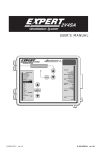
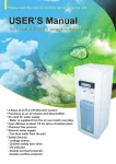
EXPERT 2V4SA
Temperature Controller
User’s manual
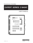
CLEAN MODE
COMPENSATION
HUMIDITY
OUTSIDE TEMPERATURE
CURRENT CONDITIONS
STATIC PRESSURE
STATUS
ROOM TEMPERATURE
LOW TEMPERATURE OVERRIDE
DE-ICING - STAGE 2
PROBE TEMPERATURE
TEMPERATURE CURVE
OUTSIDE TEMPERATURE
MINIMUM SPEED CURVE
RELATIVE HUMIDITY
0-10V CURVE
STATIC PRESSURE
ALARMS
TIME / DATE
DEFECTIVE PROBE
TEMPERATURE ALARM
SETTINGS
WATER ALARM
SET POINT / CURVE
MINIMUM SPEED / CURVE
0-10V OUTPUT
STAGE 1
INLET
OPEN
CLOSE
STAGE 2
MANUAL MODE
STAGES 3-6
RESET
MIST / SOAK
MIST / SOAK
HEATERS
FAN STAGES
INLET
6
0-10V OUTPUT / CURVE
5
ALARMS
4
ALARMS
MONITORING
3
2
WATER HISTORY
1
LAST 48-HOUR WATER
HEATERS
HEATER RUN TIME
CLEAN MODE
USER
TEST
SETUP
1
2
HEAT MAT
EXPERT 2V4SA
WARNINGS
The warranty can be void if this product is used in a manner
not specified by the manufacturer.
Every effort has been made to ensure that this manual is
complete, accurate and up-to-date. The information contained in it is however subject to change without notice
due to further developments.
2
EXPERT 2V4SA, rev.07
EXPERT 2V4SA
TABLE OF CONTENTS
7.
1.INTRODUCTION.............................. 4
1.1.Precautions.................................... 4
1.2. Symbols of the Manual....................... 4
1.3.Features........................................ 5
8.SOAKING..................................... 32
2. MOUNTING INSTRUCTIONS............. 7
2.1. Installing the Controller on the Wall... 7
2.2.Connections................................... 7
2.2.1. Sensor Inputs................................... 7
2.2.2. Alarm Connection............................. 7
3. USER INTERFACE........................... 8
3.1. Location of the Controls.................. 8
3.2. Parameter Adjustment..................... 8
4.
4.1.
4.2.
4.3.
4.4.
4.5.
4.6.
INSTALLATION SETUP.................. 10
Time and Date.............................. 10
Setting the Day Number................. 10
Selecting Type of Motor................ 10
User Setup Menu.......................... 11
Clean Mode.................................. 16
Test Mode................................... 17
5. TEMPERATURE SET POINTS.......... 18
5.1. Set Point Settings......................... 18
5.2. Set Point Curve............................ 18
6.COOLING..................................... 20
6.1. Minimum Ventilation..................... 20
6.1.1.
6.1.2.
6.1.3.
6.1.4.
Principle of Operation...................... 20
Timer Settings................................ 20
Stage 2 in Min Ventilation................ 21
Min Ventilation Curve...................... 22
6.2. Fan Stages................................... 23
6.2.1.
6.2.2.
6.2.3.
6.2.4.
Principle of Operation...................... 23
Fan Stage Start Temperature............ 24
Minimum Fan Speed........................ 24
Adjusting # of Degrees to Reach 100%
of Stages 1 & 2 ............................. 24
6.3. Outside Temperature Compensation ...
25
6.3.1. Compensation on Stage 1 Min Speed.25
6.3.2. Compensation on the Number of Degrees to Reach Full Speed of Stages 1
& 2............................................... 25
9.
MIST COOLING............................ 31
RH COMPENSATION..................... 33
10.HEATERS..................................... 34
10.1.Regular Heating Stages.................. 34
10.2.Zoned Heating.............................. 34
10.3.Heating Timers............................. 34
10.4.Heater Settings............................. 35
10.5.0-10V Heater............................... 35
10.6.0-10V Heat Mat........................... 37
10.7.0-10V Heating Curve..................... 38
11. AIR INLET & CHIMNEY DAMPERS.. 39
11.1.Principle of Operation.................... 39
11.2.Inlet & Chimney Settings............... 40
11.2.1. Actuator Reset............................... 41
11.2.2. Manual Opening of the Actuators..... 43
11.3.Static Pressure Compensation on the
Inlet44
12. MONITORING FUNCTIONS............. 46
12.1.Alarms........................................ 46
12.1.1. Managing the Alarms...................... 46
12.1.2. Alarm Conditions............................ 47
12.1.3. Alarm Settings............................... 48
12.2.Water Consumption...................... 49
12.2.1.History.......................................... 49
12.2.2. Water Consumption of the Last 48
Hours............................................ 49
12.3.Heater Run Time History................ 50
13. CURRENT CONDITIONS................. 50
13.1.Current Room Temperature............ 50
13.2.Probe Temperatures...................... 51
13.3.Outside Temperature..................... 51
13.4.Current Humidity Level.................. 52
13.5.Current Pressure Level................... 52
13.6.Current Speed of the Variable Fans. 52
14. TECHNICAL SPECIFICATIONS........ 53
15. MEMORY CARD........................... 54
16. INSTALLATION REPORT................ 55
6.4. Merging Fan Stages...................... 27
6.4.1. Merging Fan Stages 1 & 2............... 27
6.4.2. Merging Stages 2 and 3.................. 27
6.4.3. Nbr of Degrees to 100% of Stage 3.. 28
6.5. De-icing Stage 2 Fans.................... 28
6.6. 0-10V Fan Output......................... 29
EXPERT 2V4SA, rev. 07
3
EXPERT 2V4SA
1.
INTRODUCTION
1.1.
Precautions
1.2.
Warning. Read the following text
carefully; it contains important
information which, if ignored, may
cause the controller to operate
improperly.
WARNING: Read and save these
instructions!
Safety may be jeopardized if the equipment
is used in a manner not specified by the
manufacturer. Carefully read and keep the
following instructions for future reference.
High Voltage. Hazard of electrical
shock. Read the message and follow
the instructions carefully.
We strongly recommend installing supplementary natural ventilation as well as a back-up
thermostat on at least one cooling stage (refer
to the wiring diagram enclosed with this user’s
manual to connect the thermostat).
Pay attention. The following text
contains very useful information.
Both direct and alternating current
(AC/DC).
Although fuses at the input and outputs of
the controller protect its circuits in case of
an overload or over-voltage, we recommend
installing an additional protection device on
the controller’s supply circuit.
Direct current (DC).
Alternating current (AC).
Earth Ground Terminal
Primarily used for functional earth
terminals which are generally associated with test and measurement
circuits. These terminals are not for
safety earthing purposes but provide
an earth reference point.
The room temperature where the controller
is located must always remain between 32°F
and 104°F (0°C to 40°C). Indoor use only!
To avoid exposing the controller to harmful
gases or excessive h
umidity, it is preferable
to install it in a corridor.
If the equipment is used in a manner not
specified by the manufacturer, the protection provided by the equipment may be
impaired.
Do not spray water on the controller! In
order to clean the control, wipe it with a
damp cloth.
Before servicing or cleaning unit,
switch power off at service panel
and lock the switch disconnecting
means to prevent power from being
switched accidentally. When the service disconnecting means cannot be
locked, securely fasten a prominent
warning device, such as a tag, to the
service panel.
4
EXPERT 2V4SA, rev.07
Symbols of the Manual
For Customer Use: Enter below the serial
number located on the side of the alarm
system and keep this information for future
reference.
Model:
EXPERT 2V4SA
Serial number:
Date installed:
EXPERT 2V4SA
1.3.
Features
The EXPERT 2V4SA is an electronic device
used for environmental control in livestock
buildings. It allows the user to maintain a
specified target temperature by controlling
the operation of ventilation and heating
equipment. The EXPERT 2V4SA can control
the following outputs:
- 2 variable fan outputs
- on/off outputs (heaters, misters or fans)
- 1 air inlet output
- 1 0-10V output (heaters, heat mats, chimney or fans)
Main Features :
LCD Display — An LCD display provides an
efficient interface for displaying, monitoring
and adjusting parameter values.
Pilot Lights — Pilot lights indicating the state
of outputs allow the user to monitor the
operation of the system without having to
enter the building.
Removable Connectors — Input connectors
can be removed from the main board to
simplify wiring.
Minimum Ventilation Cycle — When ventilation is not required for reducing room
temperature, the first and second fan stages
can be operated either continuously or intermittently to reduce the level of humidity and
supply oxygen to the room.
Temperature & Min. Ventilation Curves —
The controller can be set to automatically
change the temperature set point and the
minimum ventilation cycle over a given period of time, in accordance with the user's
requirements, by specifying a temperature
curve and a minimum ventilation cycle curve
with up to ten different points each.
Choice of Ten Motor Types — The variation
in motor speed resulting from a change in
voltage will depend on the make and capacity of the motor. In order to achieve a high
degree of compatibility between controller
and motor, the user can choose from among
ten different motor types, thus ensuring that
the correct voltage is supplied.
Zoned Heaters
Probe Readings Recorded For Past Days —
Minimum and maximum readings from temperature probes, static pressure sensors and
humidity sensor are recorded for the current
day and the p
revious six days.
Water Monitoring — A pulse input is provided
for monitoring water consumption for the current days and the previous six days.
Heater Run Time Monitoring — Heater run
times are kept in memory for the current day
and for the p
revious six days.
Alarm Management — Alarms are provided
for high-low temperatures, defective probes
and other system functions.
Four Temperature Probe Inputs — Up to four
temperature probes can be connected to the
controller in order to obtain a more accurate
reading of the average room temperature and
a faster reaction time.
Outside Temperature Compensation — Fan
stages are automatically adjusted according
to the outside temperature. This ensures a
better stability in the room temperature.
0-10V Output — One 0-10V output can be
activated to control supplementary ventilation or heating stages or to control chimney
dampers.
EXPERT 2V4SA, rev. 07
5
EXPERT 2V4SA
Humidity Compensation — The control offers
many ways to compensate for high or low
humidity levels.
Static Pressure Control — A static pressure
input is provided to control the static pressure
level by opening and closing the air inlets.
When the pressure level is too high, the inlet
opens to compensate. When the pressure
level is too low, the air inlet closes.
Control of Air Inlet Movement — The movement of air inlet can be coordinated with the
operation of the fans. This allows the air inlet
to be adjusted correctly, without the influence of uncontrollable factors such as wind
or air from adjoining rooms.
Password Protection — A password allows
to restrict access to the controller's setup
functions.
Backup Battery — A backup battery allows
the unit to keep time in case of a power
failure.
Overload And Overvoltage Protection — Resettable fuses are provided at low-voltage
inputs and outputs of the controller to protect its circuitry in the case of an overload
or overvoltage.
Computer Control — The controller can be
connected to a computer, thus making it
possible to centralize the management of
information and diversify control strategies.
Test Mode — A test mode allows you to
simulate temperature changes and verify
controller's performance.
6
EXPERT 2V4SA, rev.07
EXPERT 2V4SA
2.
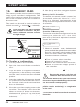
2.1.
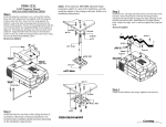
MOUNTING INSTRUCTIONS
Installing the Controller on
the Wall
Open the latch and lift the cover. Remove
the black caps located on each of the four
mounting holes. Mount the enclosure on
the wall using four screws. Be sure the
electrical knockouts are at the bottom of
the enclosure in order to prevent water from
entering the controller. Insert the screws in
the mounting holes and tighten. Fasten the
four black caps provided with the controller
onto the four mounting holes. The enclosure
must be mounted in a location that will allow
the cover to be completely opened right up
against the wall.
2.2.
Connections
Refer to the wiring diagram enclosed with this
user’s manual to connect the controller. Drill
holes at the bottom of the enclosure to pass
the wires and install watertight connectors to
prevent water from entering in the enclosure.
Do not make any holes at the side and top
of the enclosure.
All wiring must be done by an authorized electrician and must comply
with applicable codes, laws and
regulations. Make sure power is off
before doing any wiring to avoid
electrical shocks and equipment
damage.
Note that the input terminal blocks
can be removed from the electronic
board. This makes it easier to make
the connections.
2.2.1. Sensor Inputs
Sensors operate at low voltage and are isolated
from the supply. Make sure that sensor cables
remain isolated from all high voltage sources.
In particular, do not route the sensor cables
through the same electrical knockout as other
cables. Do not connect the shield from the
sensor cable to a terminal or a ground.
Extending a sensor: Each sensor can be extended up to 500 feet (150 meters).
To extend a sensor: Use a shielded cable
of outside diameter between 0.245 and
0.260 in (6.22 and 6.60 mm) (the cable
dimensions should not be under 18 AWG) to
ensure the cable entry is liquid tight. Do not
ground the shielding.
It is preferable to solder the cable joint to
ensure a proper contact between the two
cables.
Do not run sensor cables next to other
power cables. When crossing over
other cables, cross at 90°.
Defective sensors:
A n alarm is gener1: 74.2 2:----ated when a defective
3: 72.3 4:73.0
sensor is detected.
To identify the defective probe, select the
PROBE TEMPERATURE or OUTSIDE TEMPERATURE menu. Probe readings are then
displayed. Dashes are displayed instead of a
reading when the probe is defective. In the
case of room temperature probes, the controller will operate according to the temperature
of the remaining probes.
2.2.2. Alarm Connection
There are two types of alarms on the market.
One type activates when current is cut off at
its input, whereas the other activates when
current is supplied at its input. For an alarm of
the first type, use the NC terminal as shown on
the wiring diagram. For an alarm of the second
type, use the NO terminal.
EXPERT 2V4SA, rev. 07
7
EXPERT 2V4SA
3.
USER INTERFACE
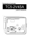
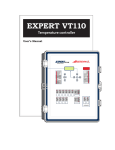
3.1.
Location of the Controls
Digital
Display
LED Display
CLEAN MODE
COMPENSATION
HUMIDITY
OUTSIDE TEMPERATURE
CURRENT CONDITIONS
Main menu
STATIC PRESSURE
STATUS
ROOM TEMPERATURE
DE-ICING - STAGE 2
PROBE TEMPERATURE
TEMPERATURE CURVE
OUTSIDE TEMPERATURE
MINIMUM SPEED CURVE
RELATIVE HUMIDITY
0-10V CURVE
STATIC PRESSURE
ALARMS
TIME / DATE
WATER ALARM
SET POINT / CURVE
MINIMUM SPEED / CURVE
0-10V OUTPUT
STAGE 1
INLET
Menu
selectors
STAGE 2
STAGES 3-6
MIST / SOAK
HEATERS
Navigation &
Adjustment
keys
OPEN
CLOSE
MANUAL MODE
RESET
MIST / SOAK
FAN STAGES
INLET
6
0-10V OUTPUT / CURVE
5
ALARMS
4
Digital LED Display
play at the top can
of information such
temperature, static
position, etc.
— The red LED disshow various pieces
as the average room
pressure level, inlet
LAST 48-HOUR WATER
HEATER RUN TIME
CLEAN MODE
USER
TEST
3
MONITORING
ALARMS
SETUP
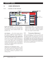
LCD Display — The LCD screen shows
the current readings and parameters to
be adjusted when you select a function.
The three keys next to the display are
used to edit parameters and scroll down
the menus. When the parameters for a
given function cannot all be presented at
once on the display, arrows are displayed
on the right hand side to indicate that
additional parameters can be displayed
using the arrow keys. After 15 minutes of
inactivity, the display returns to the current
temperature display.
Adjustment and Navigation Keys — The
arrow keys on top are used to scroll down
the menus when the parameters cannot
be presented all at once. These keys are
also used to modify a parameter in the
editing mode.
8
DEFECTIVE PROBE
TEMPERATURE ALARM
SETTINGS
WATER HISTORY
Output
status LEDs
LOW TEMPERATURE OVERRIDE
EXPERT 2V4SA, rev.07
2
Output Status LEDs — The LEDs located
at the left side of the control panel give the
status of each output. When an output
LED is on, the output is activated; when it
is off, the output is deactivated.
1
HEATERS
1
2
HEAT MAT
3.2.
Parameter Adjustment
Select a parameter you want to adjust and
then press the MODIFY push-button to enter
the editing mode. The parameter's value will
start flashing on screen which means it can
be modified. Use the up and down-arrow
keys located next to the display to modify the
parameter's value. Finally, press the MODIFY
push-button to validate the new value and to
exit from the editing mode.
EXPERT 2V4SA
LED
MEANING
Clean Mode
Solid LED:
Clean mode is active.
Humidity Compensation
Solid LED
A RH compensation function is ON.
Outside Temp. Compensation
Solid LED
The outside temperature compensation is ON.
Static Pressure Compensation
Solid LED
A static pressure compensation is applied on the inlet
opening.
Low Temperature Override
Solid LED
The low temperature override parameters are ON.
De-icing Stage 2
Solid LED
Stage 2 fans are being de-iced.
Temperature Curve
Solid LED
The temperature set point is defined by a curve.
Minimum Speed Curve
Solid LED
The minimum ventilation speed is defined by a curve.
0-10V Curve
Solid LED
The start T° of the 0-10V output is defined by a curve.
Defective probe alarm
Solid LED
A defective probe alarm is active.
Flashing LED
A defective probe alarm occurred, no longer exists,
and must be acknowledged.
Solid LED
A temperature alarm is active.
Flashing LED
A temperature alarm occurred, no longer exists, and
must be acknowledged.
Solid LED
A water spill or water consumption alarm is active.
Flashing LED
A water spill or water consumption alarm occurred, no
longer exists, and must be acknowledged.
0-10V output
Solid LED
The 0-10V output is active.
Inlet
Open
Solid LED
The air inlet is opening.
Close
Solid LED
The air inlet is closing.
Manual Mode
Solid LED
The inlet operates in manual mode.
Reset
Flashing LED
The controller is now opening or closing the air inlet in
order to reset the actuator’s position.
Solid LED
Time On of the mist or soaking timer.
Flashing LED
Time Off of the mist or soaking timer.
Fan stages 1-6
Solid LED
The fan stage is ON.
Heaters 1-2
Solid LED
The heating stage is ON.
Heat mat
Solid LED
The heat mat is ON.
Temperature alarm
Water alarm
Mist/ Soak
EXPERT 2V4SA, rev. 07
9
EXPERT 2V4SA
4.
INSTALLATION SETUP
4.1.
Time and Date
4.3.
Selecting Type of Motor
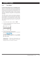
3. Use the adjustment keys to set the first
parameter flashing on screen.
The relationship between the voltage supplied
to a motor and its operating speed is described
by a motor curve. This curve varies with the
make and capacity of the motor. The various
motors available in the industry have been
divided into ten categories and the controller
has been programmed with a different motor
curve for each of these categories. To ensure
that the controller supplies the correct voltages, an appropriate curve must be selected
for Stage 1 and Stage 2, according to the type
of fan motors used.
4. Press MODIFY to step to the next parameter.
1. From the main menu, select: STAGE 1 or
STAGE 2.
5. Proceed the same way to set the whole
time and date.
2. Press the down-arrow key to select this
screen:
1. From the main menu, select: TIME &
DATE.
12:00:00 PM
01/01/200X
2. Press MODIFY to enter the editing mode.
4.2.
Setting the Day Number
The day number refers to the day that is currently being used by the controller’s curves
and usually corresponds to animal age. The
day number can be modified in order to move
forward or backward on the curves.
Making a change to the day number
will affect all curves in use (Min.Vent,
Set Point & 0-10V Heat curves).
1. From the main menu, select: SET POINT
/ CURVE.
2. Use the navigation keys to select this
screen:
Current day
9
*This screen is accessible if a curve function
and/or a 0-10V heating output is enabled in the
“User Setup Menu” on page 11.
3. Select the desired day number.
(The parameter adjustment process is explained
in section 3.2 on page 8).
10
EXPERT 2V4SA, rev.07
Motor curve
4
3. Set the following parameters:
(The parameter adjustment process is explained
in section 3.2 on page 8).
Motor Curve — Set the motor curve of the
selected fan stage to the desired value.
EXPERT 2V4SA
4.4.
User Setup Menu
The following section shows how to customize the controller for your particular application. Normally, this setup needs to be done
only once at controller startup. A template
is available at the end of this manual to write
down your particular parameter settings.
Before you begin, be sure to know what will
be assigned to each stage of the controller.
The table below gives all possible stage
combinations.
Settings:
1. From the main menu, select: USER.
2. Set the following parameters:
(The parameter adjustment process is explained
in section 3.2 on page 8).
Contrast — Set the contrast of the LCD
screen to the desired value (from 10 to
100%).
Contrast:
80
Time Format — Select the desired time
format: AM-PM or 24-hour.
Time format
AM-PM
Temperature Units — Select the temperature units: Fahrenheit (F°) or Celsius (°C)
degrees.
Temp. units
°F
# of Temperature Sensors in the Room —
Set the number of temperature sensors
that are connected to the controller (1-4).
#T° sensors in
the room:
4
Room Probes — Select which of the room
sensors are used to be part of the average
room temperature. Blinking digits represent probes that are selected to be part
of the average room temperature. At least
one temperature probe must be selected.
Press MODIFY then use the arrow keys to
set the status of each probe.
Room probes
1234
Use Water Meter — Select "Yes" if a water
meter is connected to the controller.
Use water meter?
No
Water Meter Units — Select the water
units: Gallons or liters. *This parameter is
accessible if the water meter is enabled above.
Water meter unit
lit
Water Meter Calibration —Set the number of gallons or liters per pulse. *This
parameter is accessible if the water meter is
enabled above.
Water unit/pulse
1
Use Humidity Sensor— Select "Yes" if a
relative humidity sensor is connected to
the controller.
Use humidity
sensor?
No
Humidity Compensation on Min. Speed
— Select "Yes" to enable the compensation of stage 1 fan speed, according to
the humidity level (see chapter 9 on page
33).*Accessible if the humidit y s ensor is
enabled above.
Rh influence on
Min. Speed?
No
Use Outside Temperature Sensor — Select
"Yes" if an outside temperature sensor is
connected to the controller.
Use Out T°
sensor?
Yes
Outside T° Compensation on Min. Speed—
Select "Yes" to activate the outside temperature compensation on the minimum
speed of stage 1 fans (see section 6.3 on
page 25). *This parameter is accessible if
EXPERT 2V4SA, rev. 07
11
EXPERT 2V4SA
the outside temperature sensor is enabled above.
Out T° compens.
Min Speed?
No
on page 11). Up to two heater stages
can be used. Then, set the number of 0-10V
output (0-1 output).
#Heaters:
#0-10V
Use Outside Temperature Compensation
on Stages 1 & 2 — Select "Yes" to activate the outside temperature compensation on the number of degrees required
to reach 100% of fan stage 1 and 2 (see
section 6.3). **This parameter is accessible if
the outside temperature sensor is enabled above.
Out T° compens.
stage1?
Out T° compens.
stage2?
Winter& Summer Reference T° — Set the
temperature that signals the b
eginning of
winter and summer. *This parameter is accessible if the outside compensation function is
enabled above.
Outside T° in
winter:
41.0°F
Outside T° in
summer:
59.0°F
Use the Static Pressure Sensor — Select
"Yes" if a static pressure sensor is connected to the controller.
Use Stat. P
sensor?
Yes
Use the Static Pressure Compensation —
Select "Yes" to use inlets to compensate
for high or low pressure levels (see section 11.3 on page 44). *This parameter
is accessible if the static pressure sensor and
inlet are enabled.
Use Stat. P
compens.?
No
Heaters and 0-10V Outputs — Enable the
desired number of heating stages (refer to
the stage combination table in section 4.4
12
EXPERT 2V4SA, rev.07
1
1
0-10V Output Used for — Select the
operating mode of the 0-10V output:
Ventilation / Heating / Chimney damper /
Heat mat. *This parameter is accessible if the
0-10V output is enabled above.
0-10V used for
Ventilation
0-10V follows the Set Point ? — Select
“Yes” if the start temperature of the
0-10V output is related to the set point.
This means that when the set point
changes, the start temperature is adjusted
by the same amount. Select “No” to use an
absolute start temperature for this output.
*This parameter is accessible if the 0-10V output
is enabled above.
0-10V follows
setpoint?
No
Use 0-10V Curve — If the 0-10V is used for
heating, it is possible to define a 10-point
curve to change its start temperature of
over time. Select “Yes” to enable this function or “No” to disable it. *This parameter
is accessible if the 0-10V output function is set
to “Heating” or to “Heat mat” above and if the
output does not follow the Set Point.
EXPERT 2V4SA
Output Mode (0-10V or 10-0V) — Select
the type of signal used by the 0-10V output (0-10V or 10-0V). *This parameter is
accessible if the 0-10V output is enabled above.
0-10V Mode
0-10V
Use Soaking — Select “Yes” to enable the
soaking function.
Use Soaking ?
Yes
Use Mist — Select "Yes" to enable the
mist function.
Use Inlet — Select “Yes” to enable the
air inlet.
Use Overopening — A supplementary
stage can be defined in order to continue
opening air inlet beyond the activation
temperature of the last ventilation stage.
This over-opening stage is used to direct
the airflow more efficiently during periods
of warm weather. Select “Yes” to enable
the inlet over-opening function or select
“No” to disable it. *This parameter is accessible if an air inlet is enable above.
Use Overopening Yes
Move in 1 Step — The air inlet can either
reach its over-opening position instantaneously when the room temperature
reaches a certain point or it can reach its
over-opening position gradually as the
room temperature departs from the start
temperature of the last fan stage. Select
“Yes” to use the instant opening mode
or select “No” to use the progressive
opening mode. Note that either case, the
inlet reaches its full over-opening position
at: On T° of the last fan stage + OverOpening bandwidth (see chapter 11). *This
parameter is accessible if the over-opening function is enabled above.
Move in 1 step?
No
Use a timer on heating stages — Select
"Yes" for heater to run in timer mode as
a function of the room temperature. *This
parameter is accessible if at least one heating
stage is enabled above.
Use heaters on
timer ?
No
Zoned or standard heaters — Zoned
heating allows heating stages to operate
according to specific temperature sensors instead of using the average room
temperature as a reference. *This parameter
is accessible if two heating stages are enabled
above.
Use Zoned heater?
No
Heater 1-2 probes — Select which probes
are used to control each heating stage.
Blinking digits represent probes that are
assigned for this purpose. At least one
temperature probe must be selected. Press
MODIFY then set each probe's status with
the arrow keys. *This parameter is accessible
if zoned heaters are enabled above.
Heater 1 probes
1234
Heater 2 probes
1234
Merge between stages 1 and 2 — Select
"Yes" if to enable the merge between fan
stages 1&2 (see “Merging Fan Stages” on
page 27).
Use merge for
stages 1-2
No
Merge between stages 2 and 3 — Select
"Yes" to enable the merge between fan
stages 2 and 3 (see “Merging Fan Stages”
on page 27). *This parameter is accessible
if stage 3 is used as a fan stage (refer to the stage
combination table in section 4.4).
Use merge for
stages 2-3
No
EXPERT 2V4SA, rev. 07
13
EXPERT 2V4SA
De-icing Stage 2 — Select "Yes" if to enable the de-icing feature on fan stage 2.
Use de-icing on
stage 2?
No
Use Night Set Point — Select "Yes" to use
a night set point.
Use night setp?
Yes
Night Set Point Starts at — Select the time
at which the night set point starts being
used. *This parameter is accessible if the night
set point is enabled above.
Night setp at
8:00P
Day Set Point Starts at — Select the time
at which the day set point starts being
used by the controller. *This parameter is
accessible if the night set point is enabled above.
Day setp at:
7:30A
Transition Time — Set the transition time
between day and night set points to the
desired value. It can be adjusted from 15
to 120 minutes. *This parameter is accessible
if the night set point is enabled above.
Transition time
60 min
Low Temperature Override — Select "Yes"
to enable the low temperature override
functions: A) decrease the speed of stage
1 fans & stop stage 2 fans. B)Close the
air inlet further).
Low T° override
Yes
Override Below — Set the temperature
below which "Low temperature override"
options starts. This temperature is directly
related to the set point which means it is
automatically adjusted as the set point
changes and it ranges from 1°F to 40°F
(0.6 to 22.2°C) below the set point. *This
14
EXPERT 2V4SA, rev.07
parameter is accessible if the "Low temperature
override" feature is enabled above.
Override below
70.0°F
Override Stops at — Set the temperature
above which override functions stop.
This temperature is directly related to the
set point which means it is automatically
adjusted as the set point changes. *This
parameter is accessible if the "Low temperature
override" feature is enabled above.
Override stop at
75.0°F
Low Temperature Override Settings — Set
the minimum speed of stage 1 fans and the
inlet position that is reached when the "Low
Temperature override" function is enabled.
*This parameter is accessible if the "Low temperature override" feature is enabled above.
Min spd
Inlet
15%
0%
Set point curve? — Select "Yes" to enable
the set point curve function.
Set point curve?
Yes
Min speed curve — Select "Yes" to enable
the minimum speed curve function.
Min speed curve?
Yes
Display — Select the desired LED display
amongst the following options:
- Temperature only (T° Only);
- Alternating display between temperature
and the static pressure (T° & SP);
- Alternating display between temperature
and the inlet position (T° & Inlet);
- Alternating display between temperature,
inlet position and static pressure (T° &
SP & Inlet).
EXPERT 2V4SA
Display:
T° & Inlet
Change Password — The user can define
a password to restrict access to certain
functions (USER SETUP and TEST MODE).
The password must be entered each time
one of these functions is selected. When
the correct password is entered, it does
not need to be reentered until the display
times out (i.e. after 15 minutes of inactivity). The password is a sequence of three
numbers from 0 to 99. To disable it, set
the password to 0, 0, 0. By default, the
password is disabled. *Use the MODIFY
button to step from a digit to the next.
New password?
00 ** **
Program Version Number — The version
number of the controller is displayed.
EXPERT 2V4SA
Version X.X
EXPERT 2V4SA, rev. 07
15
EXPERT 2V4SA
4.5.
Clean Mode
The clean mode is used to interrupt regular
operations of the controller when the room
is empty. When this mode is enabled, the
controller only provides a minimum level of
heat and ventilation (optional). If minimum
ventilation is used in the clean mode, the
air inlet will open to its respective minimum
ventilation position; otherwise it will remain
closed.
Cleaning the room: A soaking output can be
used to clean up the room. If this output is
enabled, it will automatically start running
according to a user-defined timer at clean
mode startup. Refer to chapter 8 on page
32 to get further information about the
soaking output.
Clean mode set point: During the clean mode,
the fans that are used to provide minimum
ventilation and the heaters operate according to the clean mode set point: the heaters
turn on when the room temperature is lower
than the clean mode set point and fans turn
on when temperature is higher than this set
point.
Low temperature alarm: The controller can
sound an alarm if temperature gets too low
while being in clean mode. Refer to section
12.1.3 to set this alarm limit.
1. From the main menu, select: CLEAN
MODE.
Status:
Setp:
End of clean
delay:
15min
Use minimum
vent.?
No
Detect low
temp. ?
No
Off
45.0°F
2. Set the following parameters:
(The parameter adjustment process is explained
in section 3.2 on page 8).
Status — Select “On” to enable the clean
mode or select “Off” to disable it.
Clean mode set point — Select what is
the target room temperature while the
controller operates in clean mode.
End of clean delay — At the end of the
clean mode, the controller waits a certain
time before monitoring temperature alarms
again. Specify the time required for the
room temperature to get back to normal
or select “Off” to disable this function
(decrease the parameter value until letters
“Off” are displayed).
Use minimum ventilation? — Select “Yes”
to activate minimum ventilation cycles
while the clean mode is on.
Detect low temperature? — Select “Yes”
to enable the low temperature alarm
limit or select “No” to disable this alarm
condition.
16
EXPERT 2V4SA, rev.07
EXPERT 2V4SA
4.6.
Test Mode
A test mode allows you to simulate temperature changes and verify controller performance. In test mode, the room temperature
probe inputs are turned off, allowing the user
to change the temperature used by the controller to operate the stages. The controller
operates as before using the new temperature
settings.
The test mode is used to simulate temperature changes in order to verify the controller’s
performance. The temperature probe inputs
are turned off while the test is on and the
test automatically ends after 15 minutes of
inactivity.
1. From the main menu, select: TEST.
2. Use the navigation keys to select the following parameters:
Test Mode
Room T° bypass:
78.0°F
Off
3. Set the following parameters:
(The parameter adjustment process is explained
in section 3.2 on page 8).
Test Mode Status — Select “Yes” to enable
the test mode or select “No” to exit from
the test mode.
Temperature — Enter the simulated room
temperature. *This parameter can only be
changed when the test mode is enabled.
EXPERT 2V4SA, rev. 07
17
EXPERT 2V4SA
5.
TEMPERATURE SET
POINTS
The set point is a target temperature in
the room. The activation of most outputs
of the controller is based on this reference
temperature.
Note that the set point can only be
modified while the set point curve
is disabled. Refer to the following
section to disable the curve.
5.1.
Set Point Settings
1. From the main menu, select: SET POINT
/ CURVE.
2. Set the following parameters:
(The parameter adjustment process is explained
in section 3.2 on page 8).
Setp
ClnSetp
Night Setpoint
75.0°F
75.0°F
45.0°F
Setp — Set the temperature set point
that is used during the day (this set point
is used all day long if the night set point
is not enabled). It ranges from -40.0°F to
100°F (-40.0°C to 37.8°C) *This parameter
can only be modified while the set point curve is
inactive (sec. 5.2.)
Clean mode set point — Select what is
the target room temperature while the
controller operates in clean mode.
Night Set Point — A different temperature
set point can be used at night. The night
set point can be used to lower the target
room temperature for instance. This set
point is relative to the day set point, which
means that it is automatically adjusted
when the day set point changes. Set the
night set point to the desired value. *This
parameter is accessible if the night set point is
enabled in the User Setup Menu.
18
EXPERT 2V4SA, rev.07
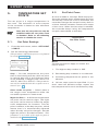
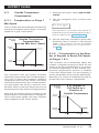
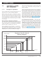
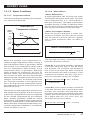
5.2.
Set Point Curve
A curve is made of 10 steps. Each step specifies a day number and a temperature set point
for that day. Once the curve is activated, the
controller changes the set point every hour in
a linear fashion between consecutive steps
of the curve. When the last step is reached,
the controller keeps using the temperature
set point associated to that day.
Temperature
90.0
87.2
84.4
81.6
78.8
76.0
73.2
70.4
67.6
64.8
62.0
1 5
Temperature
Set Point Curve
10
14 19 24 28 33 38 42 47Day
Notes
Certain restrictions apply to reduce the
risk of errors:
1. The highest day number is 365.
2. Decreasing day numbers is not allowed.
3. Increasing temperature set points is not
allowed.
4. All ten steps must be specified. If you
don’t need ten different steps, repeat the
last temperature for each unnecessary step.
EXPERT 2V4SA
Curve Settings
1. From the main menu, select: SET POINT
/ CURVE.
If all curves are disabled (Min.Vent,
Set Point & 0-10V Heat curves), the
controller will automatically set the day
number back to 1 day when a curve
is being activated.
2. Use the navigation keys to select this
screen:
1. day
Setp
1
82.0°F
(This screen is accessible if the set point curve
is enabled in the User Setup Menu).
3. Set the following parameters:
(The parameter adjustment process is explained
in section 3.2 on page 8).
1. day
Setp
1
82.0°F
2. day
Setp
5
78.0°F
...
10. day
40
Setp
62.0°F
Curve status
Off
These parameters can only be modified while the curve is off.
Day numbers — Set the day at which each
curve step starts.
Setp — Assign a temperature set point to
each step of the curve.
Curve status — Select “Yes” to enable
the curve (or "No" to disable it). Once the
curve is on, the controller automatically
adjusts the set point between consecutive
points of the curve; for this reason, curve
steps cannot be modified while the curve
is running.
EXPERT 2V4SA, rev. 07
19
EXPERT 2V4SA
6.
COOLING
6.1.
Minimum Ventilation
Refer to section 6.2.3 to set the
minimum speed of stage 1.
6.1.2. Timer Settings
6.1.1. Principle of Operation
Definition: Minimum ventilation cycles are
activated when the room temperature is
lower than the set point. Running the fans
even though ventilation is not required for
reducing the room temperature is useful to
reduce humidity levels and supply oxygen
to the room. It also prevents the fans from
freezing in winter.
Minimum Ventilation Timer: During the "Time
On", the fans of stage 1 run at their minimum
speed and the status LED associated with
stage 1 is on; during the "Time Off", the fans
return to a stop and the status LED is off.
Note that the minimum speed of stage 1 can
automatically be adjusted with time by using
a curve (see section 6.1.4 on page 22).
Min.Vent
Status
Minimum
Ventilation Timer
ON
OFF
Time On
Time
Off
Time
Hints
The controller supplies maximum
voltage to the variable-speed fans
for 2 seconds at each start-up.
To run the fans continuously at
minimum speed, set the Time Off
to zero and Time On to any value
other than zero.
To stop the fans, set the Time On
to zero and Time Off to any value.
20
EXPERT 2V4SA, rev.07
1. From the main menu, select: STAGE 1.
2. Use the navigation keys to select this
screen:
On:
Off:
30sec
120sec
3. Set the following parameters:
(The parameter adjustment process is explained
in section 3.2 on page 8).
On — Set the “Time On” of the minimum
ventilation timer. This parameter ranges
from 0 to 900 seconds and can be adjusted in increments of 15 seconds.
Off — Set the “Time Off” of the minimum
ventilation timer. This parameter ranges
from 0 to 900 seconds and can be adjusted in increments of 15 seconds.
EXPERT 2V4SA
6.1.3. Stage 2 in Min Ventilation
1. From the main menu, select: STAGE 2.
Stage 2 fans can be used to provide minimum
ventilation as shown on the graph below:
2. Use the navigation keys to select this
screen:
Stage 2 Fans
in Minimum Ventilation
Ventilation
Level
Stage 2
full speed
Stage 2
minimum
speed
0.3°F
Stage 2
Off
Min Ventilation.
On
3. Set the following parameters:
(The parameter adjustment process is explained
in section 3.2 on page 8).
Minimum ventilation — Select "Yes" if to
use stage 2 fans in minimum ventilation.
Stage 1
full speed
Stage 1
minimum
speed
Stage 1
Off
0.3°F
Min.
Vent.
# degrees
to reach full
speed of
stage1
T°SetPoint
Room
# degrees Temp
to reach full
speed of
stage2
Stage 2
Start T°
- When the room temperature falls below the
start temperature of stage 2, stage 2 fans run
intermittently according to the same timer as
the one used by stage 1.
- When the room temperature increases
above the start temperature of stage 2, stage
2 fans start increasing in speed continuously.
Low Temperature Override: If the room temperature gets too cold while the controller
is in minimum ventilation, low temperature
override functions can be enabled to reduce
the speed of stage 1 fans and to stop stage 2.
This allows reheating the room faster. Refer
to the “User Setup Menu” on page 11
to enable the Low Temperature Override
functions.
EXPERT 2V4SA, rev. 07
21
EXPERT 2V4SA
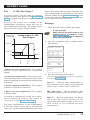
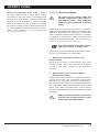
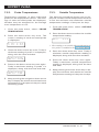
6.1.4. Min Ventilation Curve
Settings:
A curve is made of 10 steps. Each step specifies a day number and a minimum ventilation
speed for that day (the day number refers to
the animal age). When the curve is activated,
the controller changes the minimum ventilation speed every hour in a linear fashion
between consecutive steps of the curve.
When the last step is reached, the controller
keeps using the speed associated to that day.
1. From the main menu, select: MIN. SPEED/
CURVE.
Min Vent.
Speed
10
9
8
7
6
5
4
3
2
1
Min. Ventilation
Curve
1234567810
1112
DAYS
2. Use the navigation keys to select this
screen:
1. The highest possible day number is 365.
2. Decreasing day numbers are not allowed
3. Decreasing min speeds are not allowed.
4. All ten steps must be specified. If you
don’t need 10 different steps, repeat the
last speed for each unnecessary step.
Refer to section 4.2 on page 10
to set the current day number.
1
30%
This screen is accessible if the set point curve is
enabled in the User Setup Menu.
3. Set the following parameters:
(The parameter adjustment process is explained
in section 3.2 on page 8).
Curve status
Off
1. day
Min Spd
1
1. day
Min Spd
5
Notes: Certain restrictions apply to reduce
the risk of errors:
1. day
Min Spd
30%
45%
...
10. day
Min Spd
40
100%
Curve status — Select “Yes” to enable
the curve (or "No" to disable it). Once the
curve is on, the controller automatically
adjusts the set point between consecutive points of the curve; for this reason,
curve steps cannot be modified while the
curve is running.
If all curves are disabled (Min.Vent,
Set Point & 0-10V Heat curves), the
controller will automatically set the day
number back to 1 day when a curve
is being activated.
The parameters below can only be
modified while the curve is off.
Day numbers — Set the day at which each
curve step starts.
Min Spd — Assign a minimum speed to each
step of the curve.
22
EXPERT 2V4SA, rev.07
EXPERT 2V4SA
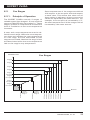
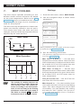
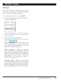
6.2.
Fan Stages
6.2.1. Principle of Operation
The EXPERT 2V4SA controls 2 stages of
variable-speed fans (stages 1-2) and optional
stages of ON/OFF fans (fan stages 3-). These
stages operate in a sequence to increase the
level of ventilation as the room temperature
increases.
Start temperatures of fan stages are defined
with respect to the set point and with respect
to each other. This means that when one of
these values is adjusted, all the consecutive
values are adjusted by the same amount. For
example, if the set point is increased by 1°F,
the start temperature of all fan stages will be
increased by the same amount.
A start and a stop temperature must be defined for each stage. When the room temperature rises and reaches the start temperature
of a fan stage, the fans associated to that
stage are activated; likewise the stage's fans
are deactivated when the room temperature
falls to the stage's stop temperature.
Fan Stages
Ventilation Level
Stage 6
Stage 5
Stage 4
Stage 3
Stage 2
full speed
Stage 2
min speed
Stage 1
full speed
Stage 1
min speed
S6 Start T°
S6 Stop T°
S5 Start T°
S5 Stop T°
S4 Start T°
S4 Stop T°
Room T°
S3 Start T°
# degrees
to full
speed of
stage 2
S3 Stop T°
# degrees
to full
speed of
stage 1
S2 Start T°
Set Point
Min.V.
EXPERT 2V4SA, rev. 07
23
EXPERT 2V4SA
6.2.2. Fan Stage Start Temperature
6.2.3. Minimum Fan Speed
1. From the main menu, select the option that
corresponds to the fan stage you want to
adjust:
1. From the main menu, select the option that
corresponds to the fan stage you want to
adjust:
STAGE 2
or
STAGES 3-
MIN. SPEED/CURVE
(to set the min.fan speed of stage 1)
2. Use the navigation keys to select these
parameters:
(to set the min.fan speed of stage 2)
Stage x
StartT°: 75.0°F
Stop T°: 74.0°F
or
STAGE 2
2. Use the navigation keys to select this
screen:
3. Set the following parameters:
(The parameter adjustment process is explained
in section 3.2 on page 8).
Start T° — Set the start temperature of
the selected fan stage.
Stop T° — Set the stop temperature of the
selected fan stage.
Minimum Speed
40%
3. Set the minimum speed of the fans that
are associated with the selected fan stage
(10 to 100%) *This parameter can only be
modified while the minimum ventilation curve
is off (see section 6.1.4 on page 22).
6.2.4. Adjusting # of Degrees to
Reach 100% of Stages 1 & 2
The minimum difference between
two consecutive start temperatures
is 0.5 °F (0.3 °C).
1. From the main menu, select the option that
corresponds to the fan stage you want to
adjust:
The start temperature of a fan stage
must be greater value than its stop
temperature.
STAGE 1
STAGE 2
2. Use the navigation keys to select the start
temperature screen:
Degrees to 100%
2.0°F
3. Set the number of degrees required for
the selected fan stage to reach its full
speed (0.5°F to 20.0°F (0.3°C and
11.1°C)).
24
EXPERT 2V4SA, rev.07
EXPERT 2V4SA
6.3.
1. From the main menu, select: MIN. SPEED/
CURVE.
Outside Temperature
Compensation
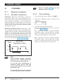
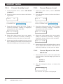
6.3.1. Compensation on Stage 1
Min Speed
The controller can automatically decrease the
minimum ventilation speed (stage 1 minimum
speed) as it gets cold outside.
Min.Vent.
Speed
Outside Temperature
Compensation
on the Min Vent. Speed
Regular
speed
2. Use the navigation keys to select this
screen:
Min Speed Winter
20%
*This parameter is accessible if the outside T°
compensation on the minimum speed of stage 1
speed is enabled in the User Setup Menu.
3. Set the minimum ventilation speed that
should be used in winter to the desired
value. *This parameter can only be modified
if the minimum speed curve is off (see section 6.1.4).
6.3.2. Compensation on the Number of Degrees to Reach Full Speed
of Stages 1 & 2
Winter
Speed
Winter
T°
Summer
T°
Outside
T°
The controller uses the regular minimum
ventilation speed when the outside temperature is at or above the summer's reference
temperature and uses the winter's minimum
ventilation speed when the outside temperature gets below the winter's reference temperature. Refer to the User Setup menu to set
the summer & winter reference temperatures.
Note that the winter speed is related to the
regular speed. This means that if a change occurs in the regular speed, the same variation
will be applied to the winter speed.
The controller can automatically adjust the
number of degrees required to reach the full
speed of the fans (bandwidth) as a function
of outside temperature. If this outside temperature compensation function is enabled
in the User Setup menu, you must specify a
winter bandwidth and a summer bandwidth.
Normally, the winter’s bandwidth should be
greater than the summer’s bandwidth.
# of degrees
to full speed
of stages
1&2
Winter
Setting
# of Degrees to
Full Speed as a
Function of
Outside Temperature
Summer
Setting
Winter
T°
Summer
T°
EXPERT 2V4SA, rev. 07
Outside
T°
25
EXPERT 2V4SA
When a change occurs in the number
of degrees to 100% of stages 1 or 2,
the start temperature of all consecutive fan stages are adjusted by the
same amount.
1. From the main menu, select the option that
corresponds to the fan stage you want to
adjust:
STAGE 1
STAGE 2
2. Use the navigation keys to select the start
temperature screen:
Degrees to 100%
winter
4.0°F
*This parameter is accessible if the outside T°
compensation on the # of degrees to 100% of the
selected stage is enabled in the User Setup Menu.
3. Set the number of degrees required for
the selected fan stage to reach its full
speed in winter (0.5°F to 20.0°F (0.3°C
and 11.1°C)).
26
EXPERT 2V4SA, rev.07
EXPERT 2V4SA
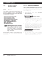
6.4.
Merging Fan Stages
6.4.2. Merging Stages 2 and 3
Refer to the User Setup Menu to enable the Stage Merge options.
6.4.1. Merging Fan Stages 1 & 2
The transition from Stage 1 to Stage 2 can create jumps in the volume of displaced air. This
can be smoothed out by merging stages. When
the merge between stages 1 and 2 is activated,
the speed of Stage 1 fans is decreased to match
the speed of Stage 2 fans when Stage 2 fans
start up. As the temperature increases, the
fan speed of both stages increases to create
a smooth progression. When the temperature
reaches Stage 2 Start Temp + #of degrees to
reach 100% of fan stage 2, Stages 1 and 2
both reach their maximum speed.
The transition from Stage 2 to Stage 3 can
create jumps in the volume of displaced air.
This can be smoothed out by merging two
stages. When the merge between stages 2
and 3 is activated, the speed of stage 2 fans
is decreased when stage 3 fans start up.
As the temperature increases, the speed of
stage 2 fans is increased to create a smooth
progression. When the temperature reaches
stage 3 start temp. + #of degrees to 100% of
stage 3, stages 2 fans reach their maximum
speed once again and stage 3 fans operate
at their full speed.
Merge between Fan Stages 1 & 2
Speed of
Fan Stage 1 (%)
100%
Stage 2
(Min speed)
Stage 1
(Min speed)
Off
0.3°F
Min.
Vent.
Stage 1
Start T°
Ventilation
# of degrees to
reach 100%
of stage 1
Stage 2
Start T°
# of degrees to
reach 100%
of stage 2
Room T°
Merge between Fan Stages 2 & 3
Stage 3 On
Stage 3 Off
Stage 2
(Full speed)
Stage 2
(Min speed)
Stage 2 Min.
Vent. Timer
Stage 2 Off
Stage 2
Start T°
# of degrees to
reach 100%
of stage 2
Stage 3
Stop T°
# of degrees to
reach 100%
Stage 3 of stage 3
Start T°
Room T°
EXPERT 2V4SA, rev. 07
27
EXPERT 2V4SA
6.4.3. Nbr of Degrees to 100% of
Stage 3
The de-icing cycles are only activated
when the outside temperature falls
below a user-defined temperature
unless the controller has no outside
temperature sensor. In that case, the
de-icing cycles are always active.
1. From the main menu, select: STAGES 3-.
2. Use the navigation keys to select this
parameter:
Degrees to 100%
2.0°F
1. From the main menu, select: STAGE 2.
(This parameter is accessible if the merge between stages 2 and 3 is enabled in the User Setup
Menu.)
3. Set the number of degrees required to
reach 100% of Stage 3. This value represents range of temperature over which
stage 2 fans increase or decrease in speed
proportionally to the temperature once
stage 3 fans are activated (see previous
graph). This parameter ranges from 0.5°F
to 20.0°F (0.3°C to 11.1°C).
6.5.
De-icing Stage 2 Fans
Stage 2 fans can automatically be de-iced
in cold weather conditions (or in any conditions if the controller does not use an outside
temperature sensor).
When a de-icing cycle starts, Stage 1 fans are
stopped then stage 2 fans start running at full
speed for 2 seconds. Stage 2 fans then run at
their minimum speed during the de-icing time.
Once the de-icing time has elapsed, stage 2
fans stop running and the regular ventilation
process is resumed.
De-icing
Status
De-icing Timer
ON
OFF
De-icing
time
Cycle
Time
28
EXPERT 2V4SA, rev.07
Settings
Time
2. Use the navigation keys to select these
parameters:
De-icing out T°
41.0°F
*
On:
Cycle:
**
20sec
720min
3. Set the following parameters:
(The parameter adjustment process is explained
in section 3.2 on page 8).
De-icing out T° —Set the outside temperature below which the de-icing cycles must
start. *This parameter is only accessible if the
de-icing function and the outside temperature
sensor are enabled in the User Setup Menu.
On — Set the Time On portion of the
de-icing cycles. It ranges from 0 to 900
seconds. **This parameter is only accessible
if the de-icing function is enabled in the User
Setup Menu.)
Cycle — Set the amount of time that separates two consecutive de-icing cycles. The
cycle time ranges from 1 to 720 minutes
and must be greater than the Time On.
**This parameter is only accessible if the de-icing function is enabled in the User Setup Menu.)
EXPERT 2V4SA
6.6.
0-10V Fan Output
A 0-10V output can be used to activate
supplementary fans. Refer to the User Setup
Menu to enable this kind of output.
A 0 -10V fan output can operate as an
independent ventilation stage and use its
own temperature settings. The graph below
shows how this type of output works.
means that when the set point changes, the
start temperature is adjusted by the same
amount. Refer to the User Setup Menu to tell
if the start temperature of the 0-10V output
must follow the set point or not.
Settings
1. From the main menu, select the option:
Speed of the
0-10V fan
0-10V OUTPUT
Make sure the function of the 0-10V
output is set to "Ventilation" in the
User Setup Menu before adjusting
the parameters below.
Independent 0-10V
Fan Output
2. Use the navigation keys to select these
parameters:
Maximum
Minimum
Stop at
Max T°
Start T°
0%
Room T°
• Below the start temperature: The output
follows a timer and runs at its minimum
speed;
• At the start temperature: The output operates continuously at its minimum speed, and
starts increasing in speed as the temperature
increases;
• At the maximum temperature: The output
reaches its maximum intensity;
StartT° 75.0°F
Min Spd
Max Spd
Max T° 77.0°F
Stop at 79.0°F
On:
Off
Probes
1234
40%
100%
15sec
0sec
3. Set the following parameters:
(The parameter adjustment process is explained
in section 3.2 on page 8).
Start T° — Set the start temperature of
the selected 0-10V output to the desired
value (-40 to 120°F (-40 to 48.9°C)).
• Above the stop temperature: The output
is deactivated.
Min / Man Spd — Set the minimum and
maximum speeds of the 0-10V fan output.
To enable a independent 0-10V fan output,
set the operating mode of this output to
"Ventilation" in the User Setup Menu.
Max T° — Set the temperature at which
the 0-10V fan output reaches its full
speed This parameter ranges from 0.5 to
20°F (0.3°C to 11.1°C) above the start
temperature.
The start temperature of the independent
0-10V fan output can be set as an absolute
value or it can be related to the set point: this
EXPERT 2V4SA, rev. 07
29
EXPERT 2V4SA
Stop T° — Set the temperature over which
the 0-10V fan output is disabled. This parameter ranges from 0.1°F (0.1°C) above
the start temperature to 120°F (48.9°C).
You can also disable this parameter by
decreasing the value until the word "Off"
is displayed.
Time On and Off — Set the timer being used by the 0-10V fan output when
the temperature is lower than the start
temperature. The Time On and Off range
from 0 to 900 seconds in increments of
15 seconds.
Probes — The selected 0-10V fan output
operates according to the average temperature a chosen set of probes. Select
what temperature probes are used for
this purpose. Note that the blinking digits
represent the probes that are being used
by the output.
30
EXPERT 2V4SA, rev.07
EXPERT 2V4SA
7.
MIST COOLING
Settings
The mist output operates according to two
different timers whose activation are based
on the room temperature. Refer to the User
Setup Menu section to enable the mist output
and to see which stage of your controller is
used for this purpose.
1. From the main menu, select: MIST/SOAK.
Mist Timer 1
StartT° 85.0°F
The start and stop temperatures of both mist
timers are directly related to the set point.
This means that when the main set point
changes, the start and stop temperatures are
adjusted by the same amount.
StopT°
On:
Off:
Mist Timer
Mist
Status
83.0°F
1:00min
10:00min
Mist Timer 2
StartT° 88.0°F
(...)
ON
OFF
Time On
Mist
Timer
2. Use the navigation keys to select these
parameters:
Time
Time Off
Mist Shutoff at
95%
These parameters are accessible if the mist output
is enabled in the User Setup Menu.
3. Set the following parameters:
(The parameter adjustment process is explained
in section 3.2 on page 8).
Mist Operation
Mist Timer 1-2 Start T° — Set the start
temperature of both timers. Note that the
start temperature of the second timer must
be at least 0.5°F (0.3°C) higher than the
start temperature of the first timer.
Timer
2
Timer
1
Start T°2
Stop T°2
Start T°1
Stop T°1
Off
Room
T°
The misting & soaking devices are
sharing the same output. When the
clean mode is OFF, this output operates according to the mist parameters; it runs according to the soaking
parameters when the clean mode is
ON. Refer to chapter 4.5 for further
information about the clean mode.
Mist Timer 1-2 Stop T° — Set the stop
temperature and of both timers. Note that
the stop temperature of a given timer must
be at least 0.5°F (0.3°C) lower than its
start temperature.
Time On & Time Off — Set the Time On
and Time Off of both timers.
Mist Shutoff at — Set the humidity level
over which the mist units must stop being
used. This value ranges from 40 to 99%
of humidity. You can disable it by setting
this value to "Off" (100%) *This parameter
is accessible if the humidity sensor is enabled in
the User Setup Menu.
EXPERT 2V4SA, rev. 07
31
EXPERT 2V4SA
8.
SOAKING
The controller can use the mist/soak output
for soaking while being in clean mode. If
the soaking option is enabled, the controller
automatically activates the soaking output
in timer mode when the clean mode starts.
The user can specify the number of soaking cycles that need to be performed or can
choose to make them run continuously.
The misting & soaking devices are
sharing the same output. When
the clean mode is OFF, this output
operates according to the mist parameters; it runs according to the
soaking parameters when the clean
mode is ON. Refer to chapter 4.5
for further information about the
clean mode.
Settings
1. From the main menu, select: MIST/SOAK.
2. Use the navigation keys to select these
parameters:
Soaking Timer
On:
10:00min
Soaking Timer
Off:
50:00min
# Soaking cycle
Cont.
These parameters are accessible if the soaking
output is enabled in the User Setup Menu.
3. Set the following parameters:
Time On & Off — The soaking timer is
made of a Time On and of a Time Off. The
Time On ranges from 0 to 3600 seconds
(1 hour) and the Time Off ranges from 0
to 240 minutes (4 hours). Set these parameters to the desired values.
# of soaking cycles — Select the number of soaking cycles that need to be
performed or select “cont.” to run these
cycles continuously.
32
EXPERT 2V4SA, rev.07
EXPERT 2V4SA
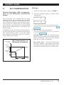
9.
RH COMPENSATION
Relative Humidity (RH) Compensation on the Minimum Ventilation
Speed
The controller can compensate for high
humidity levels by increasing the minimum
ventilation fan speed. As the RH level rises,
the controller increases the minimum ventilation speed to compensate for the change
and reaches the maximum compensated
speed when the RH level is 10% above the
RH set point.
In addition, if the controller is already operating with the minimum ventilation mode when
this compensation starts, it will then make
the minimum ventilation fans run continuously rather than cycled.
Min. Vent
Speed
RH Compensation on
Minimum Ventilation
1. From the main menu, select: STAGE 1.
2. Use the navigation keys to select these
parameters:
Humidity setp
65%
*
RH speed comp.
60%
**
* These menus are accessible if the RH Compensation function is set to "Ventilation" in the User
Setup Menu.
3. Set the following parameters:
(The parameter adjustment process is explained
in section 3.2 on page 8).
Humidity setp — Set the humidity level
over which the minimum ventilation speed
starts increasing. This set point ranges
from 40 to 100% of humidity.
RH speed comp — Set the speed that
must be added to the regular minimum
ventilation speed when the humidity level
exceeds the set point by more than 10%.
Added
Speed
Compensated
Speed
Settings
Regular
Speed
Off
10%
RH Set Point
RH Level
(%)
EXPERT 2V4SA, rev. 07
33
EXPERT 2V4SA
10.2.
Regular Heating Stages
Stages and can be used to control heating
units. If only one heating stage is enabled,
stage # will then be assigned for this purpose
(refer to the stage combination table in the
User Setup Menu).
A heating stage starts running when the
average room temperature gets lower than
the stage's start temperature; likewise, the
heating stage stops when the room temperature gets higher than the stage's stop
temperature.
Heating Stages
Heating
level
Heat.
Stage 2
With the zoned heating functions, each heating stage can operate according to the average temperature of a chosen set of sensors.
When enabling this feature in the User Setup
menu, the controller automatically assigns
sensors 1 and 2 to the first heating stage
and sensors 3 and 4 to the second.
To enable zoned heating, activate
the "Use zoned heaters" option in
the User Setup Menu.
10.3.
The heating stages can run in timer mode
and according to two different timers based
on the room temperature. The graph below
shows how the heating timers work.
Heating Timers
Timer
Status
EXPERT 2V4SA, rev.07
Room
T°
Off
Start T°
Timer 2
Stop T°2
Timer 1
Start T°2
Off
Stop T°1
Timer 2
Start T°1
Heat.
Stage 1
34
Heating Timers
Stop T°
Timer 1
10.1.
Zoned Heating
Start T°
Timer 1
HEATERS
Stop T°
Timer 2
10.
Room
T°
EXPERT 2V4SA
10.4.
Heater Settings
10.5.
1. From the main menu, select: HEATERS.
2. Use the navigation keys to select these
parameters:
Heater 1
StartT° 73.0°F
StopT°
or 0-10V Heater
The controller has one 0-10V output that
can either be used to control heaters, fans or
actuators. This section explains how a 0-10V
heater works.
Heat 1 Timer 1
StartT° 73.0°F
0-10V Heater
Intensity (%)
(...) Idem for Heater 2
75.0°F
StopT°
75.0°F
On:
Off:
1:00min
1:00min
Heat 1 Timer 2
StartT° 71.0°F
StopT°
On:
Off:
73.0°F
1:00min
1:00min
(...) Idem for Heater 2
(These parameters are accessible if at least one
heating stage is enabled in the User Setup Menu.)
3. Set the following parameters:
(The parameter adjustment process is explained
in section 3.2 on page 8).
Max
Min
Off
Max T°
T° of
Min T° Stop T° 0-10V
heater
probes
The 0-10V heater start at its minimum intensity when the temperature falls below its start
temperature. It then increases in intensity as
the temperature decreases and reaches its
maximum intensity when the temperature gets
lower than the Max. Temperature value.
Start T° — Set the temperature below which
each heating stage starts. If you are using
heating timers, set this temperature separately for both timer of each heating stage.
Stop T° — Set the temperature over which
each heating stage stops. If you are using
heating timers, set this temperature separately for both timer of each heating stage.
Note that the stop temperature for a given
stage musts be at least 0.3°F higher than
its start temperature.
Time On & Off — If the heating timers are
enabled, set the Time On and Off of both
timers for each heating stage.
EXPERT 2V4SA, rev. 07
35
EXPERT 2V4SA
Settings
1. From the main menu, select the option:
0-10V OUTPUT /CURVE
Make sure the function of the selected 0-10V output is set to "Heating" in the User Setup Menu before
adjusting the parameters below.
2. Use the navigation keys to select these
parameters:
Min T°
Max T° 73.0°F
Stop at 76.0°F
75.0°F
MinHeat
MaxHeat
Stop at day
Probes
1234
Probe average T°
73.0°F
10%
100%
Max T° — Set the temperature at which
the 0-10V heater reaches its maximum
intensity. This parameter ranges from
0.5 to 20°F (0.3°C to 11.1°C) below the
output’s minimum temperature.
Min/Max Heat — Set the minimum and
maximum intensity of the 0-10V heating
output (from 0 to 100%).
Stop T° — Set the temperature over
which the 0-10V heater is disabled. This
parameter ranges from 0.5 to 20°F (0.3°C
to 11.1°C) above the output's minimum
temperature.
Off
3. Set the following parameters:
(The parameter adjustment process is explained
in section 3.2 on page 8).
Minimum T° — Set the temperature below
which the 0-10V heating output starts
operating at its minimum intensity (-40 to
120°F (-40 to 48.9°C)). This parameter
can be defined as an absolute value or
it can be related to the set point, which
means it is automatically adjusted when
the set point changes. Refer to the User
Setup Menu to set the proper operating
mode ("0-10V follows set point").
36
If the 0-10V heat curve is used, the
temperature at which the 0-10V
heating output starts must be defined
separately for each step of the curve.
See “0-10V Heating Curve” on page
38 for further information about
this curve.
EXPERT 2V4SA, rev.07
Stop at day — Set the animal age over
which the 0-10V heating output must stop
being used. See “Setting the Day Number”
on page 10 to view/modify the current
day number.
Probes — The 0-10V heating output operates according to the average temperature
a chosen set of probes. Select what temperature probes are used for this purpose.
Note that the blinking digits represent the
probes that are being used by the output.
Probe average T° — This is the average
temperature reading of the temperature
probes that were chosen above.
EXPERT 2V4SA
10.6.
0-10V Heat Mat
When it is used to control heat mats, the
0-10V output runs at its maximum intensity
when the temperature of a chosen group of
probes gets lower than the heat mat set point.
Heat Mats
Heat mat
Status
Off
Heat Mat
Set point
Heat Mat
T°
Settings
1. From the main menu, select the option:
0-10V OUTPUT /CURVE
Make sure the function of the selected 0-10V output is set to “Heat
mat” in the User Setup Menu before
adjusting the parameters below.
2. Use the navigation keys to select these
parameters:
Heat mat setp
80.5°F
Stop at day
Probes
1234
Probe average T°
73.0°F
Heat Mat Set Point T° — Set the temperature below which the 0-10V heat mat turns
on. This heating set point ranges from -40
to 120°F (-40 to 48.9°C).
If the 0-10V heat curve is used, the
temperature at which the 0-10V
heating output starts must be defined separately for each step of the
curve. See “0-10V Heating Curve” on
page 38 for further information about
this curve.
0.5°F
On
3. Set the following parameters:
(The parameter adjustment process is explained
in section 3.2 on page 8).
Stop at day — Set the animal age over
which the 0-10V heating output must stop
being used. See “Setting the Day Number”
on page 10 to view/modify the current
day number.
Probes — The 0-10V heating output operates according to the average temperature
a chosen set of probes. Select what temperature probes are used for this purpose.
Note that the blinking digits represent the
probes that are being used by the output.
Probe average T° — This is the average
temperature reading of the temperature
probes that were chosen above.
Off
EXPERT 2V4SA, rev. 07
37
EXPERT 2V4SA
10.7.
0-10V Heating Curve
The controller can automatically change the
temperature at which the 0-10V heater (or
heat mat) starts over time by using a curve.
This heating curve is optional. Refer to the User
Setup menu in section 4.4 to enable it.
Settings
1. From the main menu, select: 0-10V OUTPUT / CURVE.
2. Use the navigation keys to select this
screen:
Min Heat T°
74.0
73.5
72.0
71.5
71.0
70.5
70.0
65.5
65.0
64.5
64.0
1 5
0-10V Heat Curve
1
74.0°F
(This screen is accessible if the set point curve
is enabled in the User Setup Menu).
3. Set the following parameters:
(The parameter adjustment process is explained
in section 3.2 on page 8).
10
1. day
Setp
1
74.0°F
2. day
Setp
5
72.5°F
14 19 24 28 33 38 42 47Day
The 0-10V heat curve is made of 10 steps.
Each step specifies a day number and a start
temperature of the 0-10V heating output for
that day. Once it is activated, the controller
changes this start temperature every hour in
a linear fashion between consecutive steps of
the curve. When the last step is reached, the
controller keeps using the start temperature
associated with that day.
Notes
Certain restrictions apply to reduce the
risk of errors:
1. The highest day number is 365.
2. Decreasing day numbers is not allowed.
3. Increasing heater set points is not allowed.
4. All ten steps must be specified. If you
don’t need ten different steps, repeat the
last temperature for each unnecessary step.
Refer to section 4.2 on page 10
to set the current day number.
38
1. day
Setp
EXPERT 2V4SA, rev.07
...
10. day
40
Setp
65.0°F
Curve status
Off
Day numbers — Set the day at which each
curve step starts.
Setp — Assign a temperature set point (start
temperature of the heating output) to each
step of the curve.
Curve status — Select “Yes” to enable the
curve (or “No” to disable it). Once the curve
is on, the controller automatically adjusts
the set point between consecutive points of
the curve; for this reason, curve steps cannot be modified while the curve is running.
If all curves are disabled (Min.Vent,
Set Point & 0-10V Heat curves), the
controller will automatically set the day
number back to 1 day when a curve
is being activated.
EXPERT 2V4SA
11.
AIR INLET & CHIMNEY DAMPERS
This over-opening stage is used to direct the
airflow more efficiently during periods of
warm weather.
11.1.
Principle of Operation
The air inlet can either reach its over-opening
position right away when the room temperature reaches a certain point or it can reach its
over-opening position gradually as the room
temperature departs from the start temperature of the last fan stage. In either case, the
inlet reaches its full over-opening position at:
On T° of the last fan stage + Over-opening
bandwidth. Refer to the User Setup Menu to
enable the Over-Opening function.
The controller can control the opening of 1 air
inlet and of a 0-10V chimney damper.
When using the inlet or chimney output,
the user must associate an actuator position
with the start-up of each fan stage. As the
room temperature increases and new stages
are activated, the air inlet will open or close
accordingly.
Inlet opening in minimum ventilation:
The inlet is at its closed position (step 0) during
the “Time Off” portion of a minimum ventilation
cycle and opens to its minimum ventilation
position (step 1) during the “Time On”.
Over-opening of the air inlet: A supplementary stage can be defined in order to continue
opening the air inlet beyond the activation
temperature of the last ventilation stage.
Low Temperature Override — The low temperature override function allows bypassing
the inlet's normal operation when the room
temperature is too cold. When this override
function is enabled, the inlet directly goes
to a user-defined position when the room
temperature falls below a user-defined temperature limit (Low Override Temperature).
Refer to the User Setup Menu to activate this
function and to set the low temperature limit.
Opening of the Air Inlets &
Chimney Dampers
Actuator Position
OverOpening
(opt.)
or
Last Stage
Opening
Gradual or
instant
over-opening
(opt.)
Step 3
Step 2
Hi
Step 2
Step 1
Hi
Step 1
over-open.
bandw.
Room T°
Last stage
Start T°
Last stage
Stop T°
S3 Stop T°
# degrees
to full
speed
of stg2
Stage 2
start T°
# degrees
to full
speed
of stg1
S3 Start T°
Min.V.
Set Point
Step 0
EXPERT 2V4SA, rev. 07
39
EXPERT 2V4SA
11.2.
Inlet & Chimney Settings
1. From the main menu, select the option that
corresponds to the type of air inlet you
want to adjust:
INLET
0-10V OUTPUT /CURVE
If you are selecting a 0-10V output,
make sure the function of this output is set to “Chimney” in the User
Setup Menu before adjusting the
parameters below.
2. Use the navigation keys to select the following parameters:
Min Spd
St. 0
45%
10%
St. 1
St. 1Hi
20%
30%
...
St.
Total run time
1:15min
Max opening
100%
Degrees to max
opening
2.0°F
Accuracy
+/- 2sec
...
40
Min Spd — During the minimum ventilation cycles and in stage 1, the inlet will
use its minimum ventilation position (Step
1) as long as the fan speed is lower than
the “Min Speed” value. Once the minimum
speed is reached and keeps increasing the
inlet will open further towards Step 1 Hi
opening. Set the minimum fan speed to
the desired value.
St.x — Assign an actuator opening (in %)
with the startup of each fan stage.
St.x Hi — Assign the actuator opening (in
%) that must be used when a variable fan
stage reaches full speed
Total run time (inlet only) — Enter the
exact time that is required to reach the
actuator’s maximum limit switch. The
controller will limit the opening of the inlet
according to this parameter value.
80%
3. Set the following parameters:
(The parameter adjustment process is explained
in section 3.2 on page 8).
Under run open
time
0sec
EXPERT 2V4SA, rev.07
Max opening (inlet only) — Set the opening
that is reached beyond the start temperature of the last ventilation stage.*This parameter is accessible if the over-opening function
is enabled in the User Setup Menu.
Degrees to max opening (inlet only)— Set
the temperature range over which the actuator opens beyond its last stage opening
towards its maximum opening (see previous graph). This parameter ranges from
0.5 to 20°F (0.3 to 11.1°C).*This parameter
is accessible if the over-opening function is enabled in the User Setup Menu.
Accuracy (inlet only)— To prevent the
actuator from flickering, a minimum
opening or closing command is required
for the actuator to start moving. Set this
parameter to the desired value (from 1 to
15 seconds).
EXPERT 2V4SA
Under run open time (inlet only) — When
an inlet timer ends, it may take a few
seconds for the actuator to actually stop
moving. For this reason, the controller can
switch off the actuator’s motor slightly
before its time for the actuator to reach
its exact moving time without exceeding
it. This parameter ranges from 0 to 3 seconds. *This parameter is only accessible with
the installer password.
11.2.1.Actuator Reset
No reset can be made when the
outside temperature falls below a
user-defined value. This limitation
applies to both automatic & manual
resets.
Resetting the actuator’s position is used to
clear accumulated time offsets caused by the
frequent openings and closings of the inlet.
The controller resets the actuator’s position
at regular intervals to make sure the inlet
position is always accurate. *The actuator reset
is not required for the 0-10V chimney.
The inlet RESET pilot light flashes
while an actuator is being reset.
This reset is performed automatically according to one of these two methods:
1. Reset the minimum position only
(Close mode)
Each time a reset is performed, the inlet
totally closes. Once the actuator’s position
is reset, the inlet returns to its previous
position.
2. Reset toward the nearest position
(Open/Close mode)
If the current inlet position is higher than 50%
at the reset time, the controller fully opens
the inlet to reset the actuator’s position; if
the current inlet position is lower than 50%,
the controller closes the inlet to perform the
reset. This way, the inlet never closes when
the room temperature already asks for a wide
opening.
Make sure limit switches are located
at both ends of the actuators when
using this resetting method.
EXPERT 2V4SA, rev. 07
41
EXPERT 2V4SA
1. From the main menu, select: INLET.
2. Use the navigation keys to select the following menus:
Reset Mode
Open/Close
Reset 1 5:00 PM
Reset 2 5:00 PM
Reset 3 5:00 PM
Reset 4 5:00 PM
Reset
Now?
No
Reset delay
2 min
Disable if OutT°
is Below 10.0°F
(These menus are accessible if an inlet is enabled in
the User Setup Menu).
3. Set the following parameters:
Reset Mode — Select the desired reset
mode: “Open/Close” to reset the actuator
toward its nearest position; select “Close”
to reset the actuator toward its closed
position only or select “Off” to disable the
automatic reset.
Reset 1,2,3,4 — Set the times at which
resets are performed. The inlets reset up
to 4 times per day when the reset times
are set to different times. Set all 4 reset
times to the same time if you only want
the inlets to reset once.
Reset now? — Select “Yes” to reset the
actuator’s position now.
42
EXPERT 2V4SA, rev.07
Reset delay — During a reset, the controller
opens or closes the inlet during this delay, or
up until a limit switch is reached. The reset
delay should be set to the same time value
or higher than the total opening time (as
defined in previous section).
Disable if Out.T° is Below — To prevent
the inlet from closing against ice, the
controller can stop all inlet resets when
it is too cold outside. Set the outside
temperature below which inlet resets are
forbidden. Note that the inlet can still be
reset manually regardless of the outside
temperature. *This parameter is accessible if
an outside temperature sensor is enabled in the
User Setup Menu.
EXPERT 2V4SA
11.2.2.Manual Opening of the
Actuators
The controller allows you to change the position of the actuators manually. When an inlet
or chimney damper is controlled this way, the
controller simply stops controlling the output.
1. From the main menu, select the option that
corresponds to the type of air inlet you
want to adjust:
INLET
0-10V OUTPUT/CURVE
If you are selecting a 0-10V output,
make sure the function of this output is set to "Chimney" in the User
Setup Menu before adjusting the
parameters below.
2. Use the navigation keys to select the following menu:
Opening
Mode
35%
Open
3. Set the Mode to the desired status: Open,
Close, Off or Auto. Do not forget to return to the automatic control mode afterwards so
that the controller can take back
control of this output.
EXPERT 2V4SA, rev. 07
43
EXPERT 2V4SA
11.3.
Static Pressure Compensation on the Inlet
A compensation can be used to ensure a certain uniformity in the static pressure level in
the room. This static pressure compensation
allows opening or closing inlets further when
the static pressure level gets out of range.
When the static pressure level exceeds the
normal range (above the Hi Pressure Set
point or below the Lo Pressure Set Point),
the controller waits for the Compensation to
make sure this unusual pressure condition is
not temporary. If the pressure is still out of
range after this delay has elapsed, the inlet
compensation (%) is applied on the opening
of all inlets: they close further by their respective compensation value (%) when the pressure level is too low [point A on the graph] or
open further by their compensation value (%)
when the pressure level is too high [point C
on the graph]. The controller then waits for
the Compensation once again. If the pressure level is still out of range afterwards, the
opening compensation is applied once more.
This cycle is repeated up until the pressure
gets back in the normal range or until a new
stage starts. When the pressure level gets
back to the normal range [points B & D on
the graph], all inlets keep their compensated
position until the beginning of a new stage.
No compensation is applied on the inlet opening when a new stage starts
This compensation will not be made if
the static pressure probe is defective.
Static Pressure Compensation
on the Inlet Opening
Static Pressure
Increase
inlet
opening
Hi Set
Point*
Keep
inlet
position
Lo Set
Point*
Decrease
inlet
opening
44
EXPERT 2V4SA, rev.07
Comp.
Delay
Inlet opens further
(by comp value%)
Comp.
Delay
Inlet opens further
(by comp value%)
Comp.
Delay
Inlet opens further
(by comp value%)
Inlet closes further
(by comp value%)
Comp.
Delay
Inlet closes further
(by comp value%)
Comp.
Delay
Inlet closes further
(by comp value%)
Comp.
Delay
Time
EXPERT 2V4SA
Settings:
The static pressure compensation starts
when the static pressure level exceeds the
Hi or Lo static pressure set points.
1. From the main menu, select: INLET.
2. Use the navigation keys to select the following parameters:
Low SP
High SP
Stat. P compens
5%
Compens.delay
30 sec
.00"WC
.10"WC
*These parameters are accessible if the static
pressure compensation feature is enabled in the
User Setup menu.
3. Set the following parameters:
(The parameter adjustment process is explained
in section 3.2 on page 8).
Low SP & High SP — Set the static pressure level below and above which the
static pressure compensation must be
applied on the inlet opening.
Stat. P compens — Select the opening
percentage that must be added or removed
when the static pressure compensation is
applied on the inlet openings. This parameter ranges from 0 to 10%. *Note that this
compensation is never applied more than four
times on the inlet opening.
Compens. delay — Each time this delay
has elapsed and the pressure exceeds the
normal range, the static pressure compensation is applied on the inlet opening. This
parameter ranges from 0 to 900 seconds.
EXPERT 2V4SA, rev. 07
45
EXPERT 2V4SA
12.
12.1.
MONITORING
FUNCTIONS
Alarms
The alarm output is activated when an
abnormal situation occurs. Each triggered
alarm is logged in a history menu and must
be acknowledged by the user. The alarm
conditions are as follows:
-
Defective temperature probe;
Defective outdoor probe;
Defective humidity probe;
Defective static pressure probe;
Hi/Low/Critical temperature;
Clean mode low temperature;
Water spill alarm;
Hi/Low Water usage.
When an alarm is active, its respective pilot light turn on; when an alarm
is no longer active but has not been
acknowledged by the user, its pilot
light flashes. Refer to the following
section of this manual to acknowledge the alarms.
Another alarm situation occurs when power
to controller fails. In this case, the alarm relay
is activated.
46
EXPERT 2V4SA, rev.07
12.1.1.Managing the Alarms
The controller has an alarm monitoring menu
which contains a list of all alarms that are
currently active and a list of all alarms that
are no longer active but that have not been
acknowledged yet.
1. From the main menu, select: ALARMS
[MONITORING].
Active Alarms
Water Spill
Rolling active
alarm conditions
The first screen shows the active alarm
conditions. If there is more than one active alarm, the alarm messages will be
displayed in turn.*The message “No Alarm”
is displayed if there is currently no active alarm.
2. Press the down-arrow key once to select
the alarm log. All unacknowledged alarm
conditions are displayed in turn (unacknowledged alarms represent the alarm
conditions that are no longer active).
T° Pr.1 defect
Unacknowledged
Rolling unackn.
alarm conditions
3. Set the status of the unacknowledged
alarms to “Acknowledged” to acknowledge all the alarms at the same time.
EXPERT 2V4SA
12.1.2.Alarm Conditions
12.1.2.2. Water Alarms
12.1.2.1. Temperature Alarms
• Water Spill Alarms:
A water spill alarm sets off when the water
consumption exceeds a certain limit. This limit
can be adjusted from 0 to 1,000 gallons or
liters per 15 minutes. The alarm is activated if
a greater amount of water is detected within
the 15 minute interval. A separate water spill
limit can also be defined for day and night.
The following diagram explains how temperature alarms are detected:
Alarm
Limits
(T°)
High
Alarm
Limit
Detection of
Temperature Alarms
• Water Consumption Alarms:
When the percent difference in water consumption between the last 24-hour period
and the previous 24-hour period is greater
than a given maximum value, an alarm is
set off.
Hi T°
alarm
Set
Point
Water Consumption
Low
Alarm
Limit
Room T°
When the average room temperature exceeds the high temperature alarm setting, a
high temperature alarm is generated. When
the average room temperature drops below
the low temperature alarm setting, a low
temperature alarm is generated. Although
these settings are entered by the user as
absolute values, they are defined relative to
the current set point and are automatically
adjusted by the controller when the set point
changes. This means, for example, that when
the controller switches to the nighttime set
point, the high and low temperature alarms
are readjusted using the same offset from the
daytime set point.
The situation is slightly different when the outside temperature is greater than the set point.
In this case, the high alarm set point is replaced
by the outside temperature as the reference
point. Another parameter, called the critical
temperature, is defined to continue monitoring
the indoor temperature for high temperatures.
When the indoor temperature reaches the critical high temperature (defined as an absolute
value), an alarm is set off.
Previous 24h
Last 24h
Time
Now
The high and low water consumption alarm
limits are defined as follows:
• Case #1: If more water has been consumed
in the last 24 hours than in the 24 hours
that precede, the controller will determine
how much more water has been consumed
and will convert this value in percent. If the
surplus (in %) is higher than the “High Alarm”
limit, the controller will set off an alarm.
Last 24h - Previous 24h x 100 > Hi Alarm
Previous 24h
• Case #2: If less water has been consumed
in the last 24 hours than in the 24 hours that
precede, the controller will determine how
much less water has been consumed and will
convert this value in percent. If the deficit (in
%) is higher than the “Low Alarm” limit, the
controller will set off an alarm.
Previous 24h - Last 24h x 100 > Lo Alarm
Previous 24h
EXPERT 2V4SA, rev. 07
47
EXPERT 2V4SA
Before it can start monitoring the
water consumption alarms, the
controller needs to gather consumption data for 48 hours in a row (no
consumption alarm can be detected
within this 48-hour delay). This 48hour delay starts when enabling the
water meter in the User Setup Menu.
12.1.3.Alarm Settings
1. From the main menu, select: ALARMS.
2. Use the navigation keys to select the following parameters:
Low:
High:
Critical high:
95.0°F
Clean mode low
temp.
38.0°F
Water spill set1
#/15min
50l
From
To
Lo Water usage
Off%
Hi Water usage
Off%
65.0°F
95.0°F
6:00A
10:00P
3. Set the following parameters:
(The parameter adjustment process is explained
in section 3.2 on page 8).
Low & High Temperature Limits — Set the
room temperature below and above which
a temperature alarm must be triggered. The
low limit can be adjusted from 40°F to 0.5°F
(22.2 to 0.3°C) below the set point and the
high limit from 0.5°F to 40°F (0.3 to 22.2°C)
above the set point. *A change in the set point will
change these values by the same amount.
Critical Temperature — Set the absolute
maximum temperature that is allowed in
48
EXPERT 2V4SA, rev.07
the room. This parameter ranges from
–40 to 120ºF (-40 to 48.9ºC). *Accessible
if the outside temperature sensor is enabled in
the User Setup Menu.
Clean mode — Set the temperature below
which a temperature alarm is set off in
clean mode.
Water spill set 1 — Set the first maximum
amount of water that can be consumed
in a 15-minute delay. *This parameter is
accessible if the water meter is enabled in the
User Setup Menu.
From / To — Set the period of time during
which the first water spill limit is being used.
Water spill set 2 — Set the second
maximum amount of water that can be
consumed in a 15-minute delay. *This
parameter is accessible if the water meter is
enabled in the User Setup Menu.
Water Lo Alarm Usage — An alarm is set
off if the water consumption measured
by a water meter in the last 24 hours is
too low compared to the consumption
measured in the 24 hours that precede. To
disable this monitoring function, decrease
the parameter value until the word “Off ”
is displayed. *This parameter is accessible if a
water meter is enabled in the User Setup Menu.
See “Water Alarms” on page 47 for more
information on this alarm limit.
Water Hi Alarm Usage— An alarm is set
off if the water consumption measured
by a water meter in the last 24 hours is
too high compared to the consumption
measured in the 24 hours that precede. To
disable this monitoring function, decrease
the parameter value until the word “Off ” is
displayed. *This parameter is accessible if a
water meter is enabled in the User Setup Menu.
See “Water Alarms” on page 47 for more
information on this alarm limit.
EXPERT 2V4SA
Reset Water Alarm ? — If a water alarm
is on (high or low water consumption
or water spill alarm), select “Yes” to acknowledge the alarm condition. Note that
when a reset is made, the controller needs
48 hours to gather new consumption data
before it can start monitoring the high/
low water consumption alarms again (no
consumption alarms can happen by the
end of this 48-hour delay). *This parameter
is accessible if a water alarm is on.
12.2.
Water Consumption
12.2.1. History
The controller provides a pulse input to
monitor the water consumption. The water
consumption is logged into an history menu
for the current day and for the past 6 days.
1. From the main menu, select: WATER
HISTORY.
01/31/0X
01/30/0X
1241l
6189l
(This menu is accessible if the water meter is
enabled in the User Setup Menu.)
2. The water consumption history is displayed Press the down-arrow key to scroll
down the water consumption history.
12.2.2.Water Consumption of the
Last 48 Hours
1. From the main menu, select: LAST 48HOUR WATER.
L.24Hr Water
usage:
123L
The water consumption of the last 24 hours
is displayed. *This menu is accessible if the water
meter is enabled in the User Setup Menu.)
2. Press the down-arrow key to see the water consumption of the previous 24 hours
(i.e. 24 hours that are preceeding the last
24 hours).
P.24Hr Water
usage:
234L
EXPERT 2V4SA, rev. 07
49
EXPERT 2V4SA
12.3.
Heater Run Time History
The controller has an history in which run
times of the heating units are logged in for
the past 6 days.
13.
CURRENT
CONDITIONS
13.1.
Current Room Temperature
1. From the main menu, select: HEATER
RUN TIME.
*This menu is accessible if at least one heating
stage is enabled in the User Setup Menu.
The room temperature is the average reading
of the temperature probes that have been
chosen for this purpose in the User Setup
Menu.
1. From the main menu, select: ROOM
TEMPERATURE.
Heater 1
01/01/0X
2:30
2. The run time of the first heating stage is
displayed along with the time and date.
Press the down-arrow key to scroll down
the heater run time history.
2. Room T°
76.5 °F
Pr.Act:1234
The average temperature probes are flashing on screen.
3. Press the down-arrow key once. The
minimum temperature recorded today is
displayed along with the time and date.
Room T° 01/01/0X
Min 72.2 1:10A
4. Press the down-arrow key once again.
The maximum temperature recorded
today is displayed along with the time
and date.
Room T° 01/01/0X
Max 76.2 10:25A
5. Keep pressing on the down-arrow key
to look at the minimum and maximum
temperature readings of the past six days.
50
EXPERT 2V4SA, rev.07
EXPERT 2V4SA
13.2.
Probe Temperatures
Temperature readings of each individual
probe can be displayed as follows. The readings of each activated probe are displayed,
whether they are assigned for the average
room temperature or not.
1. From the main menu, select: PROBE
TEMPERATURE.
2. Press the down-arrow key once. The
current reading of each activated probe
is displayed.
1: 74.3
3: 77.1
2: 75.0
4: 77.3
3. Press the down-arrow key once. Today’s
minimum reading of probe 1 is displayed,
along with the time and date.
Probe1 01/01/0X
Min 73.3 12:30A
4. Press on the down-arrow key once again.
Today’s maximum reading of probe 1 is
displayed, along with the time and date.
Probe1 01/01/0X
Max 75.1 3:30P
13.3.
Outside Temperature
The following procedure shows how to display the current outside temperature and how
to see the minimum and maximum outside
temperature readings of the past six days.
1. From the main menu, select: OUTSIDE
TEMPERATURE.
2. Press the down-arrow to select the outside
temperature reading.
Out T°
55.2°F
* This reading is accessible if the outside temperature probe is enabled in the User Setup Menu.
3. Press the down-arrow key once. Today’s
minimum outside temperature reading is
displayed, along with the time and date.
4. Press the down-arrow key once again.
Today’s maximum outside temperature
reading is displayed, along with the time
and date.
5. Keep pressing the down-arrow key to display the minimum and maximum outside
temperature readings of the past six days.
5. Keep pressing the navigation down-arrow
key to display the minimum and maximum
temperatures of the past six days for each
remaining probe.
EXPERT 2V4SA, rev. 07
51
EXPERT 2V4SA
13.4.
Current Humidity Level
13.5.
Current Pressure Level
1. From the main menu, select: RELATIVE
HUMIDITY.
1. From the main menu, select: STATIC
PRESSURE.
2. Press the down-arrow to select the following screen.
2. Press the down-arrow to select the following screen.
Humid.
50%
(This reading is accessible if the humidity sensor
is enabled in the User Setup Menu).
Stat. P
.05"WC
(This reading is accessible if the static pressure
sensor is enabled in the User Setup Menu).
3. Press the down-arrow key once. Today’s
minimum humidity reading is displayed,
along with the time and date.
3. Press the down-arrow key once. Today’s
minimum humidity reading is displayed,
along with the time and date.
Humid. 01/01/01
Min 25% 12:00A
Stat P 31/12/XX
Min .02 12:00A
4. Press the down-arrow key once again.
Today’s maximum humidity reading is
displayed, along with the time and date.
4. Press the down-arrow key once again.
Today’s maximum humidity reading is
displayed, along with the time and date.
5. Keep pressing the navigation down-arrow
key to display the minimum and maximum
humidity readings of the past six days.
Stat P 31/12/XX
Max .07 14:00A
5. Keep pressing the navigation down-arrow
key to display the minimum and maximum
humidity readings of the past six days.
13.6.
Current Speed of the Variable Fans
1. From the main menu, select the option that
corresponds to the fan stage you want to
consult:
STAGE 1
STAGE 2
2. Use the navigation keys to select this
screen:
52
EXPERT 2V4SA, rev.07
Current speed
100%
The current fan speed is displayed.
EXPERT 2V4SA
14.
TECHNICAL SPECIFICATIONS
Supply: ����������������������115/230 VAC (-18%, +8%), 50/ 60Hz, overload and overvoltage protection fuse F1-1A fast blow.
Alarm: �����������������������ON-OFF output, 30VDC, 24VAC.
Temperature Probes������Low voltage ( < 5V), isolated from the supply. Operating range: -40.0° to
120.0°F (-40.0° to 48.9°C). Accuracy: 1.8°F (1°C) between 41° and
95°F (5° and 35°C).
Rel. Humidity Input: ������4 to 20mA current loop
Static Pressure Input: ����4 to 20mA current loop
Water Meter Input: �������Input pulse width > 12ms.
0-10V Output:�������������30mA max
Stage 1: ��������������������Variable output, 50/60Hz, 115VAC 1/2HP (373W), 230VAC 1.5HP
(1120W), 10 Amp Max. Fuse F2-15A slow blow.
Stage 2: ��������������������Variable output, 50/60Hz, 115VAC 1/2HP (373W), 230VAC 1.5HP
(1120W), 10 Amp Max. Fuse F3-15A slow blow.
Stage 3: ���������������������ON/OFF output, 50/60Hz, 115VAC 1/4HP (187W), 230VAC 1/2HP (373W),
10 A Res. Max, 30VDC 5A Ind. Heating or cooling. Fuse F6-15A slow blow.
Stage 4: ����������������������ON/OFF output, 50/60Hz, 115VAC 1/4HP (187W), 230VAC 1/2HP (373W),
10 A Res. Max, 30VDC 5A Ind. Heating or cooling. Fuse F5-15A slow blow.
Actuator (winch): ��������� Open/Close output, 50/60Hz, 115VAC (0.17HP 124W), 230VAC (0.5HP
373W), 30 VDC 5A Ind. Fuse F4-5A slow blow.
Enclosure: �����������������ABS, moisture and dust-tight.
The room temperature where the controller is located must always remain between 32° and
104°F (0 and 40°C). For indoor use only !
EXPERT 2V4SA, rev. 07
53
EXPERT 2V4SA
15.
MEMORY CARD
The memory card is used to create a backup
copy of your controller’s configuration. The
card is also useful to transfer the configuration of one controller to another controller of
the same type.
The switch on the card is used to lock or to
unlock the card ( = locked, = unlocked).
Turn off power each time you open
the controller’s enclosure. This prevents accidental exposure to areas
of high voltage.
Memory
card
6. Use the up and down navigation buttons
to select the proper type of transfer:
Memory Card To Controller:
To transfer the memory card’s content into
the controller, select the “Mem.Card –> Ctrl”.
When it is selected, simultaneously press
the up and down adjustment buttons to start
the transfer.
Mem.Card –> Ctrl
to start
Controller To Memory Card:
To save the controller’s configuration into the
memory card, select the “Ctrl –> Mem. Card”
menu. Once it is selected, simultaneously
press the up and down adjustment buttons
to start the transfer.
Ctrl –> Mem.Card
to start
Lock Switch
Connector
Electronic
board
To Transfer a Configuration:
1. Turn off power to the controller.
2. Open the latch and lift the controller’s
cover.
3. If you are about to copy the controller’s
configuration on the memory card, make
sure the card’s switch is at the unlocked
position.
4. Insert the card in the J2 connector located
on the electronic board inside the controller. The lock switch on the card must face
down as illustrated.
5. Close the cover then reapply power to the
controller. The transfer menu should be
shown on screen (if this is not the case,
simultaneously press the up and down
menu select keys for 3 seconds to display
this menu).
54
EXPERT 2V4SA, rev.07
7. When the transfer is over, simultaneously
press and hold the up and down menu select
keys for 5 seconds to exit from the transfer
menu and then remove the memory card
from the connector as follows:
■Turn
■
off power to the controller;
■Open
■
the controller’s cover;
■Remove
■
the card from the connector;
■Close
■
the cover then reapply power to
the controller.
8. Lock the card’s switch
if required.
Remove the memory card from the
connector when the transfer is over!
The controller will not warn you if the transfer
is incorrect. Respect the following rules to make
sure the transfer works properly:
• Make sure the card switch is at the unlocked
position before transferring a configuration
on the card.
• Do not move or hold the card while a transfer
is ongoing.
EXPERT 2V4SA
16.
INSTALLATION REPORT
CLIENT
Name:
________________________________________________
Address: ________________________________________________
________________________________________________
________________________________________________
City:
________________________________________________
Tel.:
________________________________________________ Fax:
________________________________________________ INSTALLER
Name:
________________________________________________
Address: ________________________________________________
________________________________________________
________________________________________________
City:
________________________________________________
Tel.:
________________________________________________ Fax:
________________________________________________
EXPERT 2V4SA, rev. 07
55
EXPERT 2V4SA
User Setup Menu
User Setup Menu
Contrast
_______ (10-100%)
Use Mist ?
___Yes ____No
Time format
___24h ____AM/PM
Use Inlet ?
___Yes ____No
Temperature Units
___°F ____°C
Use Over-Opening ?
___Yes ____No
# of temperature sensors
in the room
_______ (1-4)
Move in 1 step ?
___Yes ____No
Use heaters on timer ?
___Yes ____No
Room probes
__1 __2 __3 __4
Use zoned heaters ?
___Yes ____No
Use water meter ?
___Yes ____No
Heater 1 probes
__1 __2 __3 __4
Water meter units
___Lit
Heater 2 probes
__1 __2 __3 __4
Water meter calibration
# ___ unit/pulse
Use merge for stages 1-2
___Yes ____No
Use humidity sensor ?
___Yes ____No
Use merge for stages 2-3
___Yes ____No
Humidity Compensation on
Min. Speed ?
___Yes ____No
De-icing stage 2
___Yes ____No
Use Outside Temperature
Sensor ?
___Yes ____No
Use night set point
___Yes ____No
Night set point starts at
____:____ (hh:mm)
Day set point starts at
____:____ (hh:mm)
Transition time
____min (15 to 120 min)
____Gal
Outside T° Compensation
on Min. Speed?
___Yes ____No
Out T° compens. stage 1?
___Yes ____No
Low Temperature Override
___Yes ____No
Out T° compens. stage 2?
___Yes ____No
Override Below
_____°
Outside T° in winter
_____°
Override Stops at
_____°
Outside T° in summer
_____°
_____%
Use the Static Pressure
Compensation
___Yes ____No
Low T° Override Min
speed
_______ (0-2)
Low T° Override Inlet
position
_____%
Number of heaters
Number of 0-10V outputs
_______ (0-1)
Use set point curve
___Yes ____No
0-10V output used for:
___Heat ____Vent.
Min speed curve?
___Yes ____No
___Heat mat ____Chimney
Display
___T° ___T° & SP
0-10V output follows the
set point ?
___Yes ____No
0-10V curve ?
___Yes ____No
Output mode
_____ (0-10V or 10-0V)
Use Soaking ?
___Yes ____No
56
EXPERT 2V4SA, rev.07
___T°&Inlet ___All
EXPERT 2V4SA
INDEX
A
Alarms
Alarm log 46
Alarm wiring 7
List of alarms 46
Temperature alarms 47
Water spill alarm 47
Average temperature
see Temperature
B
Buttons 8
C
Calibration
Water meter calibration 11
Card (memory) 54
Celsius degrees 11
Chimney damper (0-10V)
0-10V Signal 13
Activation 12
Manual opening 43
Principle of operation 39
Clean mode
Alarm limit 48
Clean mode set point 16, 18
Operation & settings 16
Clock
Day & night start times 14
Settings 10
Time format 11
Compensation
Outside T° compensation
Operation & settings 25–26
Outside temp. compensation
Activation 12
Operation & settings 25
Relative humidity compensation (RH)
Operation & settings 33
Static pressure compensation
Activation 12
Operation & settings 44
Connections
see Wiring
Controller
Adjusting a parameter 8
Connections 7
Location of the controls 8
Mounting instructions 7
Program version 15
User setup 11
Curves
Min. speed curve
Principle of operation 22
Min ventilation speed curve
Activation 14
Motor curves 10
Set point curve
Activation 14
Operation & settings 18
D
Date
Setting the day number 10
Setting time and date 10
Day / Night
Activating the night set point 14
Night set point
Principle of operation 18
Settings 18
Setting day and night’s start times 14
Setting the day number 10
Transition time 14
Degrees
Celsius / Fahrenheit degrees 11
# of degrees to 100% of
Stage 1 24
Stage 2 24
Stage 3 28
Stages 1-2 in winter 25
De-icing stage 2 fans
Activation 14
Operation & settings 28
Display (screen) 8
E
Electrical specifications 53
F
Fahrenheit degrees 11
EXPERT 2V4SA, rev. 07
57
EXPERT 2V4SA
Fans (0-10V fan output)
Activation 12
Operation & settings 29
Fan speed
Minimum speed
Min speed of stage 1 25
Min speed of stage 2 24
RH compensation 33
Fan stages
De-icing stage 2 fans 28
Merging fan stages
Activation 13
Operation & settings 27
Principle of operation 23
Settings 24
Humidity
see Relative Humidity
I
Gallon units 11
Inlets
Accuracy 40
Low T° Override 14
Principle of operation 39
Manual opening 43
Max.Opening mode (Dump/Progressive)
Settings 40–41
Operation & settings 39
Inlets (on/off outputs)
Resetting the position 41
Installation 7
Installation report 55
User setup 11
Installer password 15
H
K
G
Heaters
Activating heater stages 12
Operation & settings 34
Run time history 50
Timer on heating stages
Principle of operation & settings 34
Zoned heaters
Activating zoned heaters 13
Assigning probes 13
Operation & settings 34
Heaters (0-10V output)
Activation 12
Curve
Activation 12
Operation & settings 38
Operation & Settings 35
Heat mats (0-10V)
Activation 12
Curve
Activation 12
Operation & settings 38
Operation & settings 37
History
Heater run times 50
Outside temperature sensor 51
Room temperature 50
Static pressure sensor 45
Temperature sensors 51
Water consumption 49
58
EXPERT 2V4SA, rev.07
Keys 8
L
LCD display 8
LEDs
Location of the LED display 8
Selecting the LED display 14
Liter units 11
Log
see History
Low temperature override
Activation & settings 14
Principle of operation 21, 39
M
Memory card 54
Merging stages
Activation 13
Principle of operation & settings 27
Minimum ventilation
Speed curve see Curves
Stage 2 for min. ventilation 21
Mist
Mist shutoff set point 31
Operation & settings 31
Motor types 10
EXPERT 2V4SA
Mounting instructions 7
S
N
Seasons
Outside T° compensation 25
Seasonal parameter settings 25
Seasonal T° references 12
Security
Security options in case of low temperature
Activation & settings 14
Principle of operation 21, 39
Set points
Mist shutoff set point 31
Night set point
Activating the night set point 14
Set point curve
see Curves
Static pressure set points 45
Temperature set point 18
Soaking
Activation 13
Operation & settings 32
Static pressure (SP)
Activating the SP sensor 12
Current SP level 52
SP compensation
Activating SP compensation 12
Operation & settings 44
SP History 45
SP set points 45
Summer
see Seasons
Symbols
Symbols of the manual 4
Night settings
see Day / night
O
Outputs
Output status LEDs 8
Outside temperature
Current outside T° 51
Outside temperature compensation
Operation & settings 25
Outside T° history 51
Override
see Low T° Override
P
Parameter (adjustment) 8
Password 15
Probe
Connection 7
Extension 7
Probes
Activating temperature probes 11
Individual probe readings 51
Probe assignment
0-10V output probes 30, 36, 37
Assigning probes for the avg. room T° 11
Assigning probes for zoned heaters 13
Probe history
see History
Static pressure probe
see Static pressure
Program version 15
R
Ramping
see Curves
Relative humidity (RH)
Activating the relative humidity sensor 11
RH compensation
Activation 11
Operation & settings 33
Room temperature
see Temperature
T
Technical specifications 53
Temperature
Critical temperature 48
Low temperature override
Activation & settings 14
Principle of operation 21, 39
Outside temperature
Activating outside T° sensor 12
Outside T° compensation 12
Outside temperature compensation
Operation & settings 25–26
EXPERT 2V4SA, rev. 07
59
EXPERT 2V4SA
Room temperature
Assigning room temperature probes 11
Current temperature 50
Temperature history 50
Selecting the temperature units 11
Summer’s reference T° 12
Temperature alarms 47
Temperature curve 18
Temperature probes See Probes
Temperature set points
Clean mode set point 16, 18
Night set point 18
see Set points
Temperature simulation 17
Winter’s reference T° 12
Test mode 17
Time
Night time
see Day/Night
Selecting the time format 11
Setting the time and date 10
Timer
Heater stages’ timer
Operation & settings 34
Transfer error 54
U
Units
Selecting the temperature units 11
Selecting the time format 11
Selecting water units (Lit / Gal) 11
User setup 11
V
Version (program) 15
W
Water
Selecting water units 11
Water consumption’s history 49
Water meter
Activating the water meter 11
Water meter’s calibration 11
Water spill alarm limits 47
60
EXPERT 2V4SA, rev.07
Water meter
Consumption alarms 47
Winter
see Seasons
Wiring 7
Z
Zoned heaters
Activating zoned heaters 13
Operation & settings 34
EXPERT 2V4SA
NOTES
EXPERT 2V4SA, rev. 07
61
EXPERT 2V4SA
NOTES
62
EXPERT 2V4SA, rev.07
M 890-00373 rev.07
REV.08