1
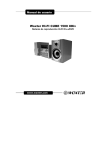
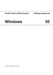
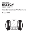
AZIMUTH. Azimuth Client – User Manual. A comprehensive guide to using the Client. Adam Berry 9/13/2013 This Document is updated regularly. If you are to find any discrepancies or errors please contact Azimuth immediately. Azimuth Client – User Manual. Contents Connecting to the Server. ................................................................................................ 2 Your main viewer. ........................................................................................................ 5 Menu Options. ............................................................................................................ 6 The Man-Machine Interface. .............................................................................................. 10 Miscellaneous ........................................................................................................... 12 Azimuth Client. Page 1 Azimuth Client – User Manual. Connecting to the Server. The first process in getting the Client working properly is to connect it to a server, or multiple servers. In this section you will find details on how to program both ends, the server and the client. First you must set up the Server Machine (The main Azimuth NVR) by following Edit → Azimuth Server → for Azimuth Remote Client. A Small window will open where you simply set up the Machines ID, Server name, and port. Azimuth Client. Page 2 Azimuth Client – User Manual. Now you must return to the client software itself. In the Client follow File → System → Edit Azimuth Servers and a new window will appear. In the advanced tab you must change the Azimuth Port to the port number you set on the server Machine. Then go to the General Tab and input the Azimuth name exactly how it was on the Server Machine. Also enter the IP address of the Server system. (Please note this will need to be the remote IP address if the two systems are not on the same network). Ensure that it is ticked as Active and edit the color so that this Server is distinguishable between others on the system. Click OK, and the server should connect. Azimuth Client. Page 3 Azimuth Client – User Manual. Once you have added the server to the client it will appear in the tree below with either a Green plus or a Red minus. These represent a correct or faulty connection to the server machine, and assuming that this has worked correctly you will be able to select the arrow to the left of the server and view a list of the Cameras available. Azimuth Client. Page 4 Azimuth Client – User Manual. Your main viewer. Your main Azimuth Client viewer window will now look like this, upon completion of the setup process. Now you know that you have a functioning connection to one or more server machines, you can begin to setup your screen how would like for it to appear. Want to see more than 4 screens?...... Click here to select 9, or 16 window viewing. On the left you will see a list of the server machines available, and clicking each one will reveal a list of the cameras available. If you wish to add a camera to one of the viewing windows, simply highlight the window of choice, and then double click that particular camera in the list on the left. On the right of option icons, running along the top of the window, ensure that the “Edit Screen Layout” (Shown as a pencil) option is selected whilst you are making changes to your screen layout. This tells Azimuth Client that you wish for the changes you are making to be permanent. Once complete, click the Edit Screen Layout button once more and the system will memorise your changes so that next time you open the application it will refer to the same screen layout. Azimuth Client. Page 5 Azimuth Client – User Manual. Menu Options. In the following pages we will look in detail at the 6 menu options you see at the top of the Client window. File: Access Login: This is where you can login into your client software. Depending on the user level you have set your cameras, your login may not be permitted to view them. Logout from Access Mode: If you have set user levels on your cameras to ensure those without permission do not view them, then logging out is important, to hide your cameras from others. Hide Desktop: Azimuth Client can be transparent, and therefore show main desktop image. If you wish to hide this so that when selected the client sits above everything else, then simply hide desktop. Select Azimuth Servers: This allows you to select or deselect which of your servers you wish to make visible. Simply double click to toggle from selected to deselected. Force Config Update: If you have made a change to the client, you can force the config update to inform the server. If not selected, it is an automatic process periodically. Keypad: Hold F1 and select a camera number to bring the image up on the Client. This require camera numbering. Show Keypad: Physically shows keypad in lower left screen to achieve same result. Admin Login: The main administrator login that allows changes to be made to all settings. Azimuth Client. Page 6 Azimuth Client – User Manual. Installer [Admin]: In this sub menu you have a number of options available. The first is event/recording management. This feature is normally setup on the Server machine, but it available to edit on the client should you decide that the recording parameters on your server are not correct and you have no direct access to your server machine. For more details on Event/Recording Management please refer to page 23 onwards of the Azimuth Server manual. Select Logo allows you to change the logos in the corner of the camera windows, as well as the background (desktop) image. Privileges allows you to define what each user level, of the 5 available, can do. Tree Access refers to the list of cameras available, whereas Server Select determines whether that user can select each server for use. User Always on means that even with access mode logged out, the camera streams will still be visible. MPEG4/H264 Streaming should be activated when you are aware that you have cameras that support MPGE4 or H264. This will be shown on in the MMI. SIP Configuration is for linking an SIP or VOIP module to the client. The purpose is to allow calls to and from a security guard or similar in the case of an emergency. The parameters in the SIP Setup should be made available by the SIP provider. Log defines how long the system saves logs for in the Bin folder. This is normally left as default. System: Another small sub-menu. The first is Connection, that allows you to Start or Stop each camera connection. This may be to refresh settings, or to make a fresh connection to the camera after a network error. Edit Azimuth Servers is where server connections are setup and edited. Details of this are defined on the opening pages of this document. Alarm Timeout defines how long an alarm alert remains unanswered before it is escalated to an ARC. An example of this is its use as something called a Dead Mans Handle. In this instance, an alarm is triggered and has to be acknowledged on the client by a security guard. If, after the time period defined here, it is not acknowledged, it can be passed on to an Alarm Receiving Centre as the operator may have been attacked. Azimuth Client. Page 7 Azimuth Client – User Manual. Edit: Remote Viewer: This option shall remain greyed out, regardless of your access rights, unless the Edit Screen Layout button (Pencil icon) is selected. It Simply allow you to add or delete a viewer panel. Minimize Resources: High, Medium, or Low define the quality and frame-rate of your live streams. The option to change these is made available so as to limit the PCU usage of your machine whilst continuing to record at a separate frame rate. None –Azimuth sets the frame rate the same as the server. Enable Fisheye Dewarp: Works only with Fish-Eye lens cameras. Takes the imagine and dewarps it to create a normal camera viewer. Set Control Monitor: This is only a necessary option when more than one monitor is connected. It simply asks which monitor to make the main. Hide Control Bar: Hides all icon options at the top of the screen. Hide Viewer Logo: Hides the logo from the upper right corner of the viewer screens. Joystick: When a joystick is detected its available buttons can be defined and tested here. Password: Here you define the passwords for each of the 5 different user levels. Left blank as default. Azimuth Client. Page 8 Azimuth Client – User Manual. View: Lock PTZ Controls: This is to lock all PTZ controls so that it is not possible to mistakenly knock a camera out of position with the joystick or similar. Reset MMI to centre Monitor – Moves MMI back to main screen. Tree View: Hides or enables the tree view of servers and cameras on the left. Map Viewer: Enables or disables Map Viewer for selected servers. SIP View: Opens up SIP (VOIP) Module for communcations. Tile: Allows you to tile image windows for tidying up screen. Window: The Window menu simply provides a secondary method for selecting a camera you wish to view. Operator: ACK RemoteAlarm: Certain cameras can be set so that when they go into an alarm state they must be Acknowldged by an operator or security guard in order to ensure the alarm has been recognised. If this is not done within a defined time period an alarm can be passed to an ARC. This one of three methods of ACKing an alarm, the others being to press F8, and to click ACK Alarm as it arrises in the lower corner. RemoteAlarms: If Selected turns on the RemoteAlarms that need to be acknowledged. Help: This final menu option simply indicates what version of the software you are operating. Azimuth Client. Page 9 Azimuth Client – User Manual. The Man-Machine Interface. The “Man-Machine Interface” built into the Azimuth software is the gateway to many of the features on Azimuth and many of the individual settings for each of the cameras. It is also where an operator can source any recorded images and scan through footage recorded by the camera. In order to open the Man-Machine Interface, simply highlight the camera required so that the window turns green, and click on the Azimuth logo in the top right hand corner of the window, bring up the window as shown at right. At the top you will see two options, Camera and Events. For details on how to alter the events setting please consult the Azimuth Server manual. Under the Camera tab can be found the same details that were set when the camera was initially installed. Here you can change details for the individual camera such as IP addresses, user-names and passwords as well as frame rate and resolution settings. The two small icons in the top left corner are for the camera controls and a drop down box which enables you to start recording and how you'd like to record, as well as add or remove certain elements such as camera controls from the live view. If the Man-Machine interface PTZ (Pan Tilt Zoom) controls in the top right corner are shown as locked, simply head to View → Lock All Camera Controls which should be ticked and this will free up the PTZ Capability in the Live view. If the camera you are viewing is not a PTZ camera these controls will not show up at all. The name of the Camera you are currently viewing can be seen along the top, with a small drop down box to its right. When dropped down it allows you to select a different camera without completely closing down the interface and having to highlight a new camera and start from scratch. In the top right-hand corner can be seen two small icons, of which one should already be selected. If you hover over these two Icons you will see that the one currently selected is for Live viewing, and you will at that point be looking at a live image stream from the camera. The 2nd Icon will take you through to any recorded images. Upon clicking this the window will increase in size and a date option will appear. You have three search options to choose from. The first is to select a day of the current week on the left hand side. If you are on Monday and you click Monday you will not get footage from the previous Monday. Once you have selected the day, click the Blue icon to the right. You can also click the green Icon which will take you to the most recent recordings for that camera. The final Option is to click on the calendar on the right and select a specific date followed by clicking the Clock Icon to the right. Upon selection of either one of the above three options the window will again increase in size until the section pictured below becomes visible. What you will at first notice is a time line with blue bars showing how much recording was captured and when. If this entire Bar is red it means that the camera has no recordings and you may wish to check your event settings. By hovering the mouse over each of the Icons and small tab will appear telling you what that Icons purpose is. By clicking on any one of the blue bars you should see an image appear in the window above, this is a sequence of images captured at the point from which the blue bar you select begins. For example on the image below by clicking in the longest blue bar, the first image will be at 14:00 as this is when that time section begins. By selecting the first Icon on the left hand side of the window you can chose to see only the Alarm images as opposed to a combination of alarm and timed images. The Purple Icon below that increases the size of the time bar allowing you to focus on much smaller time scale recordings. Below the time bar is a is series of Icons that run from left to right: Audio: If this is an enabled feature, you can select to have audio recordings turned on or off. Azimuth Client. Page 10 Azimuth Client – User Manual. Play: This will play in real time the recordings from the bar you have selected. (You can increase the frame rate using the drop down box to its right). Previous Block: This will take you back to the beginning of the previous 5 minute block. Previous Frame: Will take you back to the previous image to the one you're currently viewing. This allows you to filter back frame by frame to find exactly what it is you're looking for. Next Frame: Will take you to the next individual image, again allowing you to filter through each image one by one. Next Block: Will take you to the next 5 minute block. Add Current Image to Save List: This will add the image that is currently visible to the list of images/footage you wish to save. Add block to save list: This will add the entire block to the list of images/footage you wish to save. Add time block to save list: To the left of this icon is an option to input a precise time. With this done you can click that time block Icon and it will add those exact times to the list. Delete Selected Files: Any files in the list below that are ticked will be deleted. Save Selected files: Any files in the list below that are ticked will be saved. To the right of the Save list are two more options, these are simply so that you can either select or unselect all of the items in the list. Now that you have all the evidence in the save list, click on the green Icon on the right and again the window will increase in size as shown below. Simply select how you would like the Items to be saved. By selecting “Select” this will allow you to choose a location with the PC you are using to save the footage. Azimuth Client. Page 11 Azimuth Client – User Manual. Now click on “Start Save” after which another window will open. Here it will ask you which format you would like to the footage saved as and then you will be asked whether or not you wish for the footage to be saved into one folder or for the three different blocks to be saved to their own individual folders. At the following window you can select whether or not to have the time and date shown as a timestamp on the image and where, and can also select the frame rate that the footage plays at. 1 per second means you will literally only see one frame per second. The more higher the frame rate, the faster it will play. Now you will be asked where you want the footage to be saved followed by a progress bar as the footage is saved. Then it is complete, and you will be able to view your saved footage. Miscellaneous The Control bar shown above has a number of Icons. From Left to right: Shutdown Azimuth RemoteViewer. – This function only works for shutting down the system if embedded. Login – A simple login shortcut. Once the button is clicked it will ask you for your user level and password. Logout – Will log you out of your user level. Main Selection – Brings up a small switcher window allowing you to cycle through the main streams. Show Map – Must be setup on the server (See Azimuth Server Manual) and will show precise camera locations. 4, 9, 16 window options – Each one will change the layout of the screen with the required number of live stream windows. Default Layout – If you alter the position of any window, and then click this, it will return them to a default, tiled position. Edit Screen Layout – If you select this, alter screen positions and then de-select, it will save those screen positions. Below the Control Icons are 4 “LEDs” that might flash occasionally. From left to right they represent: Sending Control Command – Application is sending a control command to a camera. Access Mode – A user is currently logged on to access mode. Updating – Updating Database and Logs. Left to right: Toggle Servers – Allows you to turn server connections on or off. Show Map – Must be setup on the server (See Azimuth Server Manual) and will show precise camera locations. SIP Module – Brings up the SIP or VOIP Ip Communications module. Precise time. Number of Cameras accumulatively across servers & PCU Usage. Azimuth Client. Page 12 Azimuth Client – User Manual. The live camera windows also have options in each corner, some represented as drop down boxes and others as LEDs. On the far left is an arrow that will drop down some options, as follows: Clear Window – This will not close the window down, only remove the current camera from the frame to be replaced by another. Stop Camera – This will stop the camera feed and be replaced by the option to “Start Camera”. You may wish to do this to refresh the connection after a network error or force through changes in the settings that may have occurred. Size – “Image” will make the window and the camera stream the resolution that the camera is sending out. Fixed size will make the imagine fit to the screen layout you have chosen. Edit fixed size allows you to alter the resolution of the live window, and Image Zoom allows you to zoom in and increase or decrease the image size by percentages. Dewarp/Fixed – The Tool-bar shows/hides the digital zoom buttons in bottom left corner. Display Source toggles between showing original image and the de-warped or zoomed fixed image in the camera window. Reset/Home sets the current de-warp/zoomed image to the home position which is usually the centre of the main image. For de-warp the zoom may also reset. Edit – This allows you to edit camera details. It is not recommended that this is done on the client and if possible it should be done on the server but should it be it be necessary to do so on the client it is possible here, but will need full Administrator login. Advanced – Diagnostics simply provides a check on the cameras full connection. To the right of this drop down menu is a small icon resembling a graph, this is a simple way of viewing the recording Recording Stats. Next is a small button for enabling or disabling Digital PTZ. Finally, there is a maximum of 4 LEDs that may become visible depending on settings. From left to right they represent: Camera Streaming Azimuth Client. Camera Recording RemoteClient Alarms Current Image up to date. Page 13