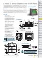
1
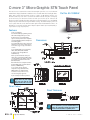
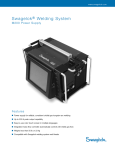
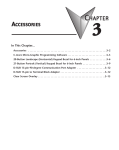
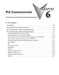
C-more 3” Micro-Graphic STN Touch Panel
This Touch Screen version of the C-more Micro-Graphic panel has a 3.1-inch STN LCD
monochrome display. Model EA1-S3ML has five selectable LED-driven backlight colors:
Green, Red, Amber, Yellow and Lime. It features a 128 x 64 dot display, and five userdefined function keys each with a user-defined red LED indicator. The panel can display
up to 10 lines by 32 characters of static text and up to 10 lines by 21 characters of
dynamic text with embedded variables and phrases mixed with graphics. It is rated NEMA
4/4X, IP-65 (when mounted correctly, for indoor use only). This Micro-Graphic panel can
receive power from the serial communications port of most AutomationDirect PLCs. An
EA-MG-SP1 Serial Port with DC Power Adapter option module (RS-232/422/485) is
required when using 3rd party PLCs.
Part No. EA1-S3ML
DL05/06
PLC
DL105
PLC
DL205
PLC
DL305
PLC
DL405
PLC
Features
• Touch screen display
• Free downloadable programming software
• 128 x 64 Dot display with up to 10 lines
by 32 characters of text and graphics
• Up to 10 lines by 21 characters of dynamic
text with embedded variables and phrases
mixed with graphics
• 5 programmable function keys can change
with every screen. Can increment / decrement values, trigger recipes, view index of
screens.
• 5-Color LED backlight for longer lifetime;
Green, Red, Amber, Yellow and Lime
• 2 optional snap-on keypad bezels
• 768 KB memory
• Panel is powered from PLC comm port
when using select AutomationDirect PLCs.
Use optional DC power adapter and serial
port modules if needed for other PLC’s
(RS-232/422/485)
• Built in Alarm Control setup that activates
beep, backlight flash, customized alarm
banner, and LED blinking
• 0 to 50 °C (32 to 122 °F) operating
temperature range (IEC 60068-2-14)
• NEMA 4/4X, IP-65 compliant when
mounted correctly, indoor use only
• UL, cUL & CE agency approvals
• 2-year warranty from date of purchase
PLC
Overview
Field I/O
<--->
C
UL
R
Software
C-more
HMIs
US
Dimensions
Other HMI
AC Drives
Motors
Steppers/
Servos
Motor
Controls
Proximity
Sensors
Photo
Sensors
Limit
Switches
Encoders
Current
Sensors
Pushbuttons/
Lights
NOTE: Don’t forget the optional
keypad bezels, DC power adapter
and serial port with DC power
adapter shown in the accessories.
Process
Relays/
Timers
Panel Cutout
Comm.
Panel Thickness
TB’s &
Wiring
Power
Circuit
Protection
Enclosures
NOTE: The C-more 3” Micro-Graphic cutout dimensions
are not equivalent to previous AutomationDirect text
panels. The C-more Micro-Graphic panels will not fit in
cutouts for DV-1000, EZText or Optimate panels.
Appendix
Part Index
w w w. a u to m a t i o n d i re c t . c o m / C - m o re - m i c ro
Operator Interface
B10–11
C-more 3” Micro-Graphic STN Touch Panel
This Touch Screen version of the C-more Micro-Graphic panel has a 3.1-inch STN LCD
monochrome display. Model EA1-S3MLW has five selectable LED-driven backlight colors:
White, Pink1, Pink2, Pink3 and Red. It features a 128 x 64 dot display, and five userdefined function keys each with a user-defined red LED indicator. The panel can display
up to 10 lines by 32 characters of static text and up to 10 lines by 21 characters of
dynamic text with embedded variables and phrases mixed with graphics. It is rated NEMA
4/4X, IP-65 (when mounted correctly, for indoor use only). This Micro-Graphic panel can
receive power from the serial communications port of most AutomationDirect PLCs. An
EA-MG-SP1 Serial Port with DC Power Adapter option module (RS-232/422/485) is
required when using 3rd party PLCs.
Part No. EA1-S3MLW
Features
• Touch screen display
• Free downloadable programming software
• 128 x 64 Dot display with up to 10 lines
by 32 characters of text and graphics
• Up to 10 lines by 21 characters of dynamic
text with embedded variables and phrases
mixed with graphics
• 5 programmable function keys can change
with every screen. Can increment / decrement values, trigger recipes, view index of
screens.
• 5-Color LED backlight for longer lifetime;
White, Pink1, Pink2, Pink3 and Red
• 2 optional snap-on keypad bezels
• 768 KB memory
• Panel is powered from PLC comm port
when using select AutomationDirect PLCs.
Use optional DC power adapter and serial
port modules if needed for other PLC’s
(RS-232/422/485)
• Built in Alarm Control setup that activates
beep, backlight flash, customized alarm
banner, and LED blinking
• 0 to 50 °C (32 to 122 °F) operating
temperature range (IEC 60068-2-14)
• NEMA 4/4X, IP-65 compliant when
mounted correctly, indoor use only
• UL, cUL & CE agency approvals
• 2-year warranty from date of purchase
<--->
C
UL
R
US
Dimensions
NOTE: Don’t forget the optional
keypad bezels, DC power adapter
and serial port with DC power
adapter shown in the accessories.
Panel Cutout
Panel Thickness
NOTE: The C-more 3” Micro-Graphic cutout dimensions
are not equivalent to previous AutomationDirect text
panels. The C-more Micro-Graphic panels will not fit in
cutouts for DV-1000, EZText or Optimate panels.
B10–12
Operator Interface
1 - 80 0 - 633 - 0405
C-more 3” Micro-Graphic Specifications
Model
Specification
Part Number
Description
Display
• Type
• Resolution
• Color
• Viewing Area Size
• Active Area Size
• Contrast
PLC
Overview
3” STN Micro-Graphic Panel
Touch Screen
3” STN Micro-Graphic Panel
Non-Touch Screen
EA1-S3ML, EA1-S3MLW
EA1-S3ML-N, EA1-S3MLW-N
DL105
PLC
128 x 64 dots LCD display, five user defined keypad function buttons, and five user defined LED's
DL205
PLC
3.1" STN monochrome LCD, graphical characters
DL305
PLC
128 (W) x 64 (H) dots
2 colors (normal / inverse)
DL405
PLC
2.789” (W) x 1.385” (H) [70.8 mm x 35.2 mm]
Field I/O
2.670” (W) x 1.259” (H) [67.8 mm x 32.0 mm]
Adjusted from the panel’s built-in configuration setup menu
• Viewing Angle
3, 9 o’clock axis –> 45 degrees
6 o’clock axis –> 45 degrees
12 o’clock axis –> 30 degrees
Software
LED
Other HMI
C-more
HMIs
Backlight
• Type
• Color
• User Replaceable
Touch Screen
• Type
• Operation
• Life
Features
• User Memory
• Number of Screens
• Beep (Internal)
• Keypad Function
Buttons
• Keypad Function
Button LEDs
• Serial Communications
• Expansion Connection
5 user defined colors: EA1-S3ML, EA1-S3ML-N - Red, Green, Amber, Lime, and Yellow
EA1-S3MLW, EA1-S3MLW-N - White, Pink1, Pink2, Pink3 and Red
AC Drives
No
Motors
Analog touch panel
N/A
51 gram force [0.5 N] maximum
N/A
Minimum of 1,000,000 cycles
N/A
Steppers/
Servos
Motor
Controls
768 KB
Proximity
Sensors
Up to 999 – limited by project memory usage
Photo
Sensors
Yes
Five user defined function key buttons with the ability to customize the label.
Minimum of 500,000 cycles
Limit
Switches
Each function key button includes a red LED that can be user programmed.
Encoders
Built-in RJ12 serial communications port (RS-232).
Optional serial communications port (RS-232, RS-485/422) when using the optional EA-MG-SP1 Serial Port with DC Power Adapter.
Current
Sensors
Yes – used with optional Keypad Bezels, EA-MG-BZ1 & BZ2, and EA-MG-P1 DC Power Adapter,
and EA-MG-SP1 Serial Port with DC Power Adapter.
Screen Objects
• Functional Devices
DL05/06
PLC
Push Button, Switch, Indicator Button, Indicator Light, Graphic Indicator Light, Numeric Display, Numeric Entry, Inc/Dec Value, Bar Graph,
Bitmap Button, Static Bitmap, Dynamic Bitmap, Recipe Button, Static Text, Lookup Text, Dynamic Text, Scroll Text,
Screen Change Push Button, Screen Selector, Adjust Contrast, Function, Key Configuration Object, Realtime Graph, Line Graph, Analog Meter
• Static Shapes
• Displayable Fonts
Pushbuttons/
Lights
Process
Lines, Rectangles, Circles and Frames
Relays/
Timers
Fixed fonts: 6x6, 6x8, 8x16, 16x16, 32x16, 32x32 / Windows fonts
C-more 3” Micro-Graphic panel specifications continued on next page.
Comm.
TB’s &
Wiring
Power
Circuit
Protection
Enclosures
Appendix
NOTE: Photo includes EA-MG-BZ2
Part Index
w w w. a u to m a t i o n d i re c t . c o m / C - m o re - m i c ro
Operator Interface
B10–15
C-more 3” Micro-Graphic Specifications
Model
Specification
Part Number
Electrical
• Input Voltage Range
• Input Power
3” STN Micro-Graphic Panel
Touch Screen
3” STN Micro-Graphic Panel
Non-Touch Screen
EA1-S3ML, EA1-S3MLW
EA1-S3ML-N, EA1-S3MLW-N
5.0 VDC (4.75 – 5.25 VDC)
Supplied through the panel’s RJ12 serial communications port connection when used with any AutomationDirect PLC having an RJ12
communication port. Can also be supplied from an external 12-24 VDC power source when using the optional EA-MG-P1 DC Power Adapter,
or the optional EA-MG-SP1 Serial Port with DC Power Adapter
• Power Consumption
1.05 W @ 5 VDC (210 mA)
• Recommended Fuse
Type AGC fast acting glass fuse, 250 mA, 250 VAC, ADC p/n AGC-25
No fuse required when directly connected to a PLC or PC with recommended cable.
• Maximum Inrush
Current
• Acceptable External
Power Drop Duration
Environmental
• Operating Temperature
• Storage Temperature
• Humidity
• Environmental Air
• Vibration
• Shock
• Noise Immunity
• Enclosure
• Agency Approvals
1 A for 500 µs
Maximum 1 ms
0 to 50 °C (32 to 122 °F)
–20 to +60 °C (–4 to +140 °F)
5–95% RH (non-condensing)
No corrosive gases permitted
IEC60068-2-6 (Test Fc), 5-9 Hz: 3.5 mm amplitude, 9-150 Hz: 1.0G, sweeping, at a rate of 1 octave/min. (±10%),
10 sweep cycles per axis on each of 3 mutually perpendicular axes
IEC60068-2-27 (Test Ea), 15 G peak, 11 ms duration, three shocks in each direction per axis,
on 3 mutually perpendicular axes (total of 18 shocks)
NEMA ICS3-304
RFI, (145 MHz, 440 Mhz 10 W @ 10 cm)
Impulse 1000 V @ 1 µs pulse
NEMA 4/4X, IP-65 (When mounted correctly, for indoor use only.)
CE (EN61131-2), UL508, CUL Canadian C22.2 No. 142-M95, UL File E157382
Physical
• Dimensions
• Enclosure Mounting
Thickness Range
• Mounting Clip Screw
Torque Range
• Depth from bezel rear
with options Module
• Weight
4.488” (W) x 3.228” (H) x 1.593” (D) [114.0 mm x 82.0 mm x 40.5 mm]
0.04” – 0.2” [1 – 5 mm]
21 – 28 oz-in [0.15 – 0.2 Nm]
2.295” [58.3 mm]
5.82 oz. (165 g)
NOTE: The environmental specifications for the panels shown
above are also applicable for the C-more Micro-Graphic
accessories shown later in this section of the catalog.
NOTE: Photo includes EA-MG-BZ2
B10–16
Operator Interface
1 - 80 0 - 633 - 0405
C-more 6” Micro-Graphic Panel Accessories
PLC
Overview
DL05/06
PLC
D-SUB 15-pin 90-degree Communication Port Adapter
The EA-ADPTR-4 adapter plugs into the 15-pin serial port on the rear of the 6” panel to allow a PLC communication cable to
be plugged in at a 90 degree angle to reduce panel depth requirements. 15-pin straight through pin-out. UL Recognized.
Dimensions
Part No.
EA-ADPTR-4
DL105
PLC
DL205
PLC
DL305
PLC
0.333
[8.5]
Units: inches [mm]
DL405
PLC
Field I/O
1.605
[40.8]
Date code
Country of Origin
Software
KOYO ELECTRONICS INDUSTRIES CO., LTD.
EA-ADPTR-4
IOIOI – PLC
1.873
[47.6]
C-more
HMIs
0.793
[20.2]
Other HMI
R
AC Drives
<--->
Motors
0.751
[19.1]
Steppers/
Servos
Motor
Controls
Proximity
Sensors
D-SUB 15-pin to Terminal Block Adapter
Photo
Sensors
The EA-COMCON-3 adapter plugs into the 15-pin serial port on the rear of the 6” panel to allow wire
terminal connections for an RS-422/RS-485/DH-485 PLC communication cable. UL Recognized.
Limit
Switches
Dimensions
Part No.
EA-COMCON-3
Encoders
0.687
[17.5]
Units: inches [mm]
Current
Sensors
Pushbuttons/
Lights
Process
1.756
[44.6]
Date code
Country of Origin
Relays/
Timers
RD+
RD–
SD+
SD–
GND
EA-COMCON-3
TERM
KOYO ELECTRONICS INDUSTRIES CO., LTD.
Comm.
R
1.873
[47.6]
1.126
[28.6]
TB’s &
Wiring
Power
<--->
Circuit
Protection
0.903
[22.9]
TERM
RD+
RD–
SD+
SD–
GND
Terminals
Enclosures
Appendix
Part Index
w w w. a u to m a t i o n d i re c t . c o m / C - m o re - m i c ro
Operator Interface
B10–47
C-more 6” Micro-Graphic Panel Accessories
Clear Screen Overlay
Optional clear screen overlay used to protect C-more 6” Micro-Graphic displays from minor scratches and
wear. Package contains 3 clear screen overlays.
Part No. EA-6-COV2
Dimensions
0.197
[5.0]
4.913
[124.8]
EA-6-COV2
0.157
[4.0]
3.795
[96.4]
<--->
Clear Screen Overlay Installation
Step 2
Step 1
Remove the overlay from the
package
Remove the paper backing
from the overlay
Step 4
Step 3
Align the overlay with the screen
and press the adhesive firmly
into place
Remove the protective film*
*Note: The overlay cover ships with a thin protective film on the
face that should be carefully removed after installation.
B10–48
Operator Interface
1 - 80 0 - 633 - 0405
C-more 3” Micro-Graphic PLC Connections
Cabling requirements
Micro-Graphic Port 1 to CLICK PLC Port 2
When using the built-in RJ12 serial port on the C-more
Micro-Graphic panel to connect with the CLICK, DL05,
DL06, DL105, DL205, D3-350 and DL405 CPUs, your
cabling choices are fairly simple.
• DV-1000CBL — connects to CLICK, DL05, DL06, DL105, DL205,
D3-350 and D4-450 phone jack.
• D4-1000CBL — connects to all DL405 CPU 15-pin ports.
CLICK PLC
Port 1
A maximum cable length of 10 feet between the
C-more Micro-Graphic panel and the PLC is recommended
when powering the panel from the PLC.
The Serial Port with DC Power Adapter module,
EA-MG-SP1, can be used if the application requires the use
of RS-422 or RS-485. The serial port on the adapter,
designated as port 2, can also be wired for RS-232. The
use of the adapter permits greater cable length distances.
See the PLC Communication Protocols & Cabling Charts in
this catalog section for details on the selection of various
PLCs, protocols, and connectivity.
C-more 3 Inch
Micro-Graphic
Panel
Port 2
DV-1000CBL
serial cable
Micro-Graphic Port 1 to DL06 PLC Port 1
C-more
Micro-Graphic
Panel
PLC Supported Protocols
• AutomationDirect CLICK (Modbus)
• DirectLOGIC K-sequence
• DirectNET
• Modbus (Koyo Addressing)
• Modbus RTU
• Entivity Modbus RTU
• Allen-Bradley DF1 Half Duplex
• Allen-Bradley DF1 Full Duplex
• Allen-Bradley PLC5 DF1
• Allen-Bradley DH485
• GE Fanuc SNPX (90/30, 90/70, Micro 90, VersaMax Micro)
• Omron Host Link (C200 Adapter, C500)
• Omron FINS Serial (CJ1, CS1)
• Mitsubishi Melsec FX
• Mitsubishi Q and QnA
• Siemens PPI
DL-06
PLC
Port
1
Port
1
Direct LOGIC
serial cable
p/n DV-1000CBL
Micro-Graphic Port 1 to DL205 PLC Port 1
DL-205 PLC
Direct LOGIC
serial cable
p/n DV-1000CBL
Micro-Graphic Port 2 to DL06 PLC Port 2
Port 1
Serial Port w/
DC Power Adapter
EA-MG-SP1
Port 1
C-more
Micro-Graphic
Panel
DL-06
PLC
Port
2
C-more to
Direct LOGIC
VGA 15-pin port
serial cable
p/n EA-2CBL-1
B10–18
Operator Interface
Port
2
C-more
Micro-Graphic
Panel
1 - 80 0 - 633 - 0405
C-more 3” Micro-Graphic PLC Communication
Protocols & Cabling Chart
PLC Compatibility & Connection Chart
PLC
DL205
PLC
Panel to PLC Cabling Components Required for Specific Port and Protocol being used.
Family
CLICK
CPU
Port &
Type
Powered from an external 24 VDC
source using the DC Power
Adapter, EA-MG-P1.
Using panel’s RJ12 port 1
Using panel’s RJ12 port 1
Using panel’s RJ12 port 1
Protocol(s)
Components &
Supported
Network Type
Automation
DV-1000CBL
Direct Modbus
RS-232
(CLICK)
K-sequence,
Direct NET,
Modbus RTU
Direct LOGIC
Port 1
RJ12 - 6 pin K-sequence,
DL05
Direct NET,
all versions
Port 2
RJ12 - 6 pin
Port 1
RJ12 - 6 pin
all versions
Port 2
DB15HD
(female)
Serial Port with DC Power Adapter
Powered with 5 VDC from the
connected PLC’s comm. port.
Protocol(s)
Components &
Supported
Network Type
Automation
DV-1000CBL
Port 1
all versions
Direct Modbus
RS-232
RJ12 - 6 pin
(CLICK)
(see D0-DCM
under DL06)
DC Power Adapter
Modbus RTU
DV-1000CBL
RS-232
DV-1000CBL
RS-232
K-sequence,
Direct NET,
Modbus RTU
DV-1000CBL
+ FA-15HD
RS-232
DV-1000CBL
RS-232
Powered from an external 24 VDC source using the Serial Port
with DC Power Adapter, EA-MG-SP1.
DV-1000CBL
+ FA-15HD
RS-232
DL405
PLC
Protocol(s)
Components &
Supported
Network Type
Automation
DV-1000CBL
Direct Modbus
RS-232
(CLICK)
K-sequence,
Direct NET,
Modbus RTU
K-sequence,
Direct NET,
Modbus RTU
C-more
HMIs
DV-1000CBL
RS-232
DV-1000CBL
RS-232
K-sequence,
Direct NET,
Modbus RTU
DV-1000CBL
+ FA-15HD
RS-232
K-sequence,
Direct NET,
Modbus RTU
Modbus RTU
Direct LOGIC
DL06
DV-1000CBL
RS-232
Port 1
RJ12 - 6 pin
D0-DCM
Port 2
DB15HD
(female)
K-sequence,
Direct NET,
Modbus RTU
DV-1000CBL
+ FA-15HD
RS-232
DV-1000CBL
RS-232
K-sequence,
Direct NET,
Modbus RTU
DV-1000CBL
+ FA-15HD
RS-232
DV-1000CBL
RS-232
K-sequence,
Direct NET,
Modbus RTU
DV-1000CBL
+ FA-15HD
RS-232
K-sequence,
Direct NET,
Modbus RTU
Modbus RTU
Direct LOGIC all versions
Port 1
RJ12 - 6 pin
DL105
D2-230
D2-240
D2-250-1
Direct LOGIC
DL205
Port 1
RJ12 - 6 pin
Port 1
RJ12 - 6 pin
Port 2
RJ12 - 6 pin
Port 1
RJ12 - 6 pin
Port 2
DB15HD
(female)
K-sequence
DV-1000CBL
RS-232
K-sequence
DV-1000CBL
RS-232
K-sequence
K-sequence,
Direct NET
Port 2
DB15HD
(female)
DV-1000CBL
RS-232
K-sequence
DV-1000CBL
RS-232
K-sequence
DV-1000CBL
RS-232
K-sequence,
Direct NET
DV-1000CBL
RS-232
K-sequence,
Direct NET,
Modbus RTU
DV-1000CBL
+ FA-15HD
RS-232
K-sequence,
Direct NET,
Modbus RTU
DV-1000CBL
+ FA-15HD
RS-232
DV-1000CBL
RS-232
K-sequence
DV-1000CBL
RS-232
K-sequence
DV-1000CBL
RS-232
K-sequence
K-sequence,
Direct NET
DV-1000CBL
RS-232
K-sequence,
Direct NET,
Modbus RTU
DV-1000CBL
RS-232
Port 1
RJ12 - 6 pin
D2-260
K-sequence
DV-1000CBL
+ FA-15HD
RS-232
DV-1000CBL
+ FA-15HD
RS-232
DV-1000CBL
RS-232
K-sequence,
Direct NET,
Modbus RTU
DV-1000CBL
+ FA-15HD
RS-232
DV-1000CBL
RS-232
K-sequence,
Direct NET,
Modbus RTU
EA-2CBL
RS-232
EA-2CBL
RS-232
EA-2CBL-1
RS-232
See Note
RS-422
See Note
RS-485
Modbus only
EA-2CBL
RS-232
EA-2CBL-1
RS-232
See Note
RS-422
See Note
RS-485
Modbus only
K-sequence
EA-2CBL
RS-232
K-sequence
EA-2CBL
RS-232
K-sequence
K-sequence,
Direct NET
DV-1000CBL
RS-232
DV-1000CBL
RS-232
K-sequence,
Direct NET,
Modbus RTU
DL305
PLC
Using adapter’s serial Port 2
15-pin D-sub - female
Protocol(s)
Components &
Supported
Network Type
Automation
EA-2CBL
Direct Modbus
RS-232
(CLICK)
DV-1000CBL
RS-232
K-sequence,
Direct NET,
Modbus RTU
DL05/06
PLC
DL105
PLC
C-more Micro-Graphic Panel
PLC Port Powered
PLC
Overview
EA-2CBL
RS-232
EA-2CBL
RS-232
K-sequence,
Direct NET,
Modbus RTU
EA-2CBL-1
RS-232
See Note
RS-422
K-sequence,
Direct NET,
Modbus RTU
DV-1000CBL
+ FA-15HD
RS-232
Modbus RTU
D2-DCM
Port 1
DB 25 pin
(female)
K-sequence,
Direct NET,
Modbus RTU
See Note
RS-232
K-sequence,
Direct NET,
Modbus RTU
See Note
RS-232
K-sequence,
Direct NET,
Modbus RTU
See Note
RS-232
Direct NET
WINPLC
Port 1
RJ12 - 6 pin
Modbus RTU
DV-1000CBL
RS-232
Modbus RTU
DV-1000CBL
RS-232
Modbus RTU
DV-1000CBL
RS-232
Modbus RTU
EA-2CBL
RS-232
EA-2CBL-1
RS-232
See Note
RS-422
See Note
RS-485
Modbus only
EA-4CBL-2
RS-232
See Note
RS-422
EA-2CBL
RS-232
Field I/O
Software
Other HMI
AC Drives
Motors
Steppers/
Servos
Motor
Controls
Proximity
Sensors
Photo
Sensors
Limit
Switches
Encoders
Current
Sensors
Pushbuttons/
Lights
Process
Relays/
Timers
Comm.
TB’s &
Wiring
Power
Circuit
Protection
Enclosures
Appendix
Note: See the C-more Micro-Graphic Hardware User Manual, Chapter 6: PLC Communications, for wiring diagrams that the user can use to construct
their own cables. Available for download at www.automationdirect.com. PLC Compatibility & Connection Chart continued on next page.
Part Index
w w w. a u to m a t i o n d i re c t . c o m / C - m o re - m i c ro
Operator Interface
B10–19
C-more 3” Micro-Graphic PLC Communication
Protocols & Cabling Chart (cont’d)
PLC Compatibility & Connection Chart
PLC
C-more Micro-Graphic Panel
Panel to PLC Cabling Components Required for Specific Port and Protocol being used.
PLC Port Powered
Family
CPU
Port &
Type
Powered from an external 24 VDC
source using the DC Power
Adapter, EA-MG-P1.
Using panel’s RJ12 port 1
Using panel’s RJ12 port 1
Protocol(s)
Supported
D3-232-DCU
DB 25 pin
(female)
D3-330 or
D3-340 D3-422-DCU
DB 25 pin
(female)
Port 1
RJ11 - 4 pin
DC Power Adapter
Powered with 5 VDC from the
connected PLC’s comm. port.
Components &
Network Type
Not Possible
Not Possible
Not Possible
Direct LOGIC
DL305
Port 1
RJ12 - 6 pin
D3-350
Port 2
DB 25 pin
(female)
Not Possible
K-sequence,
Direct NET
DV-1000CBL
RS-232
Not Possible
Using panel’s RJ12 port 1
Protocol(s)
Supported
Components &
Network Type
Protocol(s)
Supported
Components &
Network Type
Direct NET
See Note
RS-232
Direct NET
EA-4CBL-2
RS-232
Not Possible
Direct NET
D3-340
Port 2
RJ11 - 4 pin
Serial Port with DC Power Adapter
Powered from an external 24 VDC source using the Serial Port
with DC Power Adapter, EA-MG-SP1.
Direct NET,
Modbus RTU
Not Possible
Direct NET
OP-3CBL-1
RS-232
Direct NET,
Modbus RTU
Using adapter’s serial Port 2
15-pin D-sub - female
Protocol(s)
Components &
Supported
Network Type
Direct NET
EA-4CBL-2
RS-232
Direct NET
See Note
RS-422
Direct NET
OP-3CBL-1
RS-232
Direct NET,
Modbus RTU
K-sequence,
Direct NET
DV-1000CBL
RS-232
K-sequence,
Direct NET
DV-1000CBL
RS-232
K-sequence,
Direct NET
K-sequence,
Direct NET,
Modbus RTU
See Note
RS-232
K-sequence,
Direct NET,
Modbus RTU
See Note
RS-232
K-sequence,
Direct NET,
Modbus RTU
EA-3CBL
RS-232
EA-2CBL
RS-232
EA-4CBL-2
RS-232
See Note
RS-422
EA-4CBL-2
RS-232
See Note
RS-422
Port 1
D3-DCM
D3-350 only DB 25 pin
(female)
K-sequence,
Direct NET,
Modbus RTU
See Note
RS-232
K-sequence,
Direct NET,
Modbus RTU
See Note
RS-232
K-sequence,
Direct NET,
Modbus RTU
See Note
RS-232
Direct NET
Port 0
DB 15 pin
(female)
K-sequence
D4-1000CBL
or DV-1000CBL
& FA-CABKIT
RS-232
K-sequence
D4-1000CBL
or DV-1000CBL
& FA-CABKIT
RS-232
K-sequence
D4-1000CBL
or DV-1000CBL
& FA-CABKIT
RS-232
K-sequence
EA-4CBL-1
RS-232
K-sequence,
Direct NET
DV-1000CBL
& FA-CABKIT
RS-232
K-sequence,
Direct NET
DV-1000CBL
& FA-CABKIT
RS-232
K-sequence,
Direct NET
EA-4CBL-2
RS-232
See Note
RS-422
K-sequence
D4-1000CBL
or DV-1000CBL
& FA-CABKIT
RS-232
K-sequence
D4-1000CBL
or DV-1000CBL
& FA-CABKIT
RS-232
K-sequence
EA-4CBL-1
RS-232
K-sequence,
Direct NET
DV-1000CBL
& FA-CABKIT
RS-232
K-sequence,
Direct NET
DV-1000CBL
& FA-CABKIT
RS-232
K-sequence,
Direct NET
EA-4CBL-2
RS-232
See Note
RS-422
K-sequence
D4-1000CBL
or DV-1000CBL
& FA-CABKIT
RS-232
K-sequence
D4-1000CBL
or DV-1000CBL
& FA-CABKIT
RS-232
K-sequence
EA-4CBL-1
RS-232
K-sequence,
Direct NET,
Modbus RTU
DV-1000CBL
& FA-CABKIT
RS-232
K-sequence,
Direct NET,
Modbus RTU
DV-1000CBL
& FA-CABKIT
RS-232
K-sequence,
Direct NET,
Modbus RTU
EA-4CBL-2
RS-232
See Note
RS-422
K-sequence,
Direct NET,
Modbus RTU
See Note
RS-422
D4-430
Port 1
DB 25 pin
(female)
Port 0
DB 15 pin
(female)
Not Possible
K-sequence
D4-440
Port 1
DB 25 pin
(female)
Direct LOGIC
DL405
Port 0
DB 15 pin
(female)
D4-450
D4-DCM
D4-1000CBL
or DV-1000CBL
& FA-CABKIT
RS-232
Not Possible
K-sequence
D4-1000CBL
or DV-1000CBL
& FA-CABKIT
RS-232
Port 1
DB 25 pin
(female)
Not Possible
Port 3
DB 25 pin
(female)
Not Possible
Not Possible
Not Possible
Port 2
RJ12 - 6 pin
K-sequence,
Direct NET
DV-1000CBL
RS-232
K-sequence,
Direct NET
DV-1000CBL
RS-232
K-sequence,
Direct NET
DV-1000CBL
RS-232
K-sequence,
Direct NET
EA-2CBL
RS-232
Port 1
DB 25 pin
(female)
K-sequence,
Direct NET,
Modbus RTU
See Note
RS-232
K-sequence,
Direct NET,
Modbus RTU
See Note
RS-232
K-sequence,
Direct NET,
Modbus RTU
See Note
RS-232
Direct NET
EA-4CBL-2
RS-232
See Note
RS-422
Note: See the C-more Micro-Graphic Hardware User Manual, Chapter 6: PLC Communications, for wiring diagrams that the user can use to construct
their own cables. Available for download at www.automationdirect.com. PLC Compatibility & Connection Chart continued on next page.
B10–20
Operator Interface
1 - 80 0 - 633 - 0405
C-more 3” Micro-Graphic PLC Communication
Protocols & Cabling Chart (cont’d)
C-more Micro-Graphic Panel
DL205
PLC
Panel to PLC Cabling Components Required for Specific Port and Protocol being used.
PLC Port Powered
Family
CPU
Port &
Type
DC Power Adapter
Powered with 5 VDC from the Powered from an external 24 VDC
source using the DC Power
connected PLC’s comm. port.
Adapter, EA-MG-P1.
Using panel’s RJ12 port 1
Protocol(s)
Supported
Components &
Network Type
Using panel’s RJ12 port 1
Protocol(s)
Supported
Components &
Network Type
Serial Port with DC Power Adapter
Powered from an external 24 VDC source using the Serial Port
with DC Power Adapter, EA-MG-SP1.
Using panel’s RJ12 port 1
Protocol(s)
Supported
Components &
Network Type
Using adapter’s serial Port 2
15-pin D-sub - female
Protocol(s)
Components &
Supported
Network Type
DF1 Full Duplex EA-MLOGIX-CBL
DF1 Half Duplex
RS-232
8-pin
Allen-Bradley 1000, 1100, mini-din port
MicroLogix 1200, 1500 RJ45 8-pin
DH485/AIC/AIC+
phone plug
EA-DH485-CBL
RS-232
DF1 Full Duplex EA-SLC-232-CBL
DF1 Half Duplex
RS-232
5/03, 5/04,
9-pin
5/03
phone plug
DH485/AIC/AIC+
Allen-Bradley
ControlLogix
all
9-pin
D-sub port
DF1 Full Duplex EA-SLC-232-CBL
DF1 Half Duplex
RS-232
Allen-Bradley
CompactLogix
all
9-pin
D-sub port
DF1 Full Duplex EA-SLC-232-CBL
DF1 Half Duplex
RS-232
Allen-Bradley
FlexLogix
all
9-pin
D-sub port
DF1 Full Duplex EA-SLC-232-CBL
DF1 Half Duplex
RS-232
25-pin
D-sub port
DF1 Full Duplex
5/05
D-sub port
Allen-Bradley
SLC500
5/01, 5/02, RJ45 8-pin
Allen-Bradley
PLC5
RJ45 8-pin
phone plug
Micro 90,
VersaMax
Micro
Melsec
FX Series
Mitsubishi
DH485/AIC/AIC+
RJ45
Port 1
15-pin
D-sub port
Port 2
SNPX
Not Possible
Not Possible
Not Possible
25-pin
D-sub port
CPU Direct
8-pin
mini-din port
9-pin
D-sub port
Q / QnA
Q / QnA
6-pin
mini-din port
Omron
Modicon
Siemens
EA-DH485-CBL
RS-232
DL305
PLC
DL405
PLC
Field I/O
Software
C-more
HMIs
Other HMI
AC Drives
Motors
Steppers/
Servos
Motor
Controls
EA-PLC5--232-CBL
Proximity
RS-232
Sensors
all
15-pin
90/30, 90/70 D-sub
port
GE
DL05/06
PLC
DL105
PLC
PLC Compatibility & Connection Chart
PLC
PLC
Overview
EA-DH485-CBL
RS-232
EA-90-30-CBL
RS-422
See Note
RS-232
Photo
Sensors
Limit
Switches
EA-90-30-CBL
RS-422
Encoders
EA-MITSU-CBL
RS-422
Current
Sensors
EA-MITSU-CBL-1
RS-422
Pushbuttons/
Lights
See Note
RS-232
Process
See Note
RS-232
Relays/
Timers
Comm.
C200
(Adapter),
C500
25-pin
D-sub port
Host Link
EA-OMRON-CBL
RS-232
CJ1, CS1,
CQM1,
CPM1,
CPM2,
C200
9-pin
D-sub port
FINS
See Note
RS-232
984 CPU,
Quantum
113 CPU,
AEG
Modicon
Micro Series
110 CPU
varies
S7-200
CPU
9-pin
D-sub port
0 or 1
TB’s &
Wiring
Power
Modbus RTU
See Note
RS-232
Circuit
Protection
Enclosures
PPI
See Note
RS-485
Appendix
Note: See the C-more Micro-Graphic Hardware User Manual, Chapter 6: PLC Communications, for wiring diagrams that the user can use to construct Part Index
their own cables. Available for download at www.automationdirect.com. Available cables with descriptions shown on the next page.
w w w. a u to m a t i o n d i re c t . c o m / C - m o re - m i c ro
Operator Interface
B10–21