1
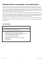
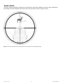
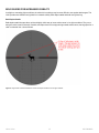
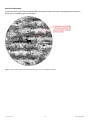
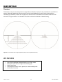
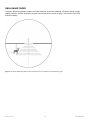
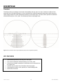
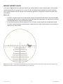
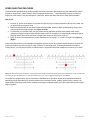
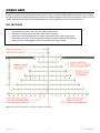
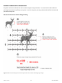
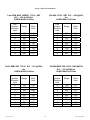
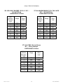
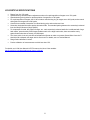
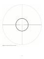
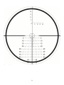
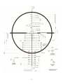
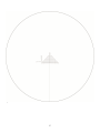
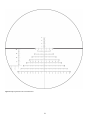
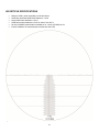
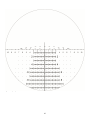
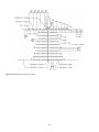
Horus Vision HUNTER Model 2500 series User’s Manual 1st Edition January 2014 January 12, 2014. Copyright 2014 Horus Vision, LLC. All rights reserved. Patent pending. Written consent of Horus Vision LLC is required to copy or use any of the material in this manual. Horus Vision 1 650‐588‐8862 CONTENTS Introduction ........................................................................................................................................................................... 3 About Horus Vision .................................................................................................................................................... 3 Safety Warning ........................................................................................................................................................... 3 Getting Started ...................................................................................................................................................................... 4 Mounting Your Horus™ Scope .................................................................................................................................. 4 Elevation and Windage Turrets .................................................................................................................................. 5 Zeroing Your Horus Scope......................................................................................................................................... 6 Slipping the Dials to Zero ........................................................................................................................................... 7 Introduction to Hunter™ Riflescope ................................................................................................................................... 8 H130™ Reticle ....................................................................................................................................................................... 9 Speed Shooting Features ........................................................................................................................................ 10 Rage Finder ............................................................................................................................................................. 11 Bold Guides for Increased Visibility ......................................................................................................................... 13 H425™ Reticle ..................................................................................................................................................................... 15 Range Finder ........................................................................................................................................................... 16 Bold Duplex Stadia Lines ......................................................................................................................................... 17 H59™ Reticle ....................................................................................................................................................................... 19 Moving Target Holds ................................................................................................................................................ 20 Speed Shooting Features ........................................................................................................................................ 21 Horus Grid............................................................................................................................................................................ 22 Vertical and Horizontal Adjustments ........................................................................................................................ 23 Second Shot Correction ........................................................................................................................................... 24 Range Finding with the Horus Grid .......................................................................................................................... 25 Range / Data Cards ............................................................................................................................................................. 26 Additional Information ........................................................................................................................................................ 30 Technical Data ..................................................................................................................................................................... 31 Hunter Scope Specifications .................................................................................................................................... 31 H130 Reticle Specifications ..................................................................................................................................... 32 H425 Reticle Specifications ..................................................................................................................................... 36 H59 Reticle Specifications ....................................................................................................................................... 41 General Care ........................................................................................................................................................................ 44 Warranty ............................................................................................................................................................................... 45 Legal Notice ......................................................................................................................................................................... 46 Contact ................................................................................................................................................................................. 47 Horus Vision 2 650‐588‐8862 INTRODUCTION ABOUT HORUS VISION Horus Vision’s cutting-edge technology improves shooting accuracy at extended ranges and increases the likelihood of a first-round hit. Our patented reticles reduce the need for manual scope manipulation and mental calculation. Horus Vision’s simplified shooting system improves accuracy at any distance and can make anyone an expert marksman. Horus Vision’s ATrag™ ballistics software algorithms were developed and refined by the former chief of ARDEC's small-arms division, William C. Davis. Horus Vision was founded in 2000 and is headquartered in San Bruno, California. SAFETY WARNING Always use great care with all firearms. A mistake in judgment or lapse of attention can result in serious injury or death. The information in this manual, while believed to be accurate at the date of publication, is not warranted or represented to be accurate, correct, or useful for any particular purpose. Use the information in this manual with caution and common sense, and verify it with respect to your own firearms before use. The author and publishing company accept no responsibility for errors in the information presented herein, or for accidents, injuries, damage or any other problems which might arise as a result of your use of the information contained in this book, and expressly disclaim all liability for injuries, death and damages, whether direct, incidental, consequential, punitive or otherwise. Horus Vision 3 650‐588‐8862 GETTING STARTED MOUNTING YOUR HORUS SCOPE The Hunter requires 30mm rings, which are available in steel and aluminum. Steel rings offer enhanced durability under extreme conditions, but they also weigh more. Rings are generally available in four different heights: low, medium, high and extra high. The choice depends upon your rifle’s configuration and your normal body position on the rifle. Rings may come attached to a one-piece base or as separate units. Separate bases or other “riser” type mounting systems may also be used for raising scope height. 1. Mount the bottom portion of the rings to the rifle’s mounting rail, making sure that the spacing is correct so the rings won’t interfere with the scope’s turrets. 2. Place the scope on the bottom portion of the rings, positioning it far enough rearward to provide a clear field of view (FOV). 3. Attach the top portion of the ring, tightening the screws enough to prevent the scope from falling out of the mounts, but loose enough to enable you to adjust the scope forward and aft and to rotate the scope to ensure a level reticle. 4. Focus the ocular by adjusting the rear-most ring on the eyepiece. The reticle should be crisp against a distant object or bright surface. The diopter is adjustable to +/- -2, +1 so the scope can be used with or without corrective lenses. 5. To establish proper eye relief, hold your rifle in a stable shooting position and close your eyes. Position the rifle into your shoulder as if firing, and then open your eyes. If the eye relief position is correct, you shouldn’t see any black or hazy outer ring (vignette effect) within the FOV. If the image is not complete or clear, lower the rifle and gently slide the scope forward or aft in the rings, and then repeat the above exercise. It helps to have someone move the scope while you maintain position. Continue this procedure until the image is correctly viewed through the eyepiece when you open your eyes. Once you’re satisfied that the scope is properly aligned on the rifle, repeat this exercise four or five times in quick succession to ensure that your positioning is correct. If you intend to fire from alternate positions regularly, check eye relief in those positions as well, since they’ll change the relationships between shoulder, head and arms. Set up your eye relief for whatever body position you will most likely use the majority of the time. 6. Before tightening the top portion of the rings, place a spirit level on the elevation turret to check level against the rifle’s receiver. If the rifle has a Picatinny top rail on the receiver, use that surface as the index to level the scope off of. If no rail is available, use the best horizontal surface you can find, such as the bottom metal portion of a bolt action with the floor plate open or magazine removed. While leveling the reticle by eye will work at close ranges, minor level errors will affect use of reticle grid and knob adjustments at farther targets. 7. When satisfied with eye relief and reticle level, tighten the scope ring screws to 15-20 inch-pounds of pressure. Warning: Over-tightening can damage the scope tube. Horus Vision 4 650‐588‐8862 ELEVATION AND WINDAGE TURRETS Your Horus scope is designed to allow all elevation and windage adjustments to be made within the reticle, as opposed to the conventional method of dialing target knobs or ballistic drop compensating (BDC) knobs. However, your Horus scope also has knobs for elevation and windage adjustments with audible clicks, eliminating the need to take your eyes off the target. Rotate clockwise for up/right adjustment. 1. Unscrew and remove the knob cap by turning it counter-clockwise in relation to the scope’s body. 2. Use the elevation knob on top of the scope to make adjustments for bullet drop compensation. Rotate the elevation knob clockwise to move the intended point of impact (POI) up in the field of view, rotate counterclockwise to move the intended point of impact (POI) down in the field of view. Use the windage knob on the right side of the scope to make adjustments for wind compensation. Rotate the windage knob clockwise to move the intended POI right in the field of view, and rotate clockwise to move the POI left. Each increment (or click) equates to a 0.1 mil change to the bullet impact point, and 10 clicks is equal to 1 mil. 3. When finished making adjustments, return the knob cap to the knob and secure by turning it clockwise. Figure 1: Rotating the elevation turret clockwise will move the POI up in the field of view (top). Rotating the windage turret clockwise will move the POI right in the field of view (bottom). Horus Vision 5 650‐588‐8862 ZEROING YOUR HORUS SCOPE While Horus scopes can be zeroed at any distance, it is recommended that the zero be exactly 100 meters or yards. Regardless of zero range, it is critical that the measurement be precise. The following recommended method of zeroing will eliminate problems while saving time and ammunition: 1. Measure the distance from the rifle to the target to ensure a precise “zero” measurement. 2. Use an 18x18-inch (or larger) sheet of paper with ½-inch vertical and horizontal lines drawn to intersect at the center of the paper. Use a plumb or level to attach the paper to a target backer so that the lines are level. 3. Set your scope power ring to maximum power (21x), and make sure the elevation and windage turrets are set to 0. 4. Superimpose the Horus reticle over the vertical and horizontal lines on your target to center the reticle precisely on your intended point of impact (POI). 5. Fire your first shot. Adjust the elevation and windage turrets to center the shot at the intersection of the vertical and horizontal lines on the target. If the round’s POI is observable, use the Horus reticle’s mil-based grid to measure the deviation from the intended POI, and then dial the exact corrections (in 0.1 mil increments) using the elevation and windage turrets. For example, if your first shot impacts 2 mils low and 1.5 mils right, dial 2 mils (20 clicks) up and 1.5 mils (15 clicks) left (see the previous section for information about rotating the turrets). 6. Center the reticle over your intended POI and fire another round. Repeat steps 5 and 6 until repeated shots are successfully centered at the intersection of the target’s vertical and horizontal lines. 7. Fire a five round group at a clean target. Adjust zero as needed and confirm with additional groups until it perfectly matches your intended POI. 8. Lock the elevation and windage turrets into place by pushing them in toward the center of the scope. From this point on, use only the gridlines on the Horus reticle—not the turrets—to make adjustments for wind and elevation. Remember to always verify your zero and develop data with the ammunition that you intend to use for any sport shooting or hunting purpose. Horus Vision 6 650‐588‐8862 SLIPPING THE DIALS TO ZERO Your Horus scope is designed to allow all deviations from zero for windage and elevation to be made within the reticle, as opposed to the conventional method of dialing windage and elevation turrets. You may elect to index the turrets on “0” once the rifle is zeroed to allow a return point for zero in the event you adjust the turrets for any reason. To set the dials to zero in this manner: 1. 2. 3. 4. Remove the turret cap by unscrewing. Next, loosen the turret bolt on top of the turret using a coin, such as a dime. Once the turret bolt is loose or removed, carefully pull the turret from its base. Rotate it until the “0” mark indexes on the thin white line, and push the turret back down into place. Take care not to inadvertently turn the turret while performing this procedure, as it will alter the scope’s zero point. Once the turret has been set to “0”, reinstall and tighten the bolt. Always verify zero after resetting the dials. Important: Do not attempt to loosen the screws beneath the turret bolts of the windage and elevation turrets, as these are only to be removed by a Horus Vision authorized warranty station. Figure 2: Slipping the elevation and adjustment turrets to “0” will provide a definitive index point to return to in the event you ever adjust them off zero. Horus Vision 7 650‐588‐8862 INTRODUCTION TO THE HUNTER 3-12x50 RIFLE SCOPE The Hunter rifle scope is easy to use and understand. Many hunters have rifles capable of making solid hits out to 600 yards. Yet they only take shots at 100 yards or less. Why? Because their scope has no simple way to accurately know where to hold or how many come-up clicks to put into the elevation knob. The Hunter presents a simple solution: match the Horus Grid line numbers to your ballistic data. Clicking elevation and windage knobs is no longer necessary. You don't have to "bracket" for atmospheric changes, turn knobs or count clicks. To make things as easy as possible, we’ve done the ballistics math for you by developing range (data) cards for the most popular hunting cartridges. In most cases, the range cards provided will work very well for your hunting experiences. As you become more proficient with your Hunter’s patented reticle, you may wish to use Horus’ ATragMX ballistics software to calculate your own range cards, tailored to your rifle, ammo, and environmental conditions. The Hunter is your ticket to versatility. This is not a ballistic reticle that locks you into a single rifle or load. You don't have to dedicate this scope to a single rifle. The Hunter will work on any rifle. In fact, you no longer need a separate scope for each rifle you own. KEY FEATURES 3-12x50mm Choice of non-illuminated reticle: H59, H425, H130 Equally effective on any rifle, cartridge, ammo, caliber Precise holdover for wind and drop without manually adjusting knobs Reticle grid enables rapid Second Shot Correction™ Taller turret assembly for ease of dialing Approximately 10% more in field of view Wider Power selector for ease of cycling thru magnification Fixed parallax Includes sunshade Horus Vision 8 650‐588‐8862 H130 RETICLE Overview The H130 hunting reticle offers easy-to-use speed-shooing features for making rapid adjustments for wind and elevation. A bold outer ghost ring and bold duplex lines along the reticle's main horizontal stadia provide increased visibility in low and contrasting light conditions. The range finder and entire reticle are calibrated in inches for easy calculations in units familiar to hunters. Figure 3: The H130 reticle shown at high magnification (LEFT) and low magnification (RIGHT). KEY FEATURES Horus Grid for traditional mil-based shooting out to 700+ meters Easy-to-use speed shooting features for wind and elevation adjustments Bold duplex stadia lines for twilight and contrasting light Bold ghost rings for increased visibility in brush cover or contrasting light Range finder calibrated in inches Entire reticle calibrated in inches Compensate for elevation, wind, spindrift, etc. without dialing knobs Second Shot Correction Horus Vision 9 650‐588‐8862 SPEED SHOOTING FEATURES The H130 contains several different speed-shooting features to assist with rapid acquisition of targets. Central Aiming Ring Near reticle center is a central aiming ring for targets out to 200 yards. Central Aiming Block Near reticle center is a central aiming block for targets out to 300 yards. Elevation Adjustment Diamonds Diamond-shaped markers along the reticle’s main vertical stadia provide holds for making lightning-fast elevation adjustments for targets out to 700 yards. Wind Guides Dashed angled lines provide wind guides for targets out to 800 yards. LEARN MORE For more information about the H130 reticle, view the H130 manual in PDF format on the Horus Vision website: http://horusvision.com/download/manual_Horus_hunter.pdf. Horus Vision 10 650‐588‐8862 RANGE FINDER To assist in determining distance to target, the H130 features a range finder calibrated in inches for easy calculations in units familiar to hunters. Alternately, the H130’s Horus Grid can also be used for ranging in inches. Figure 4: The H130’s range finder is shown positioned in front of a target to assist in determining range. Horus Vision 11 650‐588‐8862 How to Use Range Finder Figure 5: The H130’s range finder being used to determine range. A deer’s standard chest height of 24” is shown to measure 6 units tall. The target’s real world height (24”) and image height (6) are plugged into the standard formula for range, determining range to be 400 yards. Horus Vision 12 650‐588‐8862 BOLD GUIDES FOR INCREASED VISIBILITY In twilight or contrasting light conditions, the reticle’s thin markings may become difficult to see against dark targets. The H130 provides two different bold guides for increased visibility: bold duplex stadia and bold outer ghost ring. Bold Duplex Stadia Bold duplex stadia lines provide a quick and highly visible way to locate reticle center in low light conditions. They occur along the reticle’s main horizontal crosshair, and taper down to fine tips pointing towards reticle center, leaving space for a clear uncluttered view. Use as follows. Figure 6: Target shown centered between the H130’s bold duplex stadia lines in low light conditions. Horus Vision 13 650‐588‐8862 Bold Outer Ghost Ring A bold outer ghost ring provides increased visibility, allowing the reticle to be used for rapid targeting at low power in brush cover or contrasting light. Use as follows. Figure 7: Target shown centered in the H130’s bold outer ghost ring in contrasting light conditions. Horus Vision 14 650‐588‐8862 H425 RETICLE Overview The H425 is an easy-to-use hunting reticle. Its range finder is calibrated in inches for easy calculations in units familiar to hunters. Bold duplex stadia lines along the reticle’s main horizontal stadia allow for easy viewing under twilight or contrasting light conditions, at either low or high power, when thinner lines are harder to see and more difficult to work with under low light conditions. The Standard Horus Grid is included for traditional mil-based shooting. Figure 8: The H425 reticle shown at high magnification (LEFT) and low magnification (RIGHT). KEY FEATURES Horus Grid for traditional mil-based shooting out to 700+ meters Bold duplex stadia lines for twilight and contrasting light SMOA range finder Compensate for elevation, wind, spindrift, etc. without dialing knobs Second Shot Correction Horus Vision 15 650‐588‐8862 SMOA RANGE FINDER To assist in determining distance to target, the H425 features a range finder calibrated in Shooter’s Minute of Angle (SMOA), familiar to hunters. Alternately, the H425’s Horus Grid can be used for ranging in mils (see the Horus Grid manual for details). Figure 9: The H425’s SMOA range finder is shown positioned in front of a target to assist in determining range. Horus Vision 16 650‐588‐8862 How to Use SMOA Range Finder Figure 10: The H425’s range finder being used to determine range. A deer’s standard chest height of 24” is shown to measure 6 units tall. The target’s real world height (24”) and image height (6) are plugged into the standard formula for range, determining range to be 400 yards. Horus Vision 17 650‐588‐8862 BOLD DUPLEX STADIA LINES In twilight or contrasting light conditions, the reticle’s thin markings may become difficult to see against dark targets. The H425’s bold duplex stadia lines provide a quick and highly visible way to locate reticle center in low light conditions. They occur along the reticle’s main horizontal crosshair, and taper down to fine tips pointing towards reticle center, leaving space for a clear uncluttered view. How to Use Center target in the gap between the bold duplex stadia lines when fine reticle markings are hard to see due to low or contrasting light conditions. Figure 11: Target shown centered between the H425’s bold duplex stadia lines in low light conditions. Horus Vision 18 650‐588‐8862 H59 RETICLE Overview The H59 provides more windage and elevation hold capability than any optic in its class. Unobtrusive Holdover Dots extend the Horus Grid while allowing for a clear uncluttered view. Advanced speed-shooting markers allow shooters to rapidly engage targets out to 600 yards without needing to know target range. The Horus Grid is provided for traditional mil-based shooting out to 700+ yards. The H59 also provides moving-target holds. Figure 12: The H59 reticle shown at high magnification (LEFT) and low magnification (RIGHT). KEY FEATURES Speed-shooting features for shooting out to 600 yards Horus Grid for traditional mil-based shooting out to 700+ yards Central dot at crosshair intersection for refined aim and un-obscured view for a tighter zero Holdover dots to extend Horus Grid without obscuring targets Compensate for elevation, wind, spindrift, etc. without dialing knobs Second Shot Correction Horus Vision 19 650‐588‐8862 MOVING TARGETS HOLDS You’ll notice in Figure 13 that the H59 has a series of even numbers above the main horizontal stadia. These numbers represent speeds for moving targets at 2, 4, 6, 8 and 10 mph, with additional holds starting at 20 mils and continuing every 10 mph thereafter to the left and right. These speeds are optimized for .308 caliber, but may be used with many other calibers. How to use: To hold on a target moving at one of these speeds, position the target behind the portion of the horizontal stadia that intersects with the short line nearest the number representing the target speed. You may need to account for possible adjustments for ranges different from optimal. If using the Horus grid for elevation adjustment, use a hold point vertically aligned with the appropriate speed. To hold on a target traveling at a speed between markings (such as 5 mph), hold between the even numbers on either side of it (4 and 6 mph). st Figure 13: The Accuracy 1 Speed Shooting Formula allows use of the numbers along the horizontal stadia to rapidly acquire moving targets. This example shows a hold for a target running at approximately 8 mph, from right to left. Horus Vision 20 650‐588‐8862 SPEED SHOOTING FEATURES The H59 includes speed-shooting guides to rapidly determine an elevation hold without using the traditional mil relation formula for range-finding. These markers, which incorporate the Accuracy 1st Speed Shooting Formula, work well for targets out to 600 meters. They are arranged in a “stair step” pattern just above the reticle’s main horizontal stadia. How to Use: 1. Locate a 12” portion of the target, such as the area from the top of a target’s shoulder to the top of the head. Any 12” object near the target will work. 2. Placing the target’s base on the reticle’s main horizontal stadia, determine which speed-shooting marker most closely matches the target’s height. See Figure 14 (Left). 3. To determine your elevation hold, note the number directly below the speed-shooting marker most closely matching the target’s height, and divide that number in half. For example, if the target height matches the speedshooting marker above the 6 mph Moving Target Hold, divide 6 in half to get a value of 3. 4. Place the 3-mil horizontal stadia line (usually expressed as “3 mils high” or “+3 mils”) on target. See Figure 14 (Right). This process works well for many cartridges and weapon systems, but not all will impact exactly the same. However this system should place you close enough to make a solid hit, all else being equal. If shooting with a different caliber or muzzle velocity, you may need to add to or subtract from the original elevation hold to adapt the formula for your needs. Figures 14: The reticle image at left depicts a 12-inch target bracketed between the main horizontal stadia and the line above the “6 mph” moving target hold (LEFT). At right, after dividing the “6” in half, an elevation hold of “3” is used to engage the target’s center mass (RIGHT). For targets beyond 600 meters, the H59 includes the Standard Horus Grid which allows for the traditional methods of determining range and holdover for elevation based on the mil-relation formula, yielding great accuracy. However, the speed-shooting markers provide a faster method for shooting at moderate ranges (out to 600 yards/meters) with common weapon systems. Horus Vision 21 650‐588‐8862 HORUS GRID The Horus Grid is an evolutionary advancement in reticle design. It replaces outdated mildots with a purely visual method for making adjustments. Making adjustments takes mere seconds and happens while looking through the scope. All Horus reticles contain the Horus Grid, though implementation may vary in appearance from one reticle to the next. KEY FEATURES Compensate for elevation, wind, drift, etc. without dialing knobs Secondary horizontal lines to precisely compensate for elevation Hash marks along horizontal lines to precisely compensate for wind, drift, target speed… Second Shot Correction, a unique method for making a fail-safe hit after missed first shot Range finding, measure targets in mils to aid in determining range to target Figure 15: The H425’s implementation of the Horus Grid showing key markings. Horus Vision 22 650‐588‐8862 VERTICAL AND HORIZONTAL ADJUSTMENTS The Standard Horus Grid provides a purely visual system for placing adjustment holds, eliminating the need to dial mechanical knobs. Instead of turning knobs, the shooter visually repositions aim up and down, left or right, using the Horus Grid. It takes mere seconds and happens while looking through the scope, so your eye and mind stay focused on target. To place elevation adjustment holds, use the numbered secondary horizontal stadia lines spaced 1 mil apart. To place horizontal adjustment holds (wind, drift, target speed, etc.), use the vertical hash marks along the secondary horizontal stadia lines. With the H425 and H59, larger hash marks are spaced 1 mil apart, and smaller hash marks are spaced 0.2 mils apart. Example: 6-mil elevation adjustment, 3.8-mil left wind adjustment Figure 16: Vertical and horizontal adjustment holds are placed using the H425’s Horus Grid. The H425’s small hashes subtend to 0.2 mils. Horus Vision 23 650‐588‐8862 SECOND SHOT CORRECTION The Second Shot Correction™ method is a fail-safe technique for rapidly correcting aim after a missed first shot. This method is purely visual, requires no calculations or turning knobs, and is extremely fast. It’s unique to our patented reticle grid, so only Hours reticles have it. In the unlikely event of a missed first shot, note the point on the Horus Grid where the missed bullet struck. To make a bull’s-eye hit, simply reposition that point directly over your target, and shoot. Be sure to repeat your first shot’s exact shooting position, sight picture, and trigger control. The only difference will be the point of targeting on the reticle. How to Use Figure 17: Second Shot Correction is depicted using the H425’s Horus Grid. Horus Vision 24 650‐588‐8862 RANGE FINDING WITH HORUS GRID Any portion of the Horus Grid can be used to measure targets for rage estimation. You must know the real-world size of your target for accurate range finding. If you guess or use the wrong size, your range determination will be inaccurate and your shot will likely miss. How to Use the Horus Grid for Range Finding Figure 18: H59’s Horus Grid being used to measure target’s size in mils to assist in determining range to target. Horus Vision 25 650‐588‐8862 RANGE / DATA CARDS To make using your Hunter scope as convenient as possible, this manual includes pre-calculated range / data cards for the most popular hunting cartridges. To place your hold, simply match the data card numbers to your Horus Grid numbers. For example, let’s assume you have a .270 Winchester hunting rifle and 140 gr Bear Claw ammo. Find the pre-calculated range / data card in this manual (page 23) that matches your weapon system. Cut that card out and attach it to your rifle stock. Be sure your rifle is zeroed at exactly 100 yards. Now match your data card’s numbers to your reticle’s Horus Grid numbers. For a target range of 670, Line Number Elevation Hold of 6, and Wind Hold of 2.8, you would position your target behind the 6-mil secondary stadia line and the 2.8-mil hash. See Figure 19. How to Use Our Data Cards with Your Hunter Scope Figure 19: H59 reticle being used with pre-calculated range card provided by Horus. Hold for 670 range shown on 6-mil secondary stadia line and 2.8mil hash. Horus Vision 26 650‐588‐8862 (range / data card examples) .243 WIN. 100 Gr. B.C. : .430 @ 2950 fps 10 MPH Wind Full Value Line Number Elevation Hold 0 1 2 3 4 5 6 7 8 Range Wind Hold 100 310 440 550 640 720 800 870 920 0.20 0.65 1.01 1.28 1.56 1.82 2.09 2.35 2.54 25/06 REM NOSLER 120 Gr. B.C. : .391 @ 2950 fps 10 MPH Wind Full Value Line Number Elevation Hold 0 1 2 3 4 5 6 7 8 6.5 REM MAG 140 Gr. SBT B.C. : .530 @ 2800 fps 10 MPH Wind Full Value Line Number Elevation Hold 0 1 2 3 4 5 6 7 8 Horus Vision Range Wind Hold 100 290 410 520 620 710 790 860 930 0.18 0.52 0.77 1.01 1.24 1.47 1.69 1.88 2.09 Range Wind Hold 100 300 420 520 610 690 760 820 880 0.22 0.70 1.04 1.34 1.66 1.95 2.22 2.47 2.73 .270 WIN 140 Gr. Bear Claw B.C. : .292 @ 2950 fps 10 MPH Wind Full Value Line Number Elevation Hold 0 1 2 3 4 5 6 7 8 27 Range Wind Hold 100 280 390 480 550 620 670 720 770 0.30 0.91 1.35 1.78 2.12 2.51 2.80 3.11 3.41 650‐588‐8862 (range / data card examples) .308 WIN 175 Gr. SBT B.C. : .496 @ 2610 fps 10 MPH Wind Full Value 7 mm REM MAG SIERRA 175 Gr. SBT B.C. : .533 @ 2800 fps 10 MPH Wind Full Value Line Number Elevation Hold 0 1 2 3 4 5 6 7 8 Range Wind Hold 100 300 440 550 650 750 830 900 980 0.17 0.51 0.79 1.01 1.23 1.49 1.70 1.90 2.11 Line Number Elevation Hold 0 1 2 3 4 5 6 7 8 30/06 REM SBT 175 Gr. B.C. : .501 @ 2800 fps 10 MPH Wind Full Value Line Number Elevation Hold 0 1 2 3 4 5 6 7 8 Horus Vision Range Wind Hold 100 280 410 520 610 700 770 850 910 0.19 0.53 0.82 1.07 1.30 1.56 1.76 2.00 2.19 Range Wind Hold 100 260 370 470 550 630 700 770 830 0.18 0.55 0.82 1.06 1.30 1.54 1.75 1.97 2.18 .300 WIN MAG FED 190 Gr. G.M. MATCH B.C. : .533 @ 2900 fps 10 MPH Wind Full Value Line Number Elevation Hold 0 1 2 3 4 5 6 7 8 28 Range Wind Hold 100 300 430 550 660 750 830 910 980 0.17 0.51 0.77 1.01 1.26 1.49 1.70 1.91 2.11 650‐588‐8862 (range / data card examples) .338 WIN MAG BARNES 250 Gr. X B.C. : .521 @ 2750 fps 10 MPH Wind Full Value Line Number Elevation Hold 0 1 2 3 4 5 6 7 8 Range Wind Hold 100 280 400 510 600 690 760 825 900 0.18 0.52 0.78 1.02 1.25 1.50 1.72 1.89 2.10 .375 H+H MAGNUM WIN 270 Gr. FAIL SAFE B.C. : .388 @ 2670 fps 10 MPH Wind Full Value Line Number Elevation Hold 0 1 2 3 4 5 6 7 8 Range Wind Hold 100 270 380 490 580 660 730 800 870 0.17 0.52 0.77 1.02 1.25 1.48 1.68 1.88 2.10 .375 H+H PMC 300 Gr. Barnes B.C. : .548 @ 2500 fps 10 MPH Wind Full Value Line Number Elevation Hold 0 1 2 3 4 5 6 7 Horus Vision Range Wind Hold 100 240 350 440 525 600 670 740 0.17 0.52 0.77 1.02 1.25 1.48 1.68 1.88 29 650‐588‐8862 ADDITIONAL INFORMATION Horus Vision scopes and reticles make the complex process of precision shooting faster and easier. From the point where you identify a target, to the point where you follow-through to confirm the hit, there are several critical steps where Horus technology makes a difference: 1. 2. 3. 4. Ranging Use of grid for holdover Wind holds and/or moving target lead lines Follow-through and Second Shot CorrectionTM You can explore these steps in greater detail in the Horus Vision Tactical Manual in PDF format on the Horus Vision website: http://horusvision.com/download/manual_Horus_Tactical.pdf. Please refer to it for proper application of these steps. Increase Accuracy with ATragMXTM Ballistics Software For even greater accuracy, Horus ATragMX Ballistics Software can be used in combination with your Horus scope and reticle. Our ballistics software lets you take combat-proven aiming solutions into the field so you are instantly ready for any shooting conditions. ATragMX enhances any mil-based reticle system, but it is not required. To learn more about the benefits of Horus Ballistics Software, see the ATrag User Manual in PDF format on the Horus Vision website: http://horusvision.com/download/manual_Horus_ATrag-v385.pdf. Horus Vision 30 650‐588‐8862 TECHNICAL DATA HUNTER SCOPE SPECIFICATIONS Figure 20: Hunter scope dimensions. Specifications: Power .................................. 3-12x Length ................................. 13.375” (35.5cm) Weight ................................. 24oz (690g) Tube Diameter..................... 30 mm Wall Thickness .................... 2 mm Material: .............................. aluminum A5056 Tube .................................... 1 piece Color .................................... black Exterior Finish ..................... matte anodized Shockproof .......................... 1200g Water-resistant .................... yes, nitrogen gas filled Dustproof ............................. yes Fogproof .............................. yes Warranty .............................. limited lifetime Twilight Factor ..................... 12.25 @ 3x / 24.5 @ 12x Reticle ................................. H130, H59 or H425 Reticles................................ 1st focal plane Reticle Illumination .............. no Lenses ................................. 12 + reticle Lens Coating ....................... fully multi-coated Objective Lens..................... 50 mm Horus Vision Field of View ........................437 to 116 inches (at 100y) (12.1 to 3.22 yards) (36’5” to 9’8”) Eye Relief.............................3.2" - 3.7" (81-94 mm) Exit Pupil ..............................16.7 – 4.2 mm Ocular Type .........................rapid European focus Diopter Adjustment ..............more than (-3,+3) Elevation Increment .............1 click = .10 mil radian Elevation Adj. Range ...........more than 32.8 mils (118 MOA) Windage Increments ............1 click = .10 mil radian Windage Adj. Range ............more than 33 mils (119 MOA) Turret Caps ..........................yes Turret Type ..........................medium height Power Selector Style ...........manual Parallax ................................fixed at 100 m Sun Shade ...........................3.125” (80 mm) (thread size: M52x0.75 mm) Optional Accessories ASLI Ocular (Eye) Lens Cap ........1.7” Objective Lens Cap..............2.2” 31 650‐588‐8862 H130 RETICLE SPECIFICATIONS Range: from 0 to 700 yards. Speed-shooting vertical-elevation-adjustment markers for rapid acquisition of targets out to 700 yards. Speed-shooting wind guides for rapid acquisition of targets out to 700 yards. For rapid acquisition of targets, the H130 includes a central aiming ring for targets out to 200 yards, and a central aiming block for targets out to 300 yards. Central dot at crosshair intersection for refined aiming point and un-obscured view. Secondary horizontal lines allow precise elevation holds. The standard spacing between the secondary horizontal lines is exactly 5 Minutes of Angle (MOA*). To compensate for wind, drift, speed of target, etc.: each secondary horizontal stadia line is calibrated with “large hash marks” spaced exactly 5 MOA apart; between each of the large hash marks, there are smaller evenly spaced hash marks that are exactly 2.5 MOA apart. The Horus reticle is the only reticle that facilitates the rifleman to make an accurate Second Shot Correction™ should he fail to dispatch the target with his first round. For details, see our Tactical Manual. Range finder calibrated in inches. Precise calibration of measurements to within less than 0.5%. For details, see H130 User Manual in PDF format on the Horus Vision website: http://horusvision.com/download/manual_horus_h130.pdf 32 Figure 21: Low magnification view of the H130 reticle. 33 Figure 22: High-magnification view of the H130 reticle. 34 Figure 23: The H130 reticle with specs. 35 H425 RETICLE SPECIFICATIONS Range: from 0 to 700 yards. Range finder calibrated in inches. Central targeting grid calibrated in USMC mils (6283 mils/circle) (1 mil = 3.60 inches at 100 yards) (10cm at 100 meters). Precise calibration of measurements to within less than 0.5%. Secondary horizontal lines allow precise elevation holds. The standard spacing between the secondary horizontal lines is exactly 1 mil. To compensate for wind, drift, speed of target, etc.: each secondary horizontal stadia line is calibrated with “large hash marks” spaced exactly 1 mil apart; between each of the large hash marks, there are smaller evenly spaced hash marks that are exactly 0.2 mils apart. 36 Figure 24: Full view of the H425 reticle. 37 Figure 25: High-magnification view of the H425 reticle. 38 Figure 26: The H425 reticle with specs in metric. 39 Figure 27: The H425 reticle with specs in mils. 40 H59 RETICLE SPECIFICATIONS Range to 2000+ yards, depending on rifle and ammo Secondary horizontal stadia lines subtend to 1.0 mil Large hash marks subtend to 1.0 mil Small hash marks subtend to 0.2 mil for ease of use at 21x 50 mils (169 MOA) total elevation available at 3x; 14 mils (47 MOA) at 12x Precise calibration of measurements to within less than 0.5% Figure 28: Full view of the H59 reticle. 41 Figure 29: High magnification view of the H59 reticle. 42 Figure 30: H59 reticle technical drawing with specs. 43 GENERAL CARE Your Horus scope requires very little maintenance. The following simple steps will ensure maximum optical performance: Wipe clean all exposed optical surfaces occasionally with the lens cloth provided. Maintain metal surfaces by removing any dirt, dust or sand with a soft brush to avoid scratching the finish; then wipe down with a damp cloth, followed by a dry cloth. For best luster and corrosion resistance, finish by wiping metal surfaces with a silicone cloth. Protect your scope with lens caps when not in use. 44 WARRANTY LIMITED LIFETIME WARRANTY This Horus Hunter Rifle Scope is warranted to be free of defects in material and workmanship for as long as it is owned by the original buyer. If at any time during the warranty period the product is found to have defects in materials or workmanship, Horus Vision, LLC, will, at its discretion, repair or replace it free of charge, when requested by the original buyer. All expenses related to replacing or repairing a defective scope or part under this warranty shall be assumed by Horus Vision, LLC, except for the cost of sending the Rifle Scope to Horus Vision, LLC, for which the buyer will be responsible. When returning the scope, the buyer should carefully pack the Horus Hunter Rifle Scope, preferably in the original box, including a copy of the original purchase receipt and a description of the problem, to Horus Vision, LLC. This warranty does not apply to any costs, repairs or services for the following: damage resulting from unauthorized repair or alteration; normal wear and tear; physical abuse; chipped paint or blemishes; broken lenses; or internal damage due to impact with a foreign object. This warranty gives you specific legal rights, and you may also have other rights which vary from state to state. You have the right to bring any action at law or equity to resolve disputes concerning or to enforce the provisions of this warranty. Limitation of Damages. In no event shall Horus Vision, LLC, be liable for consequential damages for breach of this warranty. Some states do not allow the exclusion or limitation of incidental or consequential damages, so the above limitation or exclusion may not apply. 45 LEGAL NOTICE HORUS VISION® and the EYE OF THE FALCON logo are registered trademarks of Horus Vision, LLC and may not be used in any manner without express permission from Horus Vision, LLC. SECOND SHOT, TACTICAL SOLUTIONS and TARGETING SOLUTIONS are trademarks of Horus Vision, LLC and may not be used in any manner without express permission from Horus Vision, LLC. Horus Vision software products and written and visual materials are protected by U.S. and international copyright protection and may not be used in any manner without express permission from Horus Vision, LLC. A wide variety of scopes, reticles, software, computer systems, and other products associated with shooting and ballistics (“Horus Vision systems”) are exclusively owned by Horus Vision, LLC and are protected by issued patents in the United States, including U.S. Pat. Nos. 5,920,995, 6,032,374, 6,453,595, 6,516,699 and 6,681,512, issued foreign counterparts, as well as numerous additional pending patent applications in the United States and foreign jurisdictions, including, but not limited to Europe, Japan, Israel, Canada and Australia. Manufacture, sale, importation or use of the Horus Vision systems requires a license from Horus Vision, LLC. For more specific information on obtaining a license, please contact Horus Vision, LLC. Nothing contained herein should be construed as granting, by implication, estoppels or otherwise, any license or right to use any Horus Vision, LLC intellectual property. © 2013 Horus Vision, LLC. All rights reserved. 46 CONTACT Horus Vision, LLC 598 San Mateo Avenue San Bruno, CA 94066 Phone: 650-588-8862 Fax: 650-588-6264 E-mail: [email protected] Website: www.horusvision.com 47


![model internals [how it works]](http://vs1.manualzilla.com/store/data/005954312_1-42c8e6865238cf1b0aa463440300c4fe-150x150.png)