1
SLM-600/700/900V( )
SLM-600/700/900 R( )
Operating / Installation Manual
S L M - 6 0 0 / 7 0 0 / 9 0 0 V(V e n t i l a t i n g T y p e)
S L M - 6 0 0 / 7 0 0 / 9 0 0 R(R e c y c l i n g T y p e)
Please read this manual carefully
before using this appliance.
Dear Customer:
Thank you for selecting this Fujioh product.
Please read this manual carefully before installing and operating this
appliance, and retain it for future reference.
Any malfunctions, accidents or damages occurring as a result of noncompliance with the content and precautions stated in this manual shall
not be covered by the company’s scope of warranty, and any related
liability will also not be borne by the manufacturer.
"|I
`bdfhjkmo。qr)^
Please retain all attached literature and your receipt for purchase of this
appliance for future reference.
Please note:
)^
"#
FUJIOH INTERNATIONAL TRADING PTE. LTD. reserves all rights to
the final interpretation of the content of this manual.
Please be aware that you will not be otherwise notified in the event of
any future amendments to the content.
d}。
s`bduvwxz{km。]
_]
]
UW,X$?"#12YZ@A,"#12[B\。
=。>?@ABCD2EFG"#H,+IJKNOPQ
$%&'()*+."#12,&458;<%
!
,。
Recommendation
If the cooker hood will not be used for an extended period
of time, please remove the plug from the socket.
obd58pqr
New cooker hood packaging
st。udvw,!xJyz{|。
Please dispose of the packaging materials in an environmentally
friendly manner to maintain our surroundings. Do not allow children
to play with the plastic film and packaging cartons as this may result
in suffocation. Keep all packaging materials out of children’s reach
and be aware that packaging materials are not toys.
Disposal of old cooker hoods
FUJIOH INTERNATIONAL TRADING PTE.LTD.*lmn
!;<:
!(]*^_`abcdea: fg,hij$。
JK&NO*PQT5,UWJXYBCZ[\B。
.1234&58:;<=>,?@ABCDE、=D:GHI
Old cooker hoods should be discarded once they can no longer be
used.
!"#$%&,'()*+。
Fujioh。
It is recommended that the cooker hood be discarded only after it
has been reduced to an unusable state as old cooker hoods consist
of some reusable parts.
:
1
Contents
Contents ------------------------------------------------------ 1
Safety P recautions---------------------------------------------- 2
Packaging C ontents--------------------------------------------- 2
¨®G¯¥-------------------------------------------------13
TechnicalS pecifications------------------------------------------3
W)^---------------------------------------------------12
Wiring Diagram -------------------------------------------------3
¨©ª«¬-------------------------------------------------10
Name of Parts
------------------------------------------------4
'b---------------------------------------------------9
#'b---------------------------------------------------6
£¤¥¦§-------------------------------------------------4
¡¢-------------------------------------------------3
---------------------------------------------------3
Installation
------------------------------------------------- 6
Operating Method ---------------------------------------------- 9
Pointsto Note on Maintenance -----------------------------------10
Self-Check
------------------------------------------------12
#H---------------------------------------------------2
Service and Parts
-------------------------------------------13
U-----------------------------------------------2
-------------------------------------------------------1
1
2
Safety Precautions
1. The bottom of the cooker hood should be at least 750mm away from the gas
stove. If the gas stove installation instructions stipulate a larger clearance,
this should be taken into account.
2. The exhaust duct outlet should extend outdoors, or fed a public cold air into a
duct, and tightly sealed at the joint. Fumes extracted by the cooker hood must
not be fed into a duct used to exhaust smoke from flaming gas or other fuels.
3. The exhaust duct should be as short as possible, generally not longer than
1.5m.The radius if any bends in the pipe should be as large as possible.
4. The entire unit must be on a plane surface ans not tilted.
5. Use a reliable, grounded power socket.
6. The cooker hood is intended to be installed over a hob with up to four hob
elements or burners, no more than total 5.2kW.
7. Electrical plug is not included in this fixed electrical appliance.
8. For all fixed electrical appliances which do not receive power supply from
socket outlets, the connection of power supply must be carried out by a
registered electrical contractor.
9. The installation, alteration, repair must be carried out by a registered
electrical contractor and a registered electrical worker.
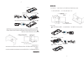
Packaging Contents
Please check all following items in a box and ensure that there are no missing or
damaged parts after opening.
No.
Name
Main unit
Quantity
1&
Washer-head wood screw 5.1 x 25
1
6
1
1
4
Oil tray
1
6
Operating Manual
5 . 1x25
1
1
2
3
4
3
2
1
Hx5$üNG¥[,¼ð»Î:
µ¶·¸¹Zhº»750mm。
1、³´ª
¼½´#¾¿ÀÁ Ã#¹Z,ÄÅhÆÇÈ。
×
2、ÉÊËÌÍÎÏÐÑ ÒÉ Ó, Ô)hÕÖ。
Øh×ÙÚ׳۽ÎÜo³2 ÝÞ Ó。
3、×ÉÊhßàá,5âãä1.5m,æçèéßIJÃ。
4、ê #«&4ëì,Jíî。
5、ï«ðIñ ò。
6、ó
Ú#ô18ãä48Þõ¥Î³Ûö÷øù',úûô
5.2kW$ü。
7、+ýÁöþðÿ。
8、XðýÁöï«
。
9、 、 #ή^ï«
z{。
2
3
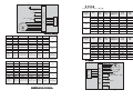
Technical Specifications
¦/²
220 - 240V ~
¥
S LM - 6 0 0 / 7 0 0 / 9 0 0 V(V e n t i l a t i n g T y p e)
Rated Voltage
(V)
Speed
Med
Hi
230
Med
Low
Hi
240
Frequency
(Hz)
Hi
220
Low
±
¤
®
220 - 240V ~ 40W
(N £)
( 8)
( 8)
(§ ¨)
(b ¨)
(« ¨)
¤
¥
¦
©
ª
¬
2 2 0 - 24 0 V ~
2.5μF/450V
M
Med
Low
50
50
50
50
50
50
50
50
50
Power Consumption
(W)
Power Consumption
with Lamp(W)
140
135
120
150
140
125
160
145
135
100
95
80
110
100
85
120
105
95
Air Flow
3
(m /h)
490
255
195
495
285
205
500
320
220
Sound
(dB)
59
45
37
59
48
38
60
49
40
S LM - 6 0 0 / 7 0 0 / 9 0 0 R(R e c y c l i n g T y p e)
240
Rated Voltage
(V)
Speed
220
Med
Low
Hi
230
Med
Low
Hi
240
Frequency
(Hz)
Hi
230
220
³´µ
(V)
¨·
¸¹
(Hz)
º»¼¹
(W)
º»¼¹½
®(W)
¾¿
3
(m /h)
ÀÁ
(dB)
Ǭ
b¨
§¨
Ǭ
b¨
§¨
Ǭ
b¨
§¨
50
50
50
50
50
50
50
50
50
95
85
75
105
90
80
115
95
85
135
125
115
145
130
120
155
135
125
190
130
90
190
140
100
195
150
110
59
49
39
59
51
41
60
52
43
Med
Low
S L M - 600 / 700 / 900R( )
50
50
50
50
50
50
50
50
50
Power Consumption
Power Consumption
(W)
with Lamp(W)
135
125
115
145
130
120
155
135
125
95
85
75
105
90
80
115
95
85
Air Flow
3
Sound
59
49
39
59
51
41
60
52
43
190
130
90
190
140
100
195
150
110
(dB)
(m /h)
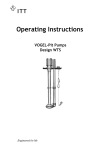
Wiring Diagram
(Public) blue
( Capacitor ) brown
( Capacitor ) yellow
( Low ) white
( Med ) grey
240
Switch
socket
230
M
220 - 240V ~
2.5μF/450V
( Hi ) black
Lamp
220 - 240V ~ 40W
Electrical
220
³´µ
(V)
¨·
¸¹
(Hz)
º»¼¹
(W)
º»¼¹½
®(W)
¾¿
3
(m /h)
ÀÁ
(dB)
Ǭ
b¨
§¨
Ǭ
b¨
§¨
Ǭ
b¨
§¨
50
50
50
50
50
50
50
50
50
100
95
80
110
100
85
120
105
95
140
135
120
150
140
125
160
145
135
490
255
195
495
285
205
500
320
220
59
45
37
59
48
38
60
49
40
Brown
220 - 240V ~
Blue
S L M - 600 / 700 / 900V( )
Yellow / Green
3
!,$"#$%
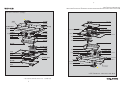
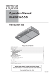
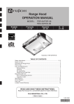
N ame of Parts
4
N 𤣤¥ª¢
SLM - 600 / 700 / 900V(Ventilating Type)
Lamp box
Exhaust port
Outlet cable block
Frame top plate
Frame external
chamber
Frame structure
Switch
Switch bracket
Capacitor
Seal strip
ãäâ
Connection base
Fixed part of lamp base
å¾â
á´â
Lamp base
Bulb
æçâ
æçâèé
®î
æçâï ÜÝ
ðâ
Internal chamber
5â
á´a
Fixed part
Motor fixed plate
Motor
Baffle plate
Internal plate
Air inlet plate
[ÜÝ
8
[
Rectifier panel hook
×êâ
×ëÝ
Ù
Lamp cover
Connection bracket
of rectifier panel
Panel
Þßà
5Û
® á´a
®
®ì
Ù
Ù
×ÚÛ
Rectifier panel
Ö Ø
Oil tray
®í
Ö¾×
S L M - 6 0 0 / 7 0 0 / 9 0 0 V()
Where any parts of the actual product differ from the drawing, the actual parts shall
prevail as the correct parts.
4
5
N 𤣤¥ª¢
!,$"#$%
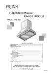
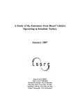
Name of Parts
SLM - 600 / 700 / 900R(Recycling Type)
Lamp box
Outlet cable block
æçâ
®î
æç â ï ÜÝ
ðâ
æç â èé
å¾â
5â
ãä â
Frame external
chamber
Frame top plate
Frame structure
Connection base
Fixed part of lamp base
Lamp base
Bulb
Seal strip
á ´â
Switch
Switch bracket
Capacitor
Internal chamber
Seal strip
ñò ó
Filter cartridge
Þ ßà
® á´ a
®
®ì
Þ ßà
Ù
Ù
5Û
[ÜÝ
8
[
× êâ
× ëÝ
Ù
× ÚÛ
Motor fixed plate
Motor
Baffle plate
Internal plate
Air inlet plate
Lamp cover
Connection bracket
of rectifier panel
Rectifier panel hook
Panel
Rectifier panel
®í
ÖØ
Oil tray
S L M - 6 0 0 / 700 / 900R( )
Where any parts of the actual product differ from the drawing, the actual parts shall
prevail as the correct parts.
5
6
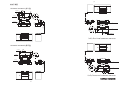
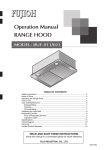
Installation Diagram
SLM-600/700/900V (Ventilating Type)
Power cord
220
120
145
210
50
Ø
500 . 600 . 800
490 . 590 . 790
18
120
50
R
3
≥750
460
71
278
Ø148
40
50
Mounting holes
≥750
Mounting holes
R
3
16
600 .700.900
500 . 600 . 800
16
210
Ø
50
460
120
600 .700.900
278
71
490 . 590 . 790
18
50
¡
220
SLM-600/700/900R ()
SLM-600/700/900R (Recycling Type)
Power cord
220
Ø
18
≥750
Mounting holes
R
3
16
120
50
278
40
490 . 590 . 790
71
500 . 600 . 800
Mounting holes
50
460
R
≥750
278
600 .700.900
71
50
460
Ø148
3
16
145
210
Ø
210
50
18
50
220
120
120
600.700.900
500 . 600 . 800
490 . 590 . 790
¡
SLM-600/700/900V ()
6
7
I nstallation
1. See below diagram, for proper placement of ductwork and electrical cutout in
cabinet.
In the case of Recycling Type, the processing of the vertical duct access hole
3 :1H<=,7üIJ。
is unnecessary.
Cutout for power cord
Cutout for ventilation
45
55
190
175 65
2 Dê*-,EüxFG。
200
20
Front face of cabinet
2. Remove an inner panel in the next step.
1 Loose the mounting screws attaching the rectifier panel, pull the rectifier
panel forward slightly to free the mounting screws from the mounting guide
1 :;ê*-#<=,>?@Aê*-,#<=#60BC。
holes.
2. 7ü9-。
200
20
2 Open the rectifier panel, remove the hook of the rear.
175 65
45
190
55
3 Remove a filter by loosing a screw.
ÄÚ1%2
1. 'ü¢X
,ï345ÊÓÐ6。
,ÏÉÊÓ
()*öýÁô+,-./0*。
screw
7
8
K&þðLM¼NO。
I nstallation
×Êm,ÏÉnJmo。
4 Remove an inner panel by loosing 4 or 6 screws.
ßIJá×Ê。
:
7. Ø150jÊk ô×Ôù。(lÿ)
6. bcªde¤fghi#
。
3. Referring to “Installation Diagram”, insert 4 wooden screws into a
bottom plate of the cabinet.
5. Sa2Hx<=。
Marking is recommended before screw.
About 5mm between the bottom plate and screwheads for hanging
the hood body.
5mm
4. Hook the temporary fixing holes of the body with screws, then slide
0*%K,`xSa4H<=。
the body backward until the screws are engaged in a narrow end of
K&
the holes.
F_¸6。
Ensure proper hood position, and tighten 4 screws.
4. <=GÐ
]^ýÁ6, ØxA5º<=¤
ô+,µ-ª<=WXYZ5mm,$[\F
5mm
Ø。
qrôSÐ<=?TUV。
5. Tighten 2 screws of the rear.
3. 'P“# ¢”X ,ô+,-µ¤Q34HR<=。
6. Assemble the hood in reverse procedure of section 2.
7. Connect Ø150 flexible duct to the exhaust port. (not supplied)
Note
Make the length of the duct as short as possible.
4 :;4HÎ6H<=,7ü9-。
The longer the exhaust duct, the lower the ventilation.
Ensure that there is no deformation such as flattening.
8
9
I nstallation
(Ventilating Type)
8. Make the exhaust port secure and air-tight using non-flammable tape
such as aluminium tape, etc. (not supplied)
Flexible duct
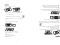
Operating Method
Taping with non-flammable
materials (Aluminium tape etc.)
1.Touch " " once to power up, then touch "
1
off the power.
33、ô“ ”÷øù,¼ÿ;ýô“
®。
22、
ô«¨
" again to turn
2.3 speeds from left to right are Low, Med and Hi which are
2
interlocked, that is, when Hi be pressed down, Med and Low speeds
cannot be pressed down. Touch Hi speed, the motor will run highly.
Touch Med speed, the motor will run mediumly and touch low speed,
the motor will run lowly.
3.Touch " " to turn on the light, then touch " " again to turn
3
off the light. The indicator light " " goes out.
11、ô“
«
”÷øù,¼ÿ[þ,“
”
)§b«3¨ ,3¨),«¨ô,¨Jÿô;
,ôb¨ b ,ô§¨ § 。
”÷øù,{û;ýô“
”÷øù,[þû。
³ n st ( qr st u )
Öpx。
jÊ
8. K&×ÔGÖpn,qrstu(lÿ)³nstvwÊ
Ô
(×2)
9
10
Points to Note on Maintenance
This product should be maintained regularly for optimal performance and to
prolong its usage lifespan.
Warning
(1) To ensure safety, unplug the unit from the power source before maintenance.
(2) Never allow the motor and electrical parts to get wet!
(3) Do not leave the stove on when not in use or flaming. Do not allow the stove
flames to directly burn the cooker hood.
(4) Clean off oil grime that has collected in the oil tray in a timely manner. When
12、ó
Ú#ô18ãä48Þõ¥Î³Ûö÷øù',úûô
5.2kW$ù。
removing the oil tray, use both hands to grasp both ends of the oil tray and
10、 ü£¥@C,$§NLM、¼¶½¹。
gently pull down towards your chest.
11、l®¾|~ ®!
ð »²。
(5) When the cooker hood is being use to clear fumes from a stove flaming gas
9、 ^µ~¶·¸Ô¹;°n°±²Gj³j´,|~
ðx¨©。
(6) When the light bulb is damaged, please replace it with a light bulb of the same
type, with a maximum rating of 1.5W.
,_
(7) If the power cord is damaged, it must be replaced by a trained service technician
of fire.
,ô
from the manufacturer, its maintenance department or a similar representative,
>?@
9
to avoid any hazards.
4、
(8) If the cooker hood is not cleaned as stipulated by the manual, there is the risk
、ܨ®¤Î¬¤®
ô÷´½ÎÜo³2,Xï«ÏÉ;<。
。
or other fuels, the room must be kept well ventilated.
8、 ¼¥¾¿¯ÀÁ'b°
。
7、 ¼¥¡,$¦§¨©,﫪«
6、 P¿,!2,ÃÚ1.5W。
5、
I。
3、 |~½´Û ³;|~÷5
2、 Õ| G¤¥zë!
(9) Be careful not to cut your hand on the sharp metal opening while cleaning the
1、 &z?{,K&。
unit; use a neutral detergent and soft cloth to clean. Never use organic solvents
:
on this product.
(10) Place all removed parts carefully on a surface to prevent the product from
· nJ,¡¢£,h¤&z。
becoming deformed or scratched.
$ó
(11) The product must never be disassembled by an untrained service technician!
10
11
(12) The range hood is intended to be installed over a hob with up to four hob
elements or burners, no more than total 5.2kW.
Maintenance
1. Hood surface cleaning
After each use wipe the range hood’s external surface with a soft cloth.
2. Oil tray cleaning
It is recommended drain oil from oil tray regularly.
3. Rectifier panel and Filter cleaning
It is recommended that it be cleaned once a month.
Remove by the procedure described on page 7.
ô P¿ W?, Ü ïK& ªÝ ¶ ) Î Þßà ) ö 。
K& f! × N P¿ z { 。
Always use both hands to carefully grasp all parts being removed to prevent them
from falling and becoming damaged.
Please watch out for oil that has collected in the rectifier panel.
4. Replacing a light bulb
4 . P¿
$ µ ~ )Ê ö & © Ë ÌÛÍ , Î Ïм üÑ Ò Ó ÔÎÕ J
z { 。
Ö ÁN
220/230/240V( × N)
µ 5 é
14mm
· Ã5 é
≤42mm
P ¿ Û
≤132mm
Ó Ô →≤40W
ÕJ → ≤8W
3 .° ê * J
q rÀ Æ °5u 。
' P Ƕ7X Ü 7 ü。
ô È £¤¥ , _£ ¤¥ , µ~{ É 。
ê* -9 {É 。
1 . °
¼¶
À u Ásx , j ³ÂÃ
Í ¼¶ 。
2 .°
q r' P
ù àÄ
Á Å
。
In case of blowout,
please replace a light bulb with a commercially purchased mini light bulb or compact
fluorescent light bulb (CFL) described below.
Rated voltage
220/230/240 (Supply voltage)
Diameter of the base
14mm
132mm or less
Length of the light bulb
42mm or less
Diameter of the largest
Power consumption
In the case of the mini light bulb→40W or less
In the case of the compact fluorescent light bulb→8W or less
Note
Before replacing a light bulb, ensure to disconnect the power plug from the wall
receptacle, or switch off the breaker.
&z ª ¨ ©
When replacing, be sure to use a light bulb with same voltage to supplied voltage.
11
12
Self-check
In the event of any uncertainties or questions regarding repairs, please
consult the shop where you purchased this product. Please stop using
the cooker hood if it is not functioning normally. The cooker hood must
not be dismantled or repaired by an untrained service technician!
(*)P¿:®öx÷Üz{¨®。
û 6、°
4、
5、°
Îãö。
3、Æ$êê
Solution
1、êê#éÛ。
2、 ô%=
Possible cause
1、#äé
2、%=Ä*
ëÃ
3、×ÉÊÔèìÎ
~íÉæîÌï_
4、 æð¿ñä
5、X ^,æ
çÎ Ìò_
6、I J- ëó
Defect
1、å #Ù0
2、æç#Ù0
3、¨®
1. Check whether the socket has
power or insert loose plug securely
into socket.
2. Repair or replace.
3. Repair or replace.
1、å #Ù0
2、æç#Ù0
3、æçèLM
1. Replace motor.
2. Replace capacitor.
1. Replace light bulb.
1. Install the main unit correctly.
2. Install the fan correctly.
3. Repair or replace.
1. Adjust the installation height.
2. Improve the environment where
the unit will be used.
3. Make adjustments.
4. Replace the motor or capacitor.
5. Clean the unit.
6. Clean the filter.
Ø ä ;
1. Socket has no power or plug
not inserted securely.
2. Damaged switch.
3. Short circuit.
1、P¿
Motor does not
run
Light does not
come on
1、P¿
1. Motor burnt out.
2. Capacitor damaged.
â æ
P¿á
Lamp comes on
Motor does not
come on
1、
2、ãö
1. Damaged light bulb.
1、 Û
2、ãö
Motor run
Light does not
come on
P ¿ á
âæ
Unit vibrates
3、¨®
1. Main unit installed incorrectly.
2. Fan installed incorrectly.
3. Fan is damaged and
malformed.
3、)Ê
)^'b
Poor suction
power
1、[ð,
a:;
2、¨®
IJúû
1. Installation point is too high.
2. Ambient air convection is too
strong.
3. Exhaust duct outlet is obstructed
or air flow blade is jammed.
4. Fan operation speed is evidently
low.
5. Unit has not been cleaned for
a long time, the fan or motor is
sticking.
6. Excessive oil build up on filter.
1、`Î a
2、ß
â æ
P ¿ á
W ø ù
dJdP "#,!$%&&'åz ( 。
f)
d*+),,!-. 。/01234.5P!
(*)Replacement of light bulb: servicing should be carried out by a trained
after-sales service technician.
12
13
Service and Parts
When requesting repair:
If any abnormality occurs while the cooker hood is in operation , switch
off the cooker hood to run, check the following points, disconnect the power
plug from the receptacle and consult the shop from which you have purchased
your cooker hood.
(1) Whether the fuse in the circuit breaker has been burnt out?
(2) Whether the power plug is not in proper contact with the receptacle?
When consulting the shop, inform the shop the type/model of cooker hood
requiring repair and the date when it was purchased.
5
years
:
b s ta mÿW uv] e ÿ?v w ,xJ y z{| 。
&w x u dyz wv, x Jyz { |。
ø{ | }h~ e& ) 。
P 7 a M d :
e ÿ 7a 。
f M , g d Zh¼ÿ P 7 aw i7 ajk l _`4]。
Pc ¼ ÿmhn h d, o p)_ ` Pq r 。
The minium retention period of performance parts for repairing
the cooker hood is 5 years after termination of manufacturing
of the cooker hood.
The performance parts refer to those parts for required to maintain the
functions of a cooker hood. However the same kinds of repair parts or
interchangeable parts will be supplied for 4 years thereafter.
If the functions can be maintained when repaired, we are willing to repair
when ordered by you.
The parts used on the cooker hood are subject to partial change without
prior notice owing to improvement of performance.
5]
p^P7 a_` \ a ) :
K C D E 'j( ,! |W8 9P X :
- . bc5]。
Y/ Zh o % [\。
( 2 ) û?B M NTU V ?K? @?
(1)H I J b* K LMN O PQR?
8 9 P :
:
z Ö)B C *+, ![ ;[ , <jh =>,? @ A ; û?B , C %:
DE 'F Gj (。
P
P:
:7a
13
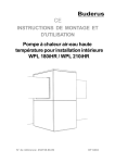
FUJIOH INTERNATIONAL TRADING PTE . LTD .
130 Joo Seng Road #05 - 05 Singapore 368357
Tel: (65) 6286 3286
Fax: (65) 6285 3285
E-mail: [email protected]
üýþ òÿú¤
üýþòÿú¤
www.fujioh.com
ð
ð
G lobal website
www.fujioh.com
Southeast Asia Regional Headquarters
FUJIOH INTERNATIONAL TRADING PTE . LTD .
130 Joo Seng Road #05 - 05 Singapore 368357
Tel: (65) 6286 3286
Fax: (65) 6285 3285
E-mail: [email protected]