1
UM1530
User manual
Smart meter demonstration board with DLMS/COSEM using
ST7570 S-FSK modem with STM32™ and SPEAr™
Introduction
The purpose of this user manual is to help the user to set up, run and evaluate a complete
solution that demonstrates a smart metering system based on one or several electricitymeters, one data concentrator, and using the DLMS/COSEM application libraries (server
and client) from ANDREA Informatique and hardware and firmware from
STMicroelectronics™. The communication medium is based on power line communication
(PLC) with a modulation technique used in IDIS (specifications) meters or in Linky G1
meters based on the IEC 61334-5-1 standard.
ANDREA Informatique and ST Microelectronics have agreed to promote an easy way to
obtain DLMS/COSEM ready-to-use smart metering solutions.
With this demonstration setup it is possible to evaluate how easy it is to build a complete and
robust system.
For instance, on this demonstration board the power, time and status of the breaker and
other information stored in the power meter can be shown on an LCD display of the meter or
sent to the data concentrator through a power line communication system.
The E-meter demonstration board is based on the STM32F103VE microcontroller, ST7570
PLM modem, ALTAIR04-900 power supply IC, and, optionally, STPMC1/S2 poly-phase
energy metering ICs. It implements a PLM smart meter node which allows the final utility to
monitor energy consumption and other electrical parameters on one or more phases.
The concentrator is based on the SPEAr microprocessor and the ST7570 power line
modem (PLM).
July 2012
Doc ID 022957 Rev 1
1/26
www.st.com
Contents
UM1530
Contents
1
Description . . . . . . . . . . . . . . . . . . . . . . . . . . . . . . . . . . . . . . . . . . . . . . . . . 4
1.1
Introduction . . . . . . . . . . . . . . . . . . . . . . . . . . . . . . . . . . . . . . . . . . . . . . . . 4
1.2
IEC 61334 (S-FSK) . . . . . . . . . . . . . . . . . . . . . . . . . . . . . . . . . . . . . . . . . . 6
S-FSK modulation and ST7570 PLM . . . . . . . . . . . . . . . . . . . . . . . . . . . . . . . . . . . . 6
1.3
IEC 62056 (DLMS/COSEM) . . . . . . . . . . . . . . . . . . . . . . . . . . . . . . . . . . . . 7
DLMS/COSEM library . . . . . . . . . . . . . . . . . . . . . . . . . . . . . . . . . . . . . . . . . . . . . . . 8
1.4
1.5
STEVAL-IPP002V1 smart meter demonstration board . . . . . . . . . . . . . . . 8
1.4.1
Hardware . . . . . . . . . . . . . . . . . . . . . . . . . . . . . . . . . . . . . . . . . . . . . . . . . 8
1.4.2
Firmware . . . . . . . . . . . . . . . . . . . . . . . . . . . . . . . . . . . . . . . . . . . . . . . . 11
EVALSPEAr320HMI data concentrator . . . . . . . . . . . . . . . . . . . . . . . . . . 13
1.5.1
Hardware . . . . . . . . . . . . . . . . . . . . . . . . . . . . . . . . . . . . . . . . . . . . . . . . 15
1.5.2
Firmware . . . . . . . . . . . . . . . . . . . . . . . . . . . . . . . . . . . . . . . . . . . . . . . . 16
1.5.3
Web interface . . . . . . . . . . . . . . . . . . . . . . . . . . . . . . . . . . . . . . . . . . . . . 19
1.5.4
Real hardware demonstration setup . . . . . . . . . . . . . . . . . . . . . . . . . . . 22
2
References . . . . . . . . . . . . . . . . . . . . . . . . . . . . . . . . . . . . . . . . . . . . . . . . 24
3
Acronyms . . . . . . . . . . . . . . . . . . . . . . . . . . . . . . . . . . . . . . . . . . . . . . . . . 25
4
Revision history . . . . . . . . . . . . . . . . . . . . . . . . . . . . . . . . . . . . . . . . . . . 25
2/26
Doc ID 022957 Rev 1
UM1530
List of figures
List of figures
Figure 1.
Figure 2.
Figure 3.
Figure 4.
Figure 5.
Figure 6.
Figure 7.
Figure 8.
Figure 9.
Figure 10.
Figure 11.
Figure 12.
Figure 13.
Application block diagram . . . . . . . . . . . . . . . . . . . . . . . . . . . . . . . . . . . . . . . . . . . . . . . . . . . 4
Block diagram of the complete application . . . . . . . . . . . . . . . . . . . . . . . . . . . . . . . . . . . . . . 5
Block diagram of the complete software stack used in the application. . . . . . . . . . . . . . . . . 6
STEVAL-IPP002V1 smart meter demonstration board . . . . . . . . . . . . . . . . . . . . . . . . . . . . 9
STEVAL-IPP002V1 smart meter demonstration board block diagram . . . . . . . . . . . . . . . . 10
E-meter application running on STEVAL-IPP002V1. . . . . . . . . . . . . . . . . . . . . . . . . . . . . . 13
SPEAr320 microprocessor unit block diagram . . . . . . . . . . . . . . . . . . . . . . . . . . . . . . . . . . 14
EVALSPEAr320HMI - block diagram . . . . . . . . . . . . . . . . . . . . . . . . . . . . . . . . . . . . . . . . . 15
EVALSPEAr320HMI - board running, screen capture . . . . . . . . . . . . . . . . . . . . . . . . . . . . 19
User interface - evidence of the connected E-meters. . . . . . . . . . . . . . . . . . . . . . . . . . . . . 20
User interface - detailed information about the chosen E-meter. . . . . . . . . . . . . . . . . . . . . 21
Real E-meter demonstrator . . . . . . . . . . . . . . . . . . . . . . . . . . . . . . . . . . . . . . . . . . . . . . . . 22
Real concentrator demonstrator (S-FSK modem on the top left) . . . . . . . . . . . . . . . . . . . . 23
Doc ID 022957 Rev 1
3/26
Description
1
UM1530
Description
Warning:
1.1
The boards must be used only by expert technicians. Due to
the high voltage (220 VAC) special care should be taken with
regard to human safety. There is no protection against
accidental human contact with high voltages. After
disconnection of the board from the mains, none of the live
parts should be touched immediately because of the
energized capacitors. It is mandatory to use a mains
insulation transformer to perform any debugging/tests on the
board in which debugging and test instruments like
USB/JTAG dongles, spectrum analyzers, or oscilloscopes are
used. Do not connect any oscilloscope probes to high
voltage sections in order to avoid damaging instruments and
demonstration tools. STMicroelectronics assumes no
responsibility for any consequences which may result from
the improper use of this tool.
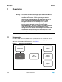
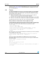
Introduction
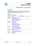
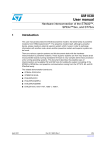
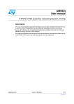
In order to build a power line demonstration system, at least one concentrator and one
meter are required. Optionally, the user can connect more meters (up to 8) and a network
SPY (refer to the AN3213 application note), see Figure 1.
Figure 1.
Application block diagram
#ONCENTRATOR
0#
-ETER
309
OPTIONAL
-ETER
OPTIONAL
-ETERX
OPTIONAL
!-
4/26
Doc ID 022957 Rev 1
UM1530
Description
IEC 61334 (S-FSK), and IEC 62056 (DLMS/COSEM) are performed on:
●
STEVAL-IPP002V1 (E-meter) and
●
EVALSPEAr320HMI (concentrator).
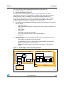
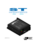
The demonstration board, depicted in Figure 2, aims to demonstrate, to meter
manufacturers, how easy it is to implement a complete smart meter solution using the
STMicroelectronics HW and ANDREA Informatique SW (DLMS/COSEM stack).
The stack and user interface running on the concentrator, depicted in Figure 3, allows
access to the remote E-meters. It is possible to work with the different data objects
(DLMS/COSEM) in the E-meter through power line communication:
●
●
The objects can provide different information and perform some actions, for instance,
they are able to:
–
read energy values
–
read load profile, reading each 15 minutes over 2 days (stored in the memory of
the E-meter)
–
read the clock
–
set the clock
–
disconnect and reconnect the breaker
–
send a message to the customer (to the E-meter display)
–
change tariff
The information and actions that objects provide can be interfaced through a web
server/web pages:
–
up to 8 meters can be accessed in one moment
–
real-time indication about a number of the connected meters and their status
–
graphical representation of the load profile
–
bi-directional communication with the meter using buttons or text command
window.
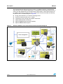
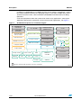
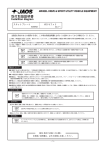
Figure 2.
Block diagram of the complete application
#,)%.4CONCENTRATORIN$,-3
%6!,30%!R(-)
3%26%2METERIN$,-3DEF
%6!,+)434
34%6!,)006
53"
34-
&
30%!R
%THERNET
34
6
,#$
34%6!,)0%6
34
340-#
3ERVERNO
(5"
3ERVERNO
0#
3ERVERNO
7EB'5)UTILITYVIEW
!-
Doc ID 022957 Rev 1
5/26
Description
UM1530
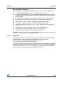
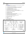
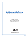
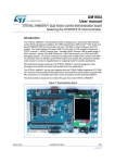
Figure 3.
Block diagram of the complete software stack used in the application
#,)%.4CONCENTRATORIN$,-3
3%26%2METERIN$,-3DEF
#/3%-OBJECTS
$,-3LIBRARY
)%#,,#LAYER
#/3%-OBJECTS
$,-3,)"LIBRARY
)%#,,#LAYER
7EBSERVER
)0STACK
)%#
)%#
%THERNET
3&3+0(9AND-!#
3&3+0(9AND-!#
!PPLICATION
!LLOBJECTS
FROM
34%6!,
)006
24/3
,INUX
!-
1.2
IEC 61334 (S-FSK)
IEC 61334-5-1 describes the requirements of the S-SFK (frequency shift keying modulation)
in conjunction with the services provided by the physical layer entity and the MAC sub-layer.
The transmission medium is assumed to be the distribution network. The MAC sub-layer
described in this standard interfaces with the logical link control layer described in
IEC 61334-4-32.
The 3-part modulation, physical layer and MAC sub-layer are embedded in the ST7570 so
that the best cost/performance ratio may be achieved.
The profile described in this standard is one of several profiles (described in series
IEC 61334-5) which are all designed for data transmission via the distribution network.
Considering the ongoing technical development in this field, the profiles are published first
as technical specifications with the intention to transform, into standards, those profiles
which are successful in practice (IEC 61334-5-1).
IEC 61334-5-1 is used in the IDIS specifications or Linky G1.
IEC 61334-5-1 can bridge to the DLMS/COSEM communication standard through the
convergence layer IEC 61334-4-32.
S-FSK modulation and ST7570 PLM
S-FSK modulation uses two tones for communication, one frequency for the “0” and one
frequency for the “1”. The two tones must be more that 10 kHz apart; when one tone is
masked by a strong noise, the other one can be read in AM mode. This makes the system
robust to narrow band noise. The ST7570 is a powerful power line networking system-onchip. It combines a high-performance PHY processor core and a protocol controller core
with a fully integrated analog front-end (AFE) and line driver. The ST7570 features allow the
most cost-effective, single-chip power line communication solution based on the
IEC 61334-5-1 S-FSK standard. It offers 1 Hz step programmable carriers up to 148.5 kHz.
6/26
Doc ID 022957 Rev 1
UM1530
Description
The ST7570 embeds a full physical (PHY) and a medium access control (MAC) protocol
layer and services compliant with the open standard IEC 61334-5-1, mainly developed for
smart metering applications, but suitable also for other command and control applications
and remote load management.
A local port (UART) is available for communication with an external host, exporting all the
functions and services required to configure and control the device and its protocol stack.
The protocol layers and functions embedded in the ST7570 are:
Physical layer: implemented in the PHY processor and exporting all the primitive functions
listed in the international standard document IEC 61334-5-1, plus additional services for
configuration, alarm management, signal and noise amplitude estimation, phase detection
and statistical information.
MAC layer: implemented on the protocol controller and exporting all the primitive functions
listed in the international standard document IEC 61334-5-1, plus additional services for
configuration.
Management information base (MIB): an information database with all the data required
for proper configuration of the system (at both PHY and MAC layer).
Host interface: all the services of the PHY, MAC and MIB are exported to an external host
through the local UART port.
1.3
IEC 62056 (DLMS/COSEM)
IEC 62056 is a set of standards for electricity metering. The IEC 62056 standards are the
international standard versions of the DLMS/COSEM specification. DLMS or “device
language message specification” is the suite of standards developed and maintained by the
DLMS User Association. The DLMS User Association (UA) has established a D Type liaison
with IEC TC13 WG14, responsible for international standards for meter data exchange and
establishing the IEC 62056 series.
The DLMS UA provides maintenance, registration and conformance testing services for
IEC 62056 DLMS/COSEM. COSEM or “companion specification for energy metering”,
includes a set of specifications that defines the “transport and application layers” of the
DLMS protocol. The DLMS User Association defines the protocols in a set of four
specification documents, namely, Green Book, Yellow Book, Blue Book and White Book.
The Blue Book describes the COSEM meter object model and the object identification
system, the Green Book describes the architecture and protocols, the Yellow Book treats all
the questions concerning conformance testing, the White Book contains the glossary of
terms.
The standards included in this demonstration setup, on top of the IEC 61334, are:
–
IEC 62056-4-32: Distribution automation using distribution line carrier systems Part 4: Data communication protocols - Section 32: Data link layer - Logical link
control (LLC)
–
IEC 62056-53: COSEM application layer (this specification has now been
withdrawn by IEC)
–
IEC 62056-61: Object identification system (OBIS)
–
IEC 62056-62: Interface classes.
Doc ID 022957 Rev 1
7/26
Description
UM1530
Other standards, such as the ones below, are not covered by the demonstration setup and
should be requested from ANDREA Informatique in order to comply with other
requirements:
●
IEC 62056-21: Direct local data exchange (3rd edition of IEC 61107) describes how to
use COSEM over a local port (optical or current loop)
●
IEC 62056-42: Physical layer services and procedures for connection-oriented
asynchronous data exchange
●
IEC 62056-46: Data link layer using HDLC protocol
●
IEC 62056-47: COSEM transport layers for IPv4 networks.
DLMS/COSEM library
ANDREA Informatique has implemented both DLMS/COSEM libraries (client and server).
The DLMS/COSEM libraries comply with the IEC 62056 series of standards. They have
been written in C++ and the server library has been optimized for running in the STM32
microcontroller.
The main features of the libraries (client and server) are:
●
Easy-to-use interface to integrate DLMS/COSEM objects
●
Easy-to-use interface to integrate any modem: S-FSK, PRIME(a), GPRS(a), etc.
●
Management of Short and Logical Names
●
Short names: Read, Write and Information Report
●
Logical names: Get, Set, Action and Event Notification
●
COSEM security (AES128-GCM)(a)
●
Authentication (LLS, HLS-MDS, HLSSHA1, HLS-GMAC)(a).
For more information, please download relevant images and documentation at:
www.cosemlibs.andrea.fr.
1.4
STEVAL-IPP002V1 smart meter demonstration board
The E-meter demonstration board (STEVAL-IPP002V1) is based on the STM32F103VE
microcontroller, ST7570 PLM modem, and can be connected to the STPMC1/S2 poly-phase
energy metering IC demonstration board. It implements a PLM smart meter node which
allows the final utility to monitor energy consumption and other electrical parameters of the
meter.
The voltage, current, power, power factor, THD, active and reactive energy, and other stored
information can be shown on an LCD display locally, or sent to a PLM data concentrator
through a power line communication network based on the IEC 61334-5-1 standard protocol
and DLMS/COSEM application data objects.
1.4.1
Hardware
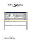
The application described in this document refers to the STEVAL-IPP002V1 demonstration
board depicted in Figure 4 (see www.st.com).
a. Not demonstrated in this specific demonstration setup.
8/26
Doc ID 022957 Rev 1
UM1530
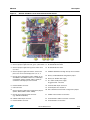
Figure 4.
Description
STEVAL-IPP002V1 smart meter demonstration board
1. TFT LCD color display 320 x 240
11. Boot configuration jumpers (SW7, SW9)
2. General purpose application red, green, yellow LEDs 12. Enable/disable DL2 LED
3. General purpose application joystick, switch meter
user data
13. Enable/disable DL1 LED
4. General purpose application button, switches the
phase view on the LCD display from 3, R, S, T
14. STM32F103VET6 32-bit high density microcontroller
5. Energy meter configuration jumper (SW10) to use
SPI-MISO or SPI-MOSI for data line, LCD display
configuration jumpers (SW16, SW17, SW18) to
control the LCD display via SPI of GPIO
15. Battery enabled/disabled configuration jumper
16. Battery for STM32 VBAT supply
17. 85 - 256 V board power supply.
Suggested 110 - 220 V AC
6. RS232 USART connector
18. ST7570 JTAG 10-pin connector
7. USB connector
19. ST7570 power line modem IC
8. General purpose application configuration jumpers
(SW19, SW20, SW21, SW22, SW23)
20. RTC calibration/normal mode configuration jumpers
9. Energy meter external board connector
(e.g. STEVAL-IPE010V2)
21. STM32 microcontroller reset button
10. STM32 JTAG 20-pin connector
22. ST7570 PLM IC UART connection connector
6. RS232 USART connector
23. ST7570 PLM IC reset button
Doc ID 022957 Rev 1
9/26
Description
UM1530
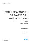
The E-meter demonstration board can be used as a guideline to design a typical energy
meter board for smart metering applications. It is designed to include advanced features as
well as to fit the requirements for next generation energy meters. These extra features can
be added to the board by modules for easy customizing. The board includes the following
functions shown in the block diagram in Figure 5:
Figure 5.
10/26
●
Energy measurement by an external metrology board
●
Power line communication up to 2.4 Kbps
●
LCD display to show energy consumption information
●
USB and RS232/IrDA connectivity
●
Optional ZigBee® communication capability
●
Optional MEMS module support.
STEVAL-IPP002V1 smart meter demonstration board block diagram
Doc ID 022957 Rev 1
UM1530
Description
Main hardware components
The E-meter demonstration board (STEVAL-IPP002V1) main hardware components are:
●
An STM32F103VE microcontroller running the application firmware
●
An external optional STPMC1 multiphase energy metering IC; the external STEVALIPE010V1 demonstration board based on STPMC1 and STPMS2 has been used in this
firmware release
●
An MB542B-01 320x240 color TFT LCD display module; used to show data locally
●
An ST7570 power line modem; used to provide PLC connectivity to the system
●
3 status LEDs; 1 green, 1 yellow, 1 red LED for application status scope
●
1 I2C expansion connector for dual interface EEPROM connection (J8)
●
5 configuration jumpers (SW19, 20, 21, 22, and 23); used for software configuration
scope
●
1 user button (S1) and 1 joystick (U8); used for user application scope
●
1 microcontroller reset button (SW4); used to force an MCU reset
●
1 modem reset button (SW1); used to force an ST7580 reset.
Detailed information about the smart meter demonstration board hardware and its setup can
be found in Section 2: References (STEVAL-IPP002V1).
1.4.2
Firmware
The demonstration board can be programmed by the included JTAG connector using any
JTAG programming tool for STM32. The ST-LINK tool is the one delivered by
STMicroelectronics, for more information on how to get it, refer to
www.st.com/internet/evalboard/product/251168.jsp.
It is necessary to program the STEVAL-IPP002V1 board before connection to the STEVALIPE010V1, in order to keep the insulation from the mains; in fact the STEVAL-IPP002V1 is
insulated by default, but as soon as it is connected to the metrology board the insulation is
lost due to the not insulated topology of the STEVAL-IPE010V1.
Doc ID 022957 Rev 1
11/26
Description
UM1530
There are two ways to program FW into the STEVAL-IPP002V1:
Using IAR™ programming environment
The advantage of using this approach is that the user can add its tasks, modify the firmware
code and debug the code. The user unpacks the project archive to the new folder, finds the
main project file with *.eww extension and opens this project file in IAR programming
environment. Clicking the “download and debug” button downloads the firmware into the
STM32 Flash through J-Link, JTAG tool, ST-LINK or any of those supported in the project
option - debugger.
IAR programming environment can optionally generate a binary output suitable for later
flash programming of the microcontroller. This option can be found in the converter section
of the IAR project option. The binary outputs that IAR may generate are:
●
BIN file with *.bin extension
●
Intel® HEX file with *.hex extension
●
Motorola S-record file *.srec extension.
Using STM32 ST-LINK utility
The advantage of using ST-LINK utility is the simplicity of the flashing of the firmware and
the cost. The user does not need to compile a whole project or have source files. The setup
of the complex programming environment is not necessary. ST-LINK utility is very simple to
use.
The user clicks on the button “open file” and chooses the binary file to flash with one of the
following extensions that the ST-LINK utility supports:
●
BIN file with *.bin extension
●
Intel HEX file with *.hex extension
●
Motorola S-record file *.srec extension.
The “Program” button, that is immediately offered by the utility or can be found later in the
main menu, programs the microcontroller flash with the chosen binary file via the connected
ST-LINK adaptor.
Once the 3-phase system is put in place according to the previous description and the
system is powered on, the Smart E-meter application shows the following view on the LCD
display (see Figure 6).
12/26
Doc ID 022957 Rev 1
UM1530
Description
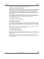
Figure 6.
E-meter application running on STEVAL-IPP002V1
1. Phase identification (3, R, S, T).
5. Power factor or “No Load” if no load
condition is detected.
2. Energy counter in kilowatt hour. Red digit
represents tenths kWh.
6. Meter user data. Use joystick to move
shown data.
3. Phase current in Amperes.
7. Phase THD parameter in percentage.
4. Phase reactive energy in kVAr.
9. Phase voltage in Volts.
If the application is running without problem, the LED (LED1) is seen blinking. During
counter moving the red LED (LED0) blinks every time the red number (tenth Watt-hours)
moves to the next step. To move from a phase view to the next phase view, it's necessary to
press user button S1. Joystick U8 allows user data to be moved.
In order to keep the connection to the power measurement board (STPMxx) optional, the
power information is simulated.
1.5
EVALSPEAr320HMI data concentrator
The data concentrator consists of the EVALSPEAr320HMI expansion board connected to
the EVALST7570-1 power line mode evaluation kit, as depicted in Figure 2 on page 5.
The EVALSPEAr320HMI expansion board hosts the SPEAr320 MPU:
●
The SPEAr320 is a member of the SPEAr family of embedded MPUs, optimized for
industrial automation and consumer applications. It is based on the powerful
ARM926EJ-S processor (up to 333 MHz), widely used in applications where high
computation performance is required.
Doc ID 022957 Rev 1
13/26
Description
UM1530
In addition, the SPEAr320 has an MMU that allows virtual memory management - making
the system compliant with the Linux operating system. It also offers 16 KB of data cache,
16 KB of instruction cache, JTAG and ETM™ (Embedded Trace Macrocell™) for debug
operations.
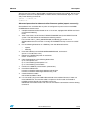
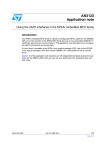
A full set of peripherals allows the system to be used in many applications, some typical
applications being factory automation, printer and consumer applications, see Figure 7.
Figure 7.
SPEAr320 microprocessor unit block diagram
%-)./2&LASH
&0'!INTERFACE
5PTO'0)/S
&3-#.!.$
&LASHINTERFACE
-OBILE$$2$$2
MEMORYCONTROLLER
X%THERNET
3-))-))INTERFACE
X#!.
X5!24
,#$CONTROLLER
,#$CONTROLLER
X
-ULTICHANNEL$-!CONTROLLER
)R$!¤
3ERIAL&LASHINTERFACE
53"DEVICE0(9
#CRYPTOACCELERATOR
XGENERALPURPOSETIMER
*0%'CODECACCELERATOR
X07-TIMER
3$)/--#CARDINTERFACE
+"YTES"OOT2/-
53"
HOST
0(9
(UB
0(9
!$#
+"YTES32!-
)NTERRUPTCONTROLLER
7ATCHDOG
X330
3YSTEMCONTROLLER
24#
0,,S
--5
XMASTERSLAVE
!2-%*3
AT-(Z
3TDPARALLELPORT
)#ACHE
$#ACHE
*4!'TRACE
&UNCTIONSWITHSHARED)/SDEPENDINGONTHEDEVICECONFIGURATION
!-
14/26
Doc ID 022957 Rev 1
UM1530
1.5.1
Description
Hardware
The EVALSPEAr320HMI expansion board contains the following peripherals available to
use (see Figure 8):
Figure 8.
●
1 x Ethernet RJ45 connector (ST802RT1A)
●
1 x LCD display interface for 5.7" 640 x 480 EDT screen (ET057010DHU)
●
1 x unified LCD display interface (EDT displays with unified interface)
●
1 x resistive touchscreen interface (STMPE811)
●
2 x CAN DB9 plug connectors
●
3 x RS232 DB9 plug connectors (ST3232EBTR)
●
Onboard temperature sensor and potentiometer (STMPE811)
●
64-Kbit dual interface EEPROM: ISO 15693 and ISO 18000-3 mode 1 compliant
●
Contactless interface + I2C (M24LR64)
●
4-Gb NAND Flash memory
●
PWM mono audio output
●
Analog extension connector featuring 8 ADC lines
●
General purpose extension connector with GPIOs and I2C functionality
●
Unified power line modem (PLM) connector
●
Raisonance Primer2 extension board interface connector
●
DC-DC converter L7986A (+24 V/+5 V)
●
Micro SD Card™ socket
●
4 LEDs
●
2 general purpose buttons
●
System reset button.
EVALSPEAr320HMI - block diagram
Doc ID 022957 Rev 1
15/26
Description
UM1530
Detailed information about the EVALSPEAr320HMI expansion board and the SPEAr MPU
can be found in Section 2: References (EVALSPEAr320HMI). The UM1045 user manual,
rev. 3, should be read first.
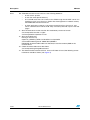
1.5.2
Firmware
The EVALSPEAr320HMI board can boot a Linux kernel pre-installed in the parallel NAND
Flash memory. At power-on, the serial port outputs a brief header message with some UBoot information (U-Boot version, SDK version, and some internal hardware information).
At this point the user can choose to:
●
Stop the system directly in U-Boot: Before the boot delay time expires (default is
3 seconds), press the spacebar on the host computer's keyboard.
●
Boot Linux: The system boot is finished when the login prompt appears in the console.
●
Boot Linux: The system boot is finished when the login prompt appears in the console.
The default login user name for super user is ‘root’; no password is required.
Basic procedure for demonstration firmware update (all users)
In order to update the uImage of the Linux firmware and boot parameters, the user can do
so under SPEAr board loader uboot (prerequisites are: any TFTP server running on any PC
and under any operational system). Uboot commands should follow this order:
> tftp 0 uImage
> nand erase 180000 220000
> nand write.jffs2 0 180000 220000
> setenv bootcmd nand read.jffs2 0x0 0x180000 0x220000\; bootm 0x0
> setenv bootargs console=tty0 mem=128M root=/dev/mtdblock7
rootfstype=yaffs2 ro init=/sbin/init
> saveenv
File system update can be performed via booting from another FS (an nfs boot is presented
here, but USB can be used as well):
> setenv bootargs console=ttyS0 mem=128M root=/dev/nfs init=/sbin/init
nfsroot={serverip}:/tftpboot/fs ip=::::SPEAr320::on
> boot
After the new image is downloaded into the SPEAr board, the user must put these
commands in order to install the new file system from the new image in the SPEAr board
Linux command line:
# mount -t yaffs2 /dev/mtdblock7 /mnt/nand
# cd /mnt/nand
# rm * -R
# tar xvf /home//meetering_fs.tar.bz2
# vi /etc/init.d/rcS
: at the eof switch virtual FTDI ports of metering daemons /dev/ttyUSB1 <->
/dev/ttyUSB0
16/26
Doc ID 022957 Rev 1
UM1530
Description
After the new file-system is downloaded, installed in the board and is funtional, the last fix to
the Apache server must be performed. In order to do this, boot the board, login as a ‘root’
and put the following commands:
# mount -o remount,rw /
# chmod +x /
Advanced procedure for demonstration firmware update (expert users only)
Choose Boot Linux and follow the 14 points to configure the system and run the DLMS/
COSEM demonstration board:
1.
Compile the demonstration board set on a Linux host, equipped with SPEAr tool chain:
cd /xxxxxxxx/metering
make
2.
Take a brand new, out-of-the-box, EVALSPEAr320HMI board, with NAND Flash file
system. The flashed kernel should be the following version:
Linux version 2.6.27_stm23_004-SPEAr320 (root@troll) (gcc version 4.2.4
(STMicroelectronics/Linux Base 4.2.4-70)) #4 PREEMPT Tue Apr 19 16:21:41 CEST
2011
3.
Put the following directories on a USB key, from the delivered archive:
–
apache
–
metering
4.
Insert the USB key into the EVALSPEAr320HMI board, and mount it
(mount -t vfat /dev/sda1 /mnt)
5.
Remount the SPEAr filesystem in read write:
mount -o remount,rw /
6.
Copy the directories in the following destinations
cp -ar /mnt/apache /usr/
cp -ar /mnt/metering/wwwapache /usr/
cp -ar /mnt/metering /usr/local/bin
7.
Unmount the USB key and remove it (umount/mnt)
8.
Insmod the USB drivers:
insmod /usr/local/bin/metering/usbdrivers/usbserial.ko
insmod /usr/local/bin/metering/usbdrivers/ftdi_sio.ko
9.
Create the device nodes:
mknod /dev/ttyUSB0 c 188 0
10. It is now ready: plug in the USB cable attached to the modem. Beware, if there are
more USB devices, the insertion order is important: the first cable is attached to
ttyUSB0 and the second one to ttyUSB1 and so on.
Remember the insertion order. The user can still check the connections with the dmesg
command.
Doc ID 022957 Rev 1
17/26
Description
Note:
UM1530
The PLM demonstration board consists of the following elements:
–
A web server: apache
–
A web site: www.apache directory
–
A local PLM server that can connect to the PLM through virtual UART: server. It is
listening on an IP port: the port is fixed in the client application. 12000 is used by
the DLMS demonstration board set.
–
A client application connects to the server through local host (127.0.0.1), and
allows communication with the PLM. They are used by the CGI scripts of the web
pages.
11. Start the web server: make sure that ALL the directory structures from/to
/usr/wwwapache have the +x rights.
/usr/bin/apache/bin/apachectl -k start
12. Start the PLM servers:
ifconfig lo 127.0.0.1 up
export LD_LIBRARY_PATH=/usr/local/libs:/usr/apache/lib
/usr/local/bin/metering/server 12000 /dev/ttyUSB0 &
Remember where the USB cables are attached, to use the correct ttyUSB on the
command line!
13. Check the correct behavior of the clients:
/usr/wwwapache/cgi-bin/getdatacosem 1
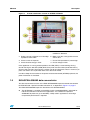
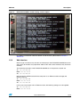
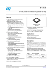
14. The demonstration board should run. Once an E-meter is found, the following screen
information should be shown (see Figure 9).
18/26
Doc ID 022957 Rev 1
UM1530
Figure 9.
Description
EVALSPEAr320HMI - board running, screen capture
For additional information about the SPEAr and all the tools, please refer to Section 2:
References.
1.5.3
Web interface
Even though a lot of data may be seen on the display of the EVALSPEAr320HMI board, the
web access to the data was prepared in order to view and access the data easily and more
remotely.
The network parameters of the EVALSPEAr320HMI set in the previous chapter are:
IP: 192.168.100.250
MASK: 255.255.255.0
GW: 192.168.100.252
Interconnect the SPEAr board with the computer via an Ethernet cable and apply the
following settings:
IP: 192.168.100.200
MASK: 255.255.255.0
GW: 192.168.100.250
In the case of connection with an Ethernet router, the following settings must be applied:
IP: 192.168.100.252
MASK: 255.255.255.0
Doc ID 022957 Rev 1
19/26
Description
UM1530
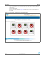
If the user would like to access the concentrator pages now, write the following address to
a web browser:
www:192.168.100.250/
After that, the screen depicted in Figure 10 should appear (in this case three meters are
connected).
Figure 10. User interface - evidence of the connected E-meters
20/26
Doc ID 022957 Rev 1
UM1530
Description
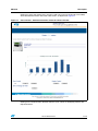
Clicking on one of the meters that is active (no red sign in front of the image of the meter)
shows detailed information about the meter status, as depicted in Figure 11.
Figure 11. User interface - detailed information about the chosen E-meter
Clicking on the action buttons (Breaker Control: Open, Close, for example) performs the
requested action.
Doc ID 022957 Rev 1
21/26
Description
1.5.4
UM1530
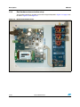
Real hardware demonstration setup
The complete application according to the block diagram depicted in Figure 2 on page 5 can
be seen in Figure 12 and Figure 13.
Figure 12. Real E-meter demonstrator
22/26
Doc ID 022957 Rev 1
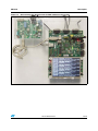
UM1530
Description
Figure 13. Real concentrator demonstrator (S-FSK modem on the top left)
Doc ID 022957 Rev 1
23/26
References
2
UM1530
References
●
DLMS:
–
●
ANDREA Informatique (DLMS/COSEM libraries)
–
●
●
●
24/26
www.dlms.com
www.andrea.fr
EVALSPEAr320HMI:
–
User manual UM1045 EVALSPEAr320HMI SPEAr320 board for HMI applications
–
SPEAr:
www.st.com/internet/mcu/subclass/1156.jsp
–
ST7570:
- EVALKITST7570-1 data brief
- AN3213 application note
- UM1008 user manual
STEVAL-IPP002V1:
–
STEVAL-IPP002V1 - IEC 61334-5-1 compliant smart meter system for AMI
applications based on STM32, ST7570 PLM, and STPMC1/STPMS1 chipset
–
FreeRTOS:
www.freertos.org
–
STM23F10xxx:
- STM32F10xxx datasheets
- STM32F10xxx reference manuals
- STM32F10xFWLib 3.1.2
–
Metering:
- UM0746 user manual
- STPMC1 datasheet
Product information
–
ST7570, refer to www.st.com\powerline
–
STM32, refer to www.st.com/mcu
–
STPMxx, refer to www.st.com\metering
–
ALTAIR, refer to www.st.com\metering.
Doc ID 022957 Rev 1
UM1530
3
Acronyms
Acronyms
Table 1.
List of acronyms
Abbreviation
Description
PLM
Power line modem
PLC
Power line communication
FSK
Frequency shift keying
Spread FSK
S-FSK
Human machine interface
HMI
STPMC1
ST power meter calculator type 1
STPMS2
STPM sensor type 2
Digital visualization panel
DVP
Device language message specification
DLMS
Companion specification for energy metering
COSEM
4
Revision history
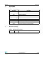
Table 2.
Document revision history
Date
Revision
30-Jul-2012
1
Changes
Initial release.
Doc ID 022957 Rev 1
25/26
UM1530
Please Read Carefully:
Information in this document is provided solely in connection with ST products. STMicroelectronics NV and its subsidiaries (“ST”) reserve the
right to make changes, corrections, modifications or improvements, to this document, and the products and services described herein at any
time, without notice.
All ST products are sold pursuant to ST’s terms and conditions of sale.
Purchasers are solely responsible for the choice, selection and use of the ST products and services described herein, and ST assumes no
liability whatsoever relating to the choice, selection or use of the ST products and services described herein.
No license, express or implied, by estoppel or otherwise, to any intellectual property rights is granted under this document. If any part of this
document refers to any third party products or services it shall not be deemed a license grant by ST for the use of such third party products
or services, or any intellectual property contained therein or considered as a warranty covering the use in any manner whatsoever of such
third party products or services or any intellectual property contained therein.
UNLESS OTHERWISE SET FORTH IN ST’S TERMS AND CONDITIONS OF SALE ST DISCLAIMS ANY EXPRESS OR IMPLIED
WARRANTY WITH RESPECT TO THE USE AND/OR SALE OF ST PRODUCTS INCLUDING WITHOUT LIMITATION IMPLIED
WARRANTIES OF MERCHANTABILITY, FITNESS FOR A PARTICULAR PURPOSE (AND THEIR EQUIVALENTS UNDER THE LAWS
OF ANY JURISDICTION), OR INFRINGEMENT OF ANY PATENT, COPYRIGHT OR OTHER INTELLECTUAL PROPERTY RIGHT.
UNLESS EXPRESSLY APPROVED IN WRITING BY TWO AUTHORIZED ST REPRESENTATIVES, ST PRODUCTS ARE NOT
RECOMMENDED, AUTHORIZED OR WARRANTED FOR USE IN MILITARY, AIR CRAFT, SPACE, LIFE SAVING, OR LIFE SUSTAINING
APPLICATIONS, NOR IN PRODUCTS OR SYSTEMS WHERE FAILURE OR MALFUNCTION MAY RESULT IN PERSONAL INJURY,
DEATH, OR SEVERE PROPERTY OR ENVIRONMENTAL DAMAGE. ST PRODUCTS WHICH ARE NOT SPECIFIED AS "AUTOMOTIVE
GRADE" MAY ONLY BE USED IN AUTOMOTIVE APPLICATIONS AT USER’S OWN RISK.
Resale of ST products with provisions different from the statements and/or technical features set forth in this document shall immediately void
any warranty granted by ST for the ST product or service described herein and shall not create or extend in any manner whatsoever, any
liability of ST.
ST and the ST logo are trademarks or registered trademarks of ST in various countries.
Information in this document supersedes and replaces all information previously supplied.
The ST logo is a registered trademark of STMicroelectronics. All other names are the property of their respective owners.
© 2012 STMicroelectronics - All rights reserved
STMicroelectronics group of companies
Australia - Belgium - Brazil - Canada - China - Czech Republic - Finland - France - Germany - Hong Kong - India - Israel - Italy - Japan Malaysia - Malta - Morocco - Philippines - Singapore - Spain - Sweden - Switzerland - United Kingdom - United States of America
www.st.com
26/26
Doc ID 022957 Rev 1