1
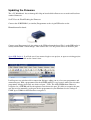
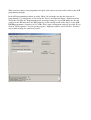
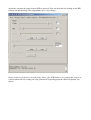
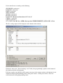
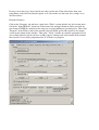
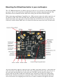
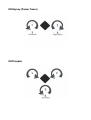
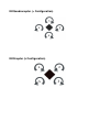
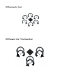
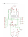
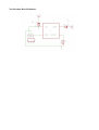
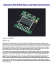
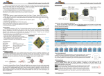
www.kkmulticopter.com
KKmulticontroller v.5.5 “Blackboard”
The Multicopter Flight Controller
Based on the original design by Rolf Bakke (KapteinKUK) with modifications by Jussi
Hermannsen and Mike Barton.
Table of Contents
Introduction to the KKmulticontroller..................................................................................................3
Flight Configurations ...........................................................................................................................3
Updating the Firmware.........................................................................................................................4
Mounting the KKmulticontroller in your multicopter..........................................................................9
KKOsprey (Power Tower)..................................................................................................................10
KKTricopter........................................................................................................................................10
KKQuadrocopter (+ Configuration)...................................................................................................11
KKXcopter (x Configuration).............................................................................................................11
KKSexycopter (Hex) ........................................................................................................................12
KKY6copter (Hex Y Configuration) .................................................................................................12
Setting up the KKmulticontroller.......................................................................................................13
Design Schematics for the v.5.5 SMD PCB.......................................................................................15
Introduction to the KKmulticontroller
The KKmulticontroller is a flight control board for remote control multicopters with 2,3,4 and 6
rotors. Its purpose is to stablise the aircraft during flight. To do this it takes the signal from the three
gyros on the board (roll, pitch and yaw) and feeds the information into the Integrated Circuit
(Atmega IC). This then processes the information according the the KK software and sends out a
control signal to the Electronic Speed Controllers (ESCs) which are plugged onto the board and also
connected to the motors. Depending upon the signal from the IC the ESCs will either speed up or
slow down the motors (and tilt the rear rotor with a servo in a Tricopter) in order to establish level
flight.
The board also takes a control signal from the Remote Control Receiver (RX) and feeds this into the
IC via the aileron, elevator, throttle and rudder pins on the board. After processing this information,
the IC will then send out a signal to the motors (Via the M1 to M6 pins on the board) to speed up or
slow down to achieve controlled flight (up, down, backwards, forwards, left, right, yaw) on the
command from the RC Pilot sent via his Transmitter (TX). In the case of a Tricopter, one of the pin
connectors (M4) will control a servo to achieve yaw authority.
The v.5.5 has an Atmega168 chip on board and an ISP header which gives users the option to tweak
and upload their own controller code.
Flight Configurations
The KKmulticontroller can be used in several different flight configurations depending upon which
firmware is loaded onto the chip.
These configurations are:
•
KKOsprey (2 Rotor)
•
KKTricopter (3 Rotor 1 servo)
•
KKQuadrocopter (4 Rotor + configuration)
•
KKXcopter (4 Rotor x configuration)
•
KKSexycopter (6 Rotor)
•
KKYcopter (6 Rotor Y configuration)
Updating the Firmware
The v.5.5 Blackboard has an Atmega168 chip on board which allows users to tweak and load non
standard firmware.
Set IC Fuses & Flash Flashing the Firmware
Connect the AVRISP Mk2 (or similar) Programmer to the six pin ISP header on the
Kkmulticontroller board.
Connect your Programmer's 6 pin socket to the ISP header on the board. Pin 1 on the ISP header is
usually marked with a small triangle. Then connect the a 5V DC power source to the PCB pins.
Open AVR Studio 4. It will ask you if you want to begin a new project, or open an existing project.
Choose Cancel and click on the connect icon.
It will open a new window with a connection dialogue asking you to select your programmer and
connection port. With a programmer like the AVRISP mkII it is easy because when you select that
programmer it brings back only one choice of port... USB. The AVR-ISP500 from Olimex is
recognised as a STK500 and has the option to auto choose the port. If it fails to recognise the port,
you may need to manually set the port for the programmer in your Windows device settings to
COM1 up to COM4 for AVR Studio to recognise it.
When you have chosen your programmer and port, click connect and you will be taken to the AVR
programming dialogue.
In the AVR programming window go to the "Main" tab and make sure that the chip you are
programming (e.g. Atmega168) is selected in the "Device and Signature Bytes" drop down menu.
Also make sure that the" Programming mode and target settings are set to ISP. Make sure that the
settings for the ISP mode have the ISP frequency set low enough to talk to the chip. I set my AVRISP500 programmer's frequency to 115.2 kHz. This is quite an important setting to get right. If you
click on "Read Signature" and you get the response "Signature matches selected device" you have
successfully managed to connect to your IC.
Also make sure that the target board or PCB is powered (You can check this by clicking on the HW
Settings tab and checking if the programmer can see any voltage).
Now it is time to set the fuses so click on the "Fuses" tab. AVR Studio is very good in this respect as
it will work out the fuse settings for your particular IC depending upon the check box options you
choose.
Set the check boxes according to the following.
SELFPRGEN: unchecked
RSTDISBL: unchecked
DWEN: unchecked
SPIEN: checked
WDTON: unchecked
EESAVE: unchecked
BODLEVEL: Brown-out detection at VCC=1.8 V
CKDIV8 : unchecked
CKOUT: unchecked
SUT_CKSEL: Int. RC Osc. 8 MHz; Start-up time PWRDWN/RESET: 6 CK/14 CK + 65 ms
The fuse setting output will be displayed at the bottom of the window.
Check the "Auto read" "Smart warnings" and "Verify after programming" options at the bottom of
the window and then click program.
If all goes to plan, you should get OK response messages in the output section at the bottom of your
window for Entering Programming mode, writing fuse address, reading fuse address, Fuse bits
verification and leaving programming mode.
If you get error messages, then recheck your chip version and all the connections from your
programmer to the board and that the power is on. Also make sure that your fuse settings are as
described above.
Flash the Firmware
Click on the "Program" tab and have a look at the "Flash" section which is the 2nd section down.
Check the "Input HEX file" check box. Then browse the unzipped firmware folder and click on
your firmware HEX file suitable for the chip you are programming for an Atmega168. Then click
"Program" in the Flash section of the window and you should get an OK response in the output
section at the bottom of the window. Then click "Verify" to make sure that the program has been
successfully uploaded and if you have an OK response coming back at the bottom of the window
then you have successfully programmed the IC with the test program.
Mounting the KKmulticontroller in your multicopter.
The v.5.5 KKmutlicontroller uses Murata piezo gyros that are less sensitive to vibration than SMD
type gyros, but it is still a good idea to mount the board on a vibration dampening material. The
board must also be mounted with the white arrow facing the direction of forward flight.
When connecting your Remote Control Receiver (RX) you must connect the white signal wire of
the channels (CH1, CH2, CH3 and CH4) from your RX corresponding to the aileron, elevator,
throttle and rudder to the inner pins on the board while the red (VCC) wires are connected to the
center pins, and the black (GND) wires are connected to the pins on the outer edge of your board.
The pins marked M1 to M6 are connected to the 3 pin BEC plug from your ESCs. They follow the
same convention as the RX pins with the white wires connected to the inner pins, the red wires to
the center pins and the black wires to the outer pins. The ESCs and the connected motors are
plugged onto the pins M1 to M6 in the following order depending on flight rotor configuration.
Note also the direction of rotation for each motor. This is achieved by connecting the three ESC
wires to the motors and swapping two of the wires to achieve rotation in the opposite direction.
KKOsprey (Power Tower)
KKTricopter
KKQuadrocopter (+ Configuration)
KKXcopter (x Configuration)
KKSexycopter (Hex)
KKY6copter (Hex Y Configuration)
Setting up the KKmulticontroller
1.Checking transmitter channels:
-Take off the propellers.
-Turn on transmitter and flight controller.
-Set throttle to about 1/4. Motors should start.
-Move pitch (elevator) stick forward. Back motor should speed up. If not, reverse pitch (elevator)
channel.
-Move roll (aileron) stick to the left. Right motor should speed up. If not, reverse roll (aileron)
channel.
-Move yaw (rudder) stick to the left. Front and back motor should speed up. If not, reverse yaw
(rudder) channel.
2. Transmitter throttle adjustiment:
- Turn on transmitter and flight controller.
- If led does not turn on and stays on, lower your trim.
- If still no go, you may need to reverse the throttle channel.
- On Tri v1.5 and Quad v4.5 firmware and above, you need to Arm your board by putting the left
stick down and to the right for the LED to come on. If this does not happen, adjust your throttle and
yaw trim down and to the right on your transmitter. Make sure you do not have any mixing switches
on your Transmitter enabled.
3. Initial transmitter ATV/servo range settings:
- Pitch (elevator): 50%
- Roll (aileron): 50%
- Yaw (rudder): 100%
4. ESC throttle range:
- Turn yaw pot to zero.
- Turn on transmitter.
- Throttle stick to full.
- Turn on flight controller.
- Wait until the ESCs beep twice after the initial beeps. (Plush and SS ESC's)
- Throttle stick to off. ESCs beep.
- Turn off flight controller.
- Restore the yaw pot.
5. Initial Gyro gain pot value is 50%. Increase until it starts to oscillate rapidly, then back off until it
is stable again. Fast forward flight needs lower gain.
Too low gain is recognized by the multicopter being hard to control and/or always wanting to tip
over.
6. Checking gyro directions:
- Take off the propellers.
- Turn on transmitter and flight controller.
- Set throttle to about 1/4. Motors should start.
- Tilt multicopter forward. Forward motor should speed up. If not, reverse pitch gyro.
- Tilt multicopter to the left. Left motor should speed up. If not, reverse roll gyro.
- Turn multicopter CW. Front and back motor should speed up. If not, reverse yaw gyro.
7. Reversing gyros:
- Set roll gain pot to zero.
- Turn on flight controller.
- LED flashes rapidly 10 times.
- Move the stick for the gyro you want to reverse.
- LED will blink continually.
- Turn off flight controller.
- If there is more gyros to be reversed, goto step 2, else set roll gain pot back.
8.Final check:
Hold the multicopter firmly over our head and slowly advance to about 1/2 throttle. Hold it steady
when you start increasing the throttle, becouse the multicontroller calibrates its gyros when throttle
leaves zero, and then the gyros need to be at rest.
If the multicopter tries to twist away, check propeller and motor directions, gyro placement and trim
settings. A slight twist is OK.
If not, try to twist the quad. It should resist your movements. More gyro gain gives more resistance.
If it starts to oscillate, reduce the gain. You should not need to reduce the gain below 40%.
Note: the correct procedure for taking off from the ground is as following:
1: The quad and its propellers needs to be motionless.
2: Increase the throttle (collective). Just as the throttle leaves zero, gyro calibration is performed.
3: Enjoy! And remember to close the throttle if you lose control. Much less damage.
NOTES: Do not use bigger propellers than you need. Light propellers gives faster response and
more stability.Try to get it to hover at about midstick (1/3 to 2/3 throttle). Use smaller/bigger
propeller, different motor Kv or more/less Battery cells to achieve that.
Design Schematics for the v.5.5 SMD PCB
Yaw Breakout Board Schematic