1
PIATTAFORME AEREE SEMOVENTI
SELF-PROPELLED WORK-PLATFORMS
PLATES-FORMES DE TRAVAIL AUTOMOTRICES
SELBSTFAHRENDE HUBARBEITSBÜHNEN
PLATAFORMAS ELEVADORAS AUTOPROPULSADAS
ZELFRIJDENDE HOOGWERKERS
SJÄLVGÅENDE ARBETSPLATTFORMAR
SAMOKRETNE RADNE PLATFORME
ÖNHAJTÁSÚ MUNKAÁLLVÁNYOK
„XL“ SERIES
XL11 XL14 XL16 XL19
USE AND MAINTENANCE MANUAL
- ENGLISH – ORIGINAL INSTRUCTIONS
AIRO is a division of TIGIEFFE SRL
Via Villasuperiore , 82 - 42045 Luzzara (RE) ITALY ' +39-0522-977365 7 +39-0522-977015
WEB: www.airo.it
027.20.UEM-EN
2010-01
Revision date
01-2010
•
•
Description of revision
Update for new machine directive 2006/42/EC.
Model name update.
Use and Maintenance Manual - XL Series
Page 2
Tigieffe thanks you for purchasing a product of its range, and invites you to read this manual. Here you can find all the necessary
information for a correct use of the purchased machine; therefore, you are advised to follow the instructions carefully and to read
the manual thoroughly. The manual should be kept in a suitable place where no damage can occur to it. The content of this manual
may be modified without prior notice and further obligations in order to add changes and improvements to the units already
delivered. No reproduction or translation may take place without the written permission of the owner.
Contents:
1. INTRODUCTION ............................................................................................................................................................................ 6
1.1 Legal aspects ..............................................................................................................................................................................6
1.1.1 Delivery of the machine............................................................................................................................................................6
1.1.2 Declaration of commissioning, first check, further periodical checks and transfers of ownership ............................................6
1.1.2.1 Declaration of commissioning and first check .......................................................................................................................6
1.1.2.2 Further periodical checks ......................................................................................................................................................7
1.1.2.3 Transfers of ownership..........................................................................................................................................................7
1.1.3 Operator training and information ............................................................................................................................................7
1.2 Tests performed before delivery .................................................................................................................................................7
1.3 Intended use ...............................................................................................................................................................................7
1.4 Description of the machine..........................................................................................................................................................8
1.5 Control panels .............................................................................................................................................................................8
1.6 Drive power .................................................................................................................................................................................9
1.7 Machine life, demolition and decommissioning ...........................................................................................................................9
1.8 Identification ..............................................................................................................................................................................10
1.9 Location of main components ...................................................................................................................................................11
2. TECHNICAL FEATURES OF STANDARD MACHINES ............................................................................................................. 12
2.1 Model XL11 E............................................................................................................................................................................12
2.2 Model XL14 E............................................................................................................................................................................14
2.3 Model XXL14 E .........................................................................................................................................................................16
2.4 Model XL14 RTD.......................................................................................................................................................................18
2.5 Model XL16 E............................................................................................................................................................................20
2.6 Model XXL16 E .........................................................................................................................................................................22
2.7 Model XL16 RTD.......................................................................................................................................................................24
2.8 Model XL19 E............................................................................................................................................................................26
2.9 Model XL19 RTD.......................................................................................................................................................................28
2.10 Vibrations and noise................................................................................................................................................................30
3. SAFETY PRECAUTIONS ............................................................................................................................................................ 31
3.1 Individual protection devices (IPD). ...........................................................................................................................................31
3.2 General safety norms ................................................................................................................................................................31
3.3 Intended use .............................................................................................................................................................................32
3.3.1 General ..................................................................................................................................................................................32
3.3.2 Handling .................................................................................................................................................................................32
3.3.3 Operating procedures ............................................................................................................................................................33
3.3.4 Wind speed according to BEAUFORT SCALE ......................................................................................................................34
3.3.5 Pressure of the machine on ground and load-bearing capacity of ground .............................................................................35
3.3.6 High-voltage lines...................................................................................................................................................................36
3.4 Hazardous situations and/or accidents .....................................................................................................................................36
4. INSTALLATION AND PRELIMINARY CHECKS......................................................................................................................... 37
4.1 Becoming acquainted with the machine ....................................................................................................................................37
4.2 Preliminary operation checks ....................................................................................................................................................37
5. USE INSTRUCTIONS .................................................................................................................................................................. 38
5.1 Platform control panel ...............................................................................................................................................................38
5.1.1 Drive and steering ..................................................................................................................................................................40
5.1.2 Drive with operator on the ground ..........................................................................................................................................41
5.1.3 Platform positioning................................................................................................................................................................41
5.1.3.1 Platform lifting/lowering .......................................................................................................................................................41
Use and Maintenance Manual - XL Series
Page 3
5.1.3.2 Platform extraction/retraction (optional) ..............................................................................................................................42
5.1.3.2.1 Sliding platform extraction/retraction (optional) ................................................................................................................42
5.1.3.2.2 Extension deck extraction/retraction (optional) ................................................................................................................42
5.1.4 Levelling outriggers control (OPTIONAL) ...............................................................................................................................43
5.1.4.1 Levelling outriggers manual control (OPTIONAL) ...............................................................................................................43
5.1.4.2 Levelling outriggers manual control (OPTIONAL) ...............................................................................................................43
5.1.5 Other functions of the platform control panel .........................................................................................................................45
5.1.5.1 Selection of electric/thermic propulsion (OPTIONAL) .........................................................................................................45
5.1.5.2 Electrical pump start/stop button (OPTIONAL) ...................................................................................................................45
5.1.5.3 Heat engine starting switch (models” D”, “ED”, “B”, EB”) ....................................................................................................45
5.1.5.4 Manual horn ........................................................................................................................................................................45
5.1.5.5 Emergency stop button .......................................................................................................................................................45
5.1.5.6 Warning lights .....................................................................................................................................................................46
5.1.5.6.1 Enabled control panel green warning light (O) .................................................................................................................46
5.1.5.6.2 Sliding platform position green warning light (P - only for machines with sliding platform) ..............................................46
5.1.5.6.3 Flat battery red warning light (Q – only Electric and Electro/diesel models) ....................................................................46
5.1.5.6.4 Drive enable green warning light (R) ................................................................................................................................46
5.1.5.6.5 Danger red warning light (S) ............................................................................................................................................46
5.1.5.6.6 Lifting enable green warning light (T) ...............................................................................................................................47
5.1.5.6.7 Overload red warning light (U) .........................................................................................................................................47
5.1.5.6.8 Diesel engine fault / low fuel red warning light (V) ...........................................................................................................47
5.2 Ground control panel and electric control unit ...........................................................................................................................48
5.2.1 On-off key and control panel selector (A) ...............................................................................................................................49
5.2.2 Emergency STOP button (B) .................................................................................................................................................49
5.2.3 Diesel/electric power selector (C)..........................................................................................................................................49
5.2.4 Heat engine starting switch (D) ..............................................................................................................................................49
5.2.5 User interface display (E) .......................................................................................................................................................50
5.2.6 Battery charger warning light (F) ............................................................................................................................................50
5.2.7 Enabled control panel warning light (G) .................................................................................................................................50
5.2.8 Diesel engine warning lights (G-H-L-M-N) .............................................................................................................................50
5.2.9 Platform control levers (O-P-Q-R) ..........................................................................................................................................50
5.3 Platform access.........................................................................................................................................................................51
5.4 Start-up .....................................................................................................................................................................................51
5.4.1 Heat engine start-up...............................................................................................................................................................52
5.4.2 Starting the 230V single-phase electrical pump (OPTIONAL)................................................................................................52
5.4.3 Starting the 380V three-phase electrical pump (OPTIONAL) .................................................................................................53
5.5 Machine stop .............................................................................................................................................................................54
5.5.1 Normal stop ............................................................................................................................................................................54
5.5.2 Emergency stop .....................................................................................................................................................................54
5.5.3 Diesel engine stop..................................................................................................................................................................54
5.5.4 Stopping the 380V three-phase or 230V single-phase electrical pump (optional)..................................................................55
5.6 Emergency manual pump .........................................................................................................................................................55
5.6.1 Platform emergency lowering.................................................................................................................................................56
5.6.2 Other emergency operations..................................................................................................................................................56
5.7 Socket for electric tool connection (optional).............................................................................................................................57
5.8 Fuel level and re-fuelling (models “ED”, “D”) .............................................................................................................................57
5.9 End of work ...............................................................................................................................................................................58
6. HANDLING AND CARRYING ...................................................................................................................................................... 59
6.1 Handling ....................................................................................................................................................................................59
6.2 Carrying ....................................................................................................................................................................................60
6.2.1 Fold-down rails .......................................................................................................................................................................62
6.3 Emergency towing.....................................................................................................................................................................63
7. MAINTENANCE ........................................................................................................................................................................... 64
7.1 Safety lock for maintenance operations ....................................................................................................................................65
7.2 Machine cleaning ......................................................................................................................................................................65
7.3 General maintenance ................................................................................................................................................................66
7.3.1 Various adjustments...............................................................................................................................................................67
7.3.2 Greasing ................................................................................................................................................................................68
Use and Maintenance Manual - XL Series
Page 4
7.3.3 Hydraulic circuit oil level check and change ...........................................................................................................................69
7.3.4 Hydraulic filter replacement....................................................................................................................................................70
7.3.4.1 Suction filters.......................................................................................................................................................................70
7.3.4.2 Return filter (XXL14 D - XL14 RTD - XL16 E – XL16 RTD - XL19 E – XL19 RTD).............................................................71
7.3.5 Drive reduction gear oil level check and change ....................................................................................................................72
7.3.6 Air purging from oscillating axle locking cylinders ..................................................................................................................73
7.3.7 Pressure relief valve adjustment and operation check ...........................................................................................................74
7.3.8 Lifting circuit pressure relief valve adjustment........................................................................................................................75
7.3.9 Braking system efficiency check ............................................................................................................................................76
7.3.10 Slide-out extension deck clearance adjustment ...................................................................................................................77
7.3.11 Inclinometer operation check ...............................................................................................................................................78
7.3.12 Operation check and adjustment of platform overload controller .........................................................................................79
7.3.13 Overload controller by-pass – ONLY FOR EMERGENCY OPERATIONS ..........................................................................80
7.3.14 Operation check of safety microswitches .............................................................................................................................81
7.3.14.1 Microswitch M1 .................................................................................................................................................................81
7.3.14.2 Microswitch M1S (if available) ...........................................................................................................................................81
7.3.14.3 Microswitch M3 (OPTIONAL) ............................................................................................................................................81
7.3.14.4 Microswitches M5A-M5B (if available) ..............................................................................................................................81
7.3.14.4.1 Microswitch M5A-M5B for machines with sliding platform..............................................................................................81
7.3.14.4.2 Microswitches M5A and M5B for machines with dual slide-out extension deck (if available).........................................81
7.3.14.5 Microswitches ST1A-ST1B-ST1C-ST1D (machines with levelling outriggers) ..................................................................82
7.3.14.6 Microswitches STP1-STP2-STP3-STP4 (machines with levelling outriggers) ..................................................................82
7.3.15 Dead-man safety system operation check ...........................................................................................................................83
7.3.15.1 Dead-man pedal................................................................................................................................................................83
7.3.15.2 Dead-man button ..............................................................................................................................................................83
7.4 Starter battery ...........................................................................................................................................................................84
7.4.1 Starter battery models “D” “ED” .............................................................................................................................................84
7.4.2 Starter type battery for models “E” .........................................................................................................................................84
7.4.3 Starter battery maintenance ...................................................................................................................................................84
7.4.4 Starter battery recharge .........................................................................................................................................................84
7.5 “DRIVE” battery for models “E” and “ED” ..................................................................................................................................85
7.5.1 General instructions for DRIVE battery ..................................................................................................................................85
7.5.2 DRIVE battery maintenance...................................................................................................................................................85
7.5.3 DRIVE battery recharge .........................................................................................................................................................86
7.5.4 Battery charger: fault report ...................................................................................................................................................87
7.5.5 Battery replacement ...............................................................................................................................................................87
8 . MARKS AND CERTIFICATIONS................................................................................................................................................. 88
9. PLATES AND STICKERS ........................................................................................................................................................... 89
10. CHECK REGISTER ..................................................................................................................................................................... 92
Annexes:
Hydraulic and electric circuit diagrams
Check register
Declarations of conformity
Use and Maintenance Manual - XL Series
Page 5
1. INTRODUCTION
This Use and Maintenance Manual provides general instructions concerning the complete range of machines indicated on the
cover. Therefore the description of their components, as well as control and safety systems, may include parts not present on your
machine since supplied on request or not available. In order to keep pace with the technical development AIRO-Tigieffe s.r.l. the
right to modify the product and/or the use and maintenance manual at any time without updating the units already delivered.
1.1
Legal aspects
1.1.1
Delivery of the machine
Within EU (European Union) member countries the machine is delivered complete with:
§ Use and Maintenance manual in your language
§ CE mark applied on the machine
§ Original EC declaration of conformity
§ Guarantee certificate
Only for Italy:
§ Declaration of commissioning to ISPESL
§ List of local ISPESL departments
§ Declaration of internal testing
It is to be noted that the Use and Maintenance Manual is an integral part of the machine and a copy of this, together with copies of
the documents certifying that the periodical checks have been carried out, must be kept on board in its suitable container. In the
event of a transfer of property the machine must always be provided with its use and maintenance manual.
1.1.2
Declaration of commissioning, first check, further periodical checks and transfers of ownership
The legal obligations of the owner of the machine vary according to the country of commissioning. It is therefore recommended to
inquiry about the procedures in force in your country from the boards responsible for industrial safety. This manual contains a final
section called "Check register" for a better filing of documents and recording of any modifications.
1.1.2.1 Declaration of commissioning and first check
In ITALY the owner of the Aerial Platform must notify the use of the machine to the local competent ISPESL (National Institute for
the prevention of accidents at the workplace) and submit it to periodical compulsory checks. The first one of these checks is carried
out by ISPESL, while the following ones by the territorial inspection boards (ASL/USL or ARPA). The checks are on a payment
basis and the machine owner will be charged for them. For these checks, the territorial inspection boards (ASL/USL or ARPA) and
ISPESL can be supported by authorized public or private subjects. The authorized private subjects acquire the qualification of
responsibles of the public service and refer directly to the public structure that controls this function.
To declare the commissioning of the machine in Italy, send the form that is supplied together with other documents upon machine
delivery, by registered letter with advice of receipt.
ISPESL will assign a Serial Number and during the First Check will issue a "Check booklet" indicating only the detectable data of
the machine already in use or inferable from the relative User Manual. Afterwards ISPESL will send a copy of the same booklet to
the territorial inspection boards (ASL/USL or ARPA) which will carry out the further periodical mandatory checks (every year).
Use and Maintenance Manual - XL Series
Page 6
1.1.2.2 Further periodical checks
Yearly checks are compulsory. In Italy the owner of the Aerial Platform must apply for a periodical check by sending a registered
letter to the local competent inspection board (ASL/USL or ARPA) at least twenty days before the expiry of the year from the last
check.
Note: If a machine without a valid control document should be moved in an area outside the competence of the usual inspection
board, the owner of the machine must ask the inspection board, competent for the new territory where the machine is to be used,
for the yearly check.
1.1.2.3 Transfers of ownership
In case of transfer of ownership (in Italy) the new owner of the Aerial Platform must notify the ownership of the machine to the local
competent inspection board (ASL/USL or ARPA) by enclosing a copy of:
§ Declaration of conformity issued by the manufacturer
§ Declaration of commissioning carried out by the first owner
1.1.3
Operator training and information
The employer must ensure that the workers appointed to use the equipment are adequately and specifically trained so they are
able to use the Elevating Work Platform in a proper and safe way and also avoid the risks caused by other people.
1.2
Tests performed before delivery
Before being placed on the market, each EWP undergoes the following tests:
§ Braking test
§ Overload test
§ Operating test
1.3
Intended use
The machine described in this use and maintenance manual is a self-propelled aerial platform intended for lifting persons and
materials (equipment and building materials) in order to carry out maintenance, installation, cleaning, painting, de-painting, sandblasting, welding operations, etc.
The max. capacity allowed (which varies according to the model – see paragraph “Technical features”) is divided as follows:
§ 80 Kg for each person on board
§ 40 Kg for equipment
§ any remaining load is represented by the material being worked.
In any case NEVER exceed the maximum capacity allowed as indicated in paragraph "Technical features”. Persons, tools and
building materials can be loaded on the platform only from the access position (platform lowered). It is absolutely forbidden to load
persons, tools and building materials on the platform when it is not in access position.
All loads must be positioned inside the platform. Do not lift loads (even if complying with the maximum capacity allowed) hanging
from the platform or lifting structure.
Do not carry large-sized panels since they increase the resistance to wind force thus causing the machine to overturn.
While the machine is being displaced with lifted platform, no horizontal loads can be loaded onto the platform (operators on board
are not allowed to pull wires or ropes, etc.).
An overload controller stops the operation of the machine if the load on the platform exceeds by 30% approx. the rated load (see
chapter "General use rules”) and platform is lifted.
The machine cannot be used in areas where road vehicles operate. Always surround the working area by means of suitable signs
when the machine is used in public areas.
Do not use the machine to tow trucks or other vehicles.
All types of machine use other than those for which it was designed must be approved in writing by the machine manufacturer
following a specific request on the part of the user.
Use and Maintenance Manual - XL Series
Page 7
Do not use the machine for purposes other than those for which it was designed, except after making a
request and having obtained written permission in this sense from the manufacturer.
1.4
Description of the machine
The machine described in this use and maintenance manual is a self-propelled lifting platform equipped with:
§ motorised chassis equipped with wheels and, on request, with levelling outriggers (optional);
§ vertical scissor lift structure operated by one or more hydraulic cylinders (the number of cylinders varies according to machine
model)
§ operator platform which can be of two types(the max. capacity varies according to the model - see chapter "Technical
features”).
o Manual extension in both directions.
o Hydraulic extension in both directions.
The chassis is motorised to allow the machine to move (see "General use instructions"). On 2 wheel drive models the chassis is
equipped with two rear driving wheels and two front idle steering wheels. On 4 wheel drive models the chassis is equipped with two
rear driving wheels and two front driving and steering wheels. All driving wheels are equipped with hydraulic parking brakes,
positive logic type (when drive controls are released brakes are automatically activated). On request the machine may be equipped
with levelling outriggers to operate on inclined grounds (but sufficiently firm). Even in this case the machine is enough steady to
operate on horizontal and sufficiently firm grounds and the platform can be lifted with the chassis resting on the four puncture-proof
tires without using the levelling outriggers. These must be used when operating on uneven but sufficiently firm grounds. The
levelling outriggers are controlled from the platform control panel, where machine levelling and operations in progress can be
checked by means of a spirit level. The machine is also equipped with an inclinometer, a device that stops lifting in the event that
the platform is lifted at a height from the ground which varies from model to model (the stability limits of each model are indicated in
paragraph "Technical Features").
The hydraulic cylinders which move the articulated structure and the levelling outriggers are provided with solenoid valves or safety
valves directly flanged on the same. This enables the machine to be held in position also in the event of an accidental breaking of
the supply pipe.
The platform can be of two types:
§ The fixed platform is fitted with two manual slide-out extension decks which extend the operator’s work surface.
§ The fixed platform is fitted with two hydraulic slide-out extension decks which extend the operator’s work surface.
In any case, the platform is equipped with guard-rails and toe-boards of a prescribed height (the height of the guard-rails is ≥ 1100
mm; the height of the toe-boards is ≥150 mm).
When no motive power is available, the manual emergency lowering can be controlled by means of the manual pump and knob
indicated by the instructions plates.
1.5
Control panels
The machine is equipped with two control panels:
§ On the platform for normal use of the machine.
§ On the chassis you can find: the emergency controls to lower or stop the platform and the emergency stop button, a keyselector to select the control panel and to start the machine.
Use and Maintenance Manual - XL Series
Page 8
1.6
Drive power
The machines can be powered by:
§ an electric-hydraulic system composed of rechargeable accumulators and electrical pump;
§ a heat engine (Diesel engine models are identified by the abbreviation “D”; petrol engine models are identified by the
abbreviation “B”);
§ a dual propulsion electric/thermic system (dual propulsion Electric/Diesel models are identified by the abbreviation “ED”; dual
propulsion Electric/Petrol models are identified by the abbreviation “EB”).
In any case both the hydraulic and the electric systems are equipped with all necessary protections (see electric and hydraulic
circuit diagrams annexed to this manual).
1.7
Machine life, demolition and decommissioning
The machine has been designed to last for 10 years in normal operating environments, if properly used and serviced. Within this
period, the manufacturer must carry out a complete inspection/overhaul.
If disposal of the machine is necessary, comply with current local regulations.
In Italy, the demolition/decommissioning must be notified to the local ASL / USL or ARPA.
The machine consists mainly of metal parts which are easy to be identified (steel for the most parts, and aluminium for the
hydraulic blocks); thus, we can state that the machine can be recycled at 90%.
European standards and those transposed by the member countries relating to respect for the environment
and the disposal of wastes envisage heavy administrative and penal fines in case of infringement.
In case of demolition/decommissioning, carefully keep to the provisions of applicable regulations,
especially as regards materials such as hydraulic fluids and batteries.
Use and Maintenance Manual - XL Series
Page 9
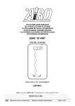
1.8
Identification
In order to identify the machine, when spare parts and service are required, always mention the information given in the serial
number plate. Should this plate (as well as the various stickers applied on the machine) be lost or illegible, it is to be replaced as
soon as possible. In order to identify the machine when no plate is available the serial number is also stamped on the chassis. To
locate the plate and the stamp of the serial number, see the following picture. It is recommended to copy such data in the following
boxes.
MODEL: _________________
CHASSIS: __________________ YEAR: __________________
Fig. 1
Use and Maintenance Manual - XL Series
Page 10
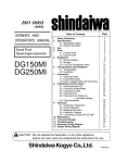
1.9
Location of main components
The picture shows the machine and
its own components.
8
14
14
14
(4)
10.11
9.15
4
1
7
7
6
2
1) Control panel
2) Electric control unit (ground
controls)
3) Hydraulic control unit
4) Hydraulic drive motors
5) Drive control hydraulic
assembly (drive plate)
6) 230V plug (optional)
7) Spirit level (standard for
models with levelling
outriggers; optional for the
other models) for visual check
of machine levelling
8) Lifting cylinders
9) Battery
10) Power steering
11) Inclinometer
12) Control device for electric
system isolation (electric
machines E )
13) Emergency manual pump
14) Levelling outriggers (optional)
15) Heat engine (models “ED”, “D”,
EB”)
16) Pump 230V/380V (option only
on models "D" and "ED")
17) 230V/ 380V socket and
switches (optional only on
models D and E/D)
18) 230V/380V electric control unit
for pump control (optional on
models D and ED)
3,12,13
5
Use and Maintenance Manual - XL Series
Page 11
2. TECHNICAL FEATURES OF STANDARD MACHINES
THE TECHNICAL FEATURES OF THE PRODUCTS IN THE FOLLOWING PAGES CAN BE MODIFIED
WITHOUT PRIOR NOTICE
2.1 Model XL11 E
XL11 E
Dimensions:
Maximum working height
Maximum platform height
Ground clearance
Platform height for safety speed activation
Internal steering radius
External steering radius
Maximum capacity (m)
Max. number of people on the platform (n) – indoors
Tool and material weight (me) (**) – indoors
Max. number of people on the platform (n) – outdoors
Tool and material weight (me) (**) – outdoors
Maximum deck extension
Maximum capacity with platform extended
Max. No. of people with platform extended
Maximum drive height
Maximum dimensions with platform extended
Max. hydraulic pressure
Max. pressure of lifting circuit
Min. pressure of braking circuit
Tyre dimensions (****)
Tyre type (****)
Transport dimensions with removable rails installed
Transport dimensions with removable rails not installed
Transport dimensions with rails folded down
Machine weight (unloaded) (*)
Stability limit:
Longitudinal inclination
Transversal inclination
Maximum wind speed (***)
Max. load per wheel
Performance:
Driving wheels
Max. drive speed
Safety drive speed
Lowering/lifting time (unloaded)
Tank oil capacity
Gradeability
Max. operating temperature
Min. operating temperature
Battery power:
Voltage and capacity of battery
Battery weight
Single-phase battery charger (HF)
Max. current absorbed by battery charger
Max. installed power
Power electrical pump 1
Max. absorbed current
Power electrical pump 2
Max. absorbed current
Power electrical pump 3
Max. absorbed current
Use and Maintenance Manual - XL Series
11.2
9.2
255
2
3.3
5.8
700
3
460
3
460
1.17 + 1.17
700
3
Max
1.74 x 5.835
210
140
50 ÷ 60
Ø 730 x 265
10 x 16.5
3.75 x 1.8 x 2.53
N.A.
3.75 x 1.8 x 1.81
4850
m
m
mm
m
m
m
Kg
3
2
12.5
1940
°
°
m/s
Kg
2
4
0.36
85 / 80
40
25
+50
-15
N
km/h
km/h
Sec.
Lt.
%
C
C
2 x 24 / 325
2 x 220
48 / 45
15
4.5
4.5
160
NA
NA
NA
NA
V/Ah
Kg
V/A
A
kW
kW
A
kW
A
kW
A
Kg
Kg
m
Kg
m
Bar
Bar
Bar
mm
m
m
m
Kg
Page 12
Diesel Power
Diesel engine type
Engine power
Starter battery
Tank oil capacity
NA
NA
NA
NA
kW
V/Ah
Lt.
380V three-phase electrical pump (optional)
Engine power
Max. absorbed current
Max. drive speed
NA
NA
NA
kW
A
km/h
(*) In some cases different limits can be fixed. It is recommended to comply with the data shown on the machine plate.
( ** ) me = m – (n x 80)
(***) Wind speeds higher or equal to 12.5 m/s indicate that the machines can also be used outdoors; Wind speeds equal to 0 m/s
indicate that the machines can be used INDOORS ONLY. For XL11E it is possible to increase the max. allowed wind speed to 17
m/s by placing a ballast on the chassis of 300 kg.
(****) Standard: tyres filled with puncture-proof polyurethane foam; Optional: extra flexible black tyres 250-15; Optional: extra flexible no-marking
tyres 250-15.
Use and Maintenance Manual - XL Series
Page 13
2.2
Model XL14 E
XL14 E
Dimensions:
Maximum working height
Maximum platform height
Ground clearance
Platform height for safety speed activation
Internal steering radius
External steering radius
Maximum capacity (m)
Max. number of people on the platform (n) – indoors
Tool and material weight (me) (**) – indoors
Max. number of people on the platform (n) – outdoors
Tool and material weight (me) (**) – outdoors
Maximum deck extension
Maximum capacity with platform extended
Max. No. of people with platform extended
Maximum drive height
Maximum dimensions with platform extended
Max. hydraulic pressure
Max. pressure of lifting circuit
Min. pressure of braking circuit
Tyre dimensions (****)
Tyre type (****)
Transport dimensions with removable rails installed
Transport dimensions with removable rails not installed
Transport dimensions with rails folded down
Machine weight (unloaded) (*)
Stability limit:
Longitudinal inclination
Transversal inclination
Maximum wind speed (***)
Max. load per wheel
Performance:
Driving wheels
Max. drive speed
Safety drive speed
Lowering/lifting time (unloaded)
Tank oil capacity
Gradeability
Max. operating temperature
Min. operating temperature
Battery power:
Voltage and capacity of battery
Battery weight
Single-phase battery charger (HF)
Max. current absorbed by battery charger
Max. installed power
Power electrical pump 1
Max. absorbed current
Power electrical pump 2
Max. absorbed current
Power electrical pump 3
Max. absorbed current
Use and Maintenance Manual - XL Series
13.8
11.8
255
2.3
3.3
5.8
500
3
260
3
260
1.17 + 1.17
500
3
8
1.74 x 5.835
210
180
50 ÷ 60
Ø 730 x 265
10 x 16.5
3.75 x 1.8 x 2.73
N.A.
3.75 x 1.8 x 2.01
5150
m
m
mm
m
m
m
kg
3
2
12.5
2060
°
°
m/s
Kg
2
4
0.36
85 / 80
40
22
+50
-15
n
km/h
km/h
Sec.
Lt.
%
C
C
2 x 24 / 325
2 x 220
48 / 45
15
4.5
4.5
160
NA
NA
NA
NA
V/Ah
kg
V/A
A
kW
kW
A
kW
A
kW
A
kg
kg
m
kg
m
m
bar
bar
bar
mm
m
m
m
kg
Page 14
Diesel Power
Diesel engine type
Engine power
Starter battery
Diesel oil tank capacity
NA
NA
NA
NA
kW
V/Ah
Lt.
380V three-phase electrical pump (optional)
Engine power
Max. absorbed current
Max. drive speed
NA
NA
NA
kW
A
km/h
(*) In some cases different limits can be fixed. It is recommended to comply with the data shown on the machine plate.
( ** ) me = m – (n x 80)
(***) Wind speeds higher or equal to 12.5 m/s indicate that the machines can also be used outdoors; Wind speeds equal to 0 m/s
indicate that the machines can be used INDOORS ONLY.
(****) Standard: tyres filled with puncture-proof polyurethane foam; Optional: extra flexible black tyres 250-15; Optional: extra flexible no-marking
tyres 250-15.
Use and Maintenance Manual - XL Series
Page 15
2.3
Model XXL14 E
XXL14 E
Dimensions:
Maximum working height
Maximum platform height
Ground clearance
Platform height for safety speed activation
Internal steering radius
External steering radius
Maximum capacity (m)
Max. number of people on the platform (n) – indoors
Tool and material weight (me) (**) – indoors
Max. number of people on the platform (n) – outdoors
Tool and material weight (me) (**) – outdoors
Maximum deck extension
Maximum capacity with platform extended
Max. No. of people with platform extended
Maximum drive height
Maximum dimensions with platform extended
Max. hydraulic pressure
Max. pressure of lifting circuit
Min. pressure of braking circuit
Tyre dimensions (****)
Tyre type (****)
Transport dimensions with removable rails installed
Transport dimensions with removable rails not installed
Transport dimensions with rails folded down
Machine weight (unloaded) (*)
Stability limit:
Longitudinal inclination
Transversal inclination
Maximum wind speed (***)
Max. load per wheel
Performance:
Driving wheels
Max. drive speed
Safety drive speed
Lowering/lifting time (unloaded)
Tank oil capacity
Gradeability
Max. operating temperature
Min. operating temperature
Battery power:
Voltage and capacity of battery
Battery weight
Single-phase battery charger (HF)
Max. current absorbed by battery charger
Max. installed power
Power electrical pump 1
Max. absorbed current
Power electrical pump 2
Max. absorbed current
Power electrical pump 3
Max. absorbed current
Use and Maintenance Manual - XL Series
13.8
11.8
255
2.3
3.3
5.8
500
3
260
3
260
1.17 + 1.17
500
3
8
1.74 x 5.835
210
180
50 ÷ 60
Ø 730 x 265
10 x 16.5
3.84 x 1.8 x 2.73
N.A.
3.84 x 1.8 x 2.01
5400
m
m
mm
m
m
m
kg
3
2
12.5
2160
°
°
m/s
Kg
2
4
0.36
85 / 80
40
22
+50
-15
n
km/h
km/h
Sec.
Lt.
%
C
C
2 x 24 / 325
2 x 220
48 / 45
15
4.5
4.5
160
NA
NA
NA
NA
V/Ah
kg
V/A
A
kW
kW
A
kW
A
kW
A
kg
kg
m
kg
m
m
bar
bar
bar
mm
m
m
m
kg
Page 16
Diesel Power
Diesel engine type
Engine power
Starter battery
Diesel oil tank capacity
NA
NA
NA
NA
kW
V/Ah
Lt.
380V three-phase electrical pump (optional)
Engine power
Max. absorbed current
Max. drive speed
NA
NA
NA
kW
A
km/h
(*) In some cases different limits can be fixed. It is recommended to comply with the data shown on the machine plate.
( ** ) me = m – (n x 80)
(***) Wind speeds higher or equal to 12.5 m/s indicate that the machines can also be used outdoors; Wind speeds equal to 0 m/s
indicate that the machines can be used INDOORS ONLY.
(****) Standard: tyres filled with puncture-proof polyurethane foam; Optional: extra flexible black tyres 250-15; Optional: extra flexible no-marking
tyres 250-15.
Use and Maintenance Manual - XL Series
Page 17
2.4
Model XL14 RTD
XL14 RTD
Dimensions:
Maximum working height
Maximum platform height
Ground clearance
Platform height for safety speed activation
Internal steering radius
External steering radius
Maximum capacity (m)
Max. number of people on the platform (n) – indoors
Tool and material weight (me) (**) – indoors
Max. number of people on the platform (n) – outdoors
Tool and material weight (me) (**) – outdoors
Maximum deck extension
Maximum capacity with platform extended
Max. No. of people with platform extended
Maximum drive height
Maximum dimensions with platform extended
Max. hydraulic pressure
Max. pressure of lifting circuit
Min. pressure of braking circuit
Tyre dimensions
Type of tyres
Transport dimensions with removable rails installed
Transport dimensions with removable rails not installed
Transport dimensions with rails folded down
Machine weight (unloaded) (*)
Stability limit:
Longitudinal inclination
Transversal inclination
Maximum wind speed (***)
Max. load per wheel
Performance:
Driving wheels
Max. drive speed
Safety drive speed
Lowering/lifting time (unloaded)
Tank oil capacity
Gradeability
Max. operating temperature
Min. operating temperature
Battery power:
Voltage and capacity of battery
Battery weight
Single-phase battery charger (HF)
Max. current absorbed by battery charger
Max. installed power
Power electrical pump 1
Max. absorbed current
Power electrical pump 2
Max. absorbed current
Power electrical pump 3
Max. absorbed current
Use and Maintenance Manual - XL Series
14
12
370
2.6
4.2
7.2
700
3
460
3
460
1.17 + 1.17
500
3
8
1.74 x 5.835
190
190
45 ÷ 60
Ø 760 x 390
31 x 15.50 x 15
4.02 x 2.11 x 2.92
N.A.
4.02 x 2.11 x 2.26
5870
m
m
mm
m
m
m
kg
3
2
12.5
2350
°
°
m/s
Kg
4
4.7
0.36
40 / 50
145
35
+50
-15
n
km/h
km/h
Sec.
Lt.
%
C
C
NA
NA
NA
NA
NA
NA
NA
NA
NA
NA
NA
V/Ah
kg
V/A
A
kW
kW
A
kW
A
kW
A
kg
kg
m
kg
m
m
bar
bar
bar
mm
m
m
m
kg
Page 18
Diesel Power
Diesel engine type
Engine power
Starter battery
Diesel oil tank capacity
380V three-phase electrical pump (optional)
Engine power
Max. absorbed current
Max. drive speed
ISUZU 3LD1
24.8
12/135
45
kW
V/Ah
Lt.
NA
NA
NA
kW
A
km/h
(*) In some cases different limits can be fixed. It is recommended to comply with the data shown on the machine plate.
( ** ) me = m – (n x 80)
(***) Wind speeds higher or equal to 12.5 m/s indicate that the machines can also be used outdoors; Wind speeds equal to 0 m/s
indicate that the machines can be used INDOORS ONLY.
Use and Maintenance Manual - XL Series
Page 19
2.5
Model XL16 E
XL16 E
Dimensions:
Maximum working height
Maximum platform height
Ground clearance
Platform height for safety speed activation
Internal steering radius
External steering radius
Maximum capacity (m)
Max. number of people on the platform (n) – indoors
Tool and material weight (me) (**) – indoors
Max. number of people on the platform (n) – outdoors
Tool and material weight (me) (**) – outdoors
Maximum deck extension
Maximum capacity with platform extended
Max. No. of people with platform extended
Maximum drive height
Maximum dimensions with platform extended
Max. hydraulic pressure
Max. pressure of lifting circuit
Min. pressure of braking circuit
Tyre dimensions (****)
Tyre type (****)
Transport dimensions with removable rails installed
Transport dimensions with removable rails not installed
Transport dimensions with rails folded down
Machine weight (unloaded) (*)
Stability limit:
Longitudinal inclination
Transversal inclination
Maximum wind speed (***)
Max. load per wheel
Performance:
Driving wheels
Max. drive speed
Safety drive speed
Lowering/lifting time (unloaded)
Tank oil capacity
Gradeability
Max. operating temperature
Min. operating temperature
Battery power:
Voltage and capacity of battery
Battery weight
Single-phase battery charger (HF)
Max. current absorbed by battery charger
Max. installed power
Power electrical pump 1
Max. absorbed current
Power electrical pump 2
Max. absorbed current
Power electrical pump 3
Max. absorbed current
Use and Maintenance Manual - XL Series
15.8
13.8
255
2.5
4
6.9
500
3
260
3
260
1.17 + 1.17
500
3
Max
1.87 x 6.38
190
180
50 ÷ 60
Ø 730 x 265
10 x 16.5
4.32 x 2.12 x 2.83
N.A.
4.32 x 2.12 x 2.12
7050
m
m
mm
m
m
m
kg
2
2
12.5
2820
°
°
m/s
Kg
2
4
0.36
85 / 80
110
22
+50
-15
n
km/h
km/h
Sec.
Lt.
%
C
C
2 x 24 / 450
2 x 400
48 / 45
15
9
4.5
160
4.5
160
NA
NA
V/Ah
kg
V/A
A
kW
kW
A
kW
A
kW
A
kg
kg
m
kg
m
bar
bar
bar
mm
m
m
m
kg
Page 20
Diesel Power
Diesel engine type
Engine power
Starter battery
Diesel oil tank capacity
NA
NA
NA
NA
kW
V/Ah
Lt.
380V three-phase electrical pump (optional)
Engine power
Max. absorbed current
Max. drive speed
NA
NA
NA
kW
A
km/h
(*) In some cases different limits can be fixed. It is recommended to comply with the data shown on the machine plate.
( ** ) me = m – (n x 80)
(***) Wind speeds higher or equal to 12.5 m/s indicate that the machines can also be used outdoors; Wind speeds equal to 0 m/s
indicate that the machines can be used INDOORS ONLY.
(****) Standard: tyres filled with puncture-proof polyurethane foam; Optional: extra flexible black tyres 250-15; Optional: extra flexible no-marking
tyres 250-15.
Use and Maintenance Manual - XL Series
Page 21
2.6
Model XXL16 E
XXL16 E
Dimensions:
Maximum working height
Maximum platform height
Ground clearance
Platform height for safety speed activation
Internal steering radius
External steering radius
Maximum capacity (m)
Max. number of people on the platform (n) – indoors
Tool and material weight (me) (**) – indoors
Max. number of people on the platform (n) – outdoors
The tool and material weight (me) (**) – outdoors
Maximum deck extension
Maximum capacity with platform extended
Max. No. of people with platform extended
Maximum drive height
Maximum dimensions with platform extended
Max. hydraulic pressure
Max. pressure of lifting circuit
Min. pressure of braking circuit
Tyre dimensions (****)
Tyre type (****)
Transport dimensions with removable rails installed
Transport dimensions with removable rails not installed
Transport dimensions with rails folded down
Machine weight (unloaded) (*)
Stability limit:
Longitudinal inclination
Transversal inclination
Maximum wind speed (***)
Max. load per wheel
Performance:
Driving wheels
Max. drive speed
Safety drive speed
Lowering/lifting time (unloaded)
Diesel oil tank capacity
Gradeability
Max. operating temperature
Min. operating temperature
Battery power:
Voltage and capacity of battery
Battery weight
Single-phase battery charger (HF)
Max. current absorbed by battery charger
Max. installed power
Power electrical pump 1
Max. absorbed current
Power electrical pump 2
Max. absorbed current
Power electrical pump 3
Max. absorbed current
Use and Maintenance Manual - XL Series
15.8
13.8
255
2.5
4
6.9
500
3
260
3
260
1.17 + 1.17
500
3
Max
1.87 x 6.38
190
180
50 ÷ 60
Ø 730 x 265
10 x 16.5
4.4 x 2.12 x 2.83
N.A.
4.4 x 2.12 x 2.12
7125
m
m
mm
m
m
m
kg
2
2
12.5
2850
°
°
m/s
Kg
2
4
0.36
85 / 80
110
22
+50
-15
n
km/h
km/h
Sec.
Lt.
%
C
C
2 x 24 / 450
2 x 400
48 / 45
15
9
4.5
160
4.5
160
NA
NA
V/Ah
kg
V/A
A
kW
kW
A
kW
A
kW
A
kg
kg
m
kg
m
bar
bar
bar
mm
m
m
m
kg
Page 22
Diesel Power
Diesel engine type
Engine power
Starter battery
Diesel oil tank capacity
NA
NA
NA
NA
kW
V/Ah
Lt.
380V three-phase electrical pump (optional)
Engine power
Max. absorbed current
Max. drive speed
NA
NA
NA
kW
A
km/h
(*) In some cases different limits can be fixed. It is recommended to comply with the data shown on the machine plate.
( ** ) me = m – (n x 80)
(***) Wind speeds higher or equal to 12.5 m/s indicate that the machines can also be used outdoors; Wind speeds equal to 0 m/s
indicate that the machines can be used INDOORS ONLY.
(****) Standard: tyres filled with puncture-proof polyurethane foam; Optional: extra flexible black tyres 250-15; Optional: extra flexible no-marking
tyres 250-15.
Use and Maintenance Manual - XL Series
Page 23
2.7
Model XL16 RTD
XL16 RTD
Dimensions:
Maximum working height
Maximum platform height
Ground clearance
Platform height for safety speed activation
Internal steering radius
External steering radius
Maximum capacity (m)
Max. number of people on the platform (n) – indoors
The tool and material weight (me) (**) – indoors
Max. number of people on the platform (n) – outdoors
The tool and material weight (me) (**) – outdoors
Maximum deck extension
Maximum capacity with platform extended
Max. No. of people with platform extended
Maximum drive height
Maximum dimensions with platform extended
Max. hydraulic pressure
Max. pressure of lifting circuit
Min. pressure of braking circuit
Tyre dimensions
Type of tyres
Transport dimensions with removable rails installed
Transport dimensions with removable rails not installed
Transport dimensions with rails folded down
Machine weight (unloaded) (*)
Stability limit:
Longitudinal inclination
Transversal inclination
Maximum wind speed (***)
Max. load per wheel
Performance:
Driving wheels
Max. drive speed
Safety drive speed
Lowering/lifting time (unloaded)
Tank oil capacity
Gradeability
Max. operating temperature
Min. operating temperature
Battery power:
Voltage and capacity of battery
Battery weight
Single-phase battery charger (HF)
Max. current absorbed by battery charger
Max. installed power
Power electrical pump 1
Max. absorbed current
Power electrical pump 2
Max. absorbed current
Power electrical pump 3
Max. absorbed current
Use and Maintenance Manual - XL Series
16
14
370
2.7
4
6.9
700
3
460
3
460
1.17 + 1.17
700
3
Max
1.87 x 6.38
190
190
50 ÷ 60
Ø 800 x 320
12 x 16.5
4.53 x 2.33 x 2.98
N.A.
4.53 x 2.33 x 2.245
8000
m
m
mm
m
m
m
kg
4
3
12.5
3200
°
°
m/s
Kg
4
5
0.36
65 / 75
150
40
+50
-15
n
km/h
km/h
Sec.
Lt.
%
C
C
NA
NA
NA
NA
NA
NA
NA
NA
NA
NA
NA
V/Ah
kg
V/A
A
kW
kW
A
kW
A
kW
A
kg
kg
m
kg
m
bar
bar
bar
mm
m
m
m
kg
Page 24
Diesel Power
Diesel engine type
Engine power
Starter battery
Diesel oil tank capacity
380V three-phase electrical pump (optional)
Engine power
Max. absorbed current
Max. drive speed
Hatz 3L41C
ISUZU 4LE1
36
40.5
12/135
45
V/Ah
Lt.
7.5
15.6
2.2
kW
A
km/h
kW
(*) In some cases different limits can be fixed. It is recommended to comply with the data shown on the machine plate.
( ** ) me = m – (n x 80)
(***) Wind speeds higher or equal to 12.5 m/s indicate that the machines can also be used outdoors; Wind speeds equal to 0 m/s
indicate that the machines can be used INDOORS ONLY.
Use and Maintenance Manual - XL Series
Page 25
2.8
Model XL19 E
XL19 E
Dimensions:
Maximum working height
Maximum platform height
Ground clearance
Platform height for safety speed activation
Internal steering radius
External steering radius
Maximum capacity (m)
Max. number of people on the platform (n) – indoors
The tool and material weight (me) (**) – indoors
Max. number of people on the platform (n) – outdoors
The tool and material weight (me) (**) – outdoors
Maximum deck extension
Maximum capacity with platform extended
Max. No. of people with platform extended
Maximum drive height
Maximum dimensions with platform extended
Max. hydraulic pressure
Max. pressure of lifting circuit
Min. pressure of braking circuit
Tyre dimensions (****)
Tyre type (****)
Transport dimensions with removable rails installed
Transport dimensions with removable rails not installed
Transport dimensions with rails folded down
Machine weight (unloaded) (*)
Stability limit:
Longitudinal inclination
Transversal inclination
Maximum wind speed (***)
Max. load per wheel
Performance:
Driving wheels
Max. drive speed
Safety drive speed
Lowering/lifting time (unloaded)
Tank oil capacity
Gradeability
Max. operating temperature
Min. operating temperature
Battery power:
Voltage and capacity of battery
Battery weight
Three-phase battery charger (HF)
Max. current absorbed by battery charger
Max. installed power
Power electrical pump 1
Max. absorbed current
Power electrical pump 2
Max. absorbed current
Power electrical pump 3
Max. absorbed current
Use and Maintenance Manual - XL Series
19.3
17.3
290
3.3
4
6.9
500
3
260
3
260
1.17 + 1.17
500
3
14
1.87 x 6.38
190
150
50 ÷ 60
Ø 710 x 230
300-15
4.53 x 2.21 x 3.21
N.A.
4.53 x 2.21 x 2.5
9645
m
m
mm
m
m
m
kg
1.5
1.5
12.5
3860
°
°
m/s
Kg
2
4.3
0.36
105 / 80
150
20
+50
-15
n
km/h
km/h
Sec.
Lt.
%
C
C
48/750
1275
48 / 80
16 (380 V)
13.5
4.5
160
4.5
160
4.5
160
V/Ah
kg
V/A
A
kW
kW
A
kW
A
kW
A
kg
kg
m
kg
M
m
bar
bar
bar
mm
m
m
m
kg
Page 26
Diesel Power
Diesel engine type
Engine power
Starter battery
Diesel oil tank capacity
NA
NA
NA
NA
kW
V/Ah
Lt.
380V three-phase electrical pump (optional)
Engine power
Max. absorbed current
Max. drive speed
NA
NA
NA
kW
A
km/h
(*) In some cases different limits can be fixed. It is recommended to comply with the data shown on the machine plate.
( ** ) me = m – (n x 80)
(***) Wind speeds higher or equal to 12.5 m/s indicate that the machines can also be used outdoors; Wind speeds equal to 0 m/s
indicate that the machines can be used INDOORS ONLY.
(****) Standard extra flexible no-marking tyres 300-15; Optional tyres filled with polyurethane foam 12x16.5.
Use and Maintenance Manual - XL Series
Page 27
2.9
Model XL19 RTD
XL19 RTD
Dimensions:
Maximum working height
Maximum platform height
Ground clearance
Platform height for safety speed activation
Internal steering radius
External steering radius
Maximum capacity (m)
Max. number of people on the platform (n) – indoors
Tool and material weight (me) (**) – indoors
Max. number of people on the platform (n) – outdoors
Tool and material weight (me) (**) – outdoors
Maximum deck extension
Maximum capacity with platform extended
Max. No. of people with platform extended
Maximum drive height
Maximum dimensions with platform extended
Max. hydraulic pressure
Max. pressure of lifting circuit
Min. pressure of braking circuit
Tyre dimensions
Type of tyres
Transport dimensions with removable rails installed
Transport dimensions with removable rails not installed
Transport dimensions with rails folded down
Machine weight (unloaded) (*)
Stability limit:
Longitudinal inclination
Transversal inclination
Maximum wind speed (***)
Max. load per wheel
Performance:
Driving wheels
Max. drive speed
Safety drive speed
Lowering/lifting time (unloaded)
Tank oil capacity
Gradeability
Max. operating temperature
Min. operating temperature
Battery power:
Voltage and capacity of battery
Battery weight
Three-phase battery charger (HF)
Max. current absorbed by battery charger
Max. installed power
Power electrical pump 1
Max. absorbed current
Power electrical pump 2
Max. absorbed current
Power electrical pump 3
Max. absorbed current
Use and Maintenance Manual - XL Series
19.3
17.3
370
3.3
4
6.9
500
3
260
3
260
1.17 + 1.17
500
3
10
1.87 x 6.38
190
160
50 ÷ 60
Ø 800 x 320
12 x 16.5
4.53 x 2.33 x 3.32
N.A.
4.53 x 2.33 x 2.585
9520
m
m
mm
m
m
m
kg
1.5
1.5
12.5
3810
°
°
m/s
Kg
4
5
0.36
65 / 75
150
40
+50
-15
n
km/h
km/h
Sec.
Lt.
%
C
C
NA
NA
NA
NA
NA
NA
NA
NA
NA
NA
NA
V/Ah
kg
V/A
A
kW
kW
A
kW
A
kW
A
kg
kg
m
kg
M
m
bar
bar
bar
mm
m
m
m
kg
Page 28
Diesel Power
Diesel engine type
Engine Power
Starter battery
Diesel oil tank capacity
380V three-phase electrical pump (optional)
Engine Power
Max. absorbed current
Max. drive speed
Hatz 3L41C
ISUZU 4LE1
36
40.5
12/135
45
V/Ah
Lt.
7.5
15.6
2.2
kW
A
km/h
kW
(*) In some cases different limits can be fixed. It is recommended to comply with the data shown on the machine plate.
( ** ) me = m – (n x 80)
(***) Wind speeds higher or equal to 12.5 m/s indicate that the machines can also be used outdoors; Wind speeds equal to 0 m/s
indicate that the machines can be used INDOORS ONLY.
Use and Maintenance Manual - XL Series
Page 29
2.10 Vibrations and noise
Noise tests have been carried out under the most unfavourable conditions to study the effects on the operator. The level of acoustic
pressure weighed (A) at work places does not exceed 82dB(A) for each electrical models.
For all diesel engine models, the level of acoustic pressure weighed (A) at work places does not exceed 110dB(A).
As to vibrations in ordinary working conditions:
•
•
The average weighted quadratic value in frequency of the acceleration which the upper and lower members have to
withstand is below 2.5 m/sec² for each of the models to which this Operator’s and Maintenance manual refers.
The average weighted quadratic value in frequency of the acceleration which the upper and lower members have to
withstand is below 0.5 m/sec² for each of the models to which this Operator’s and Maintenance manual refers.
Use and Maintenance Manual - XL Series
Page 30
3. SAFETY PRECAUTIONS
3.1
Individual protection devices (IPD).
§
§
§
3.2
Always wear personal protective clothes according to current regulations concerning industrial health and safety (in
particular, hard hat and safety shoes are COMPULSORY).
It is the operator or safety manager’s responsibility to choose the personal protection devices depending on the activity to
be carried out. For their correct use and maintenance, refer to the equipment manuals themselves.
The use of safety harness is not compulsory except in certain countries with specific regulations. In Italy, the consolidation
act on safety, Law Decree 81/08, has made the use of a safety harness mandatory.
General safety norms
§
§
§
§
§
§
§
§
Only adults (18 years old), after carefully reading this manual, are allowed to use the machine. The employer is
responsible for training.
The platform is intended for people carriage; therefore, it is necessary to comply with the current local
regulations relevant to this class of machines (see paragraphs 1).
At least two users must operate the machine, one of them on the ground, able to carry out the emergency
operations described in this handbook.
Always keep the machine at a safety distance from power lines as indicated in the next chapters.
Use the machine according to the capacity values indicated in the technical features section. The identification
plate shows the maximum number of people allowed on the platform at any one time, the maximum capacity
and the tool and material weight : Never exceed the indicated figures.
Do NOT use the framework of the platform or any of its elements for grounding connection while welding on
platform.
It is absolutely forbidden to load and/or unload persons and/or material with platform not in the access position.
It is the machine owner and/or safety manager’s responsibility to check that the maintenance and repair
operations are carried out by skilled personnel.
Use and Maintenance Manual - XL Series
Page 31
3.3
Intended use
3.3.1
§
General
The electric and hydraulic circuits are provided with safety devices, calibrated and sealed by the manufacturer:
DO NOT TAMPER WITH AND MODIFY THE ADJUSTMENT OF ANY COMPONENT OF THE ELECTRIC AND
HYDRAULIC SYSTEM.
§
§
§
§
§
§
§
§
§
§
§
§
§
§
§
§
§
3.3.2
§
§
§
§
§
§
§
§
§
§
The machine must be used only in areas well lit up, checking that the ground is flat and firm. The machine may not
be used if the lighting conditions are not sufficient. The machine is not equipped with any lightening system.
Before using the machine check its integrity and conservation state.
During maintenance operations do not dispose of any waste materials in the environment, but comply with current
regulations.
Do not carry out any service or maintenance operations when the machine is connected to the mains supply. Follow
the instructions given in the following paragraphs.
Do not approach the electric and hydraulic system components with sources of heat or flames.
Do not increase the max. allowed height by means of scaffolds, ladders or other.
With the machine elevated, do not fasten the platform to any structure (beams, pillars or wall).
Do not use the machine as a crane, elevator or lift.
Protect the machine (in particular the platform control panel by means of the specially provided cover - optional) and
the operator when working in adverse environmental conditions (painting, de-painting, sand-blasting, washing, etc.).
Using the machine in bad weather conditions is forbidden; in particular, wind speeds must not exceed the limits
indicated in the technical specifications (to measure speeds, see following chapters).
Machines with a wind speed limit of 0 m/s are to be used indoors only.
In the event of rain or in parking condition always protect the platform control panel by means of the specially
provided cap (optional).
Do not use the machine in areas where risks of fire or explosion exist.
Do not use pressurized water jets (high-pressure cleaners) to wash the machine.
Overloading the work platform is forbidden.
Avoid knocks and/or contacts with other vehicles and fixed structures.
Leaving or accessing the work platform is forbidden unless this is in the position required for access or leaving (see
the “Accessing the platform” chapter).
Handling
Before any movement make sure that the machine plugs are disconnected from the power source.
In order to avoid any instability, use the machine on regular and firm grounds. To prevent the machine from
overturning, comply with the max. gradeability values indicated in the Technical data section under paragraph "Stability
limits". However, movements on inclined grounds are to be carried out with the utmost caution.
As soon as the platform is lifted (the tolerance varies from model to model) the safety drive speed is automatically
activated (all models of this handbook have passed the stability tests in compliance with standard EN280:2001 ).
Drive the machine with lifted platform only on flat grounds, verifying the absence of holes or steps on the floor and
bearing in mind the overall dimensions of the machine.
Backward drive (in the direction of the fixed wheels) does not allow the operator a complete visibility from the control
position. This operation shall be carried out with the utmost care.
While driving the machine with lifted platform the operators are not allowed to place horizontal loads onto the platform
(operators on board must not pull ropes, wires, etc.).
The machine must not be used directly for road transport. Do not use it for material transport (see chapter “Intended
use”).
Do not operate the machine if components boxes are not properly closed.
Check that in the operating area there are not obstacles or other dangerous elements.
Pay particular attention to the area above the machine during lifting to avoid any crushing and collisions.
Use and Maintenance Manual - XL Series
Page 32
3.3.3
§
§
§
§
§
§
§
§
§
§
§
§
§
§
§
Operating procedures
The machine is equipped with an inclination control system disabling lifting in case of unstable positioning. Working
operations can be resumed only after placing the machine in a steady position. Should the alarm and the red light on the
platform control panel turn on, the machine is not correctly positioned (see paragraphs relevant to “Use instructions” ).
Bring it to safety rest position before starting operations again. If the platform inclination is activated with platform raised,
the only possible platform operation is lowering
The machine is equipped with a platform overload controller stopping the platform lifting and lowering in case of
overloading. In case of platform overloading when lifted, also drive is stopped. Platform operation can be resumed only
after removing the exceeding load. Should the alarm and the red light located on the platform control panel turn on, then
the machine is overloaded (see chapter "Red warning light overload"). Remove the exceeding load before starting
operations again.
The machine can be equipped with a device to avoid the risk of shearing and crushing in the lifting structure in
compliance with PrEN280:2009: the lowering movement is automatically stopped in a position where the vertical
distance between the scissor ends is over 50 mm. In this condition the alarm warns about the danger condition by
increasing its frequency. The operator on the platform must release the lowering control and wait until the alarm stops
(about 3 sec.), then he can resume the lowering control (see chapter "Lifting and lowering").
Electrically-powered machines feature a device for checking the state of battery charge (“battery-saving” device): when
battery charge is at 20% the operator on the platform is informed of this condition through a flashing red light. In this
condition lifting is stopped, battery should be immediately charged.
Electrically-powered machines are equipped with a device controlling the electric system isolation. In case of isolation
loss or remote switch fault, such device (located on the chassis or on the turret – see paragraph "Location of main
components") brings the machine to a complete halt and signals the fault by means of a continuous hissing sound.
Do not lean over the platform guard-rails.
During operations in public areas surround the working area by means of barriers or other suitable signs.
Do not use the thermic power (Diesel or Petrol engine) indoors or in insufficiently ventilated areas.
Make sure that no people, apart from the operator, are in the area where the machine is operating. While moving the
platform or operating the outriggers, the operator should pay particular attention to avoid any contact with the personnel
on the ground.
Specially provided micro-switches located on the (optional) levelling outriggers control their position. When the cylinders
are lowered, drive is disabled. In order to carry out the drive, lift the pads completely.
To avoid any improper use, machines with (optional) levelling outriggers are equipped with a suitable microswitch that
checks the position of the platform. When the platform is at a height above 3 meters from the ground the levelling
outriggers cannot be operated.
Lift the platform only if the machine is resting on solid and horizontal surfaces.
Drive the machine with lifted platform only if the ground is solid and horizontal.
Always place working tools in a steady position to prevent them from falling and hurting the operators on the ground.
After each work session, always take the keys out of the control panels and keep them in a safe place to prevent
unauthorized people from using the machine.
When choosing the positioning point of the chassis, to prevent unexpected possible contacts with obstacles, always observe the
figures carefully as these make it possible to identify the range of action of the platform ( chap.2).
Use and Maintenance Manual - XL Series
Page 33
3.3.4
Wind speed according to BEAUFORT SCALE
You can use the table below for a simple assessment of the wind speed. We remember that the max. limit for each machine model
is indicated in the table TECHNICAL FEATURES OF STANDARD MACHINES.
The machines for which the max. wind limit is 0 m/s must be used indoors only. These machines
cannot be used outdoors even with no wind.
Beaufort
Number
Wind
speed
(km/h)
Wind
speed
(km/h)
Description
Sea conditions
0
0
< 0.28
Calm
Flat
1
1-6
0.28-1.7
Light air
Ripples without crests.
2
7-11
1.7-3
Light breeze
3
12-19
3-5.3
Gentle breeze
4
20-29
5.3-8
Moderate
breeze
Small waves .
5
30-39
8.3-10.8
Fresh breeze
Moderate (1.2 m) longer waves. Some
foam and spray.
Small wavelets. Crests of glassy
appearance, not breaking.
Large wavelets. Crests begin to break;
scattered white caps.
6
40-50
10.8-13.9
Strong breeze
Large waves with foam crests and some
spray.
7
51-62
13.9-17.2
Near gale /
moderate gale
Sea heaps up and foam begins to
streak.
8
63-75
17.2-20.9
Fresh gale
Moderately high waves with breaking
crests forming spindrift. Streaks of
foam.
9
76-87
20.9-24.2
Strong gale
High waves (6-7 m) with dense foam.
Wave crests start to roll over.
Considerable spray.
10
88-102
24.2-28.4
Whole gale /
Storm
Very high waves. The sea surface is
white and there is considerable
tumbling. Visibility is reduced.
11
103-117
28.4-32.5
Violent storm
Exceptionally high waves.
12
>117
>32.5
Hurricane
Huge waves. Air filled with foam and
spray. Sea completely white with driving
spray. Visibility greatly reduced.
Use and Maintenance Manual - XL Series
Land conditions
Calm. Smoke rises
vertically.
Wind motion visible in
smoke.
Wind felt on exposed skin.
Leaves rustle.
Leaves and smaller twigs in
constant motion.
Dust and loose paper
raised. Small branches
begin to move.
Smaller trees sway.
Large branches in motion.
Whistling heard in overhead
wires. Umbrella use
becomes difficult.
Whole trees in motion.
Effort needed to walk
against the wind.
Twigs broken from trees.
Cars veer on road.
Larger branches break off
trees,
construction/temporary
signs and barricades blown
over, damage to circus
tents and canopies.
Trees broken off or
uprooted, saplings bent
and/or deformed, poorly
attached asphalt shingles
and shingles in poor
condition peel off roofs.
Widespread vegetation
damage, minor damage to
most roof shingles/surfaces,
gravel may be blown from
flat roofs .
Considerable and
widespread damage to
vegetation, a few windows
broken, structural damage
to mobile homes and poorly
constructed sheds and
barns.
Page 34
3.3.5
Pressure of the machine on ground and load-bearing capacity of ground
Before using the machine, the operator must make sure the floor is suitable for withstanding the specific loads and pressures on
the ground with a certain safety margin.
The following chart provides the parameters in play and two examples of calculation of the average pressure on the ground below
the machine and max pressure underneath the wheels or stabiliser outriggers (p1 and p2).
SYMBOL
U.M.
DESCRIPTION
P1
Kg
Total machine weight
M
Kg
A1
cm²
Nominal load
Area occupied on the
ground
c
cm
Track
i
cm
Wheel base
A2
cm²
Wheel or levelling
outrigger area
P2
Kg
Max. load on wheel or
levelling outrigger
p1
Kg/cm²
Pressure on ground
p2
Kg/cm²
Max. specific pressure
EXPLANATION
Represents the weight of the machine, not including
nominal load.
Note: always refer to the details indicated on the plates
affixed to the machine.
The max. load allowed for the work platform
Machine supporting area on the ground determined by
the result of TRACK x WHEEL BASE.
Cross width of machine measured outside the wheels.
Or:
Cross width of machine measured between levelling
outrigger centres.
Longitudinal length of machine measured between wheel
centres.
Or:
Longitudinal length of machine measured between
levelling outrigger centres.
Wheel or levelling outrigger ground support area. The
wheel support area on the ground must be verified
empirically by the operator; the levelling outrigger support
area depends on the shape of the support foot.
This represents the max. load that can be discharged
onto the ground by a wheel or by a levelling outrigger
when the machine is in the worst position and load
conditions. Note: always refer to the details indicated on
the plates affixed to the machine.
Average pressure placed on the ground in idle conditions
and supporting the nominal load.
Max. pressure which a wheel or a levelling outrigger can
place on the ground when the machine is in the worst
position and load conditions.
Use and Maintenance Manual - XL Series
FORMULA
A1 = c × i
-
-
-
-
p1 = (P1 + M) / A1
p2 = P2 / A2
Page 35
The table below shows the load-bearing capacity of the ground split up by ground type.
Refer to the data contained in the specific tables of each model (chapter 2, STANDARD MACHINE TECHNICAL
SPECIFICATIONS) to obtain the figure relating to the max pressure on the ground caused by the single wheel.
Using the machine is forbidden if the max pressure on the ground is above the load-bearing capacity
of the specific type of ground on which the machine is to be used.
TYPE OF GROUND
Non compact filling earth
Mud, peat, etc.
Sand
Gravel
Friable earth
Soft earth
Rigid earth
Semi-solid earth
Solid earth
Rock
BEARING CAPACITY IN Kg/ cm²
0–1
0
1.5
2
0
0.4
1
2
4
15 - 30
Should you have any doubts, verify the load-bearing capacity with specific tests.
In case of constructed surfaces (concrete floors, bridges, etc.) the load-bearing capacity must be provided by the builder.
3.3.6
High-voltage lines
The machine is not electrically insulated and is not protected in case of contact with or vicinity to power lines.
A minimum distance must be kept from the power lines according to applicable laws and the following table
Type of power lines
Voltage (KV)
<1
1-10
10 - 15
15 - 132
132 - 220
220 - 380
>380
Light poles
High-voltage pylons
3.4
Minimum distance (m)
3
3.5
3.5
5
7
7
15
Hazardous situations and/or accidents
§ If, during preliminary operation checks or when using the machine, the operator discovers a defect that could produce a
hazardous situation, the machine must be placed in safety condition (isolate it and affix a notice) and the employer must be
notified about the fault.
§ If, during use, an accident occurs, with injury to the operators, caused by operating errors (e.g., collisions) or any structural
yielding, the machine must be placed in safety condition (isolate it and affix a notice) and the employer must be notified about
the fault.
§ In case of an accident with injuries to one of more operators, the operator on the ground (or on a platform not involved in the
accident) must :
§ Seek help immediately
§ Perform the operation to return the platform to the ground only if he is certain this will not make the situation worse.
§ Place the machine in safety condition and notify the fault to the employer.
Use and Maintenance Manual - XL Series
Page 36
4. INSTALLATION AND PRELIMINARY CHECKS
The machine is supplied completely assembled, therefore it can perform all functions in safety as provided for by the manufacturer.
No preliminary operation is required. To unload the machine, follow the instructions in chapter “handling and carrying”.
Place the machine on a sturdy enough surface (see paragraph 3.3.5 ) and with a gradient below max allowed gradient (see
technical characteristics “Stability limits”)
4.1
Becoming acquainted with the machine
Anyone wishing to use a machine with weight, height, width and length characteristics or which generally differs significantly from
the training received must be updated in order to cover the differences.
The employer shall be responsible for ensuring all the operators who use work equipment are adequately trained and in order with
applicable health and safety legislation.
4.2
Preliminary operation checks
Before using the machine read the instructions given in this manual and the concise instructions indicated on the platform plate.
Check the perfect integrity of the machine (by sight check) and read the plates showing machine operating limits.
Before using the machine the operator must always check visually that:
§ Make sure the battery is fully charged and the fuel tank is full.
§ The oil level ranges between the min. and max. value (with platform lowered and outriggers lifted).
§ The ground is sufficiently horizontal and solid.
§ The machine carries out all operations in safety.
§ The wheels and drive engines are properly fixed.
§ The wheels are in good condition.
§ The rails are fastened to the platform and the gate/s are in automatic reclosing mode.
§ The structure does not show clear faults (visually check welding of lifting structure).
§ The instructions plates are perfectly readable.
§ The controls are perfectly efficient both from the platform control panel and the emergency ground panel, including the deadman system.
Do not use the machine for purposes different from those it was intended for.
Use and Maintenance Manual - XL Series
Page 37
5. USE INSTRUCTIONS
Before using the machine read this chapter thoroughly.
WARNING!
Follow exclusively the instructions given in the next paragraphs and the safety rules described both
hereafter and in the previous paragraphs. Read the next paragraphs carefully in order to properly
understand the on/off procedures as well as all operations and their correct use.
5.1
Platform control panel
The control panel is located on the platform. The control panel is fixed to the front rail and is used to:
§ Turn the machine on/off.
§ Move the platform during ordinary working procedures.
§ Display some operation parameters (alarms, deadman’s working, etc…).
Fig. 3
A)
A1)
A2)
B)
C)
D)
E)
Drive and steering proportional joystick control
Left steering control switch
Right steering control switch
Lifting/lowering control proportional lever
Sliding platform extraction/retraction control proportional lever (optional)
Front extension deck extraction/retraction control proportional lever (optional)
Rear extension deck extraction/retraction control proportional lever (optional
Use and Maintenance Manual - XL Series
Page 38
F)
G)
H)
I)
L)
M
N)
O)
P)
Q)
R)
S)
T)
U)
V)
ZA)
ZB)
ZC)
ZD)
ZE)
Drive speed selector
Diesel engine starting switch
Diesel/electric power selector (optional)
Single-phase/three-phase electrical pump start/stop button (optional)
Differential lock button (series/parallel connection drive motors)
Manual horn
Emergency stop button
Enabled control panel warning light
Sliding platform position warning light (only for machines with sliding platform)
Flat battery warning light – Electric models
Drive enable warning light
Danger warning light (unsteady position and faults indicator)
Lifting enable warning light
Overload alarm warning light
Diesel engine fault / low fuel level warning light – Thermic models
Manual levelling outriggers control switches (optional)
Levelling outriggers position warning lights (optional)
Automatic levelling control switch (optional)
Dead-man button
Dead-man pedal
Drive, lifting and (optional) platform extraction/retraction operations are controlled by the proportional joysticks A-B-C-D-E; it is
therefore possible to adjust movement speed by means of the relative controls. To avoid sudden shakes during movements, it is
advisable to operate the proportional joystick controls gradually.
For safety reasons, to operate the machine, it is necessary to press and hold down dead-man pedal ZE or press dead-man button
ZD at platform before operating the controls. If the dead-man pedal is accidentally released, the movement is immediately stopped
WARNING!
Holding down the dead-man pedal for over 10 seconds without carrying out any operation will disable the
control panel. Once the dead-man button is pressed, you have 2 seconds to activate the controls. If no
operation is performed after 2 seconds, the control panel is disabled.
The condition of disabled control panel is reported by the green flashing led (see paragraph “Warning
lights”). To operate the machine again, it is necessary to release the dead-man pedal and press it again or
press the dead-man button.
Use and Maintenance Manual - XL Series
Page 39
5.1.1
Drive and steering
Before any movement, verify the presence of people in close proximity to the machine and, in any case,
proceed with the utmost caution.
IT IS FORBIDDEN to drive the machine when the platform is lifted unless the chassis is flat and steady
with no holes and steps.
To drive the machine it is necessary to carry out the following operations in sequence:
a) Press and hold down dead-man pedal ZE or press and release dead-man button ZD located on the platform; the green led
O will light up steady indicating its enabling;
b-1) In case of use of the pedal within 10 seconds from the green steady led O lighting up, set the proportional joystick drive
control A forward for forward drive or backward for reverse drive.
b-2) in case of use of the button within 2 seconds from the green steady led O lighting up, set the proportional joystick drive
control A forward for forward drive or backward for reverse drive.
WARNING!!
Drive and steering controls can take place at the same time but they are interlocked with other platform
movement controls (lifting/lowering/extraction/retraction/levelling outriggers).
Drive control is active only if drive enable green warning light (R) is ON. If it is OFF, drive control is
stopped. See paragraph “Warning lights”.
With platform completely lowered, operating the drive speed selector F, and/or differential lock button L, different drive speeds can
be selected. Due to the rigid frame of the machine, when driving on uneven grounds, one of the two driving wheels may be lifted
thus absorbing all oil capacity and idling. In this condition the machine cannot move. To overcome this condition, press the
differential lock button L.
NOTE: To achieve maximum drive speed, set speed selector F to position III, hold down the differential lock button L and press
down the proportional joystick A.
To operate on high ascending slopes (e.g. while loading the machine onto a truck) set speed selector F to position I (electric
models) or II (thermic models).
To operate on high descending slopes (e.g. while unloading the machine from a truck) set speed selector F to position I (all
models).
With lifted platform, safety drive speed is automatically enabled, therefore neither speed selector F nor differential lock button L are
active.
WARNING!! The differential lock button (L) is to be used by the operator to drive the machine on uneven grounds, if one
of the driving wheels is lifted and absorbs the whole drive power and to perform rapid straightforward movements. Do not
hold down this press-button while steering.
To steer, press buttons A1 or A2 located on the drive proportional joystick control (press the right button for right steering and vice
versa). Also the steering control is enabled by the dead-man pedal or dead-man button and is possible only if:
§ Enabled control panel green warning led O is ON.
§ Drive enable green warning led R is ON.
Use and Maintenance Manual - XL Series
Page 40
5.1.2
Drive with operator on the ground
If drive operations are to be carried out not from the preset control position on the platform (e.g. transit through doors where the
machine height is too high) you can proceed as follows:
§
§
§
§
§
§
Lower the machine completely.
Remove the platform control panel.
If necessary, remove or fold down the rails to further reduce the overall height.
Select the slow drive speed, as indicated in ("Snail").
Carry out the movements at a safety distance from the machine of at least 1 metre.
Pay attention to the directions of drive and steering, keeping in mind that the indications on the “platform control panel” refer to
its preset position (fixed to the guardrails).
IT IS FORBIDDEN
To lift/lower the machine using the “platform control panel” from the ground
5.1.3
Platform positioning
To carry out all movements, except for drive, use proportional levers C-D-E. To achieve the movement the following operations are
to be carried out in sequence:
a) Press and hold down dead-man pedal ZE or press and release dead-man button ZD located on the platform; the green led
O will light up steady indicating its enabling;
b-1) In case of use of the pedal within 10 seconds from the green steady led O lighting up set the desired proportional control
lever in the direction shown by the serigraphy on the control panel.
b-2) In case of use of the button within 2 seconds from the green steady led O lighting up set the desired proportional control
lever in the direction shown by the serigraphy on the control panel.
5.1.3.1 Platform lifting/lowering
To lift/lower the platform, use the proportional lever B. Set the proportional lever forward for lifting or backward for lowering.
By operating the joystick control gradually smooth accelerations and decelerations can be achieved during platform lifting. Platform
lowering is performed at one speed only.
WARNING!!
Control the platform lifting movement only on sufficiently solid and flat surfaces.
Lifting control is active only if lifting enable green warning light (T) is ON. If it is OFF, lifting control is
stopped. See paragraph “Warning lights”.
NOTE:
The machine is equipped with a device to avoid the risk of shearing and crushing in the lifting structure in compliance
with “PrEN280:2009”. With this installed device, the lowering movement is automatically stopped in a position where
the vertical distance between the scissor ends is over 50 mm. In this condition the alarm warns about the danger
condition by increasing its frequency. The operator on the platform must release the lowering control and wait until the
alarm stops (about 3 sec.), then he can resume the lowering control.
Use and Maintenance Manual - XL Series
Page 41
5.1.3.2 Platform extraction/retraction (optional)
5.1.3.2.1
Sliding platform extraction/retraction (optional)
For machines with platform which can slide on both sides, to extract/retract the sliding platform, use the proportional lever C. Set
the proportional lever forward for forward sliding; set the proportional lever backward for backward sliding.
By operating the joystick control gradually smooth accelerations and decelerations can be achieved during platform sliding.
WARNING!!
Special microswitches under the platform stop all machine movements (except platform
extraction/retraction) if platform is not in central position (green warning light P ON).
The control for sliding the sliding platform forward/backward is fully active only if the instability alarm
is not present (warning light S ON in case of alarm). In case of instability alarm (warning light S ON)
only the controls allowing the platform to be positioned within its shape are active.
The sliding platform has successfully reached the position within its shape when the green warning
light P turns on. See paragraph “Warning lights”.
5.1.3.2.2
Extension deck extraction/retraction (optional)
In dual slide-out extension deck machines, the STANDARD control to extract/retract the double slide-out extension decks is of
manual type (it is manually operated by the operator).
Upon REQUEST the electro-hydraulic control can be supplied on the platform. With this control (OPTIONAL) the space for the
operators on the platform can be increased by sliding the slide-out extension decks.
To achieve extraction/retraction of the front slide-out extension deck, use the proportional lever D; for rear slide-out extension deck,
use the proportional lever E. Set the proportional lever forward for sliding the slide-out deck forward; set the proportional lever
backward for sliding the slide-out deck backward.
By operating the joystick control gradually smooth accelerations and decelerations can be achieved during platform lifting. Platform
lowering is performed at one speed only.
WARNING!!
The control for sliding the slide-out extension decks is active only if the instability alarm is not present
(warning light S ON in case of alarm). In case of instability alarm (warning light S ON) only the controls
allowing the slide-out extension decks to be retracted within the platform shape are active.
The sliding platform has successfully reached the position within its shape when the green warning
light P turns on. See paragraph “Warning lights”.
Use and Maintenance Manual - XL Series
Page 42
5.1.4
Levelling outriggers control (OPTIONAL)
Some models are fitted with four levelling outriggers to allow the machine to be positioned on inclined grounds. To activate the
levelling outriggers it is necessary to:
a) Press and hold down dead-man pedal ZE or press and release dead-man button ZD located on the platform; the green led
O will light up steady indicating its enabling;
b-1) In case of use of the pedal within 10 seconds from the green steady led O lighting up set the desired switch.
b-2) In case of use of the button within 2 seconds from the green steady led O lighting up set the desired switch.
WARNING!!
Always check the firmness of the ground before lifting the platform. Place strong wooden boards under
the outriggers pads so as to spread the load on a wider surface.
While using the outriggers, an automatic system stops platform lifting in the event that one of the pads
does not rest perfectly on the ground. The levelling outrigger pads are resting on the ground when all
warning lights ZB are ON.
Specially provided micro-switches located on the levelling outriggers control their position. With
lowered outriggers – even if not resting on the ground – drive is stopped. If the pads are neither resting
on the ground nor completely lifted, the warning lights ZB are flashing. In order to carry out the drive,
lift the pads completely. When warning lights ZB turn off, pads are completely lifted.
To avoid any improper use, machines with levelling outriggers are equipped with a suitable
microswitch that checks the position of the platform. When the platform is at a height above 3 meters
(approx.) from the ground the levelling outriggers cannot be operated.
The levelling outriggers operation is signalled by warning lights ZB. See paragraph “Warning lights”.
5.1.4.1 Levelling outriggers manual control (OPTIONAL)
To lift/lower the levelling outriggers it is necessary to operate one or more of the four control levers ZA.
If you set levers ZA downwards, the levelling pads extract; vice versa, if you set the levers upwards, they retract.
The location of the control levers ZA and relevant warning lights ZB corresponds to the arrangement of the levelling outriggers:
§ Lever/Warning light A = Front left levelling outrigger
§ Lever/Warning light B = Front right levelling outrigger
§ Lever/Warning light C = Rear left levelling outrigger
§ Lever/Warning light D = Rear right levelling outrigger
5.1.4.2 Levelling outriggers manual control (OPTIONAL)
The machine can be supplied with an optional automatic levelling system. The system has two operating modes:
§ manual mode (see previous paragraph)
§ automatic mode
For AUTOMATIC LEVELLING set the control lever ZC downwards. The control system will independently control the levelling
outriggers until the machine is levelled.
Levelling is correct when:
§ All four warning lights ZB turn on.
§ Inclination alarm warning light S turns off (if an alarm condition due to instability was present before levelling control) and lifting
enable warning light T turns on at the same time.
For AUTOMATIC RETRACTION of all pads, set the control lever ZC upwards. The control system will retract all pads up to the
upper stop. Retraction is complete when all warning lights ZB turn off.
During automatic levelling, the system aims to level the machine within an allowance of 0.4° both
longitudinally and transversally. The system continues the pad control until levelling within this
tolerance is reached. If the automatic system is unable to obtain levelling within the expected
allowance, yet the four pads are firmly resting on the ground and the machine is within the stability
limits controlled by the inclinometer, the lifting enable green warning light T will still light up and lifting
Use and Maintenance Manual - XL Series
Page 43
can be carried out.
Excessive longitudinal and/or transversal inclinations may prevent the automatic levelling from being
reached.
Use and Maintenance Manual - XL Series
Page 44
5.1.5
Other functions of the platform control panel
5.1.5.1 Selection of electric/thermic propulsion (OPTIONAL)
On a few models the type of propulsion can be selected using selector H. Set it to position ELECTRIC to use the electric
propulsion (battery or mains power); set it to position THERMIC to use the thermic propulsion (Diesel engine for models ED; petrol
engine for models EB).
5.1.5.2 Electrical pump start/stop button (OPTIONAL)
Diesel power models can be equipped, on request, with a work pump (230V single-phase or 380V three-phase) as an alternative to
thermic propulsion for short works indoors.
If the machine is correctly connected to the mains power (230 V or 380V depending on the available function), and selector H is in
position ELECTRIC, by pressing button I – before operating the dead-man pedal ZE or dead-man button ZD – the pump is turned
on (if off) or turned off (if on).
The electrical pump is on when the green led close to button I is lighting up.
In the event of a 380V three-phase electrical pump, the machine controls are enabled only after 3 sec. after pump starting.
WARNING!
Always check the position of the cable during the movements.
5.1.5.3 Heat engine starting switch (models” D”, “ED”, “B”, EB”)
It starts the heat engine (Diesel or Petrol) on bi-fuel models (ED or EB) and on thermic propulsion models (D or B). With selector H
in position THERMIC operating the switch G:
§ In START position it enables starting.
§ In position 3 sec it pre-heats the plugs (motors with plugs only).
§ In position 0 it stops the heat engine.
5.1.5.4 Manual horn
It warns that the machine is moving. It is manually operated by means of the button M.
5.1.5.5 Emergency stop button
By pressing the red STOP button N all control functions are stopped. Normal functions are enabled by rotating the button of 1/4
turn clockwise.
Use and Maintenance Manual - XL Series
Page 45
5.1.5.6 Warning lights
Fig. 4
5.1.5.6.1
Enabled control panel green warning light (O)
On with flashing light when the machine is turned on. If the platform control panel has been selected and this light flashes the
controls are not enabled because the dead-man pedal is not pressed or it was pressed for more than 10 seconds and no operation
was performed or dead-man button was not pressed or more than 2 seconds went by since its release and no operation was
performed
On steady with machine on and dead-man pedal pressed for less than 10 seconds or dead-man button pressed and released for
less than 2 seconds. With platform controls all controls are enabled (unless other types of warning show up – see next
paragraphs).
5.1.5.6.2
Sliding platform position green warning light (P - only for machines with sliding platform)
This light is present on machines fitted with sliding platform (the whole platform can slide longitudinal).
When sliding platform is not in central position, the warning light is OFF, and only platform extraction/retraction is possible.
When it is ON, the sliding platform is in central position, and the machine operation can be resumed (unless other warnings – see
next/previous paragraphs).
5.1.5.6.3
Flat battery red warning light (Q – only Electric and Electro/diesel models)
Flashing when the battery charge is at 20% (only models "E" or "ED" with current continuous electrical pump). In this condition,
platform lifting is stopped. It is necessary to recharge the battery immediately.
5.1.5.6.4
Drive enable green warning light (R)
This light is ON when drive can be carried out. Drive movement is stopped (green light OFF) when:
a) One or more levelling outriggers are not completely retracted (did not reach the upper stop). See also warning lights ZB –
only machines with levelling outriggers.
b) Platform is above the maximum drive height (see paragraph “Technical features”).
c) Sliding platform is “out of center”. See also green warning light P – only machines with sliding platform.
d) With lifted platform the machine is on a ground inclined over the max. allowed inclination. See warning lights S and T.
e) With lifted platform, the platform is overloaded. See warning lights U and T.
5.1.5.6.5
Danger red warning light (S)
Use and Maintenance Manual - XL Series
Page 46
It flashes quickly for 4 seconds together with the alarm at the machine start-up in case of fault during safety test on controls (pedal,
joystick control, switches, etc) during machine start-up.
It is lit up steady together with the alarm when the chassis inclination exceeds the allowed value. Lifting and platform extractions
are stopped (in case of electric control). If platform is lifted, drive is also stopped. It is necessary to lower the platform completely
and then place the machine onto a flat surface.
WARNING!
The activation of this indicator warns of a dangerous situation since the machine has reached a dangerous
inclination level for the machine stability.
5.1.5.6.6
Lifting enable green warning light (T)
This light is ON when lifting can be carried out, i.e. when:
a) All or none of the pads are resting on the ground (no pads resting means that the machine rests on its wheels). See also
warning lights ZB – only machines with levelling outriggers.
b) Sliding platform is in retracted position. See also warning light R – only machines with sliding platform.
c) Machine is in levelled position. See also warning light S.
d) Overload alarm is not present. See also warning light U.
e) Flat battery alarm is not present. See also warning light Q – only models “E” and “ED”.
5.1.5.6.7
Overload red warning light (U)
On steady and activation of alarm with a platform overload exceeding 20% the rated load. If the platform is lifted, the machine is
completely locked. If platform is completely lowered all driving/steering operations are still possible but lifting is stopped. Remove
the overload before using the machine again.
Fast flashing in case of fault in the control system of the platform load. With lifted platform the machine is completely blocked.
WARNING!
The activation of this indicator is a synonym of danger since the load at platform is exceeding or no load
control is active upon signalling.
For adjustment or activation in emergency situations read the MAINTENANCE chapter.
5.1.5.6.8
Diesel engine fault / low fuel red warning light (V)
This warning light indicates malfunctioning of diesel engine or low fuel.
On steady with machine on; platform control panel; Diesel power selected. Diesel engine off, ready for start-up. Insufficient engine
oil pressure.
Slow flashing in the event of the engine head overheating. If on, it stops the Diesel engine; if off, it prevents the Diesel engine from
starting.
Fast flashing in the event of low fuel. This warning is active only with the engine on.
Double fast flashing when the fuse on the electric fan of the air/oil exchanger (if present) is burnt out. WARNING! Change the fuse.
Danger of overheating of hydraulic oil.
Use and Maintenance Manual - XL Series
Page 47
5.2
Ground control panel and electric control unit
The ground control panel (or electric central unit - fig. 5) contains the main electronic boards necessary to operate the machine and
to carry out safety checks.
The ground control panel is located on the chassis (see paragraph "Location of main components") and is used to:
§ Turn the machine on/off.
§ Select the control panel (ground or platform).
§ Operate the platform in emergency cases.
§ Display some operation parameters (working hours; Diesel engine operational faults; battery charger operation; etc.).
IT IS FORBIDDEN
To use the ground control panel as a workstation when personnel is on the platform.
Use the ground controls only to start/stop the machine, to select the control panel or in emergency
situations to allow the platform to be lowered.
The key must be given to authorized personnel. Keep a duplicate key in a safe place.
Always remove the on/off key at the end of work shifts.
Access to the electric control unit is allowed to specialized personnel only for maintenance and/or repair
purposes. Access the electric control unit only after the machine has been disconnected from any 230V or
380V power sources.
Fig. 5
A)
B)
C)
D)
E)
F)
G)
ON-OFF key and control panel selector (ground/platform)
Emergency STOP button
DIESEL/ELECTRIC power selector
Heat engine starting button (models “D” and “ED”)
User interface display
Battery charger warning light (models “E” and “ED”)
Enabled control panel warning light
Use and Maintenance Manual - XL Series
Page 48
H)
L)
M
N)
O)
P)
Q)
R)
Alternator warning light (models “D” and “ED”)
Oil warning light (models “D” and “ED”)
Air filter warning light (models “D” and “ED”)
Motor head temperature warning light (models “D” and “ED”)
Lifting/lowering lever
Front slide-out deck extraction/retraction lever (OPTIONAL)
Rear slide-out deck extraction/retraction lever (OPTIONAL)
Sliding platform extraction/retraction lever (OPTIONAL)
5.2.1
On-off key and control panel selector (A)
The on-off key located on the ground control panel is used to:
§ Turn ON the machine by selecting one of the two control panels:
§ Platform controls enabled with key switch set to “platform” symbol. Stable key position with possibility to extract the key.
§ Ground controls enabled (for emergency operations) with key switch set to “chassis” symbol. Position with action to be
kept. When the key is released the machine is turned off.
§ Turn OFF the control circuits by turning it to OFF.
5.2.2
Emergency STOP button (B)
By pressing this button the machine (as well as the heat engine on models "D", "ED" and "EB") is completely stopped. By rotating it
of 1/4 turn (clockwise) the machine can be turned ON by means of the ON-OFF key.
5.2.3
Diesel/electric power selector (C)
Holding the ON-OFF key in position “ground controls” it is possible to select the type of power for the ground controls:
§ If ELECTRIC is selected and the ON-OFF key is kept active in position “ground controls” the electrical pump is started while
operating the ground controls.
§ If DIESEL is selected and the ON-OFF key is kept active in position “ground controls” the Diesel engine can be started.
5.2.4
Heat engine starting switch (D)
Holding the ON-OFF key in position “ground controls” after selecting the DIESEL power, the diesel engine can be started by means
of the relevant switch.
§ In “0” position the Diesel engine is off.
§ In “3 sec” position the plugs pre-heating takes place (only for engines with plugs).
§ In “Start” position the engine starts.
Use and Maintenance Manual - XL Series
Page 49
5.2.5
User interface display (E)
The multifunction display for machine/user interface is used to:
§ Display the operation parameters of the machine during normal functioning or in the event of a fault.
§ Working hours of Diesel engine (when Diesel power is selected the working hours are displayed in the format HOURS:
MINUTES and final letter D).
§ Working hours of the work pump (when electric power is selected the working hours are displayed in the format
HOURS:MINUTES and final letter E).
§ MINUTES and final letter E); charge level of the battery (only electrical models E).
The user interface display is also used during any interventions by specialized personnel to adjust the
working parameters of the machine. This function is not available to the user.
5.2.6
Battery charger warning light (F)
Electric power and bi-fuel models (“E”, “ED” and “EB”), equipped with a built-in high frequency battery charger, are provided with
this warning light indicating the operation of the battery charger (for more detailed information read the paragraph “Battery charge”).
5.2.7
Enabled control panel warning light (G)
The green light is ON when the machine is turned ON and the ground control panel is enabled (the on/off key (C) should be kept in
“chassis” position).
5.2.8
Diesel engine warning lights (G-H-L-M-N)
These warning lights warn the user of any Diesel engine operational faults (models “D” and “ED”). One of these warning lights turns
ON when the engine is stopped. A “fault” message is sent to the operator on the platform (see paragraph “Platform control panel”).
Once the Diesel engine has stopped due to a problem signalled by one of these warning lights, the engine can no longer be restarted until such problem has been solved.
5.2.9
Platform control levers (O-P-Q-R)
The various levers shown in the figure allow the platform to be operated. According to the various signs the corresponding
movements are activated. These controls can be operated only if the on-off key is set to ON down (ground control panel selected).
We shall also remind you that the ground controls are to be used to operate the platform only in emergency situations and must not
be used for any other purposes.
Use the ground controls only in emergency situations to allow the platform to be lowered.
IT IS FORBIDDEN to use the ground control panel as a workstation when personnel is on the platform.
Use and Maintenance Manual - XL Series
Page 50
5.3
Platform access
The “access position” is the only one from which loading or unloading of persons and materials is allowed. The “access position” to
the work platform is the completely lowered configuration.
To get on the platform:
§ Get on the ladder hanging on to the rungs, the ladder side
rails or the entry side rails.
§ Raise the bar and get on board.
Check that, once you are on the platform, the bar falls down
closing the access. Fasten the safety harness to the provided
hooks.
To get on the platform use only the
access equipment the platform is
provided with.
When moving up or down, always keep
your eyes on the machine and hold onto
the entrance uprights.
IT IS FORBIDDEN
To block the closing bar so as to keep
the platform access door open.
Fig. 6
IT IS FORBIDDEN
Leaving or accessing the work platform
is forbidden unless this is in the position
required for access or leaving.
5.4
Start-up
To start the machine the operator shall:
§
§
§
§
§
§
Release the stop button located on the ground control panel by rotating it of 1/4 turn clockwise.
Turn the on-off key on the ground control panel to "Platform" position.
Remove the starting key and hand it over to a person in charge on ground, properly informed of the use of the emergency
controls.
Close the protection cover (if available).
Get onto the platform.
Release the stop button on the platform control panel (see previous paragraphs).
For ELECTRIC propulsion machines (models “E”), at this point the various functions can be performed by thoroughly following
the instructions given in the previous paragraphs. To turn on the machine, the battery charger must be disconnected from the
mains. If the battery charger is working, the machine is off and cannot be turned on.
On dual propulsion models (Electric/Diesel) (models “ED” or “EB”), it is necessary to select the power supply type by means of
the selector. To use the electric propulsion once this option has been selected the operator can start performing the various
functions by following the instructions given in the previous paragraphs. To use the thermic propulsion read the next paragraphs to
start the heat engine.
For DIESEL propulsion machines (models “D”) read the following paragraphs concerning the heat engine start-up procedure.
Use and Maintenance Manual - XL Series
Page 51
5.4.1
Heat engine start-up
By turning the starting key on the platform control panel:
§ To “0” position the Diesel engine stops (models “D” and “ED”).
§ To “3 sec” position the plugs pre-heating takes place (only engines with plugs) (models “D” and “ED”).
§ In “Start” position the engine starts.
Do not insist on the starting position for longer than 3 seconds. In the event of failed start, check the fuel level
by means of the relevant indicator and read the Use and maintenance manual of the Engine.
Do not try to start the engine if it is already running. This operation may cause the pinion of the starter to break
(under normal conditions the control system blocks this operation).
In the event of operational faults, check the engine warning lights and read the Use and Maintenance manual of
the engine.
NOTE: The Diesel engine can be started only if the dead-man pedal is neither pressed nor enabled. This means
that the engine can be started only if the platform green warning light ON is flashing.
5.4.2
Starting the 230V single-phase electrical pump (OPTIONAL)
Diesel powered models can be equipped, on request, with a
230V electrical pump.
To start the electrical pump:
1) Insert the 230 V plug of the power cable into the socket
(A).
2) Set the switch (B) shown in figure to ON position.
3) To start the electrical pump with the platform controls:
§ Select the on-platform control panel by means of the
key-switch located on the electric control unit on the
chassis.
§ Unlock the push-button turning by a ¼ of turn
clockwise.
§ Set the power selector at platform to "Electric"
position.
§ Set the power selector at platform (if any) to "230V"
position.
§ Operate the machine.
N.B. The operations carried out with 230V electrical pump
are slightly slower than those with diesel engine.
Fig. 7
WARNING!! Always check the position of the power cord during the movements.
Disconnect all electric power supplies before opening the cases.
Use and Maintenance Manual - XL Series
Page 52
5.4.3
Starting the 380V three-phase electrical pump (OPTIONAL)
Diesel powered models can be equipped, on request, with a
380V three-phase electrical pump.
To start the three-phase electrical pump:
1)
2)
3)
4)
5)
Insert the 380 V plug of the power cable into socket (A)
on the chassis.
Set the switches (C) shown in figure to ON position.
Set to position Set the angular red switch (F) to ON
position turning it downwards or upwards. If the
connection has been successfully carried out it is
possible to start the electrical pump as indicated in next
paragraphs. On the contrary, in the event of a phase
fault in the electric power the alarm is automatically
enabled, and the electrical pump cannot be started. In
this case it is possible to compensate the power phases
by turning the angular red switch (F) on the electric case
by 90°.
To start the electrical pump with the platform controls:
§ Select the platform control panel with the key switch
on the ground control unit.
§ Unlock the push-button turning by a ¼ of turn
clockwise.
§ Set the power selector to "Electric" position.
§ Select the 380V power with selector.
§ Press the button (H) When on, the green warning
light indicates that the three-phase electrical pump is
turned on.
§ Wait 5 seconds before moving the machine.
To stop the electrical pump press button (H) again.
Fig. 8
N.B. The platform with 380V three-phase power can be operated only from the platform.
The operations carried out with 380V electrical pump are slightly slower than those with diesel engine.
NOTE: The electrical pump can be started only if the dead-man pedal and button are neither pressed nor
enabled. This means that the electrical pump can be started only if the platform green warning light ON is
flashing.
WARNING!! Always check the position of the power cord during the movements.
Disconnect all electric power supplies before opening the cases.
Use and Maintenance Manual - XL Series
Page 53
5.5
Machine stop
5.5.1
Normal stop
In normal operating conditions:
§ By releasing the controls the operation is stopped. Stop occurs within a time limit set in the factory, which guarantees
smooth braking.
§ By releasing the dead-man pedal located on the platform, the operation is immediately stopped. In the event of an
immediate stop, braking is sudden.
5.5.2
Emergency stop
Should it be necessary, the operator may immediately stop all machine functions from both platform and ground control panels.
On the platform control panel:
§ Press the push-button on the control panel and the machine is turned off.
§ Release the dead-man pedal and the operation is immediately stopped. Due to the immediate stop, braking is sudden.
On the ground control panel:
§ Press the stop button and the machine (all models) and the heat engine (models “D”, “ED”, “EB”) are stopped.
§ Press the power stop button (if available – “E” models), thus cutting out machine power (power circuit cut-out).
To resume the operations:
On the platform control panel turn the stop button by a ¼ of turn clockwise.
On the ground control panel:
§ Turn the stop button (if available) of 1/4 turn clockwise.
§ Pull the power circuit push-button (if available) to the outside until it locks in position to power the machine again.
5.5.3
Diesel engine stop
In order to stop the Diesel engine:
On the platform control panel:
§ Turn the starting key anticlockwise to "0" position.
§ Otherwise, press the push-button.
On the ground control panel:
§ Turn the starting key anticlockwise to position “0”.
§ Otherwise, press the push-button.
Do not stop the engine when the r.p.m. is high. Before stopping the engine wait until the r.p.m. is at the
lowest.
Use and Maintenance Manual - XL Series
Page 54
5.5.4
Stopping the 380V three-phase or 230V single-phase electrical pump (optional)
To stop the electrical pump (optional):
On the platform control panel:
§ Press the stop button.
§ Otherwise, press the push-button.
On the ground control panel:
§ Press the push-button.
5.6
Emergency manual pump
This function is to be used only in emergency situations when no motive power is available.
EV5M
M
M
M
S
S
Fig. 9
In case of fault in the electric or hydraulic system, carry out the following emergency procedures.
Use and Maintenance Manual - XL Series
Page 55
5.6.1
§
§
Platform emergency lowering
Open the cowling and locate the components shown in the previous figure.
Insert the specially provided lever on the manual pump handle.
For platform EMERGENCY LOWERING operate the manual pump and simultaneously the manual operator marked with EV5M.
THE EMERGENCY LOWERING CONTROL CAN BE STOPPED AT ANY TIME BY RELEASING THE MANUAL OPERATOR
MARKED WITH EV5AM.
5.6.2
Other emergency operations
For OTHER EMERGENCY OPERATIONS:
§ Open the cowling and locate the components shown in the above figure.
§ Insert the specially provided lever on the manual pump handle.
§ Completely unscrew the knurled knob of the solenoid valve corresponding to the desired movement according to the
following table.
§ Activate the emergency pump.
§ Check the correct execution of this manoeuvre.
Solenoid valve abbreviations (M) and relevant platform operations:
EV6 = Front platform extraction (or forward sliding of sliding platform)
EV7 = Front platform retraction (or backward sliding of sliding platform)
EV36 = Rear platform extraction
EV37 = Rear platform retraction
Following the same sequence previously described, also the pads of the levelling outriggers can be operated manually. Such
procedure shall be carried out only with platform completely lowered and with no operators on board.
Solenoid valve abbreviations (S) and relevant levelling outriggers operations:
EV21 front left levelling outrigger pad lifting
EV22 front left levelling outrigger pad lowering
EV23 front right levelling outrigger pad lifting
EV24 front right levelling outrigger pad lowering
EV25 rear left levelling outrigger pad lifting
EV26 rear left levelling outrigger pad lowering
EV27 rear right levelling outrigger pad lifting
EV28 rear right levelling outrigger pad lowering
WARNING!
IT IS ABSOLUTELY FORBIDDEN TO ACTIVATE THE EMERGENCY CONTROLS OF THE LEVELLING
OUTRIGGERS WITH PLATFORM NOT IN REST POSITION. RISK OF MACHINE OVERTURN!
Once the emergency manoeuvres have been carried out, the knurled knobs must be set to their initial
position again in order to resume the operations (in normal position the knobs are completely
screwed).
Use and Maintenance Manual - XL Series
Page 56
5.7
Socket for electric tool connection (optional)
The platform can equipped with a socket (A) (230V Ac)
enabling the operator to connect the electric tools
necessary to carry out his operations.
To activate the electric line (see pictures above)
introduce a cable into the plug connected to the 230V
AC 50 Hz mains, with all protections according to the
current standards in force. If there is the circuit breaker
switch (optional), to activate the electric line set the
switch to ON position. It is advisable to check the
earth-leakage circuit breaker by means of the specially
provided TEST button.
The plugs and sockets equipped on standard
machines comply with EEC standards and can
therefore be used in EU member countries. On request
the machine can be equipped with plugs and sockets
in compliance with local standards or with particular
needs.
Connect to the power mains having the
following features:
§ Power voltage 230V ± 10%.
§ Frequency 50÷60 Hz.
§ Activated ground line.
§ Working
protection
devices
according to current standards in
force.
§ Do not use extension leads
exceeding 5 metres to connect to
the mains.
§ Use a cable of suitable section
(min 3x2.5 mm2).
§ Do not use rolled-up cables.
Fig. 10
5.8
Fuel level and re-fuelling (models “ED”, “D”)
Before using the thermic propulsion (Diesel engine) check the fuel level in the tank.
This operation is to be carried out by visually checking the fuel level after unscrewing the filling cap.
§ Visually check the fuel level before starting to work.
§ Keep the fuel tank and the engine clean.
Use and Maintenance Manual - XL Series
Page 57
5.9
End of work
After stopping the machine according to the instructions given in the previous paragraphs:
§ Always set the machine to rest position (platform completely lowered).
§ Press the stop button on the ground control panel.
§ Remove the keys from the control panel to prevent unauthorized people from using the machine.
§ Recharge the battery according to the instructions given in section "Maintenance" (models “E” and “ED” only).
§ To fill the tank (if it applies).
Use and Maintenance Manual - XL Series
Page 58
6.
6.1
HANDLING AND CARRYING
Handling
To handle the machine in normal operating conditions follow the instructions given in chapter "USE INSTRUCTIONS" under
paragraph "Drive and steering”.
When the platform is completely lowered (or within a given height according to specific needs and further to checks) the machine
can be handled (i.e. drive can be performed) at different speeds to be freely selected by the user.
With platform at a given height, the drive speed is automatically limited, and cannot be changed.
The section TECHNICAL FEATURES indicates the limits concerning drive for each model.
WARNING!
Drive with lifted platform may be subject to different restrictions according to the country where the
machine is used. Find out about the legislative limits concerning this manoeuvre from the bodies of Health
and Safety at work.
It is absolutely forbidden to drive the machine when the platform is lifted unless the ground is horizontal,
flat and steady.
Before any movement, verify the presence of people in close proximity to the machine and, in any case,
proceed with the utmost caution.
Backward drive (in the direction of the fixed wheels) does not allow the operator on the control panel a
complete visibility. This operation shall be carried out with the utmost care.
Before any movement make sure that the machine plugs are disconnected from the power source.
Check that there are no holes and/or steps on the floor and bear in mind machine overall dimensions.
Do not use the machine to tow other vehicles.
While the machine is being displaced with lifted platform, no horizontal loads can be loaded onto the
platform (operators on board are not allowed to pull wires or ropes, etc.).
Use and Maintenance Manual - XL Series
Page 59
6.2
Carrying
In order to carry the machine to the various working sites, follow the instructions given below.
Considering the large dimensions of some models, before carrying, it is recommended to inquire about the overall dimension limits
for road transport in force in your country.
Before carrying the machine, turn it off and remove the keys from the control panels. No people are allowed
in proximity to or on the machine to avoid any risks deriving from sudden movements.
For safety reasons never lift or tow the machine by means of its booms or platform.
Loading operations are to be carried out on a flat surface with a suitable capacity, after setting the platform
to rest position.
To carry the machine the operator shall load it onto a vehicle either:
§
By means of loading ramps and translation controls located on the platform to load it directly onto the vehicle (if ramp
slope is within the gradeability described in paragraph “TECHNICAL FEATURES” and the ramp capacity is adequate to
weight) according to the instructions given in paragraph “USE INSTRUCTION” under paragraph “Drive and steering” for
correct operation of drive controls. If the slope exceeds the gradeability, the machine is to be towed by means of a
windlass only if the operator on the platform simultaneously activates the drive control to release the parking brakes. The
slope can be determined using an electronic level or empirically as described below: position a wood board of known
length on the gradient to be measured. Position a spirit level on the wood board and lift the downstream extremity of the
latter until it is level. Now measure the distance between the board and the ground (A), divide this by the length of the
board (B) and multiply by 100. The following image sums up the method.
§
Through the 4 fastening holes located on the
4 angles of the machine, it can be lifted by
means of hooks and steel ropes (with safety
factor = 5, see machine weight in Technical
Data) connected to the provided holes as
indicated in the picture.
§
By means of a lift truck of a suitable capacity
(see machine weight in table “Technical
features” at the beginning of this manual)
equipped with forks having at least the same
length as the machine width. Insert the forks as
indicated by the stickers on the machine.
Should these stickers be not available, DO
NOT lift the machine by means of a lift truck.
Lifting the machine by means of a lift truck is a
dangerous operation, which must be carried
out by qualified operators only.
Fig. 11
Use and Maintenance Manual - XL Series
Page 60
After placing the machine onto the carrying vehicle, fasten it by means of the same holes used for lifting.
To avoid breaking the platform overload controller, thus causing the machine to stop, DO NOT fix the
machine to the vehicle base by tying the platform (any model) or the last lifting boom.
Before carrying the unit check the stability grade of the machine. The platform must be fully lowered and
the platform extension must be in retracted position to ensure adequate stability during the entire
operation.
Use and Maintenance Manual - XL Series
Page 61
6.2.1
Fold-down rails
The machines is fitted with rails folding down to the inside of the platform. Folding down the rails it is possible to reduce the height
of the machine for:
§ Transport.
§ Passage through lowered areas (e.g. doors)
To fold down the rails follow this procedure:
1) Remove the control panel from the front rail.
2) Unlock the two locks of the front rail by pulling the knob A
to the inside.
3) Fold down the front rail to the inside and repeat steps 2)
and 3) for the rail of the entrance area.
4) Lift and turn the side rails B with coupling pin to the
inside.
5) Lift and turn the side rails C to the inside.
WARNING!!
This operation is only for reducing the height
of the stowed machine to facilitate carrying
operations.
IT IS ABSOLUTELY FORBIDDEN to lift the
platform when personnel is on board if rails
are not raised and locked by their relevant
latches.
WARNING!!
On machines with dual slide-out extension
deck it is ABSOLUTELY FORBIDDEN to
control the extraction / retraction of the
platforms if rails are not raised.
Fig.12
Use and Maintenance Manual - XL Series
Page 62
6.3
Emergency towing
In the event of a fault, carry out the following operations to tow the machine:
A) FOR XL11 and XL14:
§
§
§
Hook the machine to the provided holes.
Completely screw the threaded dowels at the centre
of the drive reduction gears by means of a 6 mm
hexagonal wrench.
Tow at a very reduced speed (remember that in
these conditions the machine does not brake).
Fig. 13
B) FOR XL16 and XL19 :
§
§
§
§
§
Hook the machine to the provided holes.
Unscrew the two bolts at the centre of the drive
reduction gears by means of a 10 mm wrench for
hexagonal head (the 2 wheel drive machines have
2 drive reduction gears; the 4 wheel drive machines
have 4 drive reduction gears) and slide the cover of
the reduction gears along the slots; then, remove
the pin at the centre of the drive reduction gears.
Reposition the pin into the seats of the reduction
gears in the reverse order.
Place the cover again and tighten the bolts.
Tow at a very reduced speed (remember that in
these conditions the machine does not brake). For
XL16 E and XL19 E it is necessary to lift the
front part during the towing operation.
Fig. 14
WARNING! THIS OPERATION MAY CAUSE OIL LEAKAGE FROM THE DRIVE REDUCTION GEARS.
To resume the normal operation, set back the machine to initial conditions and, if necessary, top up the oil level inside the drive
reduction gears (XL16 XL19).
Tow at a very reduced speed (remember that in these conditions the machine does not brake).
Tow only on a flat ground.
Do not park the machine without brakes on. Should the brakes be completely out of order put
wedges under the wheels to prevent the machine from moving accidentally.
Use and Maintenance Manual - XL Series
Page 63
7. MAINTENANCE
§
§
§
§
§
§
§
§
§
§
§
§
Always carry out maintenance operations when the machine is still, after having removed the key from
the control panel, and with the platform in rest position.
The maintenance operations described below refer to a machine with ordinary working use. In Case of
difficult conditions of use (extreme temperatures, corrosive environments, etc.) or following long
machine inactivity, it will be necessary to contact the AIRO assistance service to change the
intervention schedule.
Repairs and maintenance operations are to be carried out by trained personnel only. All maintenance
operations should be carried out in compliance with the current work safety regulations (work places,
personal protection devices, etc...)
Carry out only the maintenance and adjustment operations described in this user manual. In
emergency situations (e.g. breakdown, wheels replacement) contact Our Technical Support.
During interventions, check that the machine is completely blocked. Before carrying out maintenance
operations inside the lifting equipment, check that this is off-line in order to avoid accidental lowering
of the booms (chapter "Safety lock").
Remove the battery cables and provide batteries with a suitable protection during welding operations.
Carry out maintenance operations on the heat engine only when it is not running and sufficiently cool
(except for those operations, such as oil change, which must be performed when the engine is hot).
Risk of burns in contact with hot parts.
Do not use petrol or other flammable materials to clean the heat engine.
For maintenance operations on the heat engine, read the manufacturer's manual of the heat engine
supplied on machine purchase.
In case of replacement, use original spare parts only.
Disconnect the 230V AC and/or 380V AC sockets, if any.
The lubricants, hydraulic oils, electrolytes and all detergent products should be handled with care and
disposed of in safety according to the current regulations. A prolonged contact with the skin may
cause irritations and dermatosis; wash with water and soap and rinse thoroughly.
Contact with eyes, especially with electrolytes, is also dangerous; rinse with water thoroughly and call
the doctor.
WARNING!
NEVER MODIFY OR TAMPER WITH MACHINE PARTS TO IMPROVE THE MACHINE PERFORMANCE AS
THIS MAY AFFECT ITS SAFE OPERATION.
Use and Maintenance Manual - XL Series
Page 64
7.1
Safety lock for maintenance operations
Before carrying out any maintenance or repairs to it,
activate the lifting structure locking system (by placing
safety lock as shown in figure).
XL11 SF1200
XL14 SF1380
SF920
XL16
XL19
SF1700
Fig. 15
7.2
Machine cleaning
To clean the machine use non-pressurized water jets after properly protecting the following parts:
§ The control panels (both platform and ground).
§ The electric control unit and all electric boxes in general.
§ The electric motors.
Do not use pressurized water jets (high-pressure cleaners) to clean the machine.
After washing the machine, always:
§ Dry the machine.
§ Check integrity of plates and stickers.
§ Lubricate the articulated joints equipped with greaser and the sliding ways.
Use and Maintenance Manual - XL Series
Page 65
7.3
General maintenance
Below are listed the main maintenance jobs to be done and the relevant schedule (the machine features an hour counter).
Operation
Screw tightening as indicated in paragraph "Various adjustments”
Oil level check in hydraulic tank
Check of the battery state (charge and liquid level)
Check of deformation of tubes and cables
Check of stickers and code plates
Articulated joints and sliding blocks greasing
Oil level check in hydraulic tank
Check of heat engine fixing on elastic supports
Emergency devices efficiency check
Electric connections check
Hydraulic connections check
Periodic operation check and structure visual check
Screw tightening as indicated in paragraph "Various adjustments”
Check of drive reduction gear oil change
Adjustment check of main relief pressure valve
Adjustment check of lifting circuit relief pressure valve
Brake system operation check
Air purging from oscillating axe cylinders
Inclinometer operation check
Platform overload controller operation check and adjustment
Operation check of M1 Microswitch
Operation check of Microswitch M1S (if available)
Operation check of Microswitch M3 (if available)
Operation check of Microswitches M5A+M5B (if available)
Operation check of Microswitches ST1A÷ST4A and STP1÷STP4 (machines with levelling
outriggers)
Operation check of dead-man pedal and button safety system
Platform extraction clearance adjustment
Hydraulic filter replacement
Drive reduction gear oil change
Total oil change in hydraulic tank
Frequency
After the first 10 working hours
After the first 10 working hours
Every day
Every week
Every month
Every month
Every month
Every month
Every year
Every year
Every year
Every year
Every year
Every year
Every year
Every year
Every year
Every year
Every year
Every year
Every year
Every year
Every year
Every year
Every year
Every year
Every year
Every two years
Every two years
Every two years
DIESEL (D) AND ELECTRO-DIESEL (ED) MODELS As it is possible to install different types of Diesel
engines, refer to the instructions manual of the engine manufacturer for all maintenance operations.
IT IS NECESSARY
TO SEND THE MACHINE TO THE MANUFACTURER WITHIN 10 YEARS OF WORK FOR A COMPLETE
CHECK.
Use and Maintenance Manual - XL Series
Page 66
7.3.1
Various adjustments
Check the conditions of the following components
and, if necessary, tighten after the first 10 working
hours and, afterwards, at least once a year:
1)
2)
3)
4)
5)
6)
7)
8)
4
6
8
4
Wheel screws
Drive motor fixing screws
Steering cylinder fixing screws
Platform and rails fixing screws
Hydraulic fittings
Lock pins and safety dowels of boom pins
Elastic supports of heat engine
Sliding platform counter bearings
3
For torque wrench setting refer to the table below.
1-2
7
1-2
5
Fig.16
Class
Diameter
M4
M5
M6
M8
M10
M12
M14
M16
M18
M20
M22
M24
8.8 (8G)
kgm
0.28
0.55
0.96
2.30
4.60
8.0
13.0
19.0
27.0
38.0
51.0
65.0
Nm
2.8
5.5
9.6
23.0
46.0
80.0
130
190
270
380
510
650
TORQUE WRENCH SETTING
(S.I. thread, normal pitch)
10.9 (10K)
kgm
Nm
0.39
3.9
0.78
7.8
1.30
13.0
3.30
33.0
6.50
65.0
11.0
110
18.0
180
27.0
270
38.0
380
53.0
530
72.0
720
92.0
920
Use and Maintenance Manual - XL Series
12.9 (12K)
kgm
0.49
0.93
1.60
3.90
7.80
14.0
22.0
33.0
45.0
64.0
86.0
110
Nm
4.9
9.3
16.0
39.0
78.0
140
220
330
450
640
860
1100
Page 67
7.3.2
Greasing
Grease all articulated joints equipped with greaser
(or predisposition for greaser) at least every
month.
At least once a month, using a spatula or a brush,
lubricate the sliding guides of the:
a) Sliding blocks/rolls of the extension
structure on the chassis.
b) Sliding blocks/rolls of the extension
structure under the platform.
c) Counter-pressure sliding blocks/rolls of
the mobile platform.
Moreover, remember to grease the articulated
joints in the following cases:
§ After washing the machine.
§ Before using the machine again after a
long time-interval.
§ After using the machine in adverse
environmental conditions (high humidity
levels; presence of dust; coastal areas,
etc).
Before greasing, clean thoroughly using a wet
cloth. Grease all points indicated in the picture
aside (and all articulated joints equipped with
greaser) with grease type ESSO BEACON-EP2 or
similar type.
Fig. 17
Use and Maintenance Manual - XL Series
Page 68
7.3.3
Hydraulic circuit oil level check and change
Check after the first 10 working hours and, afterwards, at least
once a month the level by means of the provided cap (A)
equipped with a dipstick; always make sure that the level lies
between the max. and min. values. If necessary top up until max.
level is reached. The oil check should be carried out when
platform is completely lowered, with sliding platform in central
position (if present) and with outriggers completely retracted (if
present).
Completely change the hydraulic oil at least every two years.
To empty the tank:
§ Lower the platform completely.
§ Place sliding platform in central position (if present).
§ Retract the outriggers completely (if present).
§ Stop the machine by pressing the push-button of the
ground control panel.
§ Place a container under cap (B), under the tank, and
unscrew it.
B
A
Use only the types of oil and quantity indicated in the table below.
Fig. 18
BRAND
ESSO
AGIP
ELF
SHELL
BP
TEXACO
HYDRAULIC SYSTEM OIL
TYPE
INVAROL EP46
ARNICA 45
HYDRELF DS46
TELLUS SX46
ENERGOL SHF46
RANDO NDZ46
REQUIRED QUANTITY
See chapter "Technical features".
Do not dispose of used oil in the environment. Comply with the current local standards.
The lubricants, hydraulic oils, electrolytes and all detergent products should be handled with care and disposed of in safety
according to the current regulations. A prolonged contact with the skin may cause irritations and dermatosis; wash with water and
soap and rinse thoroughly. Contact with eyes, especially with electrolytes, is also dangerous; rinse with water thoroughly and call
the doctor.
Use and Maintenance Manual - XL Series
Page 69
7.3.4
Hydraulic filter replacement
7.3.4.1 Suction filters
All models are equipped with suction filter. It is advisable to
replace it at least every two years. Suction filters can be placed:
§ Outside the tank (XL11 E - XL14 E).
§ Inside the tank (XL14RTD - XL16 E – SL16 RTD XL19 E – XL19 RTD).
MODELS XL11 E- XL14 E:
The suction filter directly flanged to the tank is equipped with a
clogging indicator E indicates the moment when the filtering
cartridge is to be cleaned. When the clogging indicator is in the
red zone, the filtering cartridge is to be cleaned or replaced. To
dismount the filtering cartridge from the suction filter the
operator shall (see picture aside):
§ Stop the machine by pressing the push-button of the
power line.
§ Remove the cover A of the filter unscrewing the four
hexagonal nuts B (13mm wrench) keeping one hand
under the bowl C of the filter to prevent it from
detaching.
§ Extract the bowl with the cartridge D.
§ Remove the cartridge D and check its condition.
§ If necessary, clean the filter by means of compressed
air paying attention not to alter the filtering surface.
Otherwise replace the cartridge.
§ Fit the new cartridge paying attention to the correct
positioning of the retaining spring F and place the
bowl.
Fig. 19
It is to be noted that the bowl containing the filtering cartridge is full of oil. Therefore during these operations a quantity of oil may
leak out onto the side floor of the machine. In this case remove the oil by means of cloths or the outlet holes by placing a suitable
container under it.
Use and Maintenance Manual - XL Series
Page 70
MODELS XL16 E - XL19 E:
To replace the suction filters installed inside the tank the
operator has to (see picture aside):
§ Stop the machine by pressing the push-button of
the power line.
§ Disconnect the power cords of the electrical
pumps A (XL16 E).
§ Unscrew the coupling flange B unlocking the
screws (5mm Allen wrench) (XL16 E).
§ Unscrew the cover of the tank on which the
suction tubes are flanged.
§ Lift the electrical pump and remove it from the tank
(the weight of the electrical pump is 25 Kg) (XL16
E).
§ Unscrew the filters C from the suction tubes.
§ To restore the initial condition, carry out the abovementioned operation in reverse order.
Fig. 20
7.3.4.2 Return filter (XXL14 D - XL14 RTD - XL16 E – XL16 RTD - XL19 E – XL19 RTD)
The return filter directly flanged on the tank is equipped with a visual clogging indicator. During normal operation, the visual
indicator is in the green zone. When the indicator is in the red zone, the filtering cartridge is to be replaced. However, the filtering
cartridge should be replaced at least every two years. To replace the filtering cartridge:
§ Stop the machine by pressing the push-button on the ground control unit.
§ Remove the cover of the filter unscrewing the four hexagonal screws (10mm wrench).
§ Remove the cartridge.
§ Fit the new cartridge paying attention to the correct position of the retaining spring and place the cover again.
IT IS FORBIDDEN to start the machine when the filter cover is missing or not properly tightened.
Replace the filters using only original accessories available at our Technical Support.
Do not re-use used oil and do not leave it in the environment, but dispose of in compliance with local standards in force.
Once the filters have been replaced, check the hydraulic oil level in the tank.
Use and Maintenance Manual - XL Series
Page 71
7.3.5
Drive reduction gear oil level check and change
The oil level should be checked at least once a year. Remove the
driving wheels (only for models XL11 and XL14) and place the
reduction gears so as to have the two caps A and B in the
position shown in the picture aside. The level must be checked
by means of cap A. Oil check must be carried out when the oil is
hot. The level is correct when the reduction gear body is full of oil
up to the cap limit A. Should a lubricant volume higher than 10%
be topped up, check that there is no leakage in the group. Do not
mix different types of oil, of the same or of different brands. Do
not mix mineral oils and synthetic oils. The oil must be changed
the first time after 50-100 working hours, and afterwards after
every 2500 working hours or at least every two years. Depending
on the actual working conditions, these periods may be modified
according to the single case. While changing the oil it is advisable
to wash the internal part of the crankcase with a fluid
Fig. 21
recommended by the lubricant producer. To avoid sludge
deposits, the oil must be changed when the reduction gear is hot.
To change the oil unscrew cap B , and place a container of a 2-litre capacity under it. Empty the reduction gear bodies completely,
clean it as described above and then fill it up to the limit level of the cap A through the same hole.
BRAND
ESSO
AGIP
ELF
CASTROL
IP
LUBRICATING OIL FOR DRIVE REDUCTION GEARS
REQUIRED QUANTITY
ISO 4438
XL11… XL14…
XL16… XL19…
VG 150-200
Compressor oil LG 150
Blasia S 220
1 litre for each reduction
Oritis 125 MS
1 litre for each reduction gear
gear
Alpha SN 6
Telesia oil 150
Use and Maintenance Manual - XL Series
Page 72
7.3.6
Air purging from oscillating axle locking cylinders
Once drive has been stopped, the axle locking cylinders are locked in
position thus increasing the machine stability.
Check that no air is present inside the oscillating axle cylinders every
year. To carry out this check it is necessary to:
§
§
§
§
A
Remove the protection cylinder crankcases (A) of the
oscillating axle.
Unscrew cap (B) of one of the two cylinders of the oscillating
axle.
Carry out the drive operation by bringing the two oscillating
axle cylinders to end stop several times, until there is only oil
leaking out of the cap of the locking valve.
Once purging has been completed, screw cap (B) and check
the oil level in the tank.
B
Fig. 22
WARNING!
THIS OPERATION OUGHT TO BE CARRIED OUT SIMULTANEOUSLY BY TWO OPERATORS: ONE IS TO
DRIVE THE MACHINE, THE OTHER IS TO CHECK THE OPERATION AND COLLECT THE LEAKING OIL.
THIS OPERATION OUGHT TO BE CARRIED OUT IN ROOMS THAT ALLOW THE OIL LEAKING FROM THE
CYLINDERS TO BE LOWERED.
AS THIS OPERATION IS VERY IMPORTANT IT IS TO BE CARRIED OUT BY SPECIALIZED TECHNICIANS
ONLY.
Use and Maintenance Manual - XL Series
Page 73
7.3.7
Pressure relief valve adjustment and operation check
The pressure relief valve controls the maximum pressure of the
hydraulic circuit. Normally, this valve does not require any adjustment,
since it is calibrated at the factory before the machine is delivered.
The pressure relief valve must be adjusted in the following cases:
§ In case of replacement of the hydraulic block.
§ In case of replacement of the pressure relief valve only.
Check operation at least once a year.
To check the operation of the main pressure relief valve (see figure
aside):
§ Disconnect the power cords of the electrical pumps EV2 and EV3
(A and B).
§ Introduce a pressure gauge with full scale of at least 250 bars in
the special quick coupling (1/4” BSP) D.
§ Using the platform control panel drive the machine forward and
backward. Initially carry out the manoeuvre softly to check that the
above mentioned valves have been disconnected properly (the
machine should not move)
§ Check the pressure value. The correct value is indicated in the
chapter “Technical features".
To adjust the main relief valve:
§ Disconnect the power cords of the electrical pumps EV2 and EV3
(A and B).
§ Introduce a pressure gauge with full scale of at least 250 bars in
Fig. 23
the special quick coupling (1/4” BSP) D.
§ Locate the main pressure relief valve E.
§ Unscrew the adjusting dowel lock-nut.
§ Using the platform control panel, drive the machine forward or backward, and adjust the pressure relief valve by means of the
adjusting dowel so as to reach the pressure value indicated in chapter "Technical Features". Initially carry out the manoeuvre
softly to check that the above mentioned valves have been disconnected properly (the machine should not move).
§ Once adjustment has been carried out, lock the adjustment dowel by means of the lock-nut.
WARNING!
AS THIS OPERATION IS VERY IMPORTANT IT IS TO BE CARRIED OUT BY SPECIALIZED TECHNICIANS
ONLY.
Use and Maintenance Manual - XL Series
Page 74
7.3.8
Lifting circuit pressure relief valve adjustment
The self-propelled platforms, XL series, have a relief pressure valve on
the lifting circuit to avoid dangerous overpressure values. Normally, this
valve does not require any adjustment, since it is calibrated at the
factory before the machine is delivered.
The adjustment of the system is required:
§ In case of replacement of the hydraulic block.
§ In case of replacement of the pressure relief valve only.
Check operation at least once a year.
To check the pressure relief valve on the lifting circuit :
§ Introduce a pressure gauge with full scale of at least 250 bars in
the special quick coupling (1/4” BSP) D.
§ Using the ground control panel lift the machine up to the end stop.
§ Check the pressure value. The correct value is indicated in the
chapter “Technical features".
Fig. 24
To calibrate the pressure relief valve on the lifting circuit:
§ Introduce a pressure gauge with full scale of at least 250 bars in the special quick coupling (1/4” BSP) D.
§ Locate the pressure relief valve of the lifting circuit C.
§ Unscrew the adjusting dowel lock-nut.
§ Using the ground control panel lift the machine up to the end stop.
§ Adjust the pressure relief valve by means of the adjusting dowel so as to reach the pressure value indicated in chapter
"Technical Features".
§ Once adjustment has been carried out, lock the adjusting dowel by means of the lock-nut.
WARNING!
AS THIS OPERATION IS VERY IMPORTANT IT IS TO BE CARRIED OUT BY SPECIALIZED TECHNICIANS
ONLY.
Use and Maintenance Manual - XL Series
Page 75
7.3.9
Braking system efficiency check
These valves check the minimum operating pressure during drive (in
both running directions) and affect the dynamic braking and the
driving speed. Normally, these valves do not require any adjustment,
since they are calibrated at the factory before the machine is
delivered. The braking valves stop the machine when the drive
controls are released. Once the machine has stopped, the parking
brakes automatically come on, thus keeping the machine in position.
Check operation at least once a year.
To check the operation of the braking system:
§ With platform completely lowered place the machine on a flat
ground, free of obstacles, operate the drive control and when the
max. speed is reached, release the control immediately.
§ The correct operation of the braking system allows the machine to
stop within a distance lower than 100 cm.
§ The braking system can stop and keep the machine on slopes as
indicated in "Technical features" (the braking distance on
descents is longer; drive downwards at the min. drive speed).
Fig. 25
Adjustment of both braking valves is required:
§ In case of replacement of the hydraulic unit A.
§ If one or both braking valves are to be replaced.
To calibrate the braking valves:
§ Locate the hydraulic unit called "drive plate".
§ Locate the braking valves B (one for each running direction).
§ Connect a pressure gauge of at least 250-bar scale to the provided quick coupling in the hydraulic control unit (1/4" BSP).
§ On the platform control panel select the minimum drive speed.
§ Unscrew the lock-nuts C of the adjusting dowels.
§ Using the platform control panel drive the machine (in the direction controlled by the valve) on a flat ground in straightforward
direction and adjust the braking valve (relevant to that running direction) by means of adjusting dowel D so as to achieve the
required pressure value (call the nearest Service Centre to ask for the exact value).
§ Once the required pressure value has been achieved, check that the valve controlling the braking in the opposite direction has
maintained its adjustment.
§ Once adjustments are complete (pressure values in the two directions must not vary by more than ±5 bar), lock the adjusting
dowel by means of the lock-nut.
WARNING!
AS THIS OPERATION IS VERY IMPORTANT IT IS TO BE CARRIED OUT BY SPECIALIZED TECHNICIANS
ONLY.
Use and Maintenance Manual - XL Series
Page 76
7.3.10 Slide-out extension deck clearance adjustment
Every year check the clearance of the nylon counter-pressure rolls
of both slide-out extension decks.
To adjust:
§ Remove the side rails.
§ Extract the platform completely using the ground controls
and turn off the machine.
§ Unscrew dowel A.
§ Screw in the adjusting dowel B unscrewing or screwing
depending on the case.
§ Once the desired clearance is achieved, reposition dowel
A.
WARNING!! SOME CLEARANCE IS NECESSARY FOR THE
GOOD OPERATION OF THE MECHANISM. DO NOT TIGHTEN
THE ADJUSTING DOWEL COMPLETELY.
BEFORE USING THE MACHINE, TEST THE PLATFORMS BY
MEANS OF THE GROUND CONTROLS (IF AVAILABLE) OR
MANUALLY AND WITH UNLOADED PLATFORM.
B
A
Fig. 26
WARNING!
AS THIS OPERATION IS VERY IMPORTANT IT IS TO BE CARRIED OUT BY SPECIALIZED TECHNICIANS
ONLY.
Use and Maintenance Manual - XL Series
Page 77
7.3.11 Inclinometer operation check
WARNING!
Usually the inclinometer doesn’t need to be adjusted unless the electronic control unit is replaced. The
equipment necessary for the replacement and adjustment of this component is such that these operations
should be carried out by skilled personnel.
AS THIS OPERATION IS VERY IMPORTANT IT IS TO BE CARRIED OUT BY SPECIALIZED TECHNICIANS
ONLY.
The inclinometer does not require any adjustment since it is calibrated
in
the
factory
before
the
machine
is
delivered.
This device controls the chassis inclination and when inclined over the
allowed value:
§ It stops lifting.
§ It disables drive when platform exceeds a given height (varying
according to model).
§ It warns the user of the instability condition by means of the alarm
and the platform warning light (see chapter 5 ).
The inclinometer checks the inclination with respect to the two axes
(X;Y); on machine models with the same transversal and longitudinal
inclination limits, the control is carried out with reference to one axis
only (X axis).
Check operation at least once a year.
To check the inclinometer operation according to the longitudinal axis
(generally X-axis):
§ Using the controls of the control panel set the machine so as to
place a shim of dimension (A+10 mm) under the two rear or front
Fig.27
wheels (see following table).
§ Wait three seconds (intervention delay set at factory) until the danger red light and the alarm platform device turn on.
§ If the alarm is not activated CALL THE TECHNICAL ASSISTANCE.
To adjust the inclinometer according to the transversal axis (normally Y-axis):
§ Using the controls of the control panel set the machine so as to place a shim of dimension (B+10 mm) under the two side right
or left wheels (see following table).
§ Wait three seconds (intervention delay set at factory) until the danger red light and the alarm platform device turn on.
§ If the alarm is not activated CALL THE TECHNICAL ASSISTANCE.
SHIMS
A [mm]
B [mm]
XL11…
135
65
XL14…
135
65
MODELS
XL14 RTD
140
65
XL16…
110
75
XL16 RTD…
220
95
XL19…
85
50
WARNING! The dimensions of shims A and B refer to max. allowed inclination as indicated in table
“TECHNICAL FEATURES”. To be used during the inclinometer adjustment.
Use and Maintenance Manual - XL Series
Page 78
7.3.12 Operation check and adjustment of platform overload controller
The AIRO self-propelled aerial platforms, XL series, are equipped with a
sophisticated overload controller.
Normally the overload controller does not require any adjustment, since it is
calibrated in the factory before the machine is delivered.
This device checks the load on the platform and:
§ Stops all movements if platform is overloaded by 20% compared to the
rated load (drive and steering stopped with platform lifted).
§ With platform in transport position and overloaded by 20% compared to
the rated load, it stop lifting only.
§ Warns the user of the overload condition by means of the alarm and the
platform warning light.
§ By removing the exceeding load, the machine can be operated again.
B
A
A
A
A
Check operation at least once a year.
The overload controller consists of:
§ Deformation transducer (A) (load cells).
§ Electronic board (B) for the device adjustment located inside the control
panel on the platform.
D
E
F
Operation check of the controller for max. load:
§ When the platform is completely lowered and with extension retracted,
load a charge evenly distributed equal to the max. rated load allowed by
the platform (paragraph “Technical features”). In this condition all
manoeuvres should be possible both from platform and ground control
panel.
§ With platform completely lowered, add to the rated load an overload of
25% of the rated load and carry out the lifting operation. In this condition
the red alarm light and the alarm turn on.
§ If the platform is at a height from the ground higher than that indicated in
chapter “Technical features”, the alarm condition locks the machine
completely. To operate the machine again, remove the excessive load.
G
C
Fig. 28
The system needs adjustment:
§ In case of replacement of one of the items composing the system.
§ When, following an excessive overload, even after removing the excessive load, the danger condition is signalled
anyway.
To calibrate the device:
§ Switch off the machine.
§ Open the box which contains electronic board C.
§ With no load on the platform, introduce the jumper to connector G.
§ Switch on the machine.
§ Press button D (the yellow light and red light turn on).
§ Press button E (the luminosity of the red light increases a few seconds), and the load system will be reset.
§ Place a load at the centre of the platform equal to the rated load + 20%.
§ Press button F (the green light turns on a few seconds) to store the overload condition.
§ Press button D again to exit the adjustment procedure (the yellow light turns off and if the procedure has been
carried out correctly, the red light stays on signalling the overload).
§ Switch off the machine.
§ Open the jumper on connector G.
Use and Maintenance Manual - XL Series
Page 79
§
§
§
Switch on the machine.
Check that after removing the 20% overload (only the rated load remains on the platform) the alarm condition does
not occur in any of the platform positions (platform down, up, driving, rotated).
Once the adjustment has been completed, close the box which contains the board.
AS THIS OPERATION IS VERY IMPORTANT IT IS TO BE CARRIED OUT BY SPECIALIZED
TECHNICIANS ONLY
7.3.13 Overload controller by-pass – ONLY FOR EMERGENCY OPERATIONS
In case of fault and impossibility to calibrate the device, a by-pass of
the system is possible by means of key switch (A) under the control
panel. Keep the key switch active for 5 seconds and release to get the
BY-PASS condition.
WARNING!! IN THIS CONDITION THE MACHINE CAN CARRY OUT
ANY OPERATION, THOUGH THE RED FLASHING LED AND THE
ALARMS SIGNAL THE DANGER CONDITION. TURNING OFF THE
MACHINE WILL RESET THE SYSTEM, AND UPON STARTING THE
LOAD DETECTING SYSTEM OPERATES AGAIN SIGNALLING
THE PREVIOUS OVERLOAD CONDITION.
THIS OPERATION IS ALLOWED ONLY FOR EMERGENCY
HANDLING OF THE MACHINE. DO NOT USE THE MACHINE IF
THE OVERLOAD CONTROLLER IS NOT EFFICIENT.
Fig. 29
WARNING!
THIS OPERATION IS ALLOWED ONLY FOR EMERGENCY HANDLING OF THE MACHINE OR IN THE EVENT
OF A FAULT OR IMPOSSIBILITY TO CALIBRATE THE SYSTEM.
DO NOT USE THE MACHINE IF THE OVERLOAD CONTROLLER IS NOT EFFICIENT.
Use and Maintenance Manual - XL Series
Page 80
7.3.14 Operation check of safety microswitches
Some microswitches are placed in strategic positions to check the different configurations of the machine and activate safety
functions. Their activation implies visual indication through the warning lights located on the platform control panel (see relevant
chapter).
The check of the actual operation of the microswitches should be carried out at least every year.
7.3.14.1 Microswitch M1
The microswitch M1 on the chassis checks the position of the lifting structure. With platform completely lowered the microswitch
M1A is not activated.
With lifted platform (with some tolerance due to the type of activation of the microswitch), the microswitch M1 is activated and:
§ If the chassis is inclined over the max. allowed inclination the lifting and drive controls are stopped and:
§ The danger warning light and danger alarm turn on.
§ The drive enable warning light turns off.
§ The lifting enable warning light turns off.
§ The safety drive speed is automatically activated.
§ When platform is overloaded ALL operations until removal of overload are stopped and:
§ The overload warning light and danger alarm turn on.
§ The drive enable warning light turns off.
§ The lifting enable warning light turns off.
§ The levelling outriggers control is stopped (if available).
7.3.14.2 Microswitch M1S (if available)
The microswitch M1S on the chassis checks the position of the lifting structure. The activation of the microswitch M1S stops the
drive control at a given platform height from the ground and turns off the drive enable warning light.
Not all machines mentioned in this manual have a microswitch M1S; check in the chapter “TECHNICAL FEATURES” if the
maximum drive height is different from the maximum height that the platform can reach.
7.3.14.3 Microswitch M3 (OPTIONAL)
The microswitch M3 on the chassis checks the position of the lifting structure. The activation of the microswitch M3 stops the lifting
movement (lifting microswitch) before reaching the lifting cylinder end stop and turns off the lifting enable warning light.
7.3.14.4 Microswitches M5A-M5B (if available)
The microswitches M5 are under the platform (if available) and check its position.
7.3.14.4.1
Microswitch M5A-M5B for machines with sliding platform
With platform outside the central position (moved forward or backward) one of the microswitches M5A-M5B is activated and:
§ Drive/lifting/lowering movements are stopped and:
§ The drive enable warning light turns off.
§ The lifting enable warning light turns off.
§ The platform position warning light turns off.
§ On machines with variable capacity (see chapter “TECHNICAL FEATURES”) the overload controller is activated.
The condition of platform within its shape (central position) is signalled by the platform position warning light.
7.3.14.4.2
Microswitches M5A and M5B for machines with dual slide-out extension deck (if available)
Use and Maintenance Manual - XL Series
Page 81
The machines with dual slide-out extension deck can have two microswitches M5A (on the front deck) and M5B (on the rear deck).
With one (or both) slide-out extension deck not fully retracted, the microswitch M5A (or M5B or both) is activated and:
§ On machines with variable capacity (see chapter “TECHNICAL FEATURES”) the overload controller is activated.
The microswitches M5A and M5B are available only on machines with dual slide-out extension deck and variable capacity (see
chapter “TECHNICAL FEATURE” for capacity changes).
7.3.14.5 Microswitches ST1A-ST1B-ST1C-ST1D (machines with levelling outriggers)
The microswitches ST1A-ST1B-ST1C-ST1D on the chassis near the levelling outriggers check the position of the pads of the
levelling outriggers.
With pads completely lifted all microswitches ST1…are activated and:
§ Drive can be controlled – drive enable warning light is on.
§ All levelling outriggers position warning lights are off.
With at least one pad not completely lifted one or more microswitches ST1…is activated and:
§ Drive is stopped – drive enable warning light is off.
§ The levelling outriggers position warning light concerning the levelling outrigger that has not retracted is flashing.
7.3.14.6 Microswitches STP1-STP2-STP3-STP4 (machines with levelling outriggers)
The microswitches STP1-STP2-STP3-STP4 on the chassis near the levelling outriggers check the position of the pads of the
levelling outriggers.
With all pads not resting on the ground (the machine rests on its wheels) all microswitches STP… are not activated and:
§ Lifting can be controlled (unless other alarms) – the lifting enable warning light is on.
With all pads resting on the ground (the machine rests on the levelling outriggers) all microswitches STP… are activated and:
§ Lifting can be controlled (unless other alarms) – the lifting enable warning light is on.
§ Drive is stopped – drive enable warning light is off.
When the machine is resting on both pads/ wheels:
§ Lifting is stopped – lifting enable warning light is off.
§ Drive is stopped – drive enable warning light is off.
§ The levelling outriggers position warning lights concerning the levelling outriggers that have not retracted are flashing.
Use and Maintenance Manual - XL Series
Page 82
7.3.15 Dead-man safety system operation check
The dead-man pedal and button at platform are for enabling the operation controls of the machine from the platform control panel.
The operator can choose to use the most convenient enable device depending on the real position of the platform control panel.
Check operation at least once a year.
WARNING!
IN CASE OF NO OPERATION, CONTACT THE AFTER-SALES SERVICE
7.3.15.1 Dead-man pedal
To check the dead-man PEDAL:
§
§
Move the drive joystick forward and backward in sequence, WITHOUT PRESSING THE DEAD-MAN PEDAL.
Check that the machine does not perform any movement.
§
§
§
Hold down the dead-man pedal for more than 10 seconds.
With the pedal pressed, move the joystick forward and backward in sequence.
Check that the machine does not perform any movement.
If the device works properly, no machine movement is possible from the platform control panel unless you press the dead-man
pedal beforehand. If this is pressed for more than 10 seconds and no operation is performed, all movements are stopped; to
operate the machine again, release the dead-man pedal and press it again.
The condition of the switch is indicated by the green led in the platform:
§
§
Green led lit up steady
Green led lit up flashing
control panel enabled
control panel disabled
7.3.15.2 Dead-man button
To check the dead-man BUTTON:
§
§
Move the drive joystick forward and backward in sequence, WITHOUT PRESSING THE DEAD-MAN BUTTON.
Check that the machine does not perform any movement.
§
§
§
Press dead-man button, release it and wait more than 3 seconds.
Move the joystick forward and backward in sequence.
Check that the machine does not perform any movement.
If the device works properly, no machine manoeuvre is possible from the platform control panel unless you press the dead-man
button beforehand. If this is pressed for more than 3 seconds and no operation is performed, all movements are stopped; to
operate the machine again, release the dead-man button and press it again.
The condition of the switch is indicated by the green led in the platform:
§
§
Green led lit up steady
Green led lit up flashing
control panel enabled
control panel disabled
Use and Maintenance Manual - XL Series
Page 83
7.4
Starter battery
The battery is one of the most important elements of the machine. It is recommended to keep it in an efficient condition to increase
its useful life, to avoid faults and to reduce the management costs of the machine.
7.4.1
Starter battery models “D” “ED”
On machines with heat engine the starter battery is for:
§ Powering the machine control circuits.
§ Starting the heat engine.
7.4.2
Starter type battery for models “E”
On machines with batteries the starter battery is for:
§ Powering the control circuits of the machine.
7.4.3
Starter battery maintenance
The starter battery does not require any special maintenance:
§ Keep terminals clean by removing any oxidation residues.
§ Check correct terminal tightening.
7.4.4
Starter battery recharge
Starter batteries do not require any recharge.
During normal operation of the Diesel engine an alternator recharges the battery (machines “D”, “ED”). On those machines
equipped with a 380 three-phase electrical pump, the electrical pump control system keeps the starter battery charged. On
machines with battery a DC-DC converter keeps the starter battery charged.
Use and Maintenance Manual - XL Series
Page 84
7.5
“DRIVE” battery for models “E” and “ED”
The battery is one of the most important elements of the machine. It is recommended to keep it in an efficient condition to increase
its useful life, to avoid faults and to reduce the management costs of the machine.
7.5.1
§
§
§
§
§
§
§
§
§
§
§
§
§
§
In case of new batteries do not wait for the flat battery warning before recharging; recharge batteries after 3 or 4 working hours
for the first 4/5 times.
In case of new batteries full performance is achieved after approx. ten cycles of discharge and charge.
Charge the battery in airy rooms and open the caps to allow the outflow of gas.
Do not use extension leads exceeding 5 metres to connect the battery charger to the mains.
Use a cable of suitable section (min 3x2.5 mm2).
Do not use rolled-up cables.
Do not approach the battery with flames. Risk of explosion due to the formation of explosive gases.
Do not carry out temporary or irregular electric connections.
The terminals must be tightened and without deposits. The cables must be provided with a good insulation.
Keep the battery cleaned, dry and free of oxidation products by using antistatic cloths.
Do not place tools or any other metal object on the battery.
Check that the electrolyte level is 5-7 mm higher than the splash guard level.
During charging operations check that the electrolyte temperature is not higher than 45°C max.
If the machine is equipped with an automatic topping up device, follow the instructions described in the battery user manual
carefully.
7.5.2
§
§
§
§
§
§
§
§
§
§
General instructions for DRIVE battery
DRIVE battery maintenance
For normal water operating conditions, water topping up is to be carried out every week.
Top up using distilled or demineralised water.
Top up after battery charging. After this operation, the electrolyte level must be 5-7 mm higher than the splash guard level.
For machines equipped with automatic topping up device, follow the instructions given in the battery user manual.
Battery discharge must be stopped when 80% of the battery rated capacity has been used. An excessive and prolonged
discharge irreversibly damages the battery. The machine is equipped with a device that, when the battery is discharged by
80%, lifting operations are stopped. The battery needs to be recharged. This condition is signalled by a flashing light of the
relevant led on the platform control panel.
Battery charge is to be carried out according to the instructions given in the next paragraphs.
Keep caps and connections covered and dry. A careful cleaning allows electric insulation protection, good operation and useful
life of the battery.
In case of faulty operations due to the battery, avoid any direct intervention and call the Customer Service.
When the machine is not being used the batteries will run down automatically (automatic decharge). To avoid the battery
operation from being compromised it is necessary to charge it at least once a month. This has to be done even if the density
values of the electrolyte are high.
To limit automatic battery decharge during periods of inactivity store the machine in environments with temperatures lower than
a 30°C.
Use and Maintenance Manual - XL Series
Page 85
7.5.3
DRIVE battery recharge
WARNING!
EXPLOSIVE gas is originated during battery charging process. Therefore, charging must take place in airy
rooms where no risks of fire and explosion exist and in the presence of fire extinguishers.
Connect the battery charger to the power mains having all protections according to the current standards in force and with the
following features:
§ Power voltage 230V ± 10%
§ Frequency 50÷60 Hz
§ Activated ground line
§ Magneto-thermic switch and residual current device (“circuit breaker”)
Moreover:
§ Do not use extension leads exceeding 5 metres to connect the battery charger to the mains.
§ Use a cable of suitable section (min 3x2.5 mm2).
§ Do not use rolled-up cables.
IT IS FORBIDDEN
Connection to mains that do not comply with the above mentioned features.
Failure to comply with the a.m. instructions may cause incorrect functioning of the battery charger with
consequent damages not covered by the warranty.
WARNING!
After charging, when the battery charger is still connected, the electrolyte density values should range
from 1.260 g/l to 1.270 g/l (at 25°C).
To use the battery charger follow this procedure:
§ Connect the battery charger by means of plug A to a current socket with the a.m. features.
§ Check the connection state of the battery charger through led B. If it is on, connection has taken place and charging has
started. The colour and enable mode of the led indicate the charging phase (refer to table below).
Fig. 30
Use and Maintenance Manual - XL Series
Page 86
WARNING
Red led flashing for a few seconds
Red led on
Yellow led on
Green led on
DESCRIPTION
Battery charger self-diagnostic phase
Indicates the first and second charging phase
Indicates the equalization of the charging phase
Indicates that charging is over; buffer charge active
With the battery charger ON, the machine is automatically off.
To disconnect the battery charger from the power source, disconnect the machine from the electric line.
WARNING!
Before using the machine check that the power cord of the battery charger is disconnected.
7.5.4
Battery charger: fault report
An intermittent alarm and the flashing LED on the battery charger indicator described in the previous paragraph indicate that a
warning situation has occurred:
Signalling
Alarm type
Alarm+ flashing RED
Battery presence
Alarm+ flashing YELLOW
Thermal probe
Alarm+ flashing GREEN
Timeout
Alarm+ flashing REDYELLOW
Alarm+ flashing REDGREEN
Alarm+ flashing REDYELLOW-GREEN
Battery Current
Battery Voltage
Thermal
Problem description and troubleshooting
Battery is disconnected or faulty (check connection and the
rated voltage of the battery).
Thermal probe is disconnected during charging or outside
working range (check probe connection and measure battery
temperature).
Phase 1 and/or Phase 2 of duration higher than the max.
allowed value (check battery capacity).
Loss of output current control (fault in control logic).
Loss of output voltage control (battery disconnected or fault
in the control logic).
Over temperature of semiconductors (check the fan
operation).
WARNING!
In presence of alarm the battery charger stops the current delivery.
7.5.5
Battery replacement
Replace the old batteries only with models of the same voltage, capacity, dimensions and mass.
Batteries must be approved by the manufacturer.
AS THIS OPERATION IS VERY IMPORTANT IT IS TO BE CARRIED OUT BY SPECIALIZED TECHNICIANS
ONLY.
CALL THE TECHNICAL SUPPORT
Use and Maintenance Manual - XL Series
Page 87
8 . MARKS AND CERTIFICATIONS
The models of self-propelled aerial platform described in this manual were subject to the CE type test according to the Directive
2006/42/EC. The certification was issued by:
I.C.E.P.I Srl
Via P. Belizzi, 29/31/33
29100 Piacenza - ITALIA
Test carrying out is shown by the above plate with CE mark applied on the machine and by the declaration of conformity enclosed
in this user manual.
Use and Maintenance Manual - XL Series
Page 88
9. PLATES AND STICKERS
STANDARD STICKERS CODES
1
2
3
4
5
6
7*
8
9**
10
11
12
13
14
15
16
17
18
19
20*
21*
22*
23*
24
25
26
27
28
29
30
31
32
33
34***
35***
36***
*
**
***
CODE
DESCRIPTION
001.10.001
001.10.024
001.10.031
001.10.057
001.10.059
001.10.060
001.10.076
001.10.088
001.10.098
001.10.150
001.10.180
001.10.242
001.10.243
001.10.259
001.10.261
010.10.010
021.10.017
023.10.006
030.10.013
035.10.007
043.10.013
043.10.014
043.10.015
043.10.016
045.10.003
045.10.011
012.10.007
008.10.020
029.10.005
030.10.008
030.10.009
001.10.173
001.10.175
028.10.006
027.10.007
034.10.007
021.10.025
021.10.026
030.10.020
030.10.016
021.10.002
034.10.001
028.10.004
020,077
045.10.010
001.10.021
001.10.244
AIRO warnings plate
AIRO serial number plate
Towing hook sticker
General warnings sticker
Wheels tightening sticker
Lifting point sticker
Feet danger sticker
Document holder sticker
STOP sticker I-D-F-NL-B-GB
"46" oil type sticker I-D-F-NL-B-G-PL
First check sticker
Emergency stop button yellow sticker
“Max. Load per wheel” sticker
IPAF emergency lowering sticker
Symbol scissor no stopping sticker
Black-yellow line sticker <150X300>
Emergency towing sticker XL16 – XL19
Emergency towing sticker XL14 (CWD)
Emergency manual sticker SF large
Safety belts coupling sticker
“A” leveling outrigger
“B” leveling outrigger
“C” leveling outrigger
“D” leveling outrigger
Hands danger sticker + no stopping (symbols)
Battery charger plug sticker
Yellow-black line sticker for platform L=800
Triangle hot parts sticker
Fuel tank sticker
Sound power level sticker 105 dB XL16 – XL19
Sound power level sticker 110 dB XL14
AIRO pre-spaced yellow sticker <300x140>
AIRO pre-spaced yellow sticker <530x265>
Pre-spaced sticker XL11 E yellow
Pre-spaced sticker XL14 E yellow
Pre-spaced sticker XL14 RTD yellow
Pre-spaced sticker XL16 E yellow
Pre-spaced sticker XL16 RTD yellow
Pre-spaced sticker XL19 E yellow
Pre-spaced sticker XL19 RTD yellow
Capacity sticker 500kg (3 pers) XL14 E / XL16 E / XL19 E / XL19 RTD
Capacity sticker 700kg (3 pers) X14 RTD
Capacity sticker 700kg (3 pers) XL11 E / XL16 RTD
mm25 non-slip band sticker
(Optional) electric line plug sticker
(Optional) ground symbol sticker
(Optional) entrance bar black-yellow line sticker
QUANTITY
ELECTRIC
DIESEL
1
1
4
1
1
4
4*
1
2**
1
1
1
1
4
1
2
4
2
2
4
4
1
12
1*
1*
1*
1*
4
1
4
2
1
1
1
1
1
1
2
2
2
2
2
2
2
1
1
1
1,2 mt
1
1
1
models with leveling outriggers
N°2 only models XL11 E - XL14 E – XXL14 E (N°1 models XL16E – XL19E and ALL DIESEL models)
optional features
Use and Maintenance Manual - XL Series
Page 89
XL11 E – XL14 E – XXL14 E – XL16 E – XL19 E
Use and Maintenance Manual - XL Series
Page 90
XL14 RTD – XL16 RTD – XL19 RTD
Use and Maintenance Manual - XL Series
Page 91
10. CHECK REGISTER
The check register is released to the user of the platform in conformance with Attachment 1 of Directive 2006/42/EC.
This register is to be considered an integral part of the equipment and must accompany the machine for its entire life until its final
disposal.
The register is provided for the notation, according to the proposed format, of the following events that regard the life of the
machine:
§
Periodic obligatory inspections under the care of the agency responsible for checking it (in Italy, ASL or ARPA).
§
Obligatory periodic inspections to verify the structure, proper machine functioning and the protection and safety systems. Such
inspections are the responsibility of the safety manager of the company that owns the machine and must occur with frequency
indicated.
§
Transfers of Ownership. In Italy, the purchaser must notify the ISPESL department responsible that the installation of the
machine has occurred.
§
Extraordinary maintenance work and replacement of important elements of the machine.
Use and Maintenance Manual - XL Series
Page 92
REQUIRED PERIODIC INSPECTIONS BY THE REGULATORY AGENCY
Date
Observations
Use and Maintenance Manual - XL Series
Signature + Stamp
Page 93
REQUIRED PERIODIC INSPECTIONS BY THE OWNER
STRUCTURAL CHECK
Visual check
DATE
DESCRIPTION OF OPERATIONS TO BE PERFORMED
Check the integrity of the guardrails; state of the lifting structure; of any
access ladders; rust; state of the tyres; oil leaks; locking pins on the
structure.
REMARKS
SIGNATURE + STAMP
1st YEAR
2nd YEAR
3rd YEAR
4th YEAR
5th YEAR
6th YEAR
7th YEAR
8th YEAR
9th YEAR
10th YEAR
Most of all, check at junction points that tubes and cables do not show any
DEFORMATION OF TUBES evident defects.
AND CABLES
Monthly operation. It is not necessary to indicate its execution every month, but at
least every year when the other operations are carried out.
DATE
REMARKS
SIGNATURE + STAMP
1st YEAR
2nd YEAR
3rd YEAR
4th YEAR
5th YEAR
6th YEAR
7th YEAR
8th YEAR
9th YEAR
10th YEAR
Use and Maintenance Manual - XL Series
Page 94
REQUIRED PERIODIC INSPECTIONS BY THE OWNER
STRUCTURAL CHECK
Various adjustments
DATE
DESCRIPTION OF OPERATIONS TO BE PERFORMED
See chapter 7.3.1
REMARKS
SIGNATURE + STAMP
1st YEAR
2nd YEAR
3rd YEAR
4th YEAR
5th YEAR
6th YEAR
7th YEAR
8th YEAR
9th YEAR
10th YEAR
Greasing
DATE
See chapter 7.3.2
Monthly operation. It is not necessary to indicate its execution every
month, but at least every year when the other operations are carried out.
REMARKS
SIGNATURE + STAMP
1st YEAR
2nd YEAR
3rd YEAR
4th YEAR
5th YEAR
6th YEAR
7th YEAR
8th YEAR
9th YEAR
10th YEAR
Use and Maintenance Manual - XL Series
Page 95
REQUIRED PERIODIC INSPECTIONS BY THE OWNER
CHECK
HYDRAULIC TANK OIL LEVEL
CHECK
DATE
DESCRIPTION OF OPERATIONS TO BE PERFORMED
See chapter 7.3.3
Monthly operation. It is not necessary to indicate its execution every
month, but at least every year when the other operations are carried out.
REMARKS
SIGNATURE + STAMP
1st YEAR
2nd YEAR
3rd YEAR
4th YEAR
5th YEAR
6th YEAR
7th YEAR
8th YEAR
9th YEAR
10th YEAR
DRIVE REDUCTION GEARS OIL
LEVEL CHECK
DATE
See chapter 7.3.5
REMARKS
SIGNATURE + STAMP
1st YEAR
2nd YEAR
3rd YEAR
4th YEAR
5th YEAR
6th YEAR
7th YEAR
8th YEAR
9th YEAR
10th YEAR
Use and Maintenance Manual - XL Series
Page 96
REQUIRED PERIODIC INSPECTIONS BY THE OWNER
CHECK
ADJUSTMENT CHECK OF MAIN
RELIEF PRESSURE VALVE
DATE
DESCRIPTION OF OPERATIONS TO BE PERFORMED
See chapter 7.3.7
REMARKS
SIGNATURE + STAMP
ADJUSTMENT CHECK OF LIFTING
See chapter 7.3.8
CIRCUIT RELIEF PRESSURE VALVE
DATE
REMARKS
SIGNATURE + STAMP
1st YEAR
2nd YEAR
3rd YEAR
4th YEAR
5th YEAR
6th YEAR
7th YEAR
8th YEAR
9th YEAR
10th YEAR
1st YEAR
2nd YEAR
3rd YEAR
4th YEAR
5th YEAR
6th YEAR
7th YEAR
8th YEAR
9th YEAR
10th YEAR
Use and Maintenance Manual - XL Series
Page 97
REQUIRED PERIODIC INSPECTIONS BY THE OWNER
CHECK
BATTERY STATE
DATE
DESCRIPTION OF OPERATIONS TO BE PERFORMED
See chapter 7.4 and 7.5
Daily operation. It is not necessary to indicate its execution every day,
but at least every year when the other operations are carried out.
REMARKS
SIGNATURE + STAMP
1st YEAR
2nd YEAR
3rd YEAR
4th YEAR
5th YEAR
6th YEAR
7th YEAR
8th YEAR
9th YEAR
10th YEAR
PLATFORM EXTRACTION
CLEARANCE ADJUSTMENT
DATE
See chapter 7.3.10
REMARKS
SIGNATURE + STAMP
1st YEAR
2nd YEAR
3rd YEAR
4th YEAR
5th YEAR
6th YEAR
7th YEAR
8th YEAR
9th YEAR
10th YEAR
Use and Maintenance Manual - XL Series
Page 98
REQUIRED PERIODIC INSPECTIONS BY THE OWNER
CHECK
DESCRIPTION OF OPERATIONS TO BE PERFORMED
TOTAL OIL CHANGE IN HYDRAULIC
TANK AND DRIVE REDUCTION
See chapter 7.3.3 and 7.3.5
GEARS (EVERY TWO YEARS)
DATE
REMARKS
SIGNATURE + STAMP
2nd YEAR
4th YEAR
6th YEAR
8th YEAR
10th YEAR
HYDRAULIC FILTER REPLACING
(EVERY TWO YEARS)
DATE
See chapter 7.3.4
REMARKS
SIGNATURE + STAMP
2nd YEAR
4th YEAR
6th YEAR
8th YEAR
10th YEAR
Use and Maintenance Manual - XL Series
Page 99
REQUIRED PERIODIC INSPECTIONS BY THE OWNER
CHECK
DESCRIPTION OF OPERATIONS TO BE PERFORMED
AIR PURGING FROM OSCILLATING
See chapter 7.3.6
AXLE CYLINDERS
DATE
REMARKS
SIGNATURE + STAMP
1st YEAR
2nd YEAR
3rd YEAR
4th YEAR
5th YEAR
6th YEAR
7th YEAR
8th YEAR
9th YEAR
10th YEAR
Use and Maintenance Manual - XL Series
Page 100
REQUIRED PERIODIC INSPECTIONS BY THE OWNER
SAFETY SYSTEM CHECK
DESCRIPTION OF OPERATIONS TO BE PERFORMED
INCLINOMETER OPERATION CHECK See chapter 7.3.11
DATE
REMARKS
SIGNATURE + STAMP
1st YEAR
2nd YEAR
3rd YEAR
4th YEAR
5th YEAR
6th YEAR
7th YEAR
8th YEAR
9th YEAR
10th YEAR
EFFICIENCY CHECK OF PLATFORM See chapter 7.3.12
OVERLOAD CONTROLLER
DATE
REMARKS
SIGNATURE + STAMP
1st YEAR
2nd YEAR
3rd YEAR
4th YEAR
5th YEAR
6th YEAR
7th YEAR
8th YEAR
9th YEAR
10th YEAR
Use and Maintenance Manual - XL Series
Page 101
REQUIRED PERIODIC INSPECTIONS BY THE OWNER
SAFETY SYSTEM CHECK
BRAKING SYSTEM EFFICIENCY
CHECK
DATE
DESCRIPTION OF OPERATIONS TO BE PERFORMED
See chapter 7.3.9
REMARKS
SIGNATURE + STAMP
1st YEAR
2nd YEAR
3rd YEAR
4th YEAR
5th YEAR
6th YEAR
7th YEAR
8th YEAR
9th YEAR
10th YEAR
OPERATION CHECK
MICROSWITCHES
DATE
See chapter 7.3.14
REMARKS
SIGNATURE + STAMP
1st YEAR
2nd YEAR
3rd YEAR
4th YEAR
5th YEAR
6th YEAR
7th YEAR
8th YEAR
9th YEAR
10th YEAR
Use and Maintenance Manual - XL Series
Page 102
REQUIRED PERIODIC INSPECTIONS BY THE OWNER
SAFETY SYSTEM CHECK
STICKERS AND PLATES CHECK
DATE
DESCRIPTION OF OPERATIONS TO BE PERFORMED
See Chapter 9. Check the legibility of the aluminium plate on the platform
where the main instructions are summarised; that the capacity stickers
are on the platform and that they are legible; that the stickers on the
ground and platform controls are legible.
REMARKS
SIGNATURE + STAMP
1st YEAR
2nd YEAR
3rd YEAR
4th YEAR
5th YEAR
6th YEAR
7th YEAR
8th YEAR
9th YEAR
10th YEAR
SAFETY SYSTEM CHECK
DEAD-MAN SYSTEM CHECK
DATE
DESCRIPTION OF OPERATIONS TO BE PERFORMED
See chapter 7.3.15
REMARKS
SIGNATURE + STAMP
1st YEAR
2nd YEAR
3rd YEAR
4th YEAR
5th YEAR
6th YEAR
7th YEAR
8th YEAR
9th YEAR
10th YEAR
Use and Maintenance Manual - XL Series
Page 103
REQUIRED PERIODIC INSPECTIONS BY THE OWNER
CHECK OF EMERGENCY DEVICES
DESCRIPTION OF OPERATIONS TO BE PERFORMED
MANUAL EMERGENCY LOWERING
See chapter 5.6
CHECK
DATE
REMARKS
SIGNATURE + STAMP
1st YEAR
2nd YEAR
3rd YEAR
4th YEAR
5th YEAR
6th YEAR
7th YEAR
8th YEAR
9th YEAR
10th YEAR
Use and Maintenance Manual - XL Series
Page 104
TRANSFERS OF OWNERSHIP
FIRST OWNER
COMPANY
DATE
MODEL
SERIAL NUMBER
DELIVERY DATE
AIRO – Tigieffe S.r.l.
SUBSEQUENT TRANSFERS OF OWNERSHIP
COMPANY
DATE
We affirm that, as of the date quoted above, the technical, dimensional and functional characteristics of this machine were in
conformance with what was originally required and that any changes have been recorded in this register.
THE SELLER
THE PURCHASER
Use and Maintenance Manual - XL Series
Page 105
SUBSEQUENT TRANSFERS OF OWNERSHIP
COMPANY
DATE
We affirm that, as of the date quoted above, the technical, dimensional and functional characteristics of this machine were in
conformance with what was originally required and that any changes have been recorded in this register.
THE SELLER
THE PURCHASER
Use and Maintenance Manual - XL Series
Page 106
IMPORTANT BREAKDOWNS
DATE
DESCRIPTION OF BREAKDOWN
SPARE PARTS USED
CODE
QUANTITY
DESCRIPTION
SERVICE
DATE
SAFETY MANAGER
DESCRIPTION OF BREAKDOWN
SPARE PARTS USED
CODE
QUANTITY
SERVICE
SOLUTION
SOLUTION
DESCRIPTION
SAFETY MANAGER
Use and Maintenance Manual - XL Series
Page 107
IMPORTANT BREAKDOWNS
DATE
DESCRIPTION OF BREAKDOWN
SPARE PARTS USED
CODE
QUANTITY
DESCRIPTION
SERVICE
DATE
SAFETY MANAGER
DESCRIPTION OF BREAKDOWN
SPARE PARTS USED
CODE
QUANTITY
SERVICE
SOLUTION
SOLUTION
DESCRIPTION
SAFETY MANAGER
Use and Maintenance Manual - XL Series
Page 108