1
BTL-08 Lx ECG
Series
SERVICE'S MANUAL
V100z1IE04/07/2007EN
CONTENTS
1
USER'S MANUAL...............................................................................................................................3
2
TROUBLE-SHOOTING.....................................................................................................................33
3
PROCESS OF UPLOAD OF APPLICATIONS FROM PC BY SERIAL LINE
- FOR END USERS...........................................................................................................................34
4
PROCESS OF UPLOAD OF APPLICATIONS FROM PC BY SERIAL LINE
- FOR SERVICE...............................................................................................................................37
5
EKG TEST - INSTRUCTIONS FOR USE..........................................................................................40
6
ELECTRICAL SHEETS.....................................................................................................................51
7
LIST OF COMPONENTS..................................................................................................................58
8
ELECTRICAL SHEETS AND DRAWINGS........................................................................................84
9
TEST PROTOCOL..........................................................................................................................125
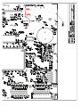
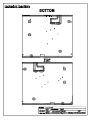
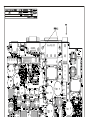
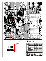
10 ASSEMBLY DRAWINGS................................................................................................................128
BTL-08 ECG Series
USER'S MANUAL
CONTENTS
1
GENERAL CHARACTERISTICS ........................................................................................................................4
2
INSTRUCTIONS FOR USE.................................................................................................................................5
2.1
Outward Appearance .....................................................................................................................................5
2.1.1
Top Panel of the Equipment .....................................................................................................................5
2.1.2
Keyboard ..................................................................................................................................................6
2.1.3
Rear Panel of the Equipment ...................................................................................................................6
2.2
Assembly and Putting into Operation .............................................................................................................7
2.3
Functions of the Keyboard Buttons ................................................................................................................7
2.3.1
auto ..........................................................................................................................................................7
2.3.2
man ..........................................................................................................................................................7
2.3.3
profile........................................................................................................................................................8
2.3.4
print ..........................................................................................................................................................8
2.3.5
stop...........................................................................................................................................................8
2.3.6
analyse .....................................................................................................................................................8
2.3.7
copy..........................................................................................................................................................8
2.3.8
1mV ..........................................................................................................................................................8
2.3.9
restart .......................................................................................................................................................8
2.3.10
number of leads........................................................................................................................................8
2.3.11
select leads ..............................................................................................................................................8
2.3.12
mm/s.........................................................................................................................................................9
2.3.13
mm/mV .....................................................................................................................................................9
2.3.14
filter- .........................................................................................................................................................9
2.3.15
drift ...........................................................................................................................................................9
2.3.16
monitor leads ............................................................................................................................................9
2.3.17
patient.......................................................................................................................................................9
2.3.18
menu ........................................................................................................................................................9
2.3.19
mode ......................................................................................................................................................10
2.3.20
print screen.............................................................................................................................................10
2.3.21
contrast...................................................................................................................................................10
2.3.22
esc..........................................................................................................................................................10
2.3.23
enter .......................................................................................................................................................10
2.3.24
up / down arrow......................................................................................................................................10
2.3.25
on/off ......................................................................................................................................................10
2.3.26
form feed (FF) ........................................................................................................................................10
2.3.27
restart - Restarting and Reset of the Device...........................................................................................10
2.4
Check of Loose Leads .................................................................................................................................11
2.5
Printer and Paper .........................................................................................................................................11
2.5.1
Paper Sensitivity.....................................................................................................................................11
2.5.2
Roll ECG Paper ......................................................................................................................................11
2.5.3
Fax Paper without Grid...........................................................................................................................12
2.5.4
Z-foldered Paper (perforated).................................................................................................................12
2.5.5
Storage Conditions for Thermo-Sensitive Paper ....................................................................................12
2.6
Accumulator .................................................................................................................................................13
2.7
Lithium Battery .............................................................................................................................................13
3
EXAMINATION..................................................................................................................................................14
3.1
"On Line" Mode ............................................................................................................................................14
3.2
Selection of Profile for ECG Recording ........................................................................................................14
3.3
Position of Electrodes ..................................................................................................................................14
3.3.1
Limb Electrodes......................................................................................................................................15
3.3.2
Chest Electrodes ....................................................................................................................................15
3.4
Examination Process ...................................................................................................................................15
3.4.1
Examination in the Automat Profile ........................................................................................................15
3.4.2
Examination in the Manual Profile ..........................................................................................................16
3.4.3
Examination in the Print Screen Profile ..................................................................................................16
3.4.4
Examination in the User Profiles ............................................................................................................16
3.4.5
Examination in the Long Profile..............................................................................................................16
3.5
Reliability of Measuring and Diagnostics......................................................................................................16
3.6
Use of Filters ................................................................................................................................................17
4
4.1
SETUP MODE ...................................................................................................................................................18
Main Menu ...................................................................................................................................................18
page
2
of
31
BTL-08 ECG Series
4.1.1
4.1.2
4.1.2.1
4.1.2.2
4.1.2.3
4.1.2.4
4.1.2.5
4.1.2.6
4.1.2.7
4.1.2.8
4.1.2.9
4.1.2.9.1
4.1.2.9.2
4.1.2.10
4.1.2.10.1
4.1.2.10.2
4.1.2.10.3
4.1.2.10.4
4.1.2.10.5
4.1.2.10.6
4.1.2.10.7
4.1.2.10.8
4.1.2.10.9
4.1.2.10.10
4.1.2.10.11
4.1.2.10.12
4.1.2.10.13
4.1.2.10.14
4.1.2.10.15
4.1.2.10.16
4.1.2.10.17
4.1.2.10.18
4.1.2.10.19
4.1.2.10.20
4.1.3
4.1.3.1
4.1.3.2
4.1.4
4.1.5
4.1.6
USER'S MANUAL
Record Database ...................................................................................................................................18
Unit Setup...............................................................................................................................................18
Starting Profile ..................................................................................................................................18
Max. Heart Rate................................................................................................................................19
QRS Acoustic Signal ........................................................................................................................19
Rhythm Lead ....................................................................................................................................19
Line Width.........................................................................................................................................19
Patient Card Setup ...........................................................................................................................19
Optional Patient Data........................................................................................................................19
Setting of Paper and Print.................................................................................................................19
Export Setup .....................................................................................................................................19
Transfer: Serial Cable->BTL08 ...................................................................................................19
Transfer: Modem->BTL08 ...........................................................................................................19
User Setup........................................................................................................................................20
Date / Time..................................................................................................................................20
Display Contrast..........................................................................................................................20
Select Language .........................................................................................................................20
Touch Panel Calibration ..............................................................................................................20
Repair of Files .............................................................................................................................20
File System Formatting ...............................................................................................................20
Default Setting - No User Data Loss ...........................................................................................20
Sleep Mode Interval ....................................................................................................................20
Battery Status Indication .............................................................................................................20
Demo ..........................................................................................................................................21
More… ........................................................................................................................................21
Unit Information...........................................................................................................................21
Information about Filesystem ......................................................................................................21
Setting of Filter 50 Hz / 60 Hz .....................................................................................................21
Setting of HW Key.......................................................................................................................21
Password Setting ........................................................................................................................21
Unlock Code................................................................................................................................21
Colour Schemes and Colours of Leads.......................................................................................21
Fast Data Processing ..................................................................................................................21
Automat Profile Print Speed ........................................................................................................21
Profile Setup...........................................................................................................................................22
Setting Auto, Man, Print Screen Profile Parameters .........................................................................22
Setting Parameters of Long Type Profiles ........................................................................................22
Select Patient .........................................................................................................................................22
Displayed Leads .....................................................................................................................................23
Select Physician .....................................................................................................................................23
5
5.1
5.2
ACCESSORIES AND UPGRADE .....................................................................................................................24
Accessories..................................................................................................................................................24
Upgrade .......................................................................................................................................................24
6
6.1
6.2
6.3
EQUIPMENT MAINTENANCE AND SAFETY ..................................................................................................25
Safety...........................................................................................................................................................26
Useful addresses .........................................................................................................................................27
Warranty ......................................................................................................................................................27
7
TECHNICAL PARAMETERS ............................................................................................................................28
page
3
of
31
BTL-08 ECG Series
1
GENERAL
USER'S MANUAL
CHARACTERISTICS
BTL-08Lx ECG Series devices are up-to-date ECG systems for monitoring and recording of resting
electrocardiogram. They provide detailed analysis*, diagnostics* and printing of ECG records. The outstanding
features including a wide variety of functions and easy operation make the unit an excellent cardiology tool.
BTL-08Lx ECG Series devices are equipped with accumulator batteries that make them fully portable equipment the
use of which is not limited to the physician’s office.
The assortment of types of the BTL-08Lx ECG Series devices include two devices equipped with the graphic display
and the 210-mm-wide printer which enables printing of all twelve leads at a time. The devices enable printing also on
the ordinary thermo-sensitive "fax" paper which significantly reduces the operational costs. The smaller b/w as well as
the larger colour display excel at the quality of displaying and are equipped with touch-panel which enables control
directly on the screen. You can select a device that will meet your requirements as perfectly as possible.
BTL-08Lx ECG Series devices stand out with easy and intuitive operation that can be quickly mastered by anyone.
ECG recording can start immediately after switch-on of the equipment.
Both types of the BTL-08Lx ECG Series devices have a patient database and enable to record and store in the
memory many 10-second and longer records from all leads and/or several-minutes-long records from two selected
leads – "LONG" type records. The equipment can be also used for ergometric examinations (in connection with the
BTL-08 Win Ergo software.
BTL-08Lx ECG Series devices can be also connected to the ergometry equipment which is controlled by the
computer with the BTL-08 Win Ergo program.
For the latest information about BTL products and contact to BTL companies please visit our website:
http://www.btlnet.com.
* only if the equipment is upgraded by the Diagnostics software module
page
4
of
31
BTL-08 ECG Series
2
2.1
USER'S MANUAL
INSTRUCTIONS
FOR
USE
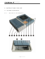
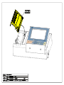
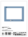
OUTWARD APPEARANCE
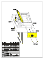
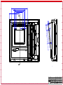
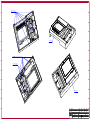
2.1.1
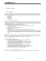
Top Panel of the Equipment
page
5
of
31
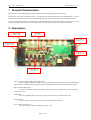
BTL-08 ECG Series
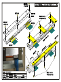
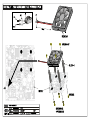
1.
2.
3.
4.
5.
6.
7.
8.
9.
10.
11.
12.
13.
2.1.2
USER'S MANUAL
printer cover
lever for opening the printer
touch screen
indication of ON status (power)
indication of charging of accumulators (charge)
indication of run-down accumulators (low batt)
indication of printer error (printer)
connector for the patient cable
keyboard for setting of print and record options
keyboard for setting of display view
holder for the fax paper
prop for the Z-foldered paper
tearing edge for the fax paper
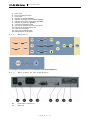
Keyboard
For description of individual buttons see Functions of the Keyboard Buttons.
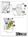
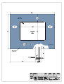
2.1.3
20.
21.
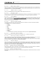
Rear Panel of the Equipment
power switch – positions 0 / I
mains fuse
page
6
of
31
BTL-08 ECG Series
22.
23.
24.
25.
26.
27.
2.2
USER'S MANUAL
mains cable connector
communication connector for connection to PC via the RS232 line
connector for connection to PC via USB
anti-interference clamp (on the bottom cover of the equipment)
type label
manufacture and warning label (on the bottom cover of the equipment)
ASSEMBLY AND PUTTING INTO OPERATION
Unpack the equipment and place it on a stable horizontal surface proportioned for the equipment's weight, out of
reach of sunlight. During the operation the equipment gets warm, therefore it must not be located close to heatproducing devices. Cooling of the equipment is provided by forced air circulation. Cooling vents are located at the
bottom of the equipment and around the display and must not be covered. Do not put the equipment on a soft surface
so as not to obstruct airflow to the bottom cooling vents. Do not put any heat-producing devices on the equipment,
neither objects containing water or other liquid. Do not place the equipment close to devices producing strong
electromagnetic, electric or magnetic field (diathermy, X-rays, etc.), otherwise the equipment could be undesirably
influenced. The ECG paper is heat-sensitive and therefore should be also located out of reach of heat emitters,
including sunlight - see Storage Conditions for Thermo-Sensitive Paper. In case of any questions please contact
the authorized BTL service department.
We recommend keeping the packing of the equipment for further possible transport.
Plug the device directly in the mains socket; do not use any multi-connection extension cable or adapter.
Switching the device on:
Plug the mains cable in the mains socket, switch the O/ I rocker switch (20) on the rear panel to the I position and
press the on/off switch on the keyboard. The ON status is indicated by the pilot light (4).
The mains switch (20) should be permanently in the I position so that recharging of the accumulators is ensured.
Recharging of accumulator:
The device contains an internal accumulator, which is sold in half-charged status. That is why we recommend
formatting of the accumulator after purchase of the device: connect the device to the mains with the mains rocker
switch (20) in position 1 for at least 48 hours without interruption. The device will be recharged and the accumulator
will be properly formatted. The properly formatted accumulator enables longer operation of the device without
recharging. For details see 2.6 Accumulator.
2.3
FUNCTIONS OF THE KEYBOARD BUTTONS
2.3.1
auto
Pressing of the print button in this profile starts recording of ECG signal from 12 leads and (for the types which are
equipped with the DIAGNOSTICS software module) its printing with analysis and verbal interpretation. Print reports
depend on the type and settings – for selection use buttons number of leads and select leads. At the same time, the
internal memory of the equipment stores 10 or more seconds of the signal (according to the settings) which can be
later printed, analyzed and saved to the patient data – buttons copy, analyse, patient, menu. The "auto" profile also
enables setting of retrospective printing (the minus time of start of printing), i.e. it is possible to print and save an event
which has already passed, up to 10 seconds back in time). To interrupt printing press the stop button. This mode is
indicated by the word "automat" in the status bar on the display.
The "auto" mode can be also selected directly on the touch screen. After touching the display at any point there
appear the top and bottom toolbars. After pressing the profile button there appears a menu containing all profiles
available in the device.
2.3.2
man
Manual recording of ECG signal from 12 leads. Number of printed leads depends on the settings - for selection use
buttons number of leads and select leads. This mode serves only for direct recording of the ECG signal, the signal
is not recorded in the memory. The print parameters can be selected even during printing. To start printing press the
print button, to stop printing press stop. This mode is indicated by the word "manual" in the status bar on the display.
page
7
of
31
BTL-08 ECG Series
USER'S MANUAL
The "manual" mode can be also selected directly on the touch screen. After touching the display at any point there
appear the top and bottom toolbars. After pressing the profile button there appears a menu containing all profiles
available in the device.
2.3.3
profile
Selection of one of possible user profiles (all profiles except auto, man and print screen - see above) which can be
edited in profile setup. The highlighting shifts cyclically on the available profiles. Recording is run according to
parameters which are preset in the equipment's memory. At the same time, the internal memory of the equipment
stores 10 or more seconds of the signal (according to the settings) which can be later printed, analyzed and saved to
the patient data – buttons copy, analyse, patient, menu (only for profiles derived from the automat type). To interrupt
printing press the stop button. The current mode is indicated in the bottom status bar on the display.
The profile can be also selected directly on the touch screen. After touching the display at any point there appear the
top and bottom toolbars. After pressing the profile button there appears a menu containing all profiles available in the
device.
2.3.4
print
Press this button to start printing of the record and possibly saving in the memory in the set profile.
2.3.5
stop
Press this button to interrupt the running print. If the device is busy, e.g. by analysis of the signal, the response for
pressing the stop button may be delayed. In such case wait until the device stops the running operation and then
press the button again.
2.3.6
analyse
Button for printing of verbal interpretation and the table with the results of analysis of the last record taken in the
automat or a derived mode. It is active only if the DIAGNOSTICS module is implemented.
2.3.7
copy
Button for reprinting of the last record taken in the automat or a derived mode. Printing is performed with the current
values of filters, sensitivity and speed, so, if the values have changed since the last recording in the automat mode,
the result of the print may differ from the original. If you need an absolutely identical copy, set the speed, sensitivity
and filters the same as in the original and only then press copy.
2.3.8
1mV
Button for printing of the calibration signal of the amplitude 1 mV. The mark is printed only when printing in the
manual mode.
2.3.9
restart
Button for restarting of ECG inputs and ECG internal amplifiers. Use this button if you are not sure about the quality of
the measured ECG record or if the ECG-curves are out of the display.
2.3.10
number of leads
Button for selection of the number of leads to be printed. To select the required combination press this button
repeatedly. The current combination is displayed in the top status bar on the display. The resulting setting depends on
the currently selected profile, manual or automat.
The number of leads to be printed can be also selected directly on the touch screen. After touching the display at any
point there appear the top and bottom toolbars. After pressing the print button there appears a screen containing all
possible numbers of leads to be printed.
2.3.11
select leads
Button for selection of groups of leads to be printed. The groups of leads cyclically shift when pressing the button. The
selected leads are displayed in the top status bar on the display. The function is active only in the manual mode and
only if less than 12 leads at a time are printed.
page
8
of
31
BTL-08 ECG Series
2.3.12
USER'S MANUAL
mm/s
Button for setting of the paper feed speed. The particular speed values cyclically shift when pressing the button. The
current paper speed is displayed in the top status bar on the display.
The paper speed can be also selected directly on the touch screen. After touching the display at any point there
appear the top and bottom toolbars. After pressing the speed button there appears a screen containing all possible
values of the paper speed.
2.3.13
mm/mV
Button for setting of the sensitivity of print. The particular sensitivity values cyclically shift when pressing the button.
The current sensitivity value is displayed in the top status bar on the display. Sensitivity can be also changed during
printing in the manual mode.
Sensitivity can be also selected directly on the touch screen. After touching the display at any point there appear the
top and bottom toolbars. After pressing the sensitivity touch button there appears a screen containing all possible
values of record sensitivity.
2.3.14
filter-
Button for setting of mains noise filter, muscular filters and artifact filter. The particular filters or their combinations
cyclically shift when pressing the button. The current filter or combination of filters is displayed in the top status bar on
the display. It is possible to select the adaptive auto filter which on the basis of the signal analysis automatically
activates the needed filter so that the quality of the resulting signal is maximum. The adaptive auto filter cannot be
combined with other filters.
Filters and their combinations can be also selected directly on the touch screen. After touching the display at any point
there appear the top and bottom toolbars. After pressing the filters button there appears a screen containing all
available filters. Here it is possible to activate any filter or combination.
2.3.15
drift
Button for cyclical switching among the base-line filters (Anti Drift System). The current filter or combination of filters is
displayed in the top status bar on the display. It is possible to select the adaptive auto filter which on the basis of the
signal analysis automatically activates the needed filter so that the quality of the resulting signal is maximum. The
adaptive auto filter cannot be combined with other filters.
Filters and their combinations can be also selected directly on the touch screen. After touching the display at any point
there appear the top and bottom toolbars. After pressing the filters button there appears a screen containing all
available filters. Here it is possible to activate any filter or combination.
2.3.16
monitor leads
Button for cyclical switching among the leads displayed on the screen. If the screen displays less than 12 leads at a
time, this button enables to switch cyclically to other leads which are not currently displayed. The displaying and
number of leads depends on the current display setting (mode button).
The leads for displaying can be also switched on the touch screen. After touching the display at any point there
appear the top and bottom toolbars. The monitor leads button on the screen has the same function as the analogous
button on the keyboard.
2.3.17
patient
Button for opening of the dialogue window for entering data of a new patient. To save data press OK. These data are
printed in the record and stored in the memory together with the record and can be loaded from the database (see
Record Database) in the menu, viewed and/or printed on the ECG paper. The types of data to be entered and stored
can be selected in the unit settings (see Patient Card Setup).
2.3.18
menu
Button for activation of the menu containing the unit setup, patient data management, etc.
The menu can be also entered directly from the touch screen. After touching the display at any point there appear the
top and bottom toolbars. After pressing the menu button (in the lower right corner) there appears a menu as after
pressing the keyboard button.
page
9
of
31
BTL-08 ECG Series
2.3.19
USER'S MANUAL
mode
Button for selection of the arrangement of displaying of leads on the display, from 3 leads on the display at a time up
to all 12 lead in more columns. All possible variants of displaying rotate on the screen when pressing the button.
The appearance on the display can be also changed in details on the touch screen. After touching the display at any
point there appear the top and bottom toolbars. After pressing the menu button on the keyboard or on the display the
device menu appears which contains the displayed leads button. After pressing the button there appears a screen
containing all available display combinations including the possibility of assigning a certain lead to a certain window on
the display.
2.3.20
print screen
Button for instant printing and saving of the screen status using the special print screen profile. This profile serves for
capturing of sudden artifacts which the operator spots on the display, therefore recording and printing starts
immediately after pressing this button and it is not necessary to start recording by the print button. This profile also
enables to set retrospective printing (the minus time of the start of printing), i.e. it is possible to print and save an
event which has already passed, up to 10 seconds back in time. The profile is configured similarly to the "auto" profile.
2.3.21
contrast
Button for prompt setting of the display contrast. The contrast can be also changed in the equipment settings menu.
Note:
At the colour display, the change of contrast may lead to change of the colour representation of the current colour
scheme.
2.3.22
esc
Button for rejection of a selection and/or return to a higher dialogue window in the menu without saving the entered
values.
The touch button on the screen, if displayed, has the same function as the keyboard button.
2.3.23
enter
Button for confirmation of a selection and saving of the value and/or for entering the lower window in the menu.
The touch button on the screen, if displayed, has the same function as the keyboard button.
2.3.24
up / down arrow
Buttons for movement in the menu and/or for change of values.
The touch buttons on the screen, if displayed, have the same function as the keyboard buttons.
2.3.25
on/off
Button for switching the device on / off. At switching off, the device checks the status of the accumulators and if it finds
them low, it switches to the charging mode; in the charging mode the display is dark and the power and charge
indicators are shining. After recharging of the accumulator the device automatically switches off completely. The
charging mode is activated only if the device is plugged in the mains and the mains rocker switch (20) on the rear
panel is in the I position. If the device is not connected or the switch (20) is in the 0 position, the device switches off.
Note!
Checking of the accumulator status takes some time, therefore the device may respond with a delay after switching off
and then on again.
All saved data remain stored even if power supply is off.
2.3.26
form feed (FF)
This button is available only on the touch screen. After touching the display at any point there appear the top and
bottom toolbars. The FF ("form feed") button is in the bottom left corner. After pressing this button the paper slightly
ejects from the printer, either to the next page (Z-foldered paper) or by approx. 3cm (fax paper). The button may be
pressed repeatedly. For details on how to work with paper see Printer and Paper.
2.3.27
restart - Restarting and Reset of the Device
If for some reason (electromagnetic interference, etc.) the device stops responding to the user's commands
(keyboard, touch panel) and the message "please wait..." with small moving squares are not displayed, the device can
page
10
of
31
BTL-08 ECG Series
USER'S MANUAL
be put into the initial state by simultaneous pressing of the esc and restart buttons. After this action the device
immediately restarts. After the restart it is possible to continue the work with the device.
Note:
If the device is in the above-described state ("no response"), the on/off button is also disabled. The only help is to
reset the device, as described above.
2.4
CHECK OF LOOSE LEADS
If an electrode is wrongly attached to the patient, has bad contact or is not connected, ECG warns of this fact by
symbolic texts in the bottom status bar on the display (texts RLFN, V1, V2, V3, V4, V5, V6). In such case it is
recommended to check attachment of the electrodes, press the restart button and record the ECG signal only after
the equipment stops reporting error.
If you continue recording when the equipment reports a problem on a lead, there may occur considerable distortion of
the signal.
Note:
When using the automat profile, the device checks the quality of signal (connection of electrode) before recording, and
starts recording only when all electrodes are properly connected. This function can be enabled/disabled in the profile
configuration. The individual stages of recording are clearly indicated on the display.
2.5
PRINTER AND PAPER
The used printer prints on thermo-sensitive paper. Quality of the paper may considerably affect quality of the printed
ECG-curves. For high-quality printing it is recommended to use only the BTL-recommended paper.
The yellow pilot light (7) indicates printer error status. Possible causes:
•
printer is out of paper
•
improperly closed printer cover or wrong type of paper or wrongly set type of paper.
At the same time there appears an error message with additional information on the display.
2.5.1
Paper Sensitivity
Each type of paper has slightly different sensitivity to thermal impulses produced by the printer. The resulting printout
can be too bright and illegible or, on the other hand, too dark or even overburned (overburned print has a white centre
in the printed line).
For the above reasons the device is designed so that it adapts to various types of paper. For setting the paper
sensitivity use the paper sensitivity item in menu – unit setup – setting of paper and print. The more sensitive
paper is set, the brighter is the resulting printout. There are 5 levels of sensitivity setting available. It is recommended
to test the setting on several printouts after any change of the paper type.
2.5.2
Roll ECG Paper
The device can print on the thermo-sensitive fax (=roll) paper with preprinted grid, nominal width 210 mm (for more
detailed specification see Chapter Technical Parameters). For high-quality print we recommend exclusive use of
paper supplied by the BTL companies. For the fax paper, the paper type must be correctly selected in menu – unit
setup - setting of paper and print - type for fax. When using the paper with the preprinted grid it is necessary to
disable the print grid item on the same screen. If the printer contains another type of paper than set in the unit setup,
the device reports an error after a short while of printing.
Inserting paper: Press button (2) to open the printer cover (1). Tilt the fax paper holder (11) towards the printer. Insert
the paper roll, the thermo-sensitive layer (grid) facing the printer head (display) so that the paper overlaps the tearing
edge (13). Click the printer cover shut. The pilot light (7) indicating that the printer is out of paper stops shining. The
printer is ready. To check if the paper is inserted and set correctly check menu – unit setup - setting of paper and
print after pressing the insert paper touch button.
The button for inserting paper or feed to the next page (FF – form feed) is available also in the lower left corner of the
on-line screen after touching the screen at any point. By this button you can eject the paper slightly from the printer at
any time.
page
11
of
31
BTL-08 ECG Series
USER'S MANUAL
Tearing of paper: It is recommended to tear the fax paper by pulling it from the bottom margin over the tearing edge
13 towards the display.
ATTENTION
It is essential to insert paper carefully and absolutely parallel to the tearing edge (the grid on the paper must
be parallel to the tearing edge), otherwise it will later bend to a side and possibly crumple or tear.
2.5.3
Fax Paper without Grid
The device can also print on a standard thermo-sensitive white fax paper without the preprinted grid. In such case it is
necessary to enable the print grid item in menu – unit setup - setting of paper and print. Other settings and
handling are the same as for the paper with the preprinted grid.
ATTENTION
It is essential to insert paper carefully and absolutely parallel to the tearing edge, otherwise it will later bend
to a side and possibly crumple or tear.
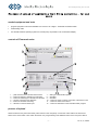
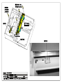
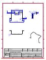
2.5.4
Z-foldered Paper (perforated)
It is also possible to use the thermo-sensitive Z-foldered paper with preprinted grid, nominal width 210 mm (for more
detailed specification see Chapter Technical Parameters). For high-quality print we recommend exclusive use of
paper supplied by the BTL companies. For the Z-foldered paper, the paper type must be correctly selected in menu –
unit setup - setting of paper and print - type perforated (Z-foldered). At the first use of a new type of Z-foldered
paper it is necessary to measure some of its dimensions and enter the measured values in the device. The
dimensions are: page width of the used paper (C), mark width (B) and distance between the mark and perforation (A).
The measured dimensions are indicated in the picture on the screen. The arrow shows in which direction the paper
gets out of the device. If the wrong values are set, the device will not eject the paper properly on the perforation which
will prevent proper tearing of paper. If paper with the preprinted grid is used, disable the print grid item. If there is
inserted another type of paper than set in the unit setup, the device reports an error at the attempt for printing. Never
insert more paper sheets in the paper stack than stated in Chapter Technical Parameters.
Inserting paper: Press button (2) to open the printer cover (1). Tilt the fax paper holder (11) away from the printer
(display). Insert the Z-foldered paper bundle in the paper stack, the thermo-sensitive layer (grid) facing the printer
head (display) so that the paper overlaps the tearing edge (13). Click the printer cover shut. The pilot light (7)
indicating that the printer is out of paper stops shining. The printer is ready. To check if the paper is inserted and set
correctly check menu – unit setup - setting of paper and print after pressing the insert paper touch button (if all
dimensions of the paper are set correctly, the paper ejects from the device up to the next perforation. We recommend
using this button after each insertion (replacement) of Z-foldered paper.
The button for inserting paper or feed to the next page (FF – form feed) is available also in the lower left corner of the
on-line screen after touching the screen at any point. By this button you can eject the paper slightly from the printer at
any time.
Tearing of paper: We recommend not to tear the Z-foldered paper over the tearing edge 13 (which is designed
particularly for the fax paper) but over the edge of the printer cover, away from the display. Thus the paper will tear
exactly along the perforation and its margin will not be damaged by the tearing edge.
Note:
For easier taking the Z-foldered paper out serves the prop (12) which enables to lift the bundle up and then take it in
hand and pull out of the paper stack.
ATTENTION
It is essential to insert paper carefully and absolutely parallel to the tearing edge (the grid on the paper must
be parallel to the tearing edge), otherwise it will later bend to a side and possibly crumple or tear.
THE Z-FOLDERED PAPER IS EXTREMELY SENSITIVE TO PROPER INSERTION. IF IT IS INSERTED
IMPROPERLY IT CRUMPLES AND TEARS DURING PRINTING.
2.5.5
Storage Conditions for Thermo-Sensitive Paper
The printer is designed for thermo-sensitive paper. To achieve as long as possible time stability of the printout, it is
essential to keep the following terms of storage of new as well as of the printed paper:
•
storage temperature
25 °C and lower
•
relative humidity
65% and lower
•
do not expose paper to the sunlight
•
do not expose paper to long-lasting radiation of fluorescent sources (tubes, etc.)
page
12
of
31
BTL-08 ECG Series
•
•
2.6
USER'S MANUAL
prevent contact of paper with glue based on alcohol, ester, ketone, etc. Use only dispersive glue based on
starch, PVA or CMC.
prevent any direct contact of the paper with PVC packages. These packages contain substances based on
ester which would spoil the thermo-sensitive layer and cause vanishing of the record.
ACCUMULATOR
The type of the accumulator is stated in Chapter Technical Parameters. Its replacement is provided by the
authorized BTL service department.
During operation the accumulator is continuously being recharged from the mains. Its recharging and keeping charged
is running even if the equipment is switched off and connected to mains and the mains switch (20) on the rear panel is
in position I. At switching off, the device checks the status of the accumulators and if it finds them low, it switches to
the charging mode; in the charging mode the display is dark and the power and charge pilot lights are shining. After
recharging of the accumulator the device automatically switches off completely. Note that the charging process runs
only if the device is plugged in the mains and the rocker switch (20) on the rear panel is in the I position.
Checking of the accumulator status may take some time, therefore the device may respond with a delay after
switching off and then on again.
For full charging of the accumulator let it recharge for approximately 6 hours – preferably overnight.
A low accumulator is signalled in two levels of signalling.
•
the accumulator is low, but it is still possible to print for a short time – the low batt indicator (6) is blinking
•
the accumulator is dead, the device cannot print – the low batt indicator (6) is shining permanently and at the
same time there is a warning acoustic signal (short intermittent beeping approx. once every 20 seconds). The
acoustic signalling can be disabled, see Chapter Battery Status Indication.
During charging of the accumulator the charge indicator (5) is shining.
If the "low battery" status is indicated, it is likely that the equipment will not be able to print the entire ECG record.
During recording and printing the process may be interrupted. However, the data are still saved in the memory and
can be printed after recharging of the accumulator.
To ensure a long lifetime of the accumulator we recommend keeping it permanently charged. When it is possible,
connect the ECG to the mains and put the mains switch (20) to the I position. The pilot light (5) will start shining (after
recharging it will go out) and the accumulator will be automatically kept in the charged status.
If the device is left unplugged from the mains for a longer time (even in the OFF status), the accumulators gradually
spontaneously discharge. This effect is characteristic of the accumulators and cannot be removed; therefore, if the
device has been off and unplugged for a longer time than approximately 2-3 months, we recommend recharging it,
preferably for 48 hours without interruption.
For the same reason we recommend charging the device continuously for at least 48 hours immediately after
purchase, regardless of the accumulator status indication (you can work with the device normally, only do not unplug it
from the adapter, the accumulator recharges even during standard operation of the device). Thus the accumulator
gets so –called formatted and will keep working longer without recharging.
2.7
LITHIUM BATTERY
The device contains a lithium battery for backup of date and time. The type of the battery is written in Chapter
Technical Parameters. Its replacement is provided by the authorized BTL service department.
page
13
of
31
BTL-08 ECG Series
3
3.1
USER'S MANUAL
EXAMINATION
"ON LINE" MODE
This mode is automatically started after switch-on of the equipment. The display in this mode displays the recorded
ECG signal and the following information:
•
the selected print profile (auto, manual, long…)
•
heart rate (HR)
•
paper speed
•
set sensitivity
•
set filters
•
loose leads, if any
•
names of the displayed leads
•
number and names of leads to be printed
•
ECG-curve
•
during saving of a 10-sec-long to 80-sec-long record in the equipment's memory there is displayed
description and indicator of the progress
•
if the device is busy (e.g. by analysis or interpretation), the display show the message "please wait…".
After touching the screen in the on-line mode there appear the top and bottom toolbars with buttons serving for setting
of parameters, similarly as the keyboard. After approximately 2 seconds without a touch, the toolbars automatically
hide.
After switch-on the equipment permanently monitors the input ECG signal and always remembers the last 10 seconds
of the signal. This signal can be retrospectively stored and printed in a suitable profile and settings (profile auto or
print screen, item start time lower than 0 (0 = start at the moment of pressing the button, -10 = start of printing of the
signal 10 seconds before pressing the button)).
3.2
SELECTION OF PROFILE FOR ECG RECORDING
Profiles are pre-set recording and printing parameters that serve for quick setting of the equipment for print.
Parameters of the profiles are preset by the manufacturer and can be changed in the equipment's menu. Besides
basic profiles automat (auto button), manual (man button) and print screen (print screen button) it is possible to
set many user profiles (when pressing the profile button, the available profiles cyclically shift).
The set profile parameters can be changed by pressing of the respective button at any time before and/or during
recording.
To start recording of the signal press the print button. Termination of recording is either automatic after the time set in
the profile elapses, or manual by pressing the stop button. Depending on the set profile, the device may record data
or analyse the signal for some more time. If the device is performing a background job, a small blinking circle appears
in the upper right corner of the display, or a circle with the text "wait please". The analysis and storage of the signal
may be very time-consuming operations.
3.3
POSITION OF ELECTRODES
Quality of the ECG record is particularly dependent on the contact between the electrode and the patient's skin. To
keep the contact as good as possible please observe the following principles:
•
the skin should be warm and the patient relaxed
•
before fastening the electrode cleanse the skin with alcohol
•
apply sufficient layer of gel on the electrode
It is recommended to fasten the electrodes in the following order:
•
first fasten the N electrode to the right leg
•
then fasten the other limb electrodes R, L, F
•
finally fasten the chest electrodes in the following order: V4 – V2 – V1 – V3 – V6 – V5
The following two parts of this document contain the detailed description of the electrodes position.
page
14
of
31
BTL-08 ECG Series
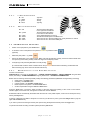
3.3.1
USER'S MANUAL
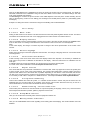
Limb Electrodes
R – red
L – yellow
F – green
N – black
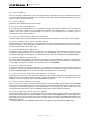
3.3.2
Chest Electrodes
V1 – red
V2 – yellow
V3 – green
V4 – brown
V5 – black
V6 – violet
3.4
- right arm
- left arm
- left leg
- right leg
- the fourth intercostal space
to the right from the sternum
- the fourth intercostal space
to the left from the sternum
- in the middle between V2 and V4
- the fifth intercostal space in the MDCL line
- at the level of V4 in the front axillary line, evenly between V4 and V6
- at the level of V4 in the central axillary line
EXAMINATION PROCESS
•
Switch on the equipment by the on/off button:
•
To enter the name of the patient to be printed in the record press the button:
(optional)
•
Select the print profile – e.g. auto:
•
Fasten the electrodes to the patient's body. Make sure that all leads are properly connected and that ECG does
not report any loose leads; possibly check if the signal on the display is clear.
•
If everything is OK press the print button to start printing:
(If in the automat mode the check of leads is ON in the profile, the device waits for fastening of electrodes and
starts recording only when contact of all electrodes is OK)
3.4.1
Examination in the Automat Profile
Process of examination:
SWITCH ON the unit using the on/off button – FASTEN THE ELECTRODES – SELECT PROFILE using the auto
button (Unit Setup) – START RECORDING using the print button – AUTOMATIC TERMINATION.
Before start of recording check and possibly modify the following parameters (cannot be changed during recording):
•
paper speed - the mm/s button
•
sensitivity - the mm/mV button
•
number of leads - the number of leads button
•
leads required to be printed - the select leads button
•
set the required filers using the filter and drift buttons.
Press the print button. The device starts recording of the ECG signal and printing of the curves on the thermosensitive paper; at the same time, the signal is stored in the records database.
Examination will be automatically terminated after the time set in the profile elapses; it also can be interrupted at any
time by the stop button.
If printing of diagnosis and table of analysis is not set but you still want to print it, press the analyse button (only the
types with DIAGNOSTICS).
If you want to print the record again set the print options using the keyboard and then press the copy button.
To perform automatic recording of another patient press the print button.
page
15
of
31
BTL-08 ECG Series
3.4.2
USER'S MANUAL
Examination in the Manual Profile
Process of examination:
SWITCH ON the unit – FASTEN THE ELECTRODES – SELECT PROFILE using the man button (Unit Setup) –
START RECORDING using the print button – TERMINATE or INTERRUPT recording using the stop button.
Before start of recording check and possibly modify the following parameters (it is also possible to change them during
recording):
•
paper speed - the mm/s button
•
sensitivity - the mm/mV button
•
number of leads - the number of leads button
•
leads required to be printed - the select leads button
•
set the required filers using the filter and drift buttons.
Press the print button. The device starts printing of the curves on the thermo-sensitive paper.
To terminate recording press the stop button.
To print record of another patient press the print button.
Note:
In the manual mode the data of the ECG signal are not stored in the records database.
3.4.3
Examination in the Print Screen Profile
Process of examination:
SWITCH ON the unit – FASTEN THE ELECTRODES – START RECORDING using the print screen button –
AUTOMATIC TERMINATION or INTERRUPTION by the stop button.
The process is very similar to that in the automat mode – see Chapter Examination in the Automat Profile.
3.4.4
Examination in the User Profiles
Process of examination:
SWITCH ON the unit – FASTEN THE ELECTRODES – SELECT PROFILE using the man button (Unit Setup) – START
RECORDING using the print button – AUTOMATIC TERMINATION or INTERRUPTION by the stop button.
Further process of examination is very similar to that in the automat resp. manual mode – see Chapter Examination
in the Automat Profile or Examination in the Manual Profile.
3.4.5
Examination in the Long Profile
Process of examination:
SWITCH ON the unit – FASTEN THE ELECTRODES – SELECT PROFILE OF THE long TYPE using the man button
(Unit Setup) – START RECORDING using the print button – AUTOMATIC TERMINATION or INTERRUPTION by
the stop button.
Further process of examination is very similar to that in the automat mode – see Chapter Examination in the
Automat Profile.
3.5
RELIABILITY OF MEASURING AND DIAGNOSTICS
Parameters that are analysed on the basis of an averaged heart cycle are considered correct if the relevant record is
not distorted too much by the mains noise, by artefacts of myopotentials, or by other noises. Another factor for
reliability is that the unit correctly recognises the key points of the P-QRS-T complex. The accuracy of parameters
may be also affected by inclusion of aberrant cycles to the averaged cycle in case that the unit incorrectly classifies
them as typical for the given record. The unit attempts to determine the parameters of every record automatically;
therefore it is necessary to ensure that at least three cycles typical for the record analysis are correctly averaged and
that the number of aberrant cycles does not exceed the number of non-aberrant ones.
page
16
of
31
BTL-08 ECG Series
3.6
USER'S MANUAL
USE OF FILTERS
Fully automatic adaptive filter (adaptive auto) – a filter which performs permanent analysis of the recorded signal
and on the basis of the acquired data filters the signal so as to achieve the optimum result. This filter comprises all
other filters, therefore it CANNOT be combined with other filters.
Adaptive filter of mains noise (50 Hz-60 Hz) – a filter designed for reduction of the noise that penetrates the record
from the mains, with the ability of adaptation to the changes in the frequency of the noise. Harmonic (sinus) waveform
with a period of approximately 1 mm at the record speed of 50 mm/sec is typical for this type of noise. The filter does
not affect any of the diagnostically important parameters of the record. "Adaptive" means that the filter can
automatically adapt to both mains frequencies 50Hz and 60Hz. For faster stabilization of the filter it is recommended
to set the correct value according to the current mains in menu-unit setup-user setup-more…-mains frequency.
Muscular filter 35 Hz – a filter with cut-off frequency 35 Hz designed for removing of muscular artefacts. This noise is
characterised by non-harmonic waveform with short random period. This filter removes the mains noise as well. In
certain cases this filter may affect some values of the amplitude of the QRS complex.
Muscular filter 25 Hz – a filter with cut-off frequency 25 Hz designed for removing of muscular artefacts. This noise is
characterised by non-harmonic waveform with short random period. This filter removes the mains noise as well. Use
of this filter is recommended in limited cases when muscular artefacts considerably distort the record. This filter may
affect some values of the amplitudes of the QRS complex.
Anti Drift System – base line: – filters for removing of the base-line drift. Use these filters in cases when the baseline drift in the recorded examination is significant. Follow this scheme: As the starting filter always use the filter with
the longest time constant – ADS 3.2 sec. If the base-line drift is significant and the ECG record escapes from the
record (or from the display), switch the ADS filter successively to the filters with faster reaction, i.e. with shorter time
constant. That is, from the original value ADS 3.2 sec towards the value of 0.1 sec. However, the value ‘heart rate x
time of reaction of the filter‘ should always be much more than 10, so that the record is not significantly influenced.
When using these filters with fast reaction (small number in the filter's name – 0.1 sec) it is necessary to keep in mind
that filtration may in some cases result in some distortion of the P-QRS-T intervals. This is especially true for the
diagnostically important S-T interval.
Filter ADS 3.2 sec is a standard filter for ECG recording and is recommended for use. Generally it is recommended to
try to get as-good-as-possible record and limit use of all filters to minimum.
All the stated filters can be mutually combined so that the filtration of the record is optimum.
page
17
of
31
BTL-08 ECG Series
4
4.1
SETUP
USER'S MANUAL
MODE
MAIN MENU
To enter this menu, press the button menu in the lead monitoring mode. The menu can be also entered using the
touch screen: After touching the display at any point there appear the top and bottom toolbars. After pressing the
menu button (in the lower right corner) there opens the main menu. Here you can select from the following options:
•
Record Database
•
Unit Setup
•
Profile Setup
•
Select Physician
•
Displayed Leads
4.1.1
Record Database
This menu enables to open, view and print the last taken records. The records are stored in the memory
automatically. If the memory is full, the next taken record overwrites the oldest stored record. The records which are
marked as archive (mark button, a + sign is displayed in front of the record) are not overwritten and remain in the
memory permanently (if you want to delete them, you have to do it manually).
With the selected record you can perform the following actions:
•
reprint the record with the setting which it was recorded with, or with any other setting
•
change the print profile
•
view the record on the display, including analysis
•
mark/unmark the record as archive
•
delete the record
•
display the record optionally sorted according to the attribute archive, date, name or ID
•
export the selected record, current record or all records to the PC or fax (to receive data from the unit the PC
must be equipped with the registered BTL-08 Win or BTL-08 Ergo software. The unit must be connected to
the PC or modem by a cable). Data are transferred via the selected transfer channel, see Chapter Export
Setup.
Note:
The records are stored in the memory in compressed format, so that there can be stored as many records as
possible. That is why at first entering the archive the device has to convert these records into readable format. This
operation may take several seconds, depending on the number of the stored records.
4.1.2
Unit Setup
This submenu includes the following options:
•
select profile which the device starts with after switch-on (starting profile)
•
set maximum heart rate alarm (max. heart rate)
•
switch on / off acoustic signalling of the QRS complex (QRS acoustic signal)
•
set the lead from which the device determines the heart rhythm (rhythm lead)
•
set the ECG-signal print line width (line width)
•
select information to be displayed in the patient card (patient card setup)
•
set optional patient data (optional patient data)
•
set the print parameters and the used paper type (setting of paper and print)
•
set the parameters of export of the stored records to PC (export setup)
•
enter another user setup menu of the device (user setup)
4.1.2.1
Starting Profile
Here you can select the profile that will be automatically set after switching the equipment on by the on/off button.
page
18
of
31
BTL-08 ECG Series
4.1.2.2
USER'S MANUAL
Max. Heart Rate
Here you can set the heart rate value which the equipment will consider the highest allowed. If the measured heart
rate is higher than this set value the equipment makes warning by high intermittent beeping. If this maximum heart
rate value is set to zero – 0 – the function is disabled.
4.1.2.3
QRS Acoustic Signal
Here you can enable/disable the acoustic signalling of QRS complex of the ECG-curve.
4.1.2.4
Rhythm Lead
Here you can set from which lead the device will determine the heart rate. In most cases it is not necessary to change
the default settings, in special cases the lead can be changed (e.g. in some types of ergometric examination).
4.1.2.5
Line Width
Here you can set width of the ECG-curve printed on the paper. The setting shall be refined according to the used
paper. This setting influences only the printing of the ECG-curve itself, not the printing of other information (texts,
grids, pictures). Using this setting, together with setting of the suitable paper sensitivity (see above) it is possible to
achieve the optimum appearance of the print.
4.1.2.6
Patient Card Setup
The enabled items appear during entering the patient data and can be filled in. The data are stored with the patient.
In the patient card you can enable the following items:
•
name
•
surname
•
third name
•
ID
•
age
•
sex
•
weight
•
blood pressure
•
height
•
pacemaker
•
2 user-defined items, the meaning and description of which can be set in Optional Patient Data.
4.1.2.7
Optional Patient Data
Here you can define names of two optional items of the patient card – e.g. diagnosis, general state...
4.1.2.8
Setting of Paper and Print
Here it is possible to set many important parameters of printing: if the print paper is perforated or for fax, if the grid
shall be printed, paper sensitivity, and it is also possible to get the paper inserted after its replacement.
Setting of paper sensitivity is important for optimum printing, and besides the line width it influences the print quality
the most. For details on paper settings see Chapter Printer and Paper.
4.1.2.9
Export Setup
Here you can select which of the available transfer channels will be used for export of data to the PC or fax. At the
same time it is possible to configure the channel. In most cases the default setting is sufficient. Data are transferred
from the unit to the BTL-08 Win or BTL-08 Ergo program. The selected communication channel will be used in the
export option in the Record database, see Record Database.
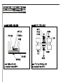
4.1.2.9.1
Transfer: Serial Cable->BTL08
When exporting data to the PC via the cable, no special setting is necessary. The connection speed is 115200baud.
The BTL08Win/Ergo program must be running on the PC and the receiving form must be open.
4.1.2.9.2
Transfer: Modem->BTL08
When exporting via the phone line, a modem or a mobile phone equipped with a hardware modem must be connected
to the ECG.
page
19
of
31
BTL-08 ECG Series
USER'S MANUAL
Write in the init string box the initialization text string for putting the modem into the required mode. For details on
individual commands in the initialization string see the User's Guide of the modem. The default settings work with
most of the standardly sold modems.
The dial string box contains the phone number of the called telephone. Enter the phone number including the test
string at the beginning: ATDT for tone dialling (new exchanges and mobile phones) ATDP for pulse dialling (older
exchanges).
Example: for calling the number 2 333 555 84 using the tone dialling enter ATDT233355584.
4.1.2.10
User Setup
4.1.2.10.1 Date / Time
Setting of date and time in the device. This date and time are stored and printed together with the records. The device
remembers the set date and time even if it is unplugged from the mains and the accumulators are low.
4.1.2.10.2 Display Contrast
Here it is possible to set the required display contrast. The function is the same as after pressing the contrast button
in the on-line screen. For setting of contrast use the arrow buttons on the touch screen or on the keyboard.
Note:
At the colour display, the change of contrast may lead to change of the colour representation of the current colour
scheme.
4.1.2.10.3 Select Language
Setting of the language in which the equipment communicates. The change of language does not occur before restart
of the equipment.
4.1.2.10.4
Touch Panel Calibration
If after touching of the touch screen there react other display buttons than required, it is necessary to calibrate the
touch panel. The process of calibration is described on the display - follow the instructions. For calibration use the
touch-pen.
If calibration does not proceed successfully you can interrupt it at any time by pressing esc.
For check of the result of calibration use the touch panel function test function.
4.1.2.10.5
Repair of Files
If the stored data are corrupt because of interference or a device fault, there may appear errors in the file system (loss
of some records, loss of some of the stored patients). This function starts diagnostics of the file system and tries to
repair the fault without loss of the stored data, if possible. Depending on the amount of the stored data, this function
can take a very long time (hours), therefore we recommend running this function e.g. overnight. If this function is run,
it is necessary to wait until it is complete or to reset the device - see Chapter Functions of the Keyboard Buttons.
4.1.2.10.6
File System Formatting
This function initializes the entire file system, i.e. it deletes all data stored in device and puts the device into the
initialized state (i.e. the same state as at purchase of the device). This function should be used only in case of a
serious breakdown or if the user wants to initialize the device completely.
4.1.2.10.7
Default Setting - No User Data Loss
This function puts the device into the same state as at purchase (setting of language, colours, etc.) and at the same
time it keeps all stored data of profiles, patients, physicians and records.
4.1.2.10.8 Sleep Mode Interval
Here you can set the time of inactivity after which the equipment switches off.
4.1.2.10.9
Battery Status Indication
Here you can enable/disable the acoustic signalling of low battery (short fast beeping). The visual indication cannot be
disabled.
page
20
of
31
BTL-08 ECG Series
USER'S MANUAL
4.1.2.10.10 Demo
Here you can switch on/off the demo mode of the signal recording. If the Demo mode is on, the device behaves as if it
were connected to the patient, although it is not. The Demo mode is indicated by bold letterings DEMO on the on-line
screen as well as on the printed record.
4.1.2.10.11 More…
This button opens additional items of the user setup.
4.1.2.10.12 Unit Information
In this item all key information about the unit configuration is listed: serial number, firmware version, until when the
function of the device is limited, version of diagnostics, temperature of individual parts of the device, version of
firmware of the print module and configuration of the HW key. This information will be needed in case of
communication with the sales department.
4.1.2.10.13 Information about Filesystem
This item contains some important information about the filesystems in the device. It serves only for service purpose.
4.1.2.10.14 Setting of Filter 50 Hz / 60 Hz
Setting according to the mains frequency. The applied mains filter retunes automatically according to the actual mains
interference frequency. This setting sets the initial frequency on which the mains interference is looked for and thus
shortens the response time of the mains filter.
4.1.2.10.15 Setting of HW Key
The device can be configured remotely. For example, if you decide to buy the DIAGNOSTICS upgrade later, the
manufacturer (distributor) sends you the 64-digit code (so called HW key) which you enter here and the device
reconfigures according to the entered key. For determination of the current HW configuration see Unit Information.
4.1.2.10.16 Password Setting
To prevent unauthorized handling of the device, it is possible to activate the password request after the switch-on.
Here it is possible to enable/disable the password request and/or change password. The password is a numeric string
of any length. If you forget your password, you can always use the string 00000000.
4.1.2.10.17 Unlock Code
If the time of operation of the device is limited (e.g. by 12 October 2004), after this date the work with the device will
be disabled. In this item it is possible to enter the code for "unlocking" of the device. To check if the device function is
limited see Unit Information. For the unlock code contact the manufacturer or your distributor.
4.1.2.10.18 Colour Schemes and Colours of Leads
These options are active only in the colour device (model LC). They enable to change the colour representation of the
display. Several colour schemes are factory-preset; in addition it is possible to create, edit and delete the user colour
schemes. You can also assign a colour to each displayed lead and element.
4.1.2.10.19 Fast Data Processing
Here you can set the speed of the data processing algorithm for data recording in modes derived from the automat
mode. Fast processing significantly reduces the time elapsing from pressing the start button till completion of data
processing and the following printing. In some isolated cases, slow processing may lead to better results. We
recommend keeping this option on, which considerably speeds up the routine operation of the device.
4.1.2.10.20 Automat Profile Print Speed
The speed of resulting printing in the profiles derived from the automat profile is always constant and independent of
setting of the recording speed. This option enables to change the basic speed. Middle speed is 25mm/s and provides
high-quality print on most of the paper types. When using better paper it is possible to set higher speed (50mm/s) and
thus speeds up the routine operation of the device. In isolated cases (e.g. if worse paper is used) it is possible to set
lower speed (10mm/s).
This setting applies only for the automat modes and does not influence the print speed in the manual mode.
page
21
of
31
BTL-08 ECG Series
4.1.3
USER'S MANUAL
Profile Setup
Here you can set options of all print profiles, including the default profiles automat, manual and print screen. It is
possible to add any number of additional user profiles of type manual, automat or long. It is possible to edit the
existing profiles and possibly delete them (except for the default profiles that cannot be deleted)
4.1.3.1
Setting Auto, Man, Print Screen Profile Parameters
For each profile you can set the following parameters:
•
profile name (name)
•
profile type (manual, automat) (type)
•
sensitivity (sensitivity)
•
paper feed speed (paper speed)
•
used filters (select filters)
•
length of the printed and saved record (rec. duration) (only for the automat type profile)
•
select if the record will be printed or only saved in the memory (printed)
•
print options: (print setup)
o number of leads printed on the page
o length of printing of the records (only for the automat type and print screen type profiles)
o leads to be printed (only for the manual type profile)
o enable/disable the check of loose leads before the start of printing (only for the automat type profile)
o enable/disable printing of V-leads with half sensitivity
o data to be printed in the header of the record
o set the time of start of printing (only for the automat and print screen type profiles) - the start time of
the record may be up to 10 seconds before pressing the "print" button, i.e. -10s. If you want to
record the signal starting with the moment of pressing the "print" button, set the start time of
recording to 0.
o preview (displaying of the resulting print report on the screen)
o set averaging and analysis of signal (only for the automat type profile and if the device is equipped
with the DIAGNOSTICS module)
print leads averaging yes / no
print 10 seconds of rhythm
print analysis
print verbal interpretation
setting of type of interpretation: verbal / code
print everything on one page – averages, analysis and interpretation
averages in the upper / lower half of the page (in case of printing everything on one page)
4.1.3.2
Setting Parameters of Long Type Profiles
The long type profile (long record) enables to record and save in the equipment's memory a signal from any one or
two leads of a length of up to 10 minutes. The setting is similar as with other profile types. Averaging and analysis are
not possible. It is only possible to select printing of the heart rate histogram.
For each profile you can set the following parameters:
•
profile name (name)
•
profile type (long) (type)
•
sensitivity (sensitivity)
•
paper feed speed (paper speed)
•
used filters (select filters)
•
length of the printed and saved record (rec. duration)
•
data to be printed in the header of the record (header print setup)
•
print of the HR histogram yes / no (histogram)
•
number of recorded and printed leads (number of leads)
•
recorded and printed leads (lead 1 and lead 2)
4.1.4
Select Patient
The equipment provides the database of patients, in which it is possible to enter, edit and delete the patients. The new
patient can be also entered in the on-line mode by pressing the patient button. The data to be entered in the patient
card can be set in the unit setup, see Patient Card Setup. The number of patients is limited only by the capacity of
the equipment's memory
The information about the patient is printed in the header of the record according to the profile setup.
The saved patients remain in the memory even after switching the equipment off. The set current patient always sets
to "blank" after switch-on.
page
22
of
31
BTL-08 ECG Series
4.1.5
USER'S MANUAL
Displayed Leads
Here it is possible to configure displaying of the leads on the on-line screen. it is possible to change the arrangement
of displaying as well as which signals shall be displayed in the individual windows – the select leads button. The
device remembers the setting even after being switched off. To overwrite the setting press the mode button.
4.1.6
Select Physician
The equipment provides the database of physicians, in which it is possible to enter, edit and delete the physicians.
The number of physicians is limited only by the capacity of the equipment's memory.
The information about the physician is printed in the footer of the record according to the profile setup.
The saved physicians remain in the memory even after switching the equipment off. The set current physician always
sets to "blank" after switch-on.
page
23
of
31
BTL-08 ECG Series
5
5.1
USER'S MANUAL
ACCESSORIES
AND
UPGRADE
ACCESSORIES
The equipment is not designed for use in connection with other accessories and other medical devices except those
stated in this Manual.
The lists in the following chapters include all accessories that can be supplied.
For details on particular accessories see the enclosed leaflet.
BTL accessories:
•
mains cable
•
limb electrodes (EKK)
•
chest electrodes (EPP)
•
self-adhesive electrodes
•
thermo-sensitive paper - for fax (with grid / without grid)
•
thermo-sensitive paper - perforated
•
touch-pen
•
spare fuse
•
BTL patient cable, type C008.108
•
BTL patient cable for the self-adhesive electrodes, type C008.109
•
User's Manual
•
suction cup electrodes set
•
software BTL-08 Win
•
software BTL-08 Win Ergo
•
software BTL-08 ECG Modem – ecgmodem.exe
5.2
UPGRADE
The basic version of a BTL-08Lx ECG Series device is an n-channel electrocardiograph without diagnostic
interpretation of the measured data. If you decide to upgrade the capabilities of your device by automatic diagnostics
you can add the Diagnostics module which enables to get and print the following items:
•
table of analysis results
time intervals, amplitudes of segments, electric axes and heart rate
•
verbal interpretation
draft interpretation of the measured results
•
leads averaging
with indication of complexes in the record
•
10 seconds of rhythm
course of rhythm and analysis
•
pacemaker
measuring and marking of pulses emitted by the pacemaker
To check if the DIAGNOSTICS module is implemented, check menu-unit setup-more…-unit information.
page
24
of
31
BTL-08 ECG Series
6
EQUIPMENT
USER'S MANUAL
MAINTENANCE
AND
SAFETY
The service inspection including measuring of all parameters of the device and possible recalibration must be
performed in intervals shorter than 30 months. The inspection and recalibration is performed by the authorized BTL
service department on the basis of the user's order. If the inspection is not done in the stated term the manufacturer
does not guarantee the technical parameters and safe operation of the product.
Keep the device clean, do not store or use it for a long time in enormously dusty environment and do not sink it in any
liquid. Before each use check if the equipment and its accessories (especially cables) are not mechanically or
otherwise damaged. Do not use the equipment if it is damaged!
Cleaning of the equipment's surface and of its parts:
For cleaning of the equipment and its parts use only a soft cloth slightly moistened by water or by 2 % solution of
detergent. Do not use agents containing alcohol, ammonia, benzine, thinners, etc.
For cleaning of the equipment do not use abrasive materials so as to prevent damage of the equipment's surface.
Once every 6 months wipe the dirt and dust from the sensors of paper by a fine brush. The sensors are located under
the printer cover at the upper edge of the device (two black boxes) and they are accessible after removal of the printer
cover from the device.
No part of the equipment needs to be aseptic or sterilized.
Cleaning of accessories which come into contact with the patient (e.g. electrodes):
We recommend cleaning these parts after treating of each patient. For cleaning use agents which were approved by
the competent health officer (e.g. Sekusept, Bacilol, Incidur spray for the accessory cables, and the like).
Replacement of fuse
The fuse is located in the round black box (21) on the rear panel. Before replacement make sure that the mains switch
(20) is in the "0" position and unplug the mains cable from the unit. Turn the segment of the fuse box to the left by a
fitting screwdriver or coin and put the fuse out. Insert new fuse and turn the box to the right. It is forbidden to insert a
fuse with another indication than stated on the label at the fuse box.
This action may only be done by a person acquainted with this procedure.
Transport and Storage
We recommend keeping the packing of the equipment. For transport it is suitable to pack the equipment in this
packing which ensures its maximum protection. Unplug the mains cable and the accessories cables. Avoid big
shocks. The equipment shall be stored/transported only on conditions defined in Chapter Technical Parameters.
The BTL-08Lx ECG Series devices are designed for use in connection with the defibrillator. The used defibrillator
must comply with the Standard IEC 601-2-4 and its discharge must correspond to that which is described in the
Standard IEC 601-2-25. The equipment is resistant to defibrillation only if the original BTL patient cable is used.
The examination couch for ECG recording should be placed as far as possible from interfering fields of mains (mind
the mains cables in walls) and other possible sources of interference (electrical appliances, radios) so that the quality
of the records is not affected by the noise. The conductive parts of the electrodes must not touch other conductive
parts of the bed and the surroundings, nor the ground.
page
25
of
31
BTL-08 ECG Series
6.1
USER'S MANUAL
SAFETY
ATTENTION!
In the connector marked as above only the original BTL patient cable shall be connected, which is the only cable to
ensure the resistance to defibrillation.
The applied part is of the CF type.
The clamp marked as above is connected with the equipment's frame. If the ECG signal is considerably interfered it is
possible to connect the clamp to the potential of the patient ground – e.g. the metal frame of the bed.
Safety Precautions
•
•
•
•
•
•
•
•
•
•
•
•
•
•
•
•
•
Before first switch-on of the equipment read carefully the User's Manual.
All staff to use the equipment must be instructed of the way of operation, maintenance and checking of the
equipment and of the safety principles of its use.
The electrical cabling which the equipment will be connected to must be installed and tested according to the
existing valid standards (IEC 364). If you are not sure that the mains are completely OK get them inspected by an
inspection engineer.
Check if the parameters of the mains correspond to the requirements of the equipment according to Chapter
Technical Parameters and if the voltage switch located on the rear panel of the equipment is switched to the
correct voltage according to the parameters of the mains.
The equipment is designed for work in the environment defined in Chapter Technical Parameters. It must not be
used in the environment which implies e.g. the danger of explosion or penetration of water into the equipment.
The equipment must not be used in connection with inflammable anaesthetics or oxidizing fluids (O2, N2O, etc.).
Do not place the equipment within the reach of sunshine and strong electromagnetic fields so as to prevent
undesirable mutual influence. In case that this undesirable influence occurs, place the equipment more distant
from the source of interference or contact the authorized BTL service department.
Inspect the equipment thoroughly before each use (loose cables, broken insulation of cables, functions of display,
pilot lights, controls, etc.); in case of any inconsistency stop using the equipment and contact the authorized BTL
service department. If the equipment's behaviour differs from the function described in this Manual stop using the
equipment and contact the authorized BTL service department.
If the equipment shows any defect or if you have doubts about its correct function, terminate therapy immediately
and disconnect the equipment from the patient. If you do not determine the source of uncertainty after thorough
study of the Manual, contact the authorized BTL service department. If the equipment is used out of accord with
this Manual or is used even if it shows functional differences from this Manual, the user will be responsible for the
damages caused by the equipment.
Do not dismantle the equipment in any case. Removal of protective covers implies the danger of electrical injury.
Possible replacement of the lithium battery and the lead accumulator may only be done by the authorized BTL
service department.
All material and parts which come into direct contact with the patient's body (cleaners for the electrodes...) must
comply with the respective standards related to irritability, allergization, toxicity, genotoxicity and carcinogeneity
(ISO 10993-1, ISO 10993-3, ISO 10993-5). The user is responsible for all these materials and parts if not
supplied by the BTL equipment vendor.
The connectors for accessories as well as the other connectors must not be used for connection of anything else
than they are designed for according to this Manual; otherwise there is a danger of electric shock injury and
serious damage to the equipment.
During operation of ECG make sure that the conductive parts of electrodes, including the N electrode, and all
other conductive patient applied parts do not touch other conductive parts in the office, nor the ground.
The equipment does not use or produce any toxic substances during its operation, storage or transport under the
stated conditions.
After bringing the equipment from cold environment to the warmth do not plug it in the mains until the
temperatures become equal (i.e. for at least 1 hour).
The time interval between switching the equipment off and on must be at least 3 seconds.
This equipment does not imply any danger for the patients with pacemakers.
The equipment is resistant to the defibrillation pulse. It resumes recording the signal after 10 seconds. For this
purpose use only the original BTL cable.
page
26
of
31
BTL-08 ECG Series
•
•
•
•
•
•
•
•
•
USER'S MANUAL
Do not touch the equipment during the defibrillation discharge.
If after many years of operation it is necessary to discard the equipment it can be done in a way which is usual for
this type of devices after removal of the lithium battery and the lead accumulator. The batteries must be disposed
of in a proper way – not within the municipal waste. The equipment does not contain any toxic materials which
could harm the environment in case of normal way of liquidation.
This type of electrocardiograph is not designed for on-line monitoring of ECG signal during the work with highfrequency surgical devices. It must not be connected to the patient if a high-frequency surgical device is
connected to him/her.
This type of electrocardiograph is not designed for on-line monitoring of ECG signal in workplaces connected to
life support (ICU, operating rooms, etc.)
Owing to possible risk which could result from simultaneous connection of more various devices to the patient
(mutual influence, possible endangerment of the patient by summation of the leaking currents) we do not
recommend to use this electrocardiograph in connection with other devices than stated in this User's Manual.
The equipment and the accessories must not be used in a way out of accord with this User's Manual.
During work with this equipment use the recommended protective means.
Keep the equipment out of reach of children.
The equipment does not contain any components which could be repaired by the user. Do not remove any covers
from the equipment. All repairs should be done by the authorized BTL service department.
6.2
USEFUL ADDRESSES
The product is manufactured in accordance with the EU Medical Devices Directive by :
BTL Industries Ltd.
Suite 401 Albany House
324-326 Regents Street
London, W1B 3BL United Kingdom
E-mail: [email protected]
http://www.btlnet.com
For service, please contact service department at [email protected].
6.3
WARRANTY
The Manufacturer of this product warrants the product to be free from defects in workmanship and material for a
period of twelve months after the date of shipment from the factory. This warranty excludes any disposable items and
accessories, including, but not limited to cables or leads, power cords and electrodes. The manufacturer agrees to
correct such defects without charge, or at its option to replace the item with a comparable model. To register and be
eligible for warranty service, you must send or fax the fully completed warranty registration form within 30 days of
installation. All costs of shipment are the responsibility of the purchaser. Damage to any part such as by accident or
misuse or improper installation or by use of any accessories or abrasive material not produced by the Manufacturer is
not covered by this warranty. Because of varying climatic conditions, this warranty does not cover any changes in
finish, including rusting, pitting, corrosion, tarnishing or peeling. Servicing performed by unauthorized persons render
this warranty invalid. There is no other express warranty. The Manufacturer hereby disclaims any and all warranties,
including but not limited to, those of merchantability and fitness for a particular purpose to the extent permitted by law.
The duration of any implied warranty which cannot be disclaimed is limited to the time period as specified in the
express warranty. The Manufacturer shall not be liable for incidental, consequential, or special damages arising out of,
or in connection with product use or performance except as may be otherwise accorded by law.
This warranty may differ from the warranty terms and conditions provided by your supplier and by applicable laws in
your country.
page
27
of
31
BTL-08 ECG Series
USER'S MANUAL
7
PARAMETERS
TECHNICAL
Type:
BTL-08 LT ECG
BTL-08 LC ECG
Display:
dimensions (mm):
resolution:
touch screen
120 x 89
320 x 240
touch screen
171 x 128
640 x 480
Keyboard:
combined
functions
touch-panel
combined
characters
touch-panel
Indication of discharged battery:
acoustic,
pilot light
Check of loose leads:
yes, individual leads
Paper width (mm):
Paper type:
Print type:
Print speed (mm/s):
Sensitivity (mm/mV):
Number of leads:
Number of channels:
Number of displayed leads:
Measured leads:
Electrode set:
Number of printed leads:
auto mode:
manual mode:
long mode:
Length of record:
auto mode (seconds):
long mode (minutes):
Record in auto mode:
Saved 10-second-long records:
210
for fax, perforated
thermal
5;10;25;50
2.5;5;10;20
12
12
12
I, II, III, aVR, aVL, aVF, V1, V2, V3, V4, V5, V6
R, L, F, N, C1, C2, C3, C4, C5, C6
3, 4, 6, 12, 6x2+1, 3x4+2
3, 4, 6, 12
2
10;20;30;40;50;60;70;80
1;2;3;4;5;6;7;8;9;10
synchro
120
Filters:
automatic
mains filter (Hz):
muscular filters (Hz):
base-line filters (s)
adaptive auto
50 / 60
25;35
3.2; 1.5; 0.6; 0.3; 0.1
Detection of pacemaker:
Diagnostics:
User profiles:
of automat type:
of manual type:
of long type:
Weight (max.):
Dimensions (l x w x h) [mm]:
yes
optional
yes
optional
unlimited
unlimited
unlimited
5.7 kg
5.9 kg
407x312x125
Operating conditions:
temperature:
relative humidity:
atmospheric pressure:
position:
operation type:
+ 10 °C to + 40 °C
30 % to 75 %
700 hPa to 1060 hPa
horizontal – on legs
continuous
Transport and storage conditions:
temperature:
relative humidity:
atmospheric pressure:
position:
max. duration of storage:
- 10 °C to + 55 °C
25 % to 85 %
650 hPa to 1100 hPa
any
1 year
transport only in the supplied packaging
recharge the accumulators at least once per year
other conditions:
page
28
of
31
BTL-08 ECG Series
USER'S MANUAL
Type:
Power supply:
input:
mains voltage:
frequency:
protection class:
external fuse:
mains switch:
covering grade:
BTL-08 LT ECG
BTL-08 LC ECG
100 VA
100 VA
~ 100 V to 230 V (115 / 230 V nominal), alternating
50 Hz to 60 Hz
II (according to IEC 536)
T2A / 250V, tube fuse 5 x 20 mm, acc. to IEC 127-2
on the rear panel, positions 0 and I
IP20
Internal chemical sources:
battery:
lead accumulator:
lithium battery CR2032
2x 12 V / 1.2 Ah, maintenance-free
2-3 hours of ordinary use,
approximately 35 meters of continuous printing
internal, time for 100 % charging approx. 6 hours
accumulator capacity:
charger:
Input impedance:
CMMR:
Sampling frequency:
long mode, one lead
long mode, two leads
Frequency range (filters off):
for +10% / -30 %
for +10% / -10 %
Amplitude accuracy:
Time accuracy:
Quantization noise:
Input noise:
A/D converter resolution:
Max. range of input voltage:
> 20 MΩ
> 100 dB
2 000 Hz
18 000 Hz
9 000 Hz
0.04 Hz – 150 Hz
0.67 Hz – 40 Hz
±2%
±2%
3.9 µV
< 8 µV
13 bit
AC: ± 15.9 mV; DC: ± 400 mV
Applied part:
CF type
page
29
of
31
BTL-08 ECG Series
USER'S MANUAL
Applicable Standards:
Name
IEC, EN, ISO, MDD
Medical electrical equipment
Part 1: General requirements for safety
Amendments to IEC 601-1
Medical electrical equipment
Part 1: General requirements for safety
1.Collateral standard: Safety requirements for medical electrical systems
Medical electrical equipment
Part 1: General requirements for safety
2. Collateral Standard: Electromagnetic compatibility.
Requirements and tests
Industrial, scientific and medical (ISM) radio-frequency equipment - Radio disturbance
characteristics - Limits and methods of measurement
Electromagnetic compatibility (EMC) - Part 4: Testing and measurement techniques Section 2: Electrostatic discharge immunity test - Basic EMC Publication
Electromagnetic compatibility (EMC) - Part 4: Testing and measurement techniques Section 3: Radiated, radio frequency, electromagnetic field immunity test
Electromagnetic compatibility (EMC) - Part 4: Testing and measurement techniques Section 4: Electrical fast transients/burst immunity test - Basic EMC Publication
Electromagnetic compatibility (EMC) - Part 4: Testing and measurement techniques Section 5: Surge immunity test
Medical electrical equipment
Part 1: General requirements for safety
4.Collateral standard: Programmable electrical medical systems
Medical devices - Risk analysis
Biological evaluation of medical devices - Part 1: Evaluation and testing
The Medical Devices Directive 93/42/EEC
IEC 601-1
A2, A11 a A12
IEC 60601-1-1
IEC 601-1-2
EN 55011
IEC 61000-4-2
IEC 61000-4-3
IEC 61000-4-4
IEC 61000-4-5
IEC 601-1-4
EN 1441
ISO 10 993-1
MDD 93/42/EEC
Medical electrical equipment - Part 2: Particular requirements for safety of
electrocardiographs
Amendment to IEC 601-2-25
page
30
of
31
IEC 601-2-25
A1
BTL-08 ECG Series
USER'S MANUAL
This product is manufactured in accordance with the EU Medical Devices Directive by:
BTL Industries Ltd.
Suite 401 Albany House
324-326 Regents Street
London, W1B 3BL United Kingdom
E-mail: [email protected]
http://www.btlnet.com
For service, please contact service department at [email protected].
© All rights reserved. No part of this manual may be reproduced, saved in a research centre or transferred by any means incl.
electronic, mechanic, photographic or other records without previous approval from BTL Industries Limited
BTL Industries Limited operates a policy of continuous development. Therefore, it reserves the right to make changes and
improvements to the Product described in this manual without prior notice.
The contents of this document is provided "as is". Except as required by applicable law, no warranties of any kind, either expressed
or implied, are made in relation to the accuracy, reliability or contents of this document. BTL Industries Limited reserves the right to
revise this document or withdraw it at any time without prior notice.
page
31
of
31
TROUBLE - SHOOTING
Fault
Description of fault
Reason of fault
power failure
there are no pilot lights or device
immediately switches off
it is not possible to
switch device on
device switches off after a few seconds
device switches off
device switches off after a certain period
printer pilot light is shining
printing stops or device switches off
blank paper is coming out from the printer
printing subsequently gets weaker
electronic failure
discharged battery, power failure
defective keyboard
function of automatic switching off the
device is set
discharged battery, power failure
paper fault
printer failure
discharged battery, power failure
discharged battery, power failure
unsuitable paper
unsuitable paper
printing is not
working properly
device does not
respond
poorly visible printing
print setting
straight dashed lines are printed
loose leads
unclean printer
defective printer
there are empty places in printing
"wait please" message is shining on the
screen for a longer time than 5 min.
program fault
switch on the I/O rocker switch on the rear panel of the device
check the mains supply and connection into the wall outlet
check fuse
replace battery
carry out the reset of device
check the internal link cable between CPU and Power board
measure the voltage on the Power board
see "power failure"
change keyboard
modify unit setting in the menu according to your needs
see "power failure"
add paper
check insertion of paper
clean the paper sensor
check the locking lever / closed printer cover
see "power failure"
see "power failure"
check the correct paper orientation
use only BTL original thermosensitive paper
see "power failure"
use only BTL original thermosensitive paper
set the width of line in the menu of device
modify the setting of paper sensitivity in the menu of device
check connection of electrodes
use ECG gel
set pacemaker YES on Patient card setting
replace the patient cable with a new one
clean the printer head
change the printer
HW fault
carry out the reset of device
set the type of communication to serial export
check the setting and port functionality of PC
check the connection of communication cable in the device and
PC
connect to another PC port
replace the communication cable (USB adapter)
calibration fault
calibration fault
defective touch panel
defective lead
defective lead
carry out touch panel calibration
carry out touch panel calibration
replace touch panel
see "loose leads"
see "loose leads"
wrong setting
communication is not
working
export data fault
the place of pressing is out of the touch
place
touch-panel is not
working properly
device does not respond to touching
device displays loose lead
it is not possible to
straight dashed lines are printed
acquire the record
Solution / Remedy
070-94supload_user101en
Process of upload of application from PC by serial line – for end
users
needed equipment and tools
program equipment "FirmwareLoaderMini.exe" version 4.00 or higher - hereinafter "FirmwareLoader"
serial loading cable
PC with MS Windows operating system and a serial port (it is possible to use a USB-COM adapter)
controls of FirmwareLoader
1 … path and name of the file with new firmware
2 … button for starting of upload of new firmware
3 … button for searching for a file with new firmware
4 … process of upload of new firmware
5 … button for automatic searching
6 … selection of communication port
7 … setting of communication speed
8 … cancelled
9 … cancelled
10 … button for check of correct connection of the device to PC
11 … button for restart of the device
12 … button for termination of the FirmwareLoader program
process of upload
Switch the device off by the mains switch (rocker switch on the rear panel). Connect the mains cable to the device and
switch on the mains switch. Then switch the device on by longer holding of the ON/OFF button on the front panel. After a
- 1 -
TN16/5/2004
070-94supload_user101en
while there should appear the opening screen of the application. If the device contains the proper version of the application,
do not continue. Depending on the ECG type, the version of application can be found out as follows:
08LT, 08LC
08MT
08MD, 08SD
08S
- from the initial title on the start-up screen (OS SP2001, ver XX.XX.XXXX)
- from the initial title on the start-up screen (OS SP2001, ver XX.XX.XXXX)
- from the initial title on the start-up screen (ver XXXX) or from the Unit Setup menu – SW Version
- press key „restart“ during switching unit on – information will be printed out on paper
connection to PC
Connect the loading cable to the rs232 connector on the rear panel. The other end of the cable connect to the serial port of
the PC – it is also possible to use the USB-COM adapter.
Activation buttons for individual ECG types:
08LT, 08LC
08MT, 08MD
08SD
08S
- AUTO + FILTER
- AUTO + FILTER
- AUTO + MONITOR LEADS
- AUTO + STOP
Switch the device off by the ON/OFF button and then by the mains switch. After a while press simultaneously the activation
buttons and when holding them pressed switch the device on by the mains switch. The display should remain dark and after
some 4 seconds the device should play a short tune – then you can release the buttons. Now the device is in the mode for
upload of firmware by external serial line.
Start the "FirmwareLoader" program on the PC.
We recommend setting the communication speed to 115200 bit/s (7).
Set the correct communication port (6) and communication speed (7). It is possible to use the "Auto find" function (5) which
will try to find the device in all available serial ports. (Note: In some types of computer this function may not work reliably.)
Check the connection with the device by the "Check connection" button (10). If everything works OK, the dialog box with the
message "Unit present" must appear after pressing this button. If there appears the message "Unit not found", the computer
cannot connect to the device for a reason – it is necessary to find out why, try to repeat the previous steps with other
communication speed, check the cable, etc.
Note:
If the program does not find the device on the first try, it is suitable to press the "Check connection" button (10) for several
more times – the device could respond later.
loading of firmware
!!! ATTENTION !!!
Loading of firmware is a very delicate process which under certain conditions can disable work with the device.
The loading program is designed to minimize the possibility of an error; however, some risk still remains. Therefore
it is recommended that you have some experience with computers before performing this action.
Do not switch the device and/or the PC during loading – incorrectly loaded firmware could cause locking of the
device (this status could require even a servicing intervention of the manufacturer).
During loading do not move the window with the running application in the Windows environment, otherwise there
is a risk of a programming error – in such case restart programming.
Press the "Browse file" button (3) with a directory tree symbol to select the file with the application to be loaded to the device.
The selected file is displayed in the upper field (1). The program remembers the last setting.
Press the "Program file auto" button (2) to start loading of the program to the device. First there is detected configuration of
the device and consistency of the loaded file. This part is indicated by the message "Reading unit information…" (4). If any
- 2 -
TN16/5/2004
070-94supload_user101en
incompatibilities or other problems are found, there appears an error message with description of the error. These errors are
usually caused by incorrect or corrupted input file – in such case it is necessary to get a new file.
After this test the process of loading is started – it is indicated by the message "Programming…" (4). If any problem appears
during programming, an error message is displayed. During loading the program informs about the current percentage
status of completion. If an error occurs during programming, do not switch the device off and restart programming. If the
error repeats, contact the service department.
If programming passed OK, there appears the dialog box "Complete OK". Now you can reset and disconnect the device.
reset and disconnection of the device
If this work is complete, disconnect the device by pressing the "Restart unit" button (11). The device restarts and then the PC
disconnects from it. After restart of the device there should appear the standard opening screen of the application and it is
possible to standardly work with the device. To check that the new version of firmware is loaded in the device, see the "unit
information" menu item or the opening screen.
- 3 -
TN16/5/2004
070-94supload_service101en
Process of upload of application from PC by serial line – for
service
Application shall be loaded into the assembled equipment containing an application or the program loader.
needed equipment and tools
program equipment "FirmwareLoaderService.exe" version 4.00 or higher - hereinafter "FirmwareLoader"
serial loading cable
PC with operating system and a COM port (it is possible to use a USB-COM adapter)
process of upload
Switch the device off by the mains switch (rocker switch on the rear panel). Connect the mains cable to the device and
switch on the mains switch. Then switch the device on by longer holding of the ON/OFF button on the front panel. After a
while there should appear the opening screen of the application. If the device contains the proper version of the application,
do not continue. Depending on the ECG type, the version of application can be found out as follows:
08LT, 08LC
08MT
08MD, 08SD
08S
- from the initial title on the start-up screen (OS SP2001, ver XX.XX.XXXX)
- from the initial title on the start-up screen (OS SP2001, ver XX.XX.XXXX)
- from the initial title on the start-up screen (ver XXXX) or from the Unit Setup menu – SW Version
- press key „restart“ during switching unit on – information will be printed out on paper
If the device contains only the program loader the display does not show anything, but the device remains in the ON status.
If the device contains different type or version of the application, use the same process.
connection to PC
Connect the loading cable to the rs232 connector on the rear panel. The other end of the cable connect to the serial port of
the PC – it is also possible to use the USB-COM adapter.
Activation buttons for individual ECG types:
08LT, 08LC
08MT, 08MD
08SD
08S
- AUTO + FILTER
- AUTO + FILTER
- AUTO + MONITOR LEADS
- AUTO + STOP
Switch the device off by the ON/OFF button and then by the mains switch. After a while press simultaneously the activation
buttons and when holding them pressed switch the device on by the mains switch. The display should remain dark and after
some 4 seconds the device should play a short tune – then you can release the buttons. Now the device is in the mode for
upload of firmware by external serial line.
Start the "FirmwareLoader" program on the PC.
We recommend setting the communication speed to 115200 bit/s.
The version of the loader can be found out after loading of HW Info (see below). If you are not sure you can leave this item
checked off, the loading will work even with the new devices, but it will be slower.
Set the proper communication port ("Settings" tab) and communication rate. It is possible to use the "Auto find" function
which will try to find the device in all available serial ports (only the ports really connected to the computer are displayed).
To check the connection with the device at any time press the "Check connection" button in the program. If everything works
OK, the dialog box with the message "Unit present" must appear then.
- 1 -
TN16/5/2004
070-94supload_service101en
If there appears the message "Unit not found", the computer cannot connect to the device for a reason – it is necessary to
find out why, try to repeat the previous steps with other communication rate, check the cable, etc.
unit HW Info
Switch over to the "Unit info" tab and press the "Reload" button in the upper left corner of the window. The percentage status
of communication should appear at the bottom of the window.
After a while a table in the program should list the hardware configuration of the tested device.
On the "Unit info" tab you can see the hardware configuration of the device. The key data are especially the version of the
loader and the versions of particular printed circuits in the equipment. Unit info can be updated (reloaded from the device) at
any time by pressing the "Reload" button.
loading of firmware
If the information in the Unit info is correct it is possible to start loading of firmware. Switch to the "Programming" tab.
Press the button with a directory tree symbol to select the file with the application to be loaded to the device (e.g. 07056autoXXX.bin). The selected file is displayed in the upper field. The program remembers the last setting.
Press the "Program file auto" button to start the procedure which compares the selected file with data from the device – if the
device is compatible, this procedure modifies the loaded file according to parameters read from the device and starts loading
of the program to the device. If any problem occurs, there appears an error message with possible description of the error.
During loading the program informs about the current percentage status of completion.
If programming passed OK, there appears the dialog box "Complete OK". Now you can reset and disconnect the device.
To abort programming press the "Abort action" button. However, after starting a device with incompletely loaded firmware
there is a risk of its failure.
reset and disconnection of the device
If this work with the device is complete, disconnect it by pressing the "Restart unit" button. The device first restarts itself and
then the PC disconnects from it.
- 2 -
TN16/5/2004
070-94supload_service101en
Appendix
supplementary description and explanation
Loading is completely automatic, i.e. it is not necessary to check the versions in the device and the loaded file. The program
automatically modifies itself according to the parameters read from the device – i.e., if the program finds out that the device
contains another type of hardware than is set in the loaded file, the loaded file is internally modified before loading so that it
corresponds to the configuration of the device. This automatic control is fully functional if there have not been any major
hardware changes in the device. If there have been such changes, it is necessary to load the correct new configuration (i.e.
file with the correct new hardware configuration) at least once to the device. A typical example is e.g. replacement of analog:
in such case it is not possible to load the universal file to the device as usually, but at the first loading after the replacement it
is necessary to load to the device a specific file containing this change. Next loading works standardly with the automatic
configuration.
It is possible to upload to several devices at the same time – their number is limited only by the number of COM ports on the
PC. Each of these devices has its own FirmwareLoader session running.
During loading do not move the window with the running application in the Windows environment, otherwise there is a risk of
a programming error – in such case restart programming.
- 3 -
TN16/5/2004
BTL - 070
Instructions for Use
v100z1RK26/05/2003EN05/16CZ
BTL – 070 – EKG Test
Instructions for Use
Contents
Contents ______________________________________________________________________________________ 2
1
General Characteristics _____________________________________________________________________ 3
2
Description: ______________________________________________________________________________ 3
3
Control of the EKG Test Tool:________________________________________________________________ 4
4
Process of Measuring_______________________________________________________________________ 4
4.1 Automatic Measuring ____________________________________________________________ 4
4.1.1
4.1.2
Connection ________________________________________________________________________ 4
Measuring _________________________________________________________________________ 4
4.2 Manual Measuring ______________________________________________________________ 4
4.2.1
4.2.2
Connection ________________________________________________________________________ 4
Measuring _________________________________________________________________________ 4
4.3 Connection of the Tool to individual types of ECG ____________________________________ 5
4.3.1
4.3.2
Devices of S and SD Series ___________________________________________________________ 5
Devices of MT and MD Series _________________________________________________________ 5
4.4 Technical Description of Connection of the RS232 Connector ___________________________ 5
5
Description of Programs ____________________________________________________________________ 6
5.1 Program 0______________________________________________________________________ 6
5.2 Program 1______________________________________________________________________ 6
5.3 Program 2______________________________________________________________________ 7
5.4 Program 3______________________________________________________________________ 7
5.5 Program 4______________________________________________________________________ 8
6
Starting of Service Mode in ECG Devices_______________________________________________________ 9
6.1 Devices of S Series _______________________________________________________________ 9
6.2 Devices of SD Series _____________________________________________________________ 9
6.3 Devices of MD Series _____________________________________________________________ 9
6.4 Devices of MT Series _____________________________________________________________ 9
7
Description of Tests _______________________________________________________________________ 10
7.1 Test 1 – Check of Gain and Skips _________________________________________________ 10
7.2 Test 2 – Check of Time Constant of ADS Filters _____________________________________ 10
7.3 Test 3 – Check of Suppression of 50 (60) Hz In-Phase Interference______________________ 10
7.4 Test 4 – Check of Noise of the Input Amplifiers______________________________________ 10
7.5 Test 5 – Check of DC Deviation from the Zero Line of the Signal _______________________ 10
7.6 Test 6 – Check of Signalling of Loose Leads _________________________________________ 11
7.7 Description of Possible Faults_____________________________________________________ 11
Page 2 of 11
BTL – 070 – EKG Test
Instructions for Use
1 General Characteristics
EKG-Test is a tool for debugging and check of parameters of the analog board of ECG devices.
The tool can work either in automatic mode – controlled directly from the ECG device via the RS232 line – or in the
manual mode, where the operator selects individual programs by the tool's buttons or using a program in the PC.
The tool is supplied from a small 9V plate battery which eliminates interference from the low-voltage mains. So as to
spare the lifetime of the battery, the tool automatically switches off after approx. 10 minutes of inactivity.
2 Description:
Output connector
MLW – J1B
LED diodes
1, 2, 3, 4, 5, 6
Input connector
RS232 – J2
Output connector
CANON – J1A
Power supply
connector – J3
Control buttons
1, 2, 3, 4, 5, 6
-
output connectors MLW (J1B) and CANON (J1A):
emit test signals which are brought to the input (patient) connector of ECG. For an assembled ECG
use connector CANNON and for testing of separate analog boards use connector MLW and a flat cable.
-
input connector RS232 (J2)
serves for connection of control line RS232 from the ECG or PC. By this line you can control the
activity of the tool.
-
LED diodes
serve for signalling of the current state of the tool (see Control of the EKG Test Tool)
-
control buttons
serve for manual control of the tool (see Control of the EKG Test Tool)
-
power supply connector (J3)
serve for supply of voltage, standardly 9V (max. 15V)
Page 3 of 11
BTL – 070 – EKG Test
Instructions for Use
3 Control of the EKG Test Tool:
No.
1
2
3
4
5
6
LED
Button
LED6 – signals programs 3 and 4
PROGRAM 3 = LED ON
PROGRAM 4 = LED BLINKS
Button 5 - Generator 50/60 Hz;
press – switches on 50Hz (LED5 shines);
long press - switches on 60Hz(LED5 blinks)
Button 4 – switching of impedance of outputs
1. press – output IMP and ZN =>HIGH (LED2 and LED4 OFF)
2. press – IMP=>LOW(LED2 ON); ZN =>HIGH(LED4 OFF)
3. press – IMP=>HIGH(LED2 OFF); ZN =>LOW(LED4 ON)
4. press – IMP=>LOW(LED2 ON); ZN =>LOW(LED4 ON)
Button 3 – switching of programs:
0. press PROGRAM 0 (LED3 OFF, LED6 OFF)
1. press PROGRAM 1 (LED3 ON, LED6 OFF)
2. press PROGRAM 2 (LED3 BLINKS, LED6 OFF)
3. press PROGRAM 3 (LED3 OFF, LED6 ON)
4. press PROGRAM 4 (LED3 OFF, LED6 BLINKS)
Button 2 – no function
LED2 – IMP=LOW -> LED2 shines
IMP=HIGH -> LED2 shines not
Button 1 – power ON/OFF
Long press (approx. 1s) = POWER ON (LED1 shines)
Short press (<1s) = POWER OFF
LED1 – lights up after switch-on of the tool; blinks if the supply voltage is low
4 Process of Measuring
4.1 Automatic Measuring
4.1.1 Connection
Connect the tool to the measured ECG: the output of the tool (either from connector J1A or from connector J1B) to the
input (patient) connector, the RS23 output of the ECG connect with RS232 input of the tool (connector J2 on the tool).
Connect the tool to supply voltage 9 - 12V.
4.1.2 Measuring
Enter the service mode on the ECG (see Chapter 6) and start automatic measuring of the analog board. The ECG device
performs the needed tests and prints the result of measuring.
4.2 Manual Measuring
4.2.1 Connection
Connect the tool to the measured ECG: the output of the tool (either from connector J1A or from connector J1B) to the
input (patient) connector. The RS232 input of the tool (connector J2) you can connect with the PC and then control the
tool by a Windows program. Connect the tool to supply voltage 9 - 12V.
4.2.2 Measuring
Select the programs according to the process of debugging of the ECG analog board (either by the tool's buttons or by
the PC program). Check the waveforms on the connected ECG device and compare them with the expected results (see
Chapter 5, Description of Programs).
Page 4 of 11
BTL – 070 – EKG Test
Instructions for Use
4.3 Connection of the Tool to individual types of ECG
In all types of ECG devices the output of the tool (J1A or J1B) is connected to the input (patient) connector of the ECG
device. Then it is necessary to connect the tool to power supply (connector J3). Connection of the communication line
differs according to the type of the RS232 connector in the ECG device.
4.3.1 Devices of S and SD Series
The RS232 connector on the devices of these series does not have power supply, therefore it is necessary to use the
special supply adapter 170-CABLE. Plug this adapter in the RS232 connector of the ECG device and connect it with the
tool by the extension cable RS232 (which serves a.o. for upload of firmware from PC to ECG). The adapter must be
supplied from an 8-15V direct-voltage source (9V recommended). The polarity of the input voltage does not matter. At
the same time the adapter provides crossover of the Rx and Tx signals of the RS232 line, therefore it is not possible to
use the crossover cable RS232 for connection with the tool.
4.3.2 Devices of MT and MD Series
The RS232 connector on the devices of these series has power supply of output circuits, therefore it is possible to
connect the tool directly using the crossover cable RS232 or by the adapter 170-CABLE and the non-crossover
extension cable RS232 (which serves a.o. for upload of firmware from PC to ECG). Do not supply the adapter. When
using the adapter it is not possible to use the crossover cable RS232 for connection with the tool, because the adapter
provides crossover of the Rx and Tx signals of the RS232 line.
4.4 Technical Description of Connection of the RS232 Connector
All BTL – ECG devices have the RS 232 connector connected as crossover. This enables to connect this connector to
PC by only the non-crossover extension cable RS232. Devices of S and SD series do not have the output circuits of the
RS232 connector supplied.
The EKG-TEST tool has the RS 232 connector connected as crossover too.
Therefore, for connection of the tool to the ECG device it is necessary to use the crossover cable or the 170-CABLE
adapter (which provides crossover) and the non-crossover extension cable RS232 (which serves standardly for upload
of firmware from PC to ECG).
Page 5 of 11
BTL – 070 – EKG Test
Instructions for Use
5 Description of Programs
5.1 Program 0
Signalling: LED3 = OFF; LED6 = OFF
Waveform:
5.2 Program 1
Signalling: LED3 = ON; LED6 = OFF
Waveform:
Page 6 of 11
BTL – 070 – EKG Test
Instructions for Use
5.3 Program 2
Signalling: LED3 = BLINKS; LED6 = OFF
Waveform:
5.4 Program 3
Signalling: LED3 = OFF; LED6 = ON
Waveform:
Page 7 of 11
BTL – 070 – EKG Test
Instructions for Use
5.5 Program 4
Signalling: LED3 = OFF; LED6 = BLINKS
Waveform:
Page 8 of 11
BTL – 070 – EKG Test
Instructions for Use
6 Starting of Service Mode in ECG Devices
The ECG devices have measuring subprograms implemented for automatic measuring. These subprograms control the
EKG – Test tool by the RS232 serial line. The subprogram starts individual programs in the ECG Tester one after
another and compares the measured values with the assumed ideal course. The ECG devices do not make any signalling
during the testing, the duration of one test exceeds 4 minutes. At the end the ECG printer prints a test report.
6.1 Devices of S Series
Switch the main switch of the ECG device to 0. To start the test, press the "mm/mV" key and the "on/off" button. This
will start all tests and in the end print the test report.
6.2 Devices of SD Series
The test is in Main menu –> Unit setup -> Factory setting -> Test of analog. The device enables to choose performing
of a particular test or of all tests one by one. At entering the factory setting menu the device requires an entry password.
6.3 Devices of MD Series
The test is in Main menu –> Unit setup -> Factory setting -> Test of analog. The device enables to choose performing
of a particular test or of all tests one by one. At entering the factory setting menu the device requires an entry password.
6.4 Devices of MT Series
Start the ECG device in the special service mode (at startup press the ENTER button and hold it pressed until the device
announces start of the service mode). Then the device requires an entry password.
The test is in Unit setup -> Factory setting -> Test of analog. The device enables to choose performing of a particular
test or of all tests one by one.
Page 9 of 11
BTL – 070 – EKG Test
Instructions for Use
7 Description of built-in Tests
The ECG devices perform the tests automatically, either all tests one after another or a selected test separately (ECG
devices of the S series can run only all tests). The duration of individual test can reach up to several minutes (during the
test the device seems not to perform any activity).
7.1 Test 1 – Check of Gain and Skips
The test runs in two steps – at normal impedance and at high impedance. The evaluation of these steps is the
same, only the lower and upper limits differ. First there is run the test at normal impedance, then at high impedance. At
the high impedance the measuring is influenced by the environment, therefore it is necessary to prevent movement of
people in a distance less than 1 m from the device during measuring.
A 1 mV pulse 250 ms long is generated successively on all leads at an interval of 250ms. The upper table
contains amplitudes on all leads in individual steps. The amplitude of the 1mV pulse can be seen on the diagonal from
left to right, from top to bottom. The measured values are in uV and are influenced by a DC offset. This table serves for
an error analysis in case of unsuccessful evaluation of the test.
The lower table contains evaluation of the test for each lead separately. There are evaluated amplitudes of leads
in reaction to 1 mV pulse. From these values the DC offset is already removed. For successful test, the amplitudes must
be in the interval 900 – 1200 uV for normal impedance and 750 – 1200 uV for high impedance.
7.2 Test 2 – Check of Time Constant of ADS Filters
A 1mV pulse is generated on lead V1 at various values of the ADS filter and there is monitored the time after
which the value of the signal drops to 0.386 of the maximum value. This measured time is the time constant of the filter.
The table contains for all filters the measured value, the lower and upper limit and the test evaluation.
7.3 Test 3 – Check of Suppression of 50 (60) Hz In-Phase Interference
The 50 Hz interference is generated on the tool and the device's response to this interference is monitored. The
maximum level of 50 Hz is measured on lead V2. The resulting value is converted to dB. For successful test the value
must be at least 98 dB.
7.4 Test 4 – Check of Noise of the Input Amplifiers
The zero signal is received from the tool and its level on lead V2 is measured – this is the noise level. There is
detected the maximum level of noise and the maximum level of the induced 50 Hz. The measuring is done at high
impedance. It is necessary to prevent movement of people in a distance less than 1 m from the device during measuring.
For successful test both values must not be higher than 0.2 mV.
7.5 Test 5 – Check of DC Deviation from the Zero Line of the Signal
The level of the signal is measured on each lead with the 50 Hz filter ON and the ADS filter OFF. The signal
level before the HW ADS filter is displayed in the values of the converter, after the filter in uV. The maximum
permitted deviation is 2 LSB before the filter and 250 uV after the filter.
Page 10 of 11
BTL – 070 – EKG Test
Instructions for Use
7.6 Test 6 – Check of Signalling of Loose Leads
The chest leads, the R lead (interconnected with F) and the L lead are successively disconnected during the
test. The DC level of the signal before the HW ADS filter is monitored. For the chest leads and lead III the limit of
detection of a loose lead is +-8 LSB, for lead II it is +-2 LSB.
7.7 Description of Possible Faults
If programming of the uP on the board does not go well, check if points J1, J6 are disconnected and R14 not mounted.
Then check quality of soldering of J3 and possibly solder it and repeat programming.
If LED diodes keep blinking, U701 (Watchdog) is probably incorrectly controlled, i.e. the board is not programmed or
the SW version is wrong.
Low voltage on TP1 (+5VIN): the voltage converter does not oscillate, short-circuit on the TR output, etc.
Check by the oscilloscope the signal on the transformer input - approx. +-5V /35kHz (30-40kHz on collectors of T402
and T403) and on the transformer output - approx. +-10V (DD450, DD451, etc.).
Or check if TR2 is correctly mounted - according to the dashed outline, the upper right corner of TR2 is NC (pin 5 - no
winding is connected to it).
Low voltage on TP4 and TP5 (+-7V) - same as above, and check voltage on L1 and L2 (drop max. 0.1V).
Low voltage on TP10 and TP11 (VV+ and VV- i.e. approx. +-7V). Check soldering on T13 or T14, respectively. The
voltage on their bases is by max. 0.2V lower than on the collectors, so it corresponds to voltage on TP4 and TP5). If
voltage on the bases is low (approx. +-1V towards GND and lower) check the size of R57 or R58, type of Zener diode
DZ450 or DZ451. Or the transistors' emitters are short-circuited to the ground. If there is no short-circuit on the
transistors, check the short-circuit current between the ground and TP4 or TP5, max. for 10 seconds. During measuring
of the short-circuit current, the converter with a period of approx. 1 sec may switch on and off. At overload the
stabilizer switches off the sources +5VIN. If the current is higher than 200mA, the converter with transformer TR1 (2)
is OK. Short-circuit VOP+ or VOP-. If the short-circuit current is higher than 200mA, the connection with transistors
T13 and T14 is probably OK and it will be necessary to look for the fault elsewhere - in increased consumption of
operational amplifiers, etc.
Page 11 of 11
073-65shcpu103z4
PART TYPE
EBAT-CR2430HXX0
ECE+47U35VXXM
ECE+47U35VXXM
ECE+47U35VXXM
ECE+47U35VXXM
ECE+47U35VXXM
ECE+47U35VXXM
ECE+47U35VXXM
ECE+47U35VXXM
ECE+47U35VXXM
ECE+47U35VXXM
ECE+47U35VXXM
ECE+47U35VXXM
ECE+47U35VXXM
ECE+47U35VXXM
ECE+47U35VXXM
ECE+47U35VXXM
ECE+47U35VXXM
ECE+47U35VXXM
ECE+47U35VXXM
ECE+47U35VXXM
ECE+47U35VXXM
ECE+47U35VXXM
ECE+47U35VXXM
ECE+2.2U50VXXM
ECE+47U35VXXM
ECE+47U35VXXM
ECE+47U35VXXM
ECE+47U35VXXM
ECE+47U35VXXM
ECE+47U35VXXM
ECE-330U35VXXM
ECE+47U35VXXM
ECE+47U35VXXM
ECE-330U35VXXM
ECE+47U35VXXM
ECE-330U35VXXM
ECE+47U35VXXM
ECE+47U35VXXM
ECE+47U35VXXM
ECE+47U35VXXM
ECE+47U35VXXM
ECE+47U35VXXM
ECE+47U35VXXM
ECE-330U35VXXM
ECE-330U35VXXM
ECE-330U35VXXM
ECE-330U35VXXM
ECE-330U35VXXM
ECE+47U35VXXM
ECF-100N250VXXB
ECK+22P50VXXJ
ECK+22P50VXXJ
ECK+22P50VXXJ
ECK+22P50VXXJ
Reference
BAT1
CE1
CE2
CE3
CE4
CE5
CE6
CE8
CE9
CE10
CE11
CE12
CE13
CE14
CE15
CE19
CE20
CE23
CE32
CE36
CE39
CE40
CE42
CE43
CE44
CE45
CE46
CE47
CE48
CE49
CE50
CE51
CE52
CE53
CE54
CE56
CE61
CE62
CE63
CE64
CE65
CE66
CE67
CE68
CE70
CE71
CE72
CE73
CE74
CE78
CF1
CK1
CK2
CK3
CK4
Side
Top
Top
Top
Top
Top
Top
Top
Top
Top
Top
Top
Top
Top
Top
Top
Top
Top
Top
Top
Top
Top
Top
Top
Top
Top
Top
Bottom
Top
Top
Top
Top
Top
Top
Top
Top
Top
Top
Top
Top
Top
Bottom
Top
Top
Top
Top
Top
Top
Top
Top
Top
Top
Bottom
Bottom
Bottom
Bottom
073-65shcpu103z4
ECK+100N50VXXZ
ECK+470P50VXXJ
ECK+470P50VXXJ
ECK+100N50VXXZ
ECK+100N50VXXZ
ECK+100N50VXXZ
ECK+100N50VXXZ
ECK+100N50VXXZ
ECK+100N50VXXZ
ECK+100N50VXXZ
ECK+100N50VXXZ
ECK+100N50VXXZ
ECK+100N50VXXZ
ECK+100N50VXXZ
ECK+100N50VXXZ
ECK+1N50VXXJ
ECK+1N50VXXJ
ECK+1N50VXXJ
ECK+470P50VXXJ
ECK+470P50VXXJ
ECK+470P50VXXJ
ECK+470P50VXXJ
ECK+100N50VXXZ
ECK+100N50VXXZ
ECK+100N50VXXZ
ECK+100N50VXXZ
ECK+100N50VXXZ
ECK+100N50VXXZ
ECK+100N50VXXZ
ECK+100N50VXXZ
ECK+100N50VXXZ
ECK+100N50VXXZ
ECK+100N50VXXZ
ECK+100N50VXXZ
ECK+100N50VXXZ
ECK+100N50VXXZ
ECK+100N50VXXZ
ECK+100N50VXXZ
ECK+22P50VXXJ
ECK+22P50VXXJ
ECK+100N50VXXZ
ECK+100N50VXXZ
ECK+1N50VXXJ
ECK+100N50VXXZ
ECK+100N50VXXZ
ECK+3U316VXXZ
ECK+100N50VXXZ
ECK+100N50VXXZ
ECK+100N50VXXZ
ECK+470P50VXXJ
ECK+470P50VXXJ
ECK+100N50VXXZ
ECK+1N50VXXJ
ECK+100N50VXXZ
ECK+100N50VXXZ
ECK+100N50VXXZ
CK5
CK6
CK7
CK8
CK9
CK10
CK11
CK12
CK13
CK14
CK15
CK16
CK17
CK18
CK19
CK20
CK21
CK22
CK47
CK48
CK49
CK50
CK51
CK52
CK53
CK54
CK55
CK56
CK57
CK58
CK59
CK60
CK61
CK62
CK63
CK64
CK65
CK66
CK67
CK68
CK69
CK70
CK71
CK72
CK73
CK74
CK75
CK76
CK77
CK78
CK79
CK80
CK81
CK82
CK83
CK84
Top
Bottom
Bottom
Top
Top
Top
Top
Top
Top
Top
Top
Bottom
Bottom
Bottom
Bottom
Bottom
Top
Bottom
Top
Bottom
Bottom
Bottom
Top
Top
Bottom
Bottom
Bottom
Bottom
Bottom
Bottom
Top
Top
Top
Top
Top
Bottom
Bottom
Top
Top
Top
Bottom
Bottom
Top
Top
Bottom
Bottom
Bottom
Bottom
Top
Bottom
Bottom
Bottom
Top
Bottom
Bottom
Bottom
073-65shcpu103z4
ECK+100N50VXXZ
ECK+3U316VXXZ
ECK+100N50VXXZ
ECK+100N50VXXZ
ECK+100N50VXXZ
ECK+100N50VXXZ
ECK+100N50VXXZ
ECK+1N50VXXJ
ECK+1N50VXXJ
ECK+1N50VXXJ
ECK+100N50VXXZ
ECK+100N50VXXZ
ECK+100N50VXXZ
ECK+100N50VXXZ
ECK+100N50VXXZ
ECK+100N50VXXZ
ECK+100N50VXXZ
ECK+1N50VXXJ
ECK+100N50VXXZ
ECK+100N50VXXZ
ECK+100N50VXXZ
ECK+100N50VXXZ
ECK-47P500VXX0
ECK+1N50VXXJ
ECK+1N50VXXJ
ECK+1N50VXXJ
ECK+100N50VXXZ
ECK+100N50VXXZ
ECK+100N50VXXZ
ECK-47P500VXX0
ECK+100N50VXXZ
ECK-47P500VXX0
ECK+100N50VXXZ
ECK-47P500VXX0
ECK+100N50VXXZ
ECK+1N50VXXJ
ECK+100N50VXXZ
ECK+100N50VXXZ
ECK+100N50VXXZ
ECK+1N50VXXJ
ECK+100N50VXXZ
ECK+1N50VXXJ
ECK+100N50VXXZ
ECK+1N50VXXJ
ECK+100N50VXXZ
ECK+100N50VXXZ
ECK+100N50VXXZ
ECK+100N50VXXZ
ECK+1N50VXXJ
ECK+1N50VXXJ
ECK+100N50VXXZ
ECK+100N50VXXZ
ECK+100N50VXXZ
ECK+100N50VXXZ
ECK+100N50VXXZ
ECK+100N50VXXZ
CK85
CK86
CK87
CK88
CK89
CK90
CK109
CK110
CK111
CK112
CK113
CK114
CK115
CK116
CK117
CK118
CK119
CK120
CK121
CK122
CK123
CK124
CK125
CK126
CK127
CK128
CK129
CK130
CK131
CK132
CK133
CK134
CK135
CK136
CK137
CK138
CK139
CK140
CK141
CK142
CK143
CK144
CK145
CK146
CK147
CK148
CK149
CK150
CK151
CK152
CK153
CK154
CK155
CK156
CK157
CK158
Top
Bottom
Top
Bottom
Bottom
Bottom
Top
Top
Bottom
Top
Top
Top
Top
Top
Bottom
Top
Top
Top
Top
Top
Top
Top
Top
Bottom
Bottom
Top
Bottom
Bottom
Bottom
Top
Top
Top
Bottom
Top
Bottom
Bottom
Top
Top
Bottom
Bottom
Bottom
Bottom
Top
Bottom
Bottom
Top
Top
Top
Bottom
Bottom
Bottom
Top
Bottom
Bottom
Bottom
Top
073-65shcpu103z4
ECK+100N50VXXZ
ECK+1N50VXXJ
ECK+100N50VXXZ
ECK+100N50VXXZ
ECK+100N50VXXZ
ECK+100N50VXXZ
ECK+1N50VXXJ
ECK+100N50VXXZ
ECK+100N50VXXZ
ECK+100N50VXXZ
ECK+100P50VXXJ
ECK+100P50VXXJ
ECK+47P50VXXJ
ECK+47P50VXXJ
ECK+1N50VXXJ
ECK+100N50VXXZ
ECK+22P50VXXJ
ECK+3U316VXXZ
ECK+3U316VXXZ
ECK+3U316VXXZ
ECK+100N50VXXZ
ECK+3U316VXXZ
ECK+3U316VXXZ
ECK+3U316VXXZ
ECK+3U316VXXZ
ECK+3U316VXXZ
ECK+3U316VXXZ
ECK+3U316VXXZ
ECK+3U316VXXZ
ECK+3U316VXXZ
ECK+3U316VXXZ
ECK+3U316VXXZ
ECK+3U316VXXZ
ECK+3U316VXXZ
ECK+3U316VXXZ
ECK+3U316VXXZ
ECK+3U316VXXZ
ECK+3U316VXXZ
ECK+100N50VXXZ
ECK+100N50VXXZ
ECK+22P50VXXJ
ECK+22P2KVXXJ
ECK+22P2KVXXJ
ECK+22P50VXXJ
ECK+3U316VXXZ
ECK+3U316VXXZ
ECK+3U316VXXZ
ECK+3U316VXXZ
ECK+3U316VXXZ
ECK+3U316VXXZ
ECK+3U316VXXZ
ED+US1G400VXX0
EDD+BAV99XX0
EDD+BAV99XX0
EDD+BAV99XX0
EDD+BAV99XX0
CK159
CK160
CK161
CK162
CK163
CK164
CK165
CK166
CK167
CK168
CK169
CK170
CK171
CK172
CK173
CK174
CK175
CK176
CK177
CK178
CK179
CK180
CK181
CK182
CK183
CK184
CK185
CK186
CK187
CK188
CK189
CK190
CK191
CK192
CK193
CK194
CK195
CK196
CK197
CK198
CK199
CK200
CK201
CK202
CK205
CK206
CK207
CK208
CK209
CK210
CK211
D1
DD1
DD2
DD3
DD4
Bottom
Top
Bottom
Top
Bottom
Bottom
Bottom
Bottom
Top
Bottom
Bottom
Top
Top
Top
Bottom
Bottom
Top
Top
Top
Top
Bottom
Top
Top
Top
Top
Bottom
Bottom
Bottom
Top
Bottom
Bottom
Top
Top
Top
Top
Top
Bottom
Bottom
Bottom
Top
Top
Bottom
Bottom
Top
Bottom
Bottom
Bottom
Bottom
Bottom
Bottom
Top
Bottom
Bottom
Bottom
Bottom
Bottom
073-65shcpu103z4
EDD+BAV99XX0
EDD+BAV99XX0
EDD+BAV99XX0
EDD+BAV99XX0
EDD+BAV99XX0
EDD+BAV99XX0
EDD+BAV99XX0
EDD+BAV99XX0
EDD+BAV99XX0
EDD+BAV99XX0
EDD+BAV99XX0
EDD+BAV99XX0
EDD+BAV99XX0
EDD+BAV99XX0
EDD+BAV99XX0
EDD+BAV99XX0
EDD+BAV99XX0
EDD+BAV99XX0
EDD+BAV99XX0
EDD+BAV99XX0
EDD+BAV99XX0
EDD+BAV99XX0
EDD+BAV99XX0
EDD+BAV99XX0
EDD+BAV99XX0
EDD+BAV99XX0
EDD+BAV99XX0
EDD+BAV99XX0
EDD+BAV99XX0
EDD+BAV99XX0
EDD+BAV99XX0
EDD+BAV99XX0
EDD+BAV99XX0
EDD+BAV99XX0
EDD+BAV99XX0
EDD+BAV99XX0
EDD+BAV99XX0
EDD+BAV99XX0
EDD+BAV99XX0
EDD+BAV99XX0
EDD+BAV99XX0
EDD+BAV99XX0
EDD+BAV99XX0
EDD+BAV99XX0
EDD+BAV99XX0
EDD+BAV99XX0
EDD+BAV99XX0
EDD+BAV99XX0
EDD+BAV99XX0
EDD+BAV99XX0
EDD+BAV99XX0
EDL+SMDGREENXX0
EDL+SMDGREENXX0
EDS+SS16XX0
EDS+SS16XX0
EDS+SS16XX0
DD5
DD6
DD7
DD8
DD9
DD10
DD11
DD12
DD13
DD14
DD15
DD16
DD17
DD18
DD19
DD20
DD21
DD22
DD23
DD24
DD25
DD26
DD27
DD28
DD29
DD30
DD31
DD32
DD33
DD34
DD35
DD36
DD37
DD38
DD39
DD40
DD41
DD42
DD43
DD44
DD45
DD46
DD47
DD48
DD49
DD50
DD51
DD52
DD53
DD54
DD83
DL1
DL2
DS1
DS2
DS3
Bottom
Bottom
Bottom
Bottom
Bottom
Bottom
Bottom
Top
Bottom
Top
Bottom
Top
Bottom
Bottom
Top
Bottom
Top
Bottom
Top
Bottom
Top
Bottom
Top
Bottom
Bottom
Top
Bottom
Top
Bottom
Top
Top
Top
Bottom
Top
Top
Bottom
Bottom
Top
Bottom
Bottom
Top
Bottom
Bottom
Bottom
Bottom
Bottom
Bottom
Bottom
Bottom
Bottom
Bottom
Top
Top
Top
Top
Top
073-65shcpu103z4
EDS+SS16XX0
EDS+SS16XX0
EDS+SS16XX0
EDS+SS16XX0
EDZ+BZX842V7XX0
EDZ+BZX84C13XXJ
EDZ+BZX84C10XXJ
EDZ+BZX842V7XX0
EDZ+BZX842V7XX0
EDZ+BZX842V7XX0
EDZ+BZX842V7XX0
EDZ+BZX84C13XXJ
EDZ+BZX845V6XXJ
EDZ+BZX845V6XXJ
EDZ+BZX845V6XXJ
EJ-BL840GDXX0
EJ+JUMPERXX0
EJ+52435-28MX0
EJ-52044-20MX0
EJ-S2G14XX0
EJ+JUMPERXX0
EJ-S1G4XX0
EJ-S1G4XX0
EJ-S2G20XX0
EJ-S2G20XX0
EJ-52044-14MX0
EJ-S1G20XX0
EJ-89400-15XX0
EJ-89400-16XX0
EJ-PSH0204WXX0
EJ-S1G2XX0
EJ-89400-07XX0
EJ-89400-07XX0
EJ-S1G4WXX0
EJ+JUMPERXX0
EJ-B06-VHJS0
EJ-52044-20MX0
EJ-MLW26GXX0
EJ+52207-04MX0
EJ-S1G4SXX0
EJ+52207-04MX0
EJ+B03-BHXX0
EJ+B03-BHXX0
EJ+6504-34P2XX0
EL+JCB09152XX0
EL+JCB09151XX0
EL+JCB09151XX0
EL+JCB09151XX0
EL+JCB09151XX0
EL+JCB09151XX0
EL+JCB09151XX0
EL+JCB09151XX0
EL+JCB09151XX0
EL+JCB09151XX0
EL+JCB09151XX0
EL+JCB09151XX0
DS4
DS5
DS6
DS7
DZ1
DZ2
DZ3
DZ4
DZ5
DZ6
DZ7
DZ8
DZ9
DZ10
DZ12
J1
J2
J3
J4
J5
J6
J8
J9
J10
J11
J12
J13
J15
J16
J17
J18
J19
J20
J21
J22
J23
J24
J25
J26
J27
J28
J29
J30
J700
L1
L2
L3
L4
L5
L6
L7
L8
L9
L10
L11
L12
Top
Bottom
Bottom
Bottom
Bottom
Bottom
Bottom
Bottom
Bottom
Bottom
Bottom
Bottom
Bottom
Bottom
Bottom
Top
Top
Top
Bottom
Top
Top
Top
Top
Top
Top
Bottom
Bottom
Top
Top
Top
Top
Top
Top
Top
Top
Top
Top
Top
Bottom
Top
Top
Top
Bottom
Top
Bottom
Top
Top
Top
Top
Bottom
Top
Top
Bottom
Top
Top
Bottom
073-65shcpu103z4
EL+JCB09151XX0
EL+JCB09151XX0
EL+JCB09152XX0
EL+JCB09151XX0
EL+JCB09151XX0
EL+JCB09151XX0
EL+JCB09152XX0
EL+JCB09151XX0
EL+JCB09152XX0
EL+JCB09151XX0
EL+JCB09152XX0
EL+JCB09152XX0
EL+JCB09152XX0
EL+JCB09152XX0
EL+JCB09152XX0
EL+JCB09151XX0
EL+JCB09151XX0
EL+JCB09151XX0
EL+JCB09151XX0
EL+JCB09152XX0
EL+JCB09152XX0
EL+JCB09152XX0
EL+JCB09152XX0
EL+JCB09152XX0
EL+JCB09152XX0
EL+JCB09152XX0
EL+JCB09152XX0
EL+JCB09152XX0
EL+JCB09152XX0
EL+JCB09152XX0
EL+JCB09151XX0
EL+JCB09151XX0
EL+JCB09152XX0
EL+JCB09152XX0
EL+JCB09151XX0
EL+JCB09151XX0
EL+JCB09152XX0
EL+JCB09151XX0
EL+JCB09152XX0
EL+JCB09152XX0
EL+JCB09152XX0
EL+JCB09152XX0
EL+JCB09151XX0
EL+JCB09151XX0
EL+JCB09152XX0
EL+JCB09152XX0
EL+JCB09152XX0
EL+JCB09152XX0
EL+JCB09152XX0
EL+220U0.66AXX0
EL+68U1.52AXX0
EL+68U1.52AXX0
EL+JCB09152XX0
EL+68U1.52AXX0
EL+JCB09152XX0
EL+JCB09152XX0
L13
L14
L15
L16
L17
L18
L46
L47
L48
L49
L50
L51
L52
L53
L54
L55
L56
L57
L58
L59
L60
L61
L62
L63
L64
L65
L66
L67
L68
L69
L70
L71
L72
L73
L74
L75
L76
L77
L78
L79
L84
L86
L87
L88
L89
L91
L92
L93
L94
L95
L96
L97
L99
L100
L101
L102
Top
Bottom
Top
Top
Top
Top
Top
Bottom
Bottom
Bottom
Top
Bottom
Bottom
Top
Bottom
Bottom
Bottom
Bottom
Bottom
Bottom
Bottom
Bottom
Top
Top
Top
Top
Top
Bottom
Bottom
Bottom
Bottom
Bottom
Bottom
Bottom
Top
Bottom
Bottom
Bottom
Bottom
Bottom
Top
Top
Top
Bottom
Top
Top
Top
Top
Top
Top
Top
Top
Bottom
Top
Bottom
Bottom
073-65shcpu103z4
EL+JCB09152XX0
MTHOLE3.2
MTHOLE3.2
MTHOLE3.2
MTHOLE3.2
MTHOLE3.2
NAVADECI_ZNACKA_BUTTERFLY
NAVADECI_ZNACKA_BUTTERFLY
NAVADECI_ZNACKA_BUTTERFLY
NAVADECI_ZNACKA_BUTTERFLY
NAVADECI_ZNACKA_BUTTERFLY
NAVADECI_ZNACKA_BUTTERFLY
NAVADECI_ZNACKA_BUTTERFLY
NAVADECI_ZNACKA_BUTTERFLY
EO+H11L1VXX0
EO+H11L1VXX0
ER+10R0.1WXXF
ER+47R0.1WXXF
ER+47K0.1WXXF
ER+47K0.1WXXF
ER+47K0.1WXXF
ER+470R0.1WXXF
ER+1K0.1WXXF
ER+4K70.1WXXF
ER+47R0.1WXXF
ER+47R0.1WXXF
ER+47R0.1WXXF
ER+0RXX1
ER+10K0.1WXXF
ER+10K0.1WXXF
ER+10K0.1WXXF
ER+47K0.1WXXF
ER+47K0.1WXXF
ER+10K0.1WXXF
ER+1K0.1WXXF
ER+0RXX1
ER-1R0.6WXX0
ER+0RXX1
ER+0RXX1
ER+4K70.1WXXF
ER+4K70.1WXXF
ER+4K70.1WXXF
ER+4K70.1WXXF
ER+1M0.1WXXF
ER+100K0.1WXXF
ER+1M0.1WXXF
ER+1M0.1WXXF
ER+1M0.1WXXF
ER+1M0.1WXXF
ER+1M0.1WXXF
ER+1M0.1WXXF
ER+10R0.1WXXF
ER+10R0.1WXXF
ER+10R0.1WXXF
ER+10R0.1WXXF
ER+10R0.1WXXF
L104
MH1
MH2
MH3
MH4
MH5
NZ1
NZ2
NZ3
NZ4
NZ5
NZ6
NZ7
NZ8
O2
O3
R1
R2
R3
R4
R5
R6
R7
R8
R9
R10
R11
R12
R13
R14
R15
R16
R17
R18
R19
R20
R21
R22
R23
R24
R25
R26
R27
R28
R29
R30
R31
R32
R33
R34
R35
R36
R37
R38
R39
R40
Bottom
Top
Top
Top
Top
Top
Top
Top
Top
Top
Bottom
Bottom
Bottom
Bottom
Top
Top
Bottom
Bottom
Bottom
Bottom
Bottom
Bottom
Top
Bottom
Top
Bottom
Top
Top
Top
Bottom
Top
Top
Top
Top
Top
Top
Top
Top
Top
Bottom
Bottom
Bottom
Bottom
Bottom
Bottom
Bottom
Bottom
Bottom
Bottom
Bottom
Bottom
Bottom
Bottom
Bottom
Bottom
Bottom
073-65shcpu103z4
ER+10R0.1WXXF
ER+10R0.1WXXF
ER+10R0.1WXXF
ER+10R0.1WXXF
ER+10R0.1WXXF
ER+10R0.1WXXF
ER+10R0.1WXXF
ER+470R0.1WXXF
ER+470R0.1WXXF
ER+470R0.1WXXF
ER+470R0.1WXXF
ER+470R0.1WXXF
ER+4K70.1WXXF
ER+220R0.1WXXF
ER+470R0.1WXXF
ER+470R0.1WXXF
ER+470R0.1WXXF
ER+470R0.1WXXF
ER+470R0.1WXXF
ER+470R0.1WXXF
ER+470R0.1WXXF
ER+470R0.1WXXF
ER+470R0.1WXXF
ER+470R0.1WXXF
ER+470R0.1WXXF
ER+470R0.1WXXF
ER+470R0.1WXXF
ER+470R0.1WXXF
ER+4K70.1WXXF
ER+470R0.1WXXF
ER+470R0.1WXXF
ER+470R0.1WXXF
ER+470R0.1WXXF
ER+470R0.1WXXF
ER+470R0.1WXXF
ER+470R0.1WXXF
ER+470R0.1WXXF
ER+470R0.1WXXF
ER+470R0.1WXXF
ER+47K0.1WXXF
ER+470R0.1WXXF
ER+470R0.1WXXF
ER+470R0.1WXXF
ER+470R0.1WXXF
ER+470R0.1WXXF
ER+470R0.1WXXF
ER+470R0.1WXXF
ER+470R0.1WXXF
ER+470R0.1WXXF
ER+470R0.1WXXF
ER+470R0.1WXXF
ER+470R0.1WXXF
ER+470R0.1WXXF
ER+470R0.1WXXF
ER+470R0.1WXXF
ER+470R0.1WXXF
R41
R42
R43
R44
R45
R46
R47
R48
R49
R50
R51
R52
R53
R54
R55
R56
R57
R58
R59
R60
R61
R62
R63
R64
R65
R66
R67
R68
R69
R70
R71
R72
R73
R74
R75
R76
R77
R78
R79
R80
R81
R82
R83
R84
R85
R86
R87
R88
R89
R90
R91
R92
R93
R94
R95
R96
Bottom
Bottom
Bottom
Top
Top
Top
Top
Bottom
Bottom
Bottom
Bottom
Bottom
Bottom
Bottom
Bottom
Top
Bottom
Top
Bottom
Top
Bottom
Top
Bottom
Top
Bottom
Top
Bottom
Top
Top
Bottom
Top
Bottom
Top
Bottom
Top
Bottom
Top
Bottom
Bottom
Top
Bottom
Top
Bottom
Bottom
Top
Bottom
Top
Bottom
Top
Bottom
Top
Bottom
Top
Bottom
Top
Top
073-65shcpu103z4
ER+470R0.1WXXF
ER+470R0.1WXXF
ER+470R0.1WXXF
ER+470R0.1WXXF
ER+470R0.1WXXF
ER+470R0.1WXXF
ER+470R0.1WXXF
ER+470R0.1WXXF
ER+470R0.1WXXF
ER+470R0.1WXXF
ER+4K70.1WXXF
ER+470R0.1WXXF
ER+470R0.1WXXF
ER+470R0.1WXXF
ER+4K70.1WXXF
ER+470R0.1WXXF
ER+1K0.1WXXF
ER+2K20.1WXXF
ER+4K70.1WXXF
ER+47R0.1WXXF
ER+47K0.1WXXF
ER+4K70.1WXXF
ER+4K70.1WXXF
ER+4K70.1WXXF
ER+47K0.1WXXF
ER+470R0.1WXXF
ER+47K0.1WXXF
ER+47K0.1WXXF
ER+47K0.1WXXF
ER+47K0.1WXXF
ER+47K0.1WXXF
ER+47K0.1WXXF
ER+47R0.1WXXF
ER+47R0.1WXXF
ER+47R0.1WXXF
ER+47R0.1WXXF
ER+47R0.1WXXF
ER+47R0.1WXXF
ER+47R0.1WXXF
ER+47R0.1WXXF
ER+47R0.1WXXF
ER+47R0.1WXXF
ER+47R0.1WXXF
ER+47R0.1WXXF
ER+47R0.1WXXF
ER+47R0.1WXXF
ER+47R0.1WXXF
ER+470R0.1WXXF
ER+4R70.1WXX1
ER+10R0.1WXXF
ER+10K0.1WXXF
ER+470R0.1WXXF
ER+470R0.1WXXF
ER+0RXX1
ER+0RXX1
ER+4K70.1WXXF
R97
R98
R99
R100
R101
R102
R103
R104
R105
R106
R107
R108
R109
R110
R111
R112
R113
R114
R115
R116
R117
R118
R119
R120
R121
R122
R123
R124
R125
R126
R127
R128
R129
R130
R131
R132
R133
R134
R135
R136
R137
R138
R139
R140
R141
R142
R143
R144
R145
R146
R147
R148
R149
R150
R151
R152
Top
Top
Top
Top
Top
Top
Bottom
Top
Top
Bottom
Top
Top
Top
Top
Top
Top
Top
Bottom
Top
Bottom
Top
Top
Top
Top
Top
Top
Top
Top
Top
Top
Top
Top
Top
Top
Top
Top
Top
Top
Top
Top
Top
Top
Top
Top
Top
Top
Bottom
Bottom
Top
Top
Bottom
Top
Top
Top
Top
Top
073-65shcpu103z4
ER+470R0.1WXXF
ER+100R0.1WXXF
ER+100R0.1WXXF
ER+10K0.1WXXF
ER+470R0.1WXXF
ER+470R0.1WXXF
ER+4K70.1WXXF
ER-1R0.6WXX0
ER-1R0.6WXX0
ER+47K0.1WXXF
ER+47K0.1WXXF
ER+4K70.1WXXF
ER+100R0.1WXXF
ER+100R0.1WXXF
ER+100R0.1WXXF
ER+100R0.1WXXF
ER+100R0.1WXXF
ER+100R0.1WXXF
ER+100R0.1WXXF
ER+100R0.1WXXF
ER+4K70.1WXXF
ER+1K0.1WXXF
ER+4K70.1WXXF
ER+47K0.1WXXF
ER+47K0.1WXXF
ER+4K70.1WXXF
ER+2K20.1WXXF
ER+10M0.1WXXJ
ER+10M0.1WXXJ
ER+4K70.1WXXF
ER+47K0.1WXXF
ER+47K0.1WXXF
ER+10K0.1WXXF
ER+10K0.1WXXF
ER+10K0.1WXXF
ER+10K0.1WXXF
ER+10K0.1WXXF
ER+4K70.1WXXF
ER-1R0.6WXX0
ER+10K0.1WXXF
ER+10K0.1WXXF
ER+10K0.1WXXF
ER+470R0.1WXXF
ER+470R0.1WXXF
ER+22K0.1WXXF
ER+47R0.1WXXF
ER+47R0.1WXXF
ER+47K0.1WXXF
ER+47K0.1WXXF
ER+47R0.1WXXF
ER+47R0.1WXXF
ER+47R0.1WXXF
ER+47R0.1WXXF
ER+47R0.1WXXF
ER+10K0.1WXXF
ER+0RXX1
R153
R172
R173
R174
R175
R176
R177
R178
R179
R180
R181
R182
R183
R184
R185
R186
R187
R188
R189
R190
R191
R192
R193
R194
R195
R196
R197
R198
R199
R200
R201
R202
R203
R204
R205
R206
R207
R208
R209
R210
R211
R212
R213
R214
R215
R216
R217
R218
R219
R220
R221
R222
R223
R224
R225
R226
Bottom
Bottom
Bottom
Bottom
Bottom
Bottom
Bottom
Top
Bottom
Bottom
Bottom
Bottom
Bottom
Bottom
Bottom
Bottom
Bottom
Bottom
Bottom
Bottom
Bottom
Bottom
Bottom
Bottom
Bottom
Bottom
Bottom
Top
Top
Bottom
Bottom
Bottom
Bottom
Bottom
Bottom
Bottom
Bottom
Bottom
Bottom
Top
Top
Top
Top
Top
Top
Bottom
Bottom
Top
Top
Bottom
Bottom
Bottom
Bottom
Bottom
Bottom
Bottom
073-65shcpu103z4
ER+10K0.1WXXF
ER+10R0.1WXXF
ER+10R0.1WXXF
ER+1K0.1WXXF
ER+10M0.1WXXJ
ER+10K0.1WXXF
ER+1K0.1WXXF
ER+47R0.1WXXF
ER+47R0.1WXXF
ER+10R0.1WXXF
ER+10R0.1WXXF
ER+470R0.1WXXF
ER+4K70.1WXXF
ER+47R0.1WXXF
ER+47R0.1WXXF
ER+4K70.1WXXF
ER+4K70.1WXXF
ER+100R0.1WXXF
ER+47R0.1WXXF
ER+47R0.1WXXF
ER+47R0.1WXXF
ER+47R0.1WXXF
ER+47R0.1WXXF
ER+0RXX1
ER+0RXX1
ER+2R20.1WXXJ
ER+1K0.1WXXF
ER+22K0.1WXXF
ER+10K0.1WXXF
ER+4K70.1WXXF
ER+100R0.1WXXF
ER+4K70.1WXXF
ER+100R0.1WXXF
ER+4K70.1WXXF
ER+100R0.1WXXF
ER+4K70.1WXXF
ER+100R0.1WXXF
ER+47R0.1WXXF
ER+4K70.1WXXF
ER+4K70.1WXXF
ER+1K0.1WXXF
ER+47K0.1WXXF
ER+470R0.1WXXF
ER+47K0.1WXXF
ER+4K70.1WXXF
ER+4K70.1WXXF
ER+47K0.1WXXF
ER+10K0.1WXXF
ER+47K0.1WXXF
ER+47K0.1WXXF
ER+22K0.1WXXF
ER+47K0.1WXXF
ER+47K0.1WXXF
ER+10K0.1WXXF
ER+47K0.1WXXF
ER+4K70.1WXXF
R227
R228
R229
R230
R231
R232
R233
R234
R235
R236
R237
R238
R239
R240
R241
R242
R243
R244
R245
R246
R247
R248
R249
R250
R251
R252
R253
R254
R255
R256
R257
R258
R259
R260
R261
R262
R263
R264
R265
R266
R267
R268
R269
R270
R271
R272
R273
R274
R275
R276
R277
R278
R279
R280
R281
R282
Top
Bottom
Bottom
Bottom
Top
Bottom
Bottom
Bottom
Top
Bottom
Bottom
Bottom
Bottom
Bottom
Bottom
Bottom
Bottom
Bottom
Bottom
Bottom
Bottom
Bottom
Bottom
Bottom
Bottom
Bottom
Bottom
Bottom
Bottom
Top
Top
Top
Top
Top
Top
Top
Top
Top
Top
Top
Top
Bottom
Top
Top
Bottom
Top
Top
Bottom
Top
Bottom
Bottom
Bottom
Bottom
Bottom
Bottom
Bottom
073-65shcpu103z4
ER+4K70.1WXXF
ER+4K70.1WXXF
ER+4K70.1WXXF
ER+4K70.1WXXF
ER+4K70.1WXXF
ER+47K0.1WXXF
ER+47K0.1WXXF
ER+22R0.1WXXF
ER+100R0.1WXXF
ER+47K0.1WXXF
ER+470R0.1WXXF
ER+470R0.1WXXF
ER+470R0.1WXXF
ER+470R0.1WXXF
ER+4K70.1WXXF
ER+22K0.1WXXF
ER+22K0.1WXXF
ER+0RXX1
ER+2R20.1WXXJ
ER+100K0.1WXXF
ER+100K0.1WXXF
ER+10K0.1WXXF
ER+10K0.1WXXF
ER+2K20.1WXXF
ER+22K0.1WXXF
ER+4K70.1WXXF
ER+470R0.1WXXF
ER+2K20.1WXXF
ER+22K0.1WXXF
ER+4K70.1WXXF
ER+4K70.1WXXF
ER+2K20.1WXXF
ER+2R20.1WXXJ
ER+2R20.1WXXJ
ER+22K0.1WXXF
ER+22K0.1WXXF
ER+47K0.1WXXF
ER+4K70.1WXXF
ER+47K0.1WXXF
ER+470R0.1WXXF
ER+100R0.1WXXF
ER+1K0.1WXXF
ER+10K0.1WXXF
ER+470R0.1WXXF
ER+100R0.1WXXF
ER+47K0.1WXXF
ER+2K20.1WXXF
ER+470R0.1WXXF
ER+2K20.1WXXF
ER+1K0.1WXXF
ER+10M0.1WXXJ
ER+10M0.1WXXJ
ER+2K20.1WXXF
ER+4K70.1WXXF
ER+2K20.1WXXF
ER+4K70.1WXXF
R283
R284
R285
R286
R287
R288
R289
R290
R291
R292
R293
R294
R295
R296
R297
R298
R299
R300
R301
R321
R322
R323
R324
R325
R326
R327
R328
R329
R330
R331
R332
R333
R334
R335
R336
R337
R338
R339
R340
R341
R342
R343
R344
R345
R346
R347
R348
R349
R350
R351
R352
R353
R354
R355
R356
R357
Bottom
Bottom
Bottom
Top
Bottom
Top
Bottom
Top
Bottom
Top
Bottom
Bottom
Bottom
Top
Bottom
Bottom
Bottom
Bottom
Bottom
Bottom
Top
Bottom
Top
Bottom
Top
Bottom
Bottom
Bottom
Top
Top
Top
Top
Top
Top
Top
Top
Top
Top
Top
Bottom
Bottom
Bottom
Bottom
Bottom
Bottom
Bottom
Bottom
Bottom
Bottom
Bottom
Bottom
Bottom
Bottom
Bottom
Bottom
Bottom
073-65shcpu103z4
ER+0RXX1
ER+0RXX1
ER+0RXX1
ER+0RXX1
ER+0RXX1
ER+0RXX1
ER+1K0.1WXXF
ER+4K70.1WXXF
ER+1K0.1WXXF
ER+22K0.1WXXF
ER+470R0.1WXXF
ER+0RXX1
ER+0RXX1
ER+0RXX1
ER+0RXX1
ER+4K70.1WXXF
ER+0RXX1
ER+470R0.1WXXF
ER+1K0.1WXXF
ER+470R0.1WXXF
ER+1K0.1WXXF
ER+470R0.1WXXF
ER+470R0.1WXXF
ER+470R0.1WXXF
ER+4K70.1WXXF
ER+47R0.1WXXF
ER+47K0.1WXXF
ER+100R0.1WXXF
ER+22R0.1WXXF
ER+10K0.1WXXF
ER+10K0.1WXXF
ER+10K0.1WXXF
ER+10K0.1WXXF
ER+10K0.1WXXF
ER+10K0.1WXXF
ER+10K0.1WXXF
ER+10K0.1WXXF
ER+1K0.1WXXF
ER+0RXX1
ER+0RXX1
ER+10K0.1WXXF
ER+4K70.1WXXF
ER+4K70.1WXXF
ER+0RXX1
ER+47K0.1WXXF
ER+0RXX1
ER+2K20.1WXXF
ER+2K20.1WXXF
ER+10R0.1WXXF
ER+10R0.1WXXF
ER+10R0.1WXXF
ER+100R0.1WXXF
ER+10K0.1WXXF
ER+2K20.1WXXF
ER+4K70.1WXXF
ER+4K70.1WXXF
R358
R359
R360
R361
R362
R363
R364
R365
R366
R367
R368
R369
R370
R371
R372
R373
R374
R375
R376
R377
R378
R379
R380
R381
R382
R383
R384
R385
R386
R387
R388
R389
R390
R391
R392
R393
R394
R395
R396
R397
R398
R399
R400
R401
R402
R403
R404
R405
R406
R407
R408
R409
R410
R411
R412
R413
Bottom
Bottom
Top
Bottom
Top
Top
Bottom
Bottom
Bottom
Bottom
Top
Top
Top
Top
Top
Bottom
Bottom
Bottom
Bottom
Top
Top
Bottom
Bottom
Bottom
Bottom
Bottom
Bottom
Bottom
Bottom
Top
Bottom
Bottom
Top
Top
Top
Bottom
Bottom
Top
Top
Top
Top
Top
Top
Top
Bottom
Top
Bottom
Bottom
Bottom
Bottom
Top
Bottom
Bottom
Bottom
Bottom
Bottom
073-65shcpu103z4
ER+4K70.1WXXF
ER+4R70.1WXX1
ER+47K0.1WXXF
ER+1K0.1WXXF
ER+22R0.1WXXF
ER+2K20.1WXXF
ER+10R0.1WXXF
ER+4K70.1WXXF
ER+4K70.1WXXF
ER+0RXX1
ER+0RXX1
ER+470R0.1WXXF
ER+470R0.1WXXF
ER+47R0.1WXXF
ER+47R0.1WXXF
ER+47R0.1WXXF
ER+47R0.1WXXF
ER+22K0.1WXXF
ER+0RXX1
ER+0RXX1
ER+0RXX1
ER+0RXX1
ER+0RXX1
ER+0RXX1
ER+4K70.1WXXF
ER+4R70.1WXX1
ER+47K0.1WXXF
ER+47K0.1WXXF
ER+22K0.1WXXF
ER+22K0.1WXXF
ER+4K70.1WXXF
ER+4K70.1WXXF
ER+4K70.1WXXF
ER+4K70.1WXXF
ER+0RXX1
ERT+KTY82220PH0
ESP-KPE112XX0
SESAZOVACI_ZNACKA
SESAZOVACI_ZNACKA
SESAZOVACI_ZNACKA
TEST_POINT
TEST_POINT
TEST_POINT
TEST_POINT
TEST_POINT
TEST_POINT
TEST_POINT
TEST_POINT
TEST_POINT
TEST_POINT
TEST_POINT
TEST_POINT
TEST_POINT
TP_GND_4.0MM
TP_GND_4.0MM
TP_GND_4.0MM
R414
R415
R416
R417
R418
R419
R420
R421
R422
R423
R424
R425
R426
R427
R428
R429
R430
R431
R432
R433
R434
R435
R436
R437
R438
R439
R440
R441
R442
R443
R444
R445
R446
R447
R448
RT1
SP1
SZ1
SZ2
SZ3
TP5
TP6
TP7
TP8
TP9
TP10
TP11
TP12
TP13
TP14
TP15
TP16
TP21
TP22
TP23
TP24
Bottom
Bottom
Top
Top
Top
Bottom
Bottom
Top
Top
Top
Top
Bottom
Bottom
Top
Top
Bottom
Top
Bottom
Bottom
Bottom
Bottom
Top
Top
Top
Bottom
Bottom
Bottom
Bottom
Bottom
Bottom
Bottom
Bottom
Bottom
Bottom
Bottom
Top
Bottom
Top
Top
Top
Top
Top
Top
Top
Top
Top
Top
Top
Top
Top
Top
Top
Top
Top
Top
Top
073-65shcpu103z4
TEST_POINT
TEST_POINT
TEST_POINT
TEST_POINT
EUX+SG8002JFXX3
EUX+SG8002JFXX4
EUX+SG8002JFXX2
UZEL_1_1
UZEL_1_1
UZEL_1_1
UZEL_1_1
UZEL_1_1
UZEL_1_1
UZEL_1_1
UZEL_1_1
UZEL_1_1
UZEL_DOWN1_3
EX+11.059MXX0
sr432
EX+22.118MXX0
ER-220R0,6WXXA
ECK-470P50VXXC
ECK-470PX1Y2XXM
TP25
TP26
TP32
TP33
UX1
UX2
UX3
UZ1
UZ2
UZ4
UZ5
UZ7
UZ8
UZ9
UZ10
UZ11
UZ13
X1
X2
X3
R500
CK500
CK501
Top
Top
Top
Top
Top
Top
Top
Top
Top
Top
Top
Top
Top
Top
Top
Top
Top
Top
Top
Top
073-65power102z3
PART TYPE
ECE+2.2U50VXXM
ECE+2.2U50VXXM
ECE+2.2U50VXXM
ECE+2.2U50VXXM
ECE-47U450VXXM
ECE-47U450VXXM
ECE+47U35VXXM
ECE+10U35VXXM
ECE-330U35VXXM
ECE-2200U35VXXM
ECE-2200U35VXXM
ECE-330U35VXXM
ECE-47U450VXXM
ECE-330U35VXXM
ECE-330U35VXXM
ECE-330U35VXXM
ECE-330U35VXXM
ECE+10U35VXXM
ECE-330U35VXXM
ECE+10U35VXXM
ECE-330U35VXXM
ECE-330U35VXXM
ECE+10U35VXXM
ECE-1000U35VXXM
ECE-2200U35VXXM
ECE-1000U35VXXM
ECE-330U35VXXM
ECE+2.2U50VXXM
ECF-330N275VXXM
ECK+100N50VXXZ
ECK+10N50VXXZ
ECK+100N50VXXZ
ECK+100N50VXXZ
ECK+10N50VXXZ
ECK+100N50VXXZ
ECK-2N2X1Y2XXM
ECK+100N50VXXZ
ECK+1N50VXXJ
ECK-2N2X1Y2XXM
ECK+100N50VXXZ
ECK+100N50VXXZ
ECK-1N0X1Y1XXM
ECK+100P50VXXJ
ECK+3U316VXXZ
ECK+47P50VXXJ
ECK+47P50VXXJ
ECK+10N50VXXZ
ECK-2N2X1Y2XXM
ECK-2N2X1Y2XXM
ECK-2N2X1Y2XXM
ECK+100N50VXXZ
ECK+100P50VXXJ
ECK+1N50VXXJ
ECK+470P50VXXJ
ECK+100P50VXXJ
Reference
CE1
CE2
CE3
CE4
CE18
CE19
CE20
CE21
CE23
CE24
CE25
CE26
CE27
CE28
CE29
CE30
CE31
CE32
CE33
CE34
CE35
CE36
CE37
CE38
CE40
CE41
CE113
CE118
CF1
CK9
CK10
CK11
CK12
CK13
CK14
CK15
CK17
CK18
CK19
CK20
CK21
CK22
CK23
CK24
CK25
CK26
CK27
CK28
CK29
CK55
CK101
CK102
CK103
CK104
CK105
Side
Top
Top
Top
Top
Top
Top
Top
Top
Top
Top
Top
Top
Top
Top
Top
Top
Top
Top
Top
Top
Top
Top
Top
Top
Top
Top
Top
Top
Top
Top
Top
Top
Top
Top
Top
Top
Top
Top
Top
Top
Top
Top
Top
Top
Top
Top
Top
Top
Top
Top
Top
Top
Top
Top
Top
073-65power102z3
ECK+100P50VXXJ
ECK-470PX1Y2XXM
ED+US1G400VXX0
ED+US1G400VXX0
ED+S3MXX0
ED-BYV29400XX0
ED+US1G400VXX0
ED+US1G400VXX0
ED-FR604XX0
ED-BYV29400XX0
ED+US1G400VXX0
ED+S1MXX0
ED+S1MXX0
ED+S1MXX0
ED+S1MXX0
EDD+BAV99XX0
EDD+BAV99XX0
EDD+BAV99XX0
EDD+BAV99XX0
EDD+BAV99XX0
EDD+BAV99XX0
EDD+BAV99XX0
EDD+BAV99XX0
EDD+BAV99XX0
EDD+BAV99XX0
EDD+BAV99XX0
EDG-KBU08JXX0
EDL+SMDGREENXX0
EDL+SMDGREENXX0
EDS+12CWQ06XX0
EDS+12CWQ06XX0
EDS+12CWQ06XX0
EDS+12CWQ06XX0
EDZ+BZX84C13XXJ
EDZ+BZX84C13XXJ
EDZ+BZX84C13XXJ
EDZ+BZX84C13XXJ
EDZ+BZX84C13XXJ
EDZ+BZX84C13XXJ
EF-MST5.0ASC0
EPOJ-FPG5SC0
EF-MST6.3ASC0
EJ-S1G2XX0
EJ-CAN9Z90XX0
EJ-89400-15XX0
EJ-B02-VHJS0
EJ-S1G2XX0
EJ-5281-NA4MX0
EJ-87531-04XX0
EJ-MLW26GXX0
EJ-B06-VHJS0
EJ-B02-VHJS0
EJ-GSP1SC1
EL+JCB09152XX0
EL+JCB09152XX0
EL+JCB09152XX0
CK107
CK111
D1
D2
D3
D4
D5
D6
D7
D8
D9
D10
D11
D12
D13
DD1
DD2
DD3
DD4
DD5
DD6
DD7
DD8
DD9
DD10
DD102
DG800
DL1
DL2
DS1
DS2
DS11
DS16
DZ1
DZ2
DZ3
DZ4
DZ5
DZ6
F2
F3
F200
J1
J2
J3
J4
J5
J6
J8
J10
J23
J200
J800
L1
L2
L3
Top
Top
Top
Top
Top
Top
Top
Top
Top
Top
Top
Top
Top
Top
Top
Top
Top
Top
Top
Top
Top
Top
Top
Top
Top
Top
Top
Top
Top
Top
Top
Top
Top
Top
Top
Top
Top
Top
Top
Top
Top
Top
Top
Top
Top
Top
Top
Top
Top
Top
Top
Top
Top
Top
Top
Top
073-65power102z3
EL+JCB09152XX0
EL+JCB09152XX0
EL+JCB09152XX0
EL+68U1.52AXX0
EL-K5BR6H2.5XX0
EL-K5BR6H2.5XX0
EL+JCB09152XX0
EL-3UXXM
EL+JCB09152XX0
EL+JCB09152XX0
EL-PM3.3M103XX0
EL+JCB09151XX0
EL+JCB09151XX0
EL+68U1.52AXX0
EL+10U4AXX0
EL+10U4AXX0
EL+10U4AXX0
EL+10U4AXX0
EL+68U1.52AXX0
EL+330U0.68AXX0
EL+JCB09151XX0
EL+JCB09151XX0
EL+10U4AXX0
EL-PMEC3.3MXX0
EL+68U1.52AXX0
EL-K5BR6H2.5XX0
EL+68U1.52AXX0
EL-PMEC3.3MXX0
EL+10U4AXX0
EL+JCB09151XX0
EL-K5BR6H2.5XX0
EL-K5BR6H2.5XX0
EL-K5BR6H2.5XX0
EL-PM3.3M103XX0
MTHOLE3.2_NONPLATED
MTHOLE3.2_NONPLATED
MTHOLE3.2
MTHOLE3.2_NONPLATED
MTHOLE3.2_NONPLATED
MTHOLE3.2_NONPLATED
MTHOLE3.2_NONPLATED
MTHOLE3.2_NONPLATED
MTHOLE3.2_NONPLATED
MTHOLE3.2
MTHOLE3.2
MTHOLE3.2
MTHOLE3.2GND
MTHOLE6.0_NONPLATED
MTHOLE3.2_NONPLATED
MTHOLE6.0_NONPLATED
MTHOLE6.0_NONPLATED
MTHOLE6.0_NONPLATED
MTHOLE6.0_NONPLATED
MTHOLE6.0_NONPLATED
MTHOLE6.0_NONPLATED
MTHOLE3.2_NONPLATED
L4
L5
L6
L7
L8
L9
L10
L11
L12
L13
L14
L15
L16
L17
L18
L19
L20
L21
L22
L23
L24
L25
L26
L27
L28
L29
L30
L31
L32
L33
L34
L35
L36
L802
MH1
MH2
MH3
MH4
MH5
MH6
MH7
MH8
MH9
MH10
MH11
MH12
MH13
MH14
MH15
MH16
MH17
MH18
MH19
MH20
MH21
MH22
Top
Top
Top
Top
Top
Top
Top
Top
Top
Top
Top
Top
Top
Top
Top
Top
Top
Top
Top
Top
Top
Top
Top
Top
Top
Top
Top
Top
Top
Top
Top
Top
Top
Top
Top
Top
Top
Top
Top
Top
Top
Top
Top
Top
Top
Top
Top
Top
Top
Top
Top
Top
Top
Top
Top
Top
073-65power102z3
MTHOLE3.2_NONPLATED
MTHOLE3.2_NONPLATED
MTHOLE3.2_NONPLATED
MTHOLE6.0_NONPLATED
MTHOLE3.2_NONPLATED
MTHOLE3.2
MTHOLE3.2_NONPLATED
SROUB_3MM
MTHOLE3.2
MTHOLE3.2
MTHOLE3.2_NONPLATED
MTHOLE3.2
MTHOLE3.2
MTHOLE3.2
MTHOLE3.2_NONPLATED
MTHOLE3.2_NONPLATED
MTHOLE3.2
SROUB_3MM
MTHOLE3.2
MTHOLE3.2
MTHOLE3.2_NONPLATED
MTHOLE3.2_NONPLATED
MTHOLE3.2
MTHOLE3.2
MTHOLE3.2
MTHOLE3.2
NAVADECI_ZNACKA_BUTTERFLY
NAVADECI_ZNACKA_BUTTERFLY
NAVADECI_ZNACKA_BUTTERFLY
NAVADECI_ZNACKA_BUTTERFLY
EO+PC817XX0
ER+47R0.1WXXF
ER+47R0.1WXXF
ER+47R0.1WXXF
ER+4K70.1WXXF
ER+470R0.1WXXF
ER+4K70.1WXXF
ER+4K70.1WXXF
ER+47R0.1WXXF
ER+47R0.1WXXF
ER+100R0.1WXXF
ER+100R0.1WXXF
ER+47R0.1WXXF
ER+100R0.1WXXF
ER+22K0.1WXXF
ER+4R70.1WXX1
ER+1K0.1WXXF
ER+22K0.1WXXF
ER+4K70.1WXXF
ER+10K0.1WXXF
ER+100R0.1WXXF
ER+100R0.1WXXF
ER+470R0.1WXXF
ER+4K70.1WXXF
ER+470R0.1WXXF
ER+470R0.1WXXF
MH23
MH24
MH25
MH26
MH27
MH28
MH29
MH30
MH31
MH32
MH33
MH34
MH35
MH36
MH37
MH38
MH39
MH40
MH41
MH42
MH43
MH44
MH45
MH46
MH47
MH48
NZ1
NZ2
NZ3
NZ4
O3
R1
R2
R3
R16
R17
R18
R19
R20
R21
R22
R23
R24
R25
R26
R27
R28
R29
R30
R31
R32
R33
R34
R35
R36
R37
Top
Top
Top
Top
Top
Top
Top
Top
Top
Top
Top
Top
Top
Top
Top
Top
Top
Top
Top
Top
Top
Top
Top
Top
Top
Top
Top
Top
Top
Top
Top
Top
Top
Top
Top
Top
Top
Top
Top
Top
Top
Top
Top
Top
Top
Top
Top
Top
Top
Top
Top
Top
Top
Top
Top
Top
073-65power102z3
ER+470R0.1WXXF
ER+470R0.1WXXF
ER+470R0.1WXXF
ER+47R0.1WXXF
ER+1K0.1WXXF
ER+470K0.1WXXF
ER+100K0.1WXXB
ER+22K1WXXJ
ER+22K1WXXJ
ER+470R0.1WXXF
ER+220K0.1WXXF
ER+100R0.1WXXF
ER+22K1WXXJ
ER+47R0.1WXXF
ER+100K0.1WXXB
ER+1K0.1WXXF
ER-220K0.6WXXJ
ER+22K1WXXJ
ER+1M0.1WXXF
ER+2K20.1WXXF
ER+4K70.1WXXF
ER+2K20.1WXXF
ER+22R0.1WXXF
ER+22R0.1WXXF
ER+47R0.1WXXF
ER+100K0.1WXXF
ER+2R20.1WXXJ
ER+4K70.1WXXF
ER+2K20.1WXXF
ER+2K20.1WXXF
ER+47K0.1WXXF
ER+47K0.1WXXF
ER+22K0.1WXXF
ER+22K0.1WXXF
ER+22R0.1WXXF
ER+1M0.1WXXF
ER+22K0.1WXXF
ER+220R0.1WXXF
ER+2K20.1WXXF
ER+100K0.1WXXF
ER+10R0.1WXXF
ER+470R0.1WXXF
ER-0.16R0.6WXX0
ER+470R0.1WXXF
ER-0.16R0.6WXX0
ER-0.16R0.6WXX0
ER+47R0.1WXXF
ER+100K0.1WXXF
ER+1K0.1WXXF
ER+10K0.1WXXF
ER+10R0.1WXXF
ER+100K0.1WXXB
ER+1K0.1WXXF
ER+2K20.1WXXF
ER+470K0.1WXXF
ER+47R0.1WXXF
R38
R39
R40
R41
R42
R43
R44
R45
R46
R47
R48
R49
R50
R51
R52
R53
R54
R55
R56
R57
R58
R59
R60
R61
R62
R63
R64
R65
R66
R67
R68
R69
R70
R71
R72
R73
R74
R75
R76
R77
R78
R79
R80
R81
R82
R83
R84
R85
R86
R87
R88
R89
R90
R91
R92
R93
Top
Top
Top
Top
Top
Top
Top
Top
Top
Top
Top
Top
Top
Top
Top
Top
Top
Top
Top
Top
Top
Top
Top
Top
Top
Top
Top
Top
Top
Top
Top
Top
Top
Top
Top
Top
Top
Top
Top
Top
Top
Top
Top
Top
Top
Top
Top
Top
Top
Top
Top
Top
Top
Top
Top
Top
073-65power102z3
ER+220K0.1WXXF
ER+10K0.1WXXB
ER+470K0.1WXXF
ER+4K70.1WXXF
ER+1K0.1WXXF
ER+10K0.1WXXF
ER+1K0.1WXXF
ER+470R0.1WXXF
ER+22K0.1WXXF
ER+22R0.1WXXF
ER+22R0.1WXXF
ER+470K0.1WXXF
ER+22R0.1WXXF
ER+10K0.1WXXF
ER-560R2WXXJ
ER+470R0.1WXXF
ER-0.16R0.6WXX0
ER-0.16R0.6WXX0
ER-0.16R0.6WXX0
ER-0.16R0.6WXX0
ER+22K0.1WXXF
ER+470R0.1WXXF
ER+4K70.1WXXF
ER+47K0.1WXXF
ER+10K0.1WXXF
ER+2K20.1WXXF
ER+4K70.1WXXF
ER+2K20.1WXXF
ER+10R0.1WXXF
ER+47R1WXXJ
ER+470K0.1WXXF
ER+47K0.1WXXF
ER+47R0.1WXXF
ER+22K0.1WXXF
ER+22K0.1WXXF
ER+22R0.1WXXF
ER+22K0.1WXXF
ER-0.16R0.6WXX0
ER+22K0.1WXXF
ER+1K0.1WXXF
ER+4K70.1WXXF
ER+1K0.1WXXF
ER+22K0.1WXXF
ER-0.16R0.6WXX0
ER+470R0.1WXXF
ER+22K0.1WXXF
ER+22R0.1WXXF
ER+10K0.1WXXF
ER+22K0.1WXXF
ER+10K0.1WXXF
ER+1K0.1WXXF
ER+2K20.1WXXF
ER+220K0.1WXXF
ER+470R0.1WXXF
ER+22K0.1WXXF
ER+22K0.1WXXF
R94
R95
R96
R97
R98
R99
R110
R111
R112
R113
R114
R115
R116
R117
R118
R119
R120
R121
R122
R123
R124
R125
R126
R127
R128
R129
R130
R131
R132
R133
R134
R135
R136
R137
R138
R139
R140
R141
R142
R143
R144
R145
R146
R147
R148
R149
R150
R151
R152
R153
R154
R155
R156
R157
R158
R159
Top
Top
Top
Top
Top
Top
Top
Top
Top
Top
Top
Top
Top
Top
Top
Top
Top
Top
Top
Top
Top
Top
Top
Top
Top
Top
Top
Top
Top
Top
Top
Top
Top
Top
Top
Top
Top
Top
Top
Top
Top
Top
Top
Top
Top
Top
Top
Top
Top
Top
Top
Top
Top
Top
Top
Top
073-65power102z3
ER+100K0.1WXXF
ER+47R0.1WXXF
ER+47R0.1WXXF
ER+2K20.1WXXF
ER+2R20.1WXXJ
ER+100K0.1WXXF
ER+22K0.1WXXF
ER+22R0.1WXXF
ER+470R0.1WXXF
ER+47K0.1WXXF
ER+150K0.1WXXF
ER+22R0.1WXXF
ER+220K0.1WXXF
ER+470R0.1WXXF
ER+4K70.1WXXF
ER+10K0.1WXXF
ER+47K0.1WXXF
ER+47K0.1WXXF
ER+1M0.1WXXF
ER+22R0.1WXXF
ER+10K0.1WXXF
ER+1M0.1WXXF
ER+100K0.1WXXF
ER-220K0.6WXXJ
ER+220R0.1WXXF
ER+470R0.1WXXF
ER+4K70.1WXXF
ER+4K70.1WXXF
ER+4K70.1WXXF
ER+4K70.1WXXF
ER+4K70.1WXXF
ER+4K70.1WXXF
ER+470K0.1WXXF
ER+220R0.1WXXF
ER+10R0.1WXXF
ER+47R0.1WXXF
ER+47R0.1WXXF
ER+2K20.1WXXF
ER+22K0.1WXXF
ER-1K0.6WXXA
ERT+KTY82220PH0
ERT-B57364XX0
ERV-ERZV14DXX0
SESAZOVACI_ZNACKA
SESAZOVACI_ZNACKA
SESAZOVACI_ZNACKA
M073-5001100
EU+ST232CDXX0
EU-IR2112XX0
EU+TL431XX0
EU+TL431XX0
EU+LM2596ADJXX0
EU+UC3845XX0
KD1204PFB1
TEST_POINT
TEST_POINT
R160
R161
R162
R163
R164
R165
R166
R167
R168
R169
R170
R171
R172
R173
R174
R175
R176
R177
R178
R179
R180
R181
R182
R183
R184
R185
R195
R196
R197
R198
R199
R200
R201
R202
R203
R204
R205
R206
R207
R208
RT1
RV1
RV800
SZ1
SZ2
SZ3
TR2
U1
U8
U10
U11
U12
U100
V1
X1
X2
Top
Top
Top
Top
Top
Top
Top
Top
Top
Top
Top
Top
Top
Top
Top
Top
Top
Top
Top
Top
Top
Top
Top
Top
Top
Top
Top
Top
Top
Top
Top
Top
Top
Top
Top
Top
Top
Top
Top
Top
Bottom
Top
Top
Top
Top
Top
Top
Top
Top
Top
Top
Top
Top
Top
Top
Top
073-65power102z3
TEST_POINT
TEST_POINT
TEST_POINT
TEST_POINT
TEST_POINT
TP_GND_4.0MM
TEST_POINT
TEST_POINT
TEST_POINT
TP_GND_4.0MM
TEST_POINT
TEST_POINT
TEST_POINT
TEST_POINT
TEST_POINT
TEST_POINT
TEST_POINT
TEST_POINT
TEST_POINT
TEST_POINT
TEST_POINT
TEST_POINT
TEST_POINT
ESRO-30x8XX0
ECHL-DO1XX1
EIPA-GL530XX0
EKON-IB2XX0
EMAT-M3ZnXX0
EMTR-WLPSILPXX0
EPOD-3XX1
EPOD-3VEJIRXX0
EPOD-3PRUZXX0
ESRO-M3x8XX2
ESRO-M3x10XX1
ECK+470P50VXXJ
X3
X4
X5
X6
X7
X8
X9
X10
X11
X12
X13
X14
X15
X16
X17
X18
X19
X20
X21
X22
X23
X24
X25
SRO1,2
CHL2,3
IPA1,2
KON1,2
MAT1-3
MTR1
POD1,2,6
POD3,4
POD5
SRO3,4
SRO5
CK500
Top
Top
Top
Top
Top
Top
Top
Top
Top
Top
Top
Top
Top
Top
Top
Top
Top
Top
Top
Top
Top
Top
Top
073-65paper101
PART TYPE
EDD+BAV99XX0
EDD+BAV99XX0
EDD+BAV99XX0
EDD+BAV99XX0
EJ-89400-07XX0
TEST_POINT
TEST_POINT
TEST_POINT
TEST_POINT
TEST_POINT
TEST_POINT
TEST_POINT
MTHOLE3.2_NONPLATED
NAVADECI_ZNACKA_BUTTERFLY
EPI-GP2S40XX0
EPI-GP2S40XX0
ER+100R0.1WXXF
ER+220R0.1WXXF
ER+100R0.1WXXF
ER+220R0.1WXXF
SESAZOVACI_ZNACKA
SESAZOVACI_ZNACKA
SESAZOVACI_ZNACKA
Reference
DD1
DD2
DD3
DD4
J1
J2
J3
J4
J5
J6
J7
J8
MH1
NZ1
PI1
PI2
R1
R2
R3
R4
SZ1
SZ2
SZ3
Side
Bottom
Bottom
Bottom
Bottom
Bottom
Bottom
Bottom
Bottom
Bottom
Bottom
Bottom
Bottom
Top
Bottom
Top
Top
Bottom
Bottom
Bottom
Bottom
Top
Top
Top
073-65leds101
PART TYPE
ECK-100N63VXXM
ECK-100N63VXXM
EDL-3MMGREENXX0
EDL-3MMGREENXX0
EDL-3MMYELOWXX0
EDL-3MMYELOWXX0
EJ-89400-07XX0
EJ-B02-VHJS0
MTHOLE3.2_NONPLATED
MTHOLE3.2_NONPLATED
SESAZOVACI_ZNACKA
SESAZOVACI_ZNACKA
SESAZOVACI_ZNACKA
Reference
CK1
CK2
DL1
DL2
DL3
DL4
J1
J2
MH1
MH2
SZ1
SZ2
SZ3
Side
Bottom
Bottom
Top
Top
Top
Top
Bottom
Bottom
Top
Top
Top
Top
Top
KON16
IPA5,6
IPA3,4
MEC50
Test protocol
073-96prien103z3
Protocol issued by:...................................................
Type of unit:
BTL-08 LT ECG
BTL-08 LT DIAG ECG
BTL-08 LC ECG
BTL-08 LC DIAG ECG
Serial number:
08LTECG- ...................................
08LCECG- .........................................
Production / Evidence №: .........................................................
Version of firmware: ..................................................................
Measuring conditions: ambient temperature: ..……………°C;
mains voltage (215 to 240V):...........……........................…….…V
transformer 230V/115V used:
Used equipments:
test device TK01 №:...TK01-E...............................................................
HV supply V199-VNZDROJ10x №:...V199-....................................................
test ECG device V170-ETEST100 №:....V170-E...................................
Other: ..............................................................................................................
..................................................................................................................................................................................................................................................
1.
2.
3.
4.
5.
6.
7.
8.
9.
10.
11.
12.
13.
14.
15.
16.
17.
18.
19.
20.
21.
22.
23.
24.
25.
26.
27.
Burn-in of device. Time of burning:............................................................................................................................................................................ hr
Check of leakage currents according to OTP-126
2.1) Leakage current from functional earthing (between L+N - PE): less than 450 uA:........................................................................................... uA
2.2) Leakage current between mains and user + communication parts of ECG: less than 99 uA: ........................................................................ uA
2.3) Leakage current between communication part (RS232 only) and user part: less than 99 uA:....................................................................... uA
2.4) Leakage current between mains and patient part: less than 9 uA: .................................................................................................................... uA
2.5) Leakage current between patient part and user part: less than 9 uA: .............................................................................................................. uA
Check of insulation barriers according to OTP-124
3.1) Insulation barrier mains to functional earthing (between L+N - PE): (1 800 V; less than 5 uA): ...................................................................... uA
3.2) Insulation barrier mains to other parts: (4 800 V; less than 5 uA): .................................................................................................................... uA
3.3) Insulation barrier communication part (RS232 only) to user part: (1 800 V; less than 5 uA):......................................................................... uA
3.4) Insulation barrier patient part to user part + communication part (3 600 V; less than 5 uA): ......................................................................... uA
YES
NO
Check of appearance, LCD and keyboard assembly:...................................................................................................................
YES
NO
The device does not clatter when shaken: ....................................................................................................................................
YES
NO
Check printing and check force for moving of FAX paper on all speeds:..................................................................................
YES
NO
Check paper detection: ...................................................................................................................................................................
YES
NO
Check printing and check force for moving of PERFORATED paper on all speeds: ................................................................
YES
NO
Check page detection on perforated paper:..................................................................................................................................
YES
NO
Check fan function:..........................................................................................................................................................................
YES
NO
Check sound generation: ................................................................................................................................................................
YES
NO
Check of mechanical and electrical function of all buttons: .......................................................................................................
YES
NO
Check all LED indicators:................................................................................................................................................................
YES
NO
Basic setting of device: (contrast, language, touch panel, RTC …) ...............................................................................................
Set proper battery voltage [mV]: ............................................................................................................................................................................ mV
YES
NO
Set destination dependent parameters: (DIAG, mains frequency…) ............................................................................................
YES
NO
Check of data and patients storing: ...............................................................................................................................................
YES
NO
Check of hard-reset of unit: ............................................................................................................................................................
YES
NO
Type, serial and safety labels are properly sticked-on: ...............................................................................................................
YES
NO
The fuse box contains the proper fuse:.........................................................................................................................................
YES
NO
All points of automatic test PASS: .................................................................................................................................................
Noise of input amplifiers - less than 0.2 mV (it's less than 4 mm for gain 20 mm/mV): .................................................................................... mV
Reduction of mains interferential - less than 0.3 mV (it's less than 6 mm for gain 20 mm/mV):...................................................................... mV
YES
NO
Check interference resistant during taking of ECG record: ........................................................................................................
YES
NO
Check of communication with PC: (FirmwareLoader) ...................................................................................................................
YES
NO
Clear all test data and make default setting of unit: (format file system) .....................................................................................
YES
NO
Check of cleaning of touch-panel, LCD display and unit body: ..................................................................................................
Date:...................................................................................................
Tested by:...............................................................................................
28. Check again of cleaning of touch-panel, LCD display and unit body:........................................................................................
29. Packaging, completing of accessories:
Date:...................................................................................................
YES
NO
Packaged by:..........................................................................................
Page 1 of 1
TN07/01/2004
Test protocol
073-96prien103z3
Final testing and setting of assembled unit
(detailed step-by-step procedure)
Step A – point 24
Plug the device in the mains. Enter the upload mode. (To enter the upload mode of the device press simultaneously the
AUTO and FILTER buttons while starting the device by the ON/OFF button. The main switch must be in the "0" position.
After starting of the upload mode switch the main switch to the "1" position.). Using the "FirmwareLoader" program and
the serial cable upload the last version of firmware to the device.
If the correct firmware is already loaded in the device, use the "unit info" function in the "FirmwareLoader" program to
check if the device communicates with the program.
Only for factory:
Use the correct version of the modification file for the current hardware configuration (version of PCB of the processor,
version of PCB of the power supply, version of PCB of the analog). After uploading enter the correct serial number.
Step B
Switch the device over to the service mode (hold the MENU button pressed when switching the device on by the ON/OFF
button. The main switch is in position 1 and the device is connected in the mains). Enter the password for the service
mode.
Step C
Only for factory:
Enter "menu-unit setup-service setup". Run function "format all disks" (after formatting the device will be restarted).
Step D
If the device is intended for a country with the mains voltage 115V, connect it via a 230V/115V transformer and perform all
tests, except points 2 and 3, with the voltage 115V.
After the restart enter the service mode again. Insert the fax paper in the device. Select "menu-unit setup-service setupprinter test". Check in the paper settings if there is set the fax paper. Run the print test with all speeds in turn. For all
speeds the printed triangle must be geometric, fair, smooth, without teeth and/or ripples. The printed grid must be
absolutely geometric, without missing and/or compressed lines. The shade of the grid must be the same throughout the
entire width of the paper. At the same time check if the paper does not bend to one side and does not crumple. After the
test switch the device off.
Step E – point 1
Press the ON/OFF button to switch the device on. (Main switch in the "1" position, the device plugged in the mains).
Select another profile than set as default after switch-on (standardly: automat). Leave the device in the on-line mode for at
least 12 hours. During the burn-in the device must not restart and it must permanently show the signal on the display (if
the device restarts during the operator's absence, there will be set the default mode (standardly manual)).
Step F – point 2
Check the leakage currents and insulation by the MEDITEST 50 device
Note:
Always perform the test without the 230V/115V transformer connected.
Step G – point 3
Check the insulation barriers by the high-voltage device.
Note:
Always perform the test without the 230V/115V transformer connected.
Step H – point 4, 5
Examine the outward appearance of the device, check if it is not scratched or otherwise mechanically damaged. Take the
paper out of the device, lift the device up and shake it in all directions for at least 5 seconds. Inside the device nothing
shall clatter nor move freely, inside the paper holders, which could loosen. After the test insert the paper again in the
device.
Step I – point 6
Enter again the service mode (see step B). Again check the print and the printer (see step D). Check each speed at least
10x successively (so that at least 1m of paper gets out of the device for each speed). At the same time check if the paper
does not bend to one side and does not crumple.
Step J – point 7
Check the paper presence detection. After opening the printer door and its lifting off, the yellow indicator "printer" shall
light up and a warning message shall appear on the display. After closing the door with paper inserted the pilot light must
go out. At the same time check if the printer door freely snaps in and does not tend to open spontaneously (after a light
touch on the locking lever).
Step K – point 8, 9
Page 2 of 3
TN15/01/2004
Test protocol
073-96prien103z3
Check guiding and detection of the perforated paper. Enter the print test function: "menu-unit setup-service setup-printer
test". Insert perforated paper in the device. In the paper settings select type "perforated" and set/check if the set
dimensions correspond to the tested paper. After setting run the "install paper" function, at least 10x. Paper must always
run out of the device (1 page) and stop on the perforation. At the same time check if the paper does not bend to one side
and does not crumple. Start the print tests on individual speeds, at least 2x for each speed. Do not open the printer cover
between individual tests. After completion of all tests the paper must not be crumpled at the sides. (If possible, perform
the test always on new paper, not paper which has already passed through the device).
Step L – point 10
Check the function of the ventilator switch-on/switch-off ("menu-unit setup-service setup-ventilator switch-on"). The
running ventilator must be heard and must not rattle.
Step M – point 11
Check generation of sound ("menu-unit setup-service setup-sound generation"). After pressing there must sound a short
tune.
Step N – point 12
Check the keyboard function ("menu-unit setup-service setup-keyboard test"). The currently pressed key is displayed on
the display. it is necessary to check pressing of all keys except on/off.
Step O – point 13
Check function of the indicator LEDs ("menu-unit setup-service setup-LED test"). The indicator LEDs shall light up and go
out in turn, except the "power" LED which must shine permanently.
Step P – point 14
Only for factory:
• Calibrate the touch panel ("menu-unit setup-service setup-syst. calibration of touch panel")
• Set the display contrast to 25% (LT type), 50% (LC type) ("menu-unit setup-service setup-system contrast
setting")
• Set the system language to "English" ("menu-unit setup-service setup-select sys. language")
• Check and/or set the RTC time and date ("menu-unit setup-service setup-setting sys. (RTC) time")
Step T – point 15
Only for factory:
Calibrate the battery voltage ("menu-unit setup-service setup-battery calibration"). Enter the function. On the bottom of the
device unscrew the plastic cover next to the stickers. Measure the voltage of the battery on the test points marked SGND
(negative pole) and +AKU (positive pole) by a multimeter. The measured value must not differ from the displayed value by
more than 500mV. Convert the exactly measured value to [mV] and enter it in the device. The time between measuring
and entering the value should be as short as possible (max 10sec), otherwise it is necessary to repeat measuring. After
completion of measuring screw the plastic cover back in place.
Step U – point 16
Only for factory:
• Setting of DIAG upgrade. If the device shall be set with the DIAG upgrade, enter the diagnostics setting function
("menu-unit setup-service setup-unit configuration") and enable/disable DIAG upgrade.
• Setting of the mains frequency. If the country of delivery has the mains frequency 60Hz, it is necessary to set it in
the device to 60Hz ("menu-unit setup-user setup-more…-mains frequency").
Step W – point 17
Return to the on-line screen. Enter the "menu-patients" menu. Create and save 3 new patients. Press ON/OFF to switch
the device off and after a while switch it on again. Enter the patients menu again and check if the patients remained
saved.
Step X – point 18
Check the "hard reset" function. Press the RESTART and ESC buttons simultaneously. The device must immediately
restart or switch off.
Step Y – point 21, 22, 23
Switch the device on again and enter the service mode (see step B). Run points 21, 22, 23 of tests. In service mode are
disabled internal test of disconnected leads. When you are not in service mode you will see dotted lines on paper and not
signal. After completion RESTART the unit.
Step Z – point 25
Switch the device on again and enter "menu-unit setup-user setup". DON’T ENTER TO SERVICE MODE. Run function
"file system formatting". After completion restart the device (to set the device to the default state).
Step AA
Perform all the still uncompleted points of the Test Report.
Page 3 of 3
TN15/01/2004
1
2
3
4
A
A
B
B
CEP1 c.v.073-2105101
C
C
CEP2 c.v.073-2106100
D
D
DRŽÁK MOTORU c.v.073-2104106
E
E
Popis zmeny:
Change description:
Kreslil:
Drawn by:
Konstruoval:
Designed by:
105
ZMENA DRŽÁKU MOTORU
JM29/10/03
JM29/10/03
TN30/10/03
104
106
ZMENA DRŽÁKU MOTORU
JM02/06/04
JM02/06/04
TN03/06/04
105
Zmena:
Change No.:
F
Název výrobku:
Product name:
1
Pred. verze:
Prev. ver.:
DRŽÁK MOTORU KOMPLET
Kreslil:
Drawn by:
Medical Technologies
Schválil:
Approved by:
JM18/04/03
Materiál:
Konstr:
Designed by:
JM18/04/03
Povrch. úprava :
Surface finish:
Schválil:
Approved by:
TN21/04/03
List:
Sheet:
2
F
PODSESTAVA
1
ZINKOVAT
z
of
1
Císlo výkresu:
Sheet number:
3
Merítko:
Scale:
1:1
073-2100106
4
2
3
4
0,1
5
1
A
30°
A
°
60
B
B
17,3
PO OHNUTÍ
M 5:1
C
C
40
17,20
20
4
D
D
TL. 0,15
ROZVINUTÝ TVAR
M 2:1
E
Zmena:
Change No.:
F
Kreslil:
Drawn by:
Popis zmeny:
Change description:
Název výrobku:
Product name:
Konstr:
Designed by:
1
Schválil:
Approved by:
Pred. verze:
Prev. ver.:
VODÍTKO PAPÍRU
Kreslil:
Drawn by:
Medical Technologies
Konstruoval:
Designed by:
E
Schválil:
Approved by:
F
JM08/06/04
Materiál:
JM08/06/04
Povrch. úprava :
Surface finish:
TN09/06/04
2
List:
Sheet:
ASTRALON FOLIE TL. 0,13
1
Merítko:
Scale:
z
of
1
Císlo výkresu:
Sheet number:
3
5:1(2:1)
073-2026100
4
64,20
35
25
57
52
46
31
11,29
4
0
C
60
-4x
M3
220,98
230,98
161,72
164,71
166,37
177,47
192,09
112,47
118,71
44,71
54,37
60,72
25,07
0
5,30
30
27
25,34
14,24
0
79,24
73
147
137,34
131
D
LISOVAT 5x SLOUPEK SP-TECH SO M3-10
DÍRY PRO SLOUPKY 4,2
16,27
210,67
29,64
E
30,69
5,38
A-A
20,44
200
R1 °
80
15
R1
1,50
5,81
10
10°
5,30
Zmena:
Change No.:
Medical Technologies
2
3
4
5
Kreslil:
Drawn by:
Popis zmeny:
Change description:
Název výrobku:
Product name:
F
1
B
168,08
3,20-4x
E
6,50x45
33,51
D
25
49
95
202
95
82
152
53,50
60
57
52
46
31
11,29
4
0
25
94
190,71
183
176
147
145
k)
pe
u
o
l
ro s
p
a
ír
x
x (d
0 -4
5
5
,
0
2
4,2
M
4x
02,7
4x
02,7
-4x
M3
26
114
C
12
198
6,50x45
)
pek
u
o
l
s
pro
a
r
í
x
(d
50 -4
,
-5x
2
0
2
M
4,
A
152
6,50x45
11,40 24
25
53,50
60
8
49
62
60
25
198
190,71
183
176
147
145
94
69
ROZVINUTÝ TVAR
30
A
66
6,50x45
236,36
8
8
12
30
22
69
7
114
4,31
3,2
0 -4
x
A
B
6
33,51
73,40
A
5
22
94
4
82
3
26
2
66
1
Konstruoval:
Designed by:
Schválil:
Approved by:
Pred. verze:
Prev. ver.:
DRŽÁK DISPLEJU
F
Kreslil:
Drawn by:
JM25/02/03
Materiál:
Konstr:
Designed by:
Schválil:
Approved by:
JM25/02/03
Povrch. úprava :
Surface finish:
TN26/02/03
List:
Sheet:
6
11 321.21
1
ZINKOVAT
z
of
1
7
Císlo výkresu:
Sheet number:
Merítko:
Scale:
1:1
073-2024101
8
1
2
3
4
A
A
,25
0
R
15
,75
R1
48,50 ±0,30
B
B
94 ±0,30
2,50
C
15
C
D
D
E
E
Zmena:
Change No.:
F
Kreslil:
Drawn by:
Popis zmeny:
Change description:
Název výrobku:
Product name:
Konstr:
Designed by:
1
Schválil:
Approved by:
Pred. verze:
Prev. ver.:
ZARÁŽKA ROLICKY
Kreslil:
Drawn by:
Medical Technologies
Konstruoval:
Designed by:
Schválil:
Approved by:
JM26/02/03
JM26/02/03
TN27/02/03
2
F
Materiál:
OCEL DRÁT
Povrch. úprava :
Surface finish:
List:
Sheet:
1
ZINKOVAT
z
of
1
Císlo výkresu:
Sheet number:
3
Merítko:
Scale:
1:1
073-2023100
4
1
2
3
4
A
A
R3
,75
,75
R0
72°
49
40
39
6
35
10
8°
6
35
110 ±0,30
R0,
75
,25
R0
15
B
2,50
B
15
140
C
D
D
R3
,75
C
E
E
Zmena:
Change No.:
F
Kreslil:
Drawn by:
Popis zmeny:
Change description:
Název výrobku:
Product name:
Konstr:
Designed by:
1
Schválil:
Approved by:
Pred. verze:
Prev. ver.:
VYHAZOVAC PAPÍRU
Kreslil:
Drawn by:
Medical Technologies
Konstruoval:
Designed by:
Schválil:
Approved by:
F
JM26/02/03
Materiál:
JM26/02/03
Povrch. úprava :
Surface finish:
TN27/02/03
List:
Sheet:
2
OCEL DRÁT
1
ZINKOVAT
z
of
1
Císlo výkresu:
Sheet number:
3
Merítko:
Scale:
1:1
073-2022100
4
1
2
3
4
5
6
7
8
9
10
11
12
13
14
15
16
A
A
216
200
169,81
B
137
B
A
5
C
C
4
2
8,71
16,76
24,62
19,56
1,30
1,30
1
D
D
0,30
E
E
159,90
143,93
128,24
135,60
F
297
F
G
G
26,13
H
H
J
J
A
A-A
K
K
L
L
Zmena:
Change No.:
z1
Název výrobku:
Product name:
M
Medical Technologies
1
2
3
4
5
6
7
8
9
10
11
12
13
Kreslil:
Drawn by:
Popis zmeny:
Change description:
ZÁLISKY PRO MOTOR
Konstruoval:
Designed by:
JM22/09/03
JM22/09/03
Schválil:
Approved by:
Pred. verze:
Prev. ver.:
TN23/09/03
100
HORNÍ KRYT (UPPER CASE)
Kreslil:
Drawn by:
JM22/01/03
Materiál:
Konstr:
Designed by:
Schválil:
Approved by:
JM22/01/03
Povrch. úprava :
Surface finish:
TN23/01/03
List:
Sheet:
14
M
SB-TSG RAL 7035 PROBARVENÉ
4
Merítko:
Scale:
z
of
15
7
Císlo výkresu:
Sheet number:
1:1
073-1401C100z1
16
1
2
3
4
5
6
7
8
9
10
11
12
13
14
15
16
A
A
216
3,02
133,42
3,02
118,81
79,52
B
B
137
C
C
C
4
2
1,30
1
D
3,02
42,77
37,71
R1,50
R1,50
33,27
8,71
1,30
D
0,30
E
E
90,24
103,22
97,60
159,90
F
F
3,02
G
G
45,98
H
H
J
J
C
C-C
K
K
L
L
Zmena:
Change No.:
z1
Název výrobku:
Product name:
M
Medical Technologies
1
2
3
4
5
6
7
8
9
10
11
12
13
Kreslil:
Drawn by:
Popis zmeny:
Change description:
ZÁLISKY PRO MOTOR
Konstruoval:
Designed by:
JM22/09/03
JM22/09/03
Schválil:
Approved by:
Pred. verze:
Prev. ver.:
TN23/09/03
100
HORNÍ KRYT (UPPER CASE)
Kreslil:
Drawn by:
JM22/01/03
Materiál:
Konstr:
Designed by:
Schválil:
Approved by:
JM22/01/03
Povrch. úprava :
Surface finish:
TN23/01/03
List:
Sheet:
14
M
SB-TSG RAL 7035 PROBARVENÉ
5
Merítko:
Scale:
z
of
15
7
Císlo výkresu:
Sheet number:
1:1
073-1401B100z1
16
1
2
3
4
5
6
7
8
9
10
11
12
13
14
15
16
A
A
ZÁVITOVÁ VLOŽKA
M3-D-DIN 16 903 (7x)
B
B
C
C
D
D
OSTRÁ HRANA
E
E
F
F
OTVOR
2,4 PRO SAMOREZNÝ ŠROUB (17x)
ZÁVITOVÁ VLOŽKA
M3-D-DIN 16 903 (2x)
G
G
H
H
J
J
OSTRÁ HRANA
K
K
L
L
Zmena:
Change No.:
z1
Název výrobku:
Product name:
M
Medical Technologies
1
2
3
4
5
6
7
8
9
10
11
12
13
Kreslil:
Drawn by:
Popis zmeny:
Change description:
ZÁLISKY PRO MOTOR
Konstruoval:
Designed by:
JM22/09/03
JM22/09/03
Schválil:
Approved by:
Pred. verze:
Prev. ver.:
TN23/09/03
100
HORNÍ KRYT (UPPER CASE)
Kreslil:
Drawn by:
JM22/01/03
Materiál:
Konstr:
Designed by:
Schválil:
Approved by:
JM22/01/03
Povrch. úprava :
Surface finish:
TN23/01/03
List:
Sheet:
14
M
SB-TSG RAL 7035 PROBARVENÉ
7
Merítko:
Scale:
z
of
15
7
Císlo výkresu:
Sheet number:
1:1
073-1401C100z1
16
1
2
3
4
5
6
7
8
A
9
10
SLOUPEK NÍZKÝ S OTVOREM 2,4-6
PRO SAMOREZNÝ ŠROUB (8x)
11
12
13
14
15
16
ZÁVITOVÁ VLOŽKA
M4-D-DIN 16 903
A
ZÁVITOVÁ VLOŽKA
M4-B-DIN 16 903
B
B
C
C
D
D
ZÁVITOVÁ VLOŽKA
M3-D-DIN 16 903
E
E
ZÁVITOVÁ VLOŽKA
M3-B-DIN 16 903
F
F
G
G
SLOUPEK VYSOKÝ S OTVOREM
PRO SAMOREZNÝ ŠROUB (6x)
2,4-6
H
H
OTVOR
3,2-12 PRO SAMOREZNÝ ŠROUB
DISTANCNÍ SLOUPEK M3 GM
DA5M3X05
VIZ. REZ D-D
J
J
K
K
L
L
Zmena:
Change No.:
101
Popis zmeny:
Change description:
ZRUŠENÍ OTVORU PRO USB1
NAVÍC KAPSA PRO PAPÍR, ZÁVITOVÁ VLOŽKA M4-B
Název výrobku:
Product name:
M
Medical Technologies
1
2
3
4
5
6
7
8
9
10
11
12
13
Kreslil:
Drawn by:
Konstruoval:
Designed by:
JM05/11/03
JM05/11/03
Schválil:
Approved by:
Pred. verze:
Prev. ver.:
TN06/11/03
100
SPODNÍ KRYT (BOTTOM CASE)
Kreslil:
Drawn by:
JM20/01/03
Materiál:
Konstr:
Designed by:
Schválil:
Approved by:
JM20/01/03
Povrch. úprava :
Surface finish:
TN21/01/03
List:
Sheet:
14
M
SB-TSG RAL 7045 PROBARVENÉ
3
Merítko:
Scale:
z
of
15
3
Císlo výkresu:
Sheet number:
1:1
073-1301101
16
2
3
4
5
6
7
8
9
10
11
12
6
2
A
2
R1
2
5
6
A
5
1
1
R1
B
R1
B
°
,43
20
G-G (2 : 1)
D-D (2 : 1)
C
C
A (2 : 1)
F-F (2 : 1)
100,50
R3
2,40
8,50
2
E
5°
10
35,50
1,90
F
R43
50°
6
9,50
5
34,82
17,41
F
R0,20
R0
,80
D
12
101,33
H-H
,50
0
R
8
R3
2
2
13,60 2
15
1
29
20
6
11,50
R3
R1
R2
E
20°
,20
1
R
2
R5
2
20°
32
8,50
D
E-E (2 : 1)
5,98
I-I
2
75,39
R10
G
G
,50
R4
R6,50
R4
Zmena:
Change No.:
Kreslil:
Drawn by:
Popis zmeny:
Change description:
J-J
Název výrobku:
Product name:
H
Medical Technologies
1
2
3
4
5
6
7
8
9
Konstruoval:
Designed by:
Schválil:
Approved by:
Pred. verze:
Prev. ver.:
KRYT TISKÁRNY (PRINTER'S CASE)
Kreslil:
Drawn by:
JM17/01/03
Materiál:
Konstr:
Designed by:
Schválil:
Approved by:
JM17/01/03
Povrch. úprava :
Surface finish:
TN20/01/03
List:
Sheet:
10
H
PC TRANSP. RAL 2506015
2
Merítko:
Scale:
z
of
2
11
Císlo výkresu:
Sheet number:
1:1
073-3011100
12