1
KS884x 16Bit BSP User’s Manual
Micrel KS8841/2 16Bit Bus BSP User’s Manual
Version 1.0
07/28/2006
Confidential Information
Rev. 1.0
2180 Fortune Drive, San Jose CA95131, USA• (408)944-0800 • http://www.micrel.com
- Page 1 -
© 2006 Micrel Semiconductor
KS884x 16Bit BSP User’s Manual
Contents
1. Overview …………………………………………………………………….
3
2. CLI Commands ………………………………….…………………………
4
2.1 Connecting a Serial Cable for the Terminal Emulator ….………………..
4
2.2 Running the KS8841/2 BSP ……………………………….………………..
4
2.3 CLI Commands Descriptions ….…………………………………………..
5
3. Running the OpenTCP Demo ..……………………………………………
15
3.1 Setting the Target IP …………………………………..….………………..
15
3.2 Connecting a Cable for Ethernet Connection …………….………………..
15
3.3 PING to KS8841/2 Demo Target …………… …………….………………..
15
3.4 Running Windows TCP GUI Demo Program …………….………………..
16
4. LinkMD GUI Demo Program …….…….……………………………………
18
4.1 Capabilities Tab …………….………...……………….……………………..
18
4.2 Diagnostics Tab …………….………...……………….………….……..…..
20
4.3 TX/RX Traffic Test ………………………...……………….………………..
21
5. KS8841/2 BSP Installation ………………………………………….……….
24
5.1 Creating a KS884x BSP Directory …...……………….……………………..
24
6. Building KS8841/2 BSP from HEW …..……………………….…………….
25
6.1 Starting HEW KS884x Project ……...……………….……………………..
25
6.2 Build KS8841/2 BSP from HEW …...……………….……………………..
27
6.3 Build KS8842 BSP ………………..…...……………….……………………..
27
6.4 Build KS8841 BSP ………………..…...……………….……………………..
28
7. Downloading (re-loading) the Firmware Program …..…….…………….
30
7.1 Running FoUSB Programmer …………..……………….………………..
30
7.2 Downloading KS8841/2 BSP ………………..……………….…………….
31
Confidential Information
Rev. 1.0
2180 Fortune Drive, San Jose CA95131, USA• (408)944-0800 • http://www.micrel.com
- Page 2 © 2006 Micrel Semiconductor
KS884x 16Bit BSP User’s Manual
1 Overview
The KS8841/2 BSP is developed under Renesas M16C/62P microprocessor1 with
Renesas HEW (High-performance Embedded Workshop) IDE.
The KS8841/2 BSP2 contains the KS8841/2 driver and OpenTCP3 protocol stack
with no OS (Operating System) involved.
This manual is divided into two parts. The first part describes how to run
KS8841/2 BSP with OpenTCP 1.0.4 on Micrel KS8841 and KS8842 demo board.
The second part describes how to install, and build KS8841/2 BSP by using
the Renesas SKP16C62P StarterKit Plus (SKP).
→
NOTE: KS8841/2 BSP works for Micrel KS8841 and KS8842 demo board.
1
Please reference the M16C62_Hardware_Manual from SKP CD for detail information about M16C/62P microprocessor via
the website www.renesas.com..
2
BSP is Board Support Package.
3
OpenTCP® is a license and royalty free TCP/IP stack available to the public. It was created by Viola Systems in Finland
(www.violasystems.com). The code is supported and distributed via the website www.opentcp.org.
Please reference the OpenTCP_App_Note manual for detail information about OpenTCP protocol stack.
Confidential Information
Rev. 1.0
2180 Fortune Drive, San Jose CA95131, USA• (408)944-0800 • http://www.micrel.com
- Page 3 © 2006 Micrel Semiconductor
KS884x 16Bit BSP User’s Manual
2 CLI Commands
The KS8841/2 BSP provides a set of CLI commands to help user to debug
KS8841/2 device through the RS-232 serial port from your host laptop.
2.1 Connecting a Serial Cable for the Terminal Emulator
Connect the serial port of the laptop and serial port of the KS8841/2 demo
board via a RS-232 cable.
After completed of serial connection, set up the communications software.
Any communication software for personal computer communications can be used
(Hyper terminal, Windows terminal and etc.).
→
NOTE: The HyperTerminal serial port setup is 38400 8-N-1.
KS8841/2
Demo Board
RS232 Cable
2.2 Running the KS8841/2 BSP
After power up the KS8841/2 demo board, The ks8841/2 BSP code is running
at M16C/62P flash. The following BSP message is displayed on the host
Hyper terminal screen as Figure 2-2-1 or Figure 2-2-2.
The BSP messages contain:
-
Bus interface of KS8841 or KS8842 interface.
OpenTCP Ethernet driver version.
KS8842 or KS8841 hardware driver version.
KS8841/2 Chip ID.
KS8841/2 Device Revision.
KS8842 or KS8841 base address that is mapped to the CPU memory space.
MAC address of KS8841 or KS8842 station.
IP address of KS8841 or KS8842 target.
Port Link Status.
Confidential Information
Rev. 1.0
2180 Fortune Drive, San Jose CA95131, USA• (408)944-0800 • http://www.micrel.com
- Page 4 © 2006 Micrel Semiconductor
KS884x 16Bit BSP User’s Manual
Figure 2-2-1 BSP message on KS8842 Demo Board
Figure 2-2-2 BSP message on KS8841 Demo Board
2.3 CLI Commands Descriptions
From CLI command prompt, type hwhelp, will display all the CLI commands
that the BSP provides (Figure 2-3-1).
Ö hwhelp
Confidential Information
Rev. 1.0
2180 Fortune Drive, San Jose CA95131, USA• (408)944-0800 • http://www.micrel.com
- Page 5 © 2006 Micrel Semiconductor
KS884x 16Bit BSP User’s Manual
Figure 2-3-1 hwhelp display
Confidential Information
Rev. 1.0
2180 Fortune Drive, San Jose CA95131, USA• (408)944-0800 • http://www.micrel.com
- Page 6 © 2006 Micrel Semiconductor
KS884x 16Bit BSP User’s Manual
The top of portions are CLI command input\output data format.
BankNum
RegNum
RegData
Width
=
=
=
=
{
{
{
{
0
0
0
1
..
..
..
..
3f
f
ffff
2, 4
}
}
}
}
BitMask
BitPat
BufNum
BufOffset
Len
WData
FData
BufInc
Repeat
Port
=
=
=
=
=
=
=
=
=
=
{
{
{
{
{
{
{
{
{
{
0
0
0
0
1
0
0
0
0
0
..
..
..
..
..
..
..
..
..
..
0001
0001
5
7ff
800
ff
ff
ff
n
3
}
}
}
}
}
}
}
}
}
}
SameBuf
= { 0 ..
1 }
TimeOut
Index
Count
= { 0 ..
= { 0 ..
= { 0 ..
n }
n }
n }
RegDataH
= { 0 ..ffffffff}
RegDataL
= { 0 ..ffffffff}
DumpFlag
= { 0 ..
1 }
Delay
= { 0 ..
ff }
Table = {mac1,mac2,vlan,mib}
-----
Bank number.
Register number.
Register data to write.
Register data width to read\write (1:in
BYTE, 2:in WORD, 4:in LONG).
-- Mask defining bit pattern field.
-- Bit pattern to check for.
-- Debug buffer number.
-- Debug buffer offset.
-- Debug buffer length.
-- Buffer data to write (e.g. FF 00 01 0A).
-- Buffer data to fill.
-- Buffer data to fill by increasing count.
-- Repeat times.
-- Port number(0-by lookup, 1-direct to
port 1, 2-direct to port 2, 3-direct to
port 1 and 2)
-- 1 - use same buffer to Tx, 0 - continuous
next buffer to Tx.
-- Time in ms to wait before giving up
-- Table index.
-- Number of table entry items (max Count:
mac1-8, mac2-1024, vlan-6, mib-102).
-- Table Update Write Data Register High
(bit_63 ~ bit_32).
-- Table Update Write Data Register Low
(bit_31 ~ bit_0 ).
-- 1 - Start dumpping packet, 0 - Stop
dummping packet.
-- Delay ms between continous transmit
packets.
-- Table identifier (mac1=static MAC, mac2=dynamic
MAC)
The bottom of portions are CLI command syntax, describe as following:
→ Note: All the inpu\output data is in hex format.
The following CLI commands are used to access the device registers.
hwread BankNum RegNum Width
=>hwread 20 0 2
=>bank32-reg.00 : 8801
-- Read KS8841/2 register.
Read bank 32, register 0, with data width is WORD4 format.
hwwrite BankNum RegNum RegData Width
=>hwwrite 2 0 12345678 4
=>hwread 2 0 4
=>bank02-reg.00 : 12345678
4
-- Modify KS8841/2 register.
BYTE is 8-bit, WORD is 16-bit, and DWORD is 32-bit data width.
Confidential Information
Rev. 1.0
2180 Fortune Drive, San Jose CA95131, USA• (408)944-0800 • http://www.micrel.com
- Page 7 © 2006 Micrel Semiconductor
KS884x 16Bit BSP User’s Manual
Write bank 2, register 0, with data value 0x12345678 in DWORD format.
hwpoll BankNum RegNum BitMask BitPat TimeOut -- Poll register bit if it
match bit pattern.
=>hwpoll 11 2 0001 0000 10
Polling bank 17, register 2, bit 1 if it match 0b pattern, in 10 ms.
=>hwpoll 11 2 0001 0001 10
=>ERROR: Time out
If 10 ms passed, and match bit pattern no found, ERROR message display.
The following CLI commands to prepare an Ethernet packet and transmit from
CLI command to KS8841/2 device. There are total six data buffer for the user
to store the Ethernet packet. One data buffer can only store one Ethernet
packet, and must be a completed Ethernet packet.
hwbufwrite BufNum BufOffset WData [...]
-- Write data to debug buffer.
=>hwbufwrite 0 0 ff ff ff ff ff ff 08 00 70 22 44 55
Write a destination MAC address (broadcast), source MAC address
(08:00:70:22:44:55) to the data buffer 0, data buffer offset 0.
hwbuffill BufNum BufOffset FData BufInc Len
buffer.=>hwbuffill 0 0c 01 02 3c
-- Fill data to debug
Fill data buffer 0, start from data buffer offset 0x0c, with data 0x01, and
increasing by 0x02, totally filling data length is 0x3c (60 bytes).
hwbufread BufNum BufOffset Len
=>hwbufread 0 0 3c
=>
00000000 ff ff ff ff ff ff 08
00000010 09 0b 0d 0f 11 13 15
00000020 29 2b 2d 2f 31 33 35
00000030 49 4b 4d 4f 51 53 55
-- Display contents of debug buffer
00
17
37
57
-
70
19
39
59
22
1b
3b
5b
44
1d
3d
5d
55 01 03 05 07
1f 21 23 25 27
3f 41 43 45 47
5f
Display the contents of data buffer 0, offset 0, data length 0x3c (60
bytes).
hwbuftx Port BufNum Len Repeat SameBuf Delay
-- Tx packet from debug
buffer to KS8841/2
=>hwbuftx 1 0 3c 2 1 0
Transmit packet to Port 1 of KS8842, from data buffer 0, with packet length
60 bytes, transmit 2 times, using the same buffer, no delay between transmit
packets.
=>hwbuftx 2 0 5ea 10 1 0
Transmit packet to Port 2 of KS8842, from data buffer 0, with packet length
1514 bytes, transmit 16 times, using the same buffer, no delay between
transmit packets.
Confidential Information
Rev. 1.0
2180 Fortune Drive, San Jose CA95131, USA• (408)944-0800 • http://www.micrel.com
- Page 8 © 2006 Micrel Semiconductor
KS884x 16Bit BSP User’s Manual
=>hwbuftx 3 0 5ea 3e8 1 1
Transmit packet to Port 1 and Port 2 of KS8842, from data buffer 0, with
packet length 1514 bytes, transmit 1000 times, using the same buffer, delay
1ms between transmit packets.
=>hwbuftx 0 0 3c 6 0 0
Transmit packet to KS8842 by lookup mode or KS8841, from data buffer 0, with
packet length 60 bytes, transmit 6 times, continuous next buffer for next
transmit5, no delay between transmit packets.
hwdumptx DumpFlag
=>hwdumptx 1
-- Start/Stop dumpping transmit packet data
Start dumping transmits packets to the screen when every packet sends to
KS8841/2 device from CPU system. Eg,
=>hwbuftx 1 0 3c 1 1 0
Tx Cntl Word: 0x8113, Byte Count: 0x003c
Tx On port 1
Pkt Len=60
DA=ff:ff:ff:ff:ff:ff
SA=08:00:70:22:44:55
Type=0103
0000
ff ff ff ff ff ff 08 00 70
0010
09 0b 0d 0f 11 13 15 17 19
0020
29 2b 2d 2f 31 33 35 37 39
0030
49 4b 4d 4f 51 53 55 57 59
22
1b
3b
5b
44
1d
3d
5d
55
1f
3f
5f
01
21
41
03
23
43
05
25
45
07
27
47
The first line of message tells you what “Control Word”, and “Byte Count” is
written to the KS8841/2 TXQ.
=>hwdumptx 0
Stop dumping transmits packets to the screen.
hwdumprx DumpFlag
=>hwdumprx 1
-- Start/Stop dumpping receive packet data
Start dumping received packets (received from KS8841/2 device) to the screen
when every packets received from KS8841/2 device to CPU system. Eg, if PING
from the laptop:
Rx Cntl Word: 0x82c8, Byte Count: 0x003c
Rx On port 2
Pkt Len=60
DA=ff:ff:ff:ff:ff:ff
SA=00:50:ba:15:56:29
Type=0806
0000
ff ff ff ff ff ff 00 50 ba
5
15
56
29
08
06
00
01
If you already prepare the six buffers with different Ethernet packets data, it will transmit data buffer from 0 to 5 one by one.
Confidential Information
Rev. 1.0
2180 Fortune Drive, San Jose CA95131, USA• (408)944-0800 • http://www.micrel.com
- Page 9 © 2006 Micrel Semiconductor
KS884x 16Bit BSP User’s Manual
0010
0020
0030
08
00
00
00
00
00
06
00
00
04
00
00
00
00
00
01
00
00
00
c0
00
50
a8
00
ba
01
00
15
01
00
56
00
00
29
00
00
c0
00
a8
00
01
00
0a
00
The first line of message is Receive Status from register RXSR and RXBC.
=>hwdumprx 0
Stop dumping received packets to the screen.
The following CLI commands are used to access the device indirect access
registers for the VLAN table, static MAC table, dynamic MAC table, and MIB
counters.
hwtableread Table Index Count
=>hwtableread vlan 0 6
=>
DataH DataM
DataL
0000
0000 00000000 000f0001
0001
0000 00000000 000f0001
0002
0000 00000000 000f0001
0003
0000 00000000 000f0001
0004
0000 00000000 000f0001
0005
0000 00000000 000f0001
-- Read ks884X table data register
Read VLAN tables from entry 0 for total 6 entries.
=>hwtableread mac1 0
=>
DataH DataM
0000
0000 00000000
0001
0000 00000000
2
DataL
00000000
00000000
Read static MAC tables from entry 0 for total 2 entries.
=>hwtableread mac2 2
=>
DataH DataM
0002
0000 0199d33d
0003
0000 014ef0d7
0004
0000 01823988
0005
0000 0102cc09
4
DataL
bb1ee313
fa7feddc
e0157890
29e95603
Read dynamic MAC tables from entry 2 for total 4 entries.
=>hwtableread mib 20
=>
DataH DataM
0020
0000 0102cc09
0021
0000 0102cc09
0022
0000 0102cc09
0023
0000 0102cc09
4
DataL
40007229
40000000
40000000
40000000
Read MIB counters from entry 32 for total 4 entries.
→ Note: DataH column shows data from bit_79 to bit_64,
DataM column shows data from bit_63 to bit_32,
DataL column shows data from bit_31 to bit_0.
Confidential Information
Rev. 1.0
2180 Fortune Drive, San Jose CA95131, USA• (408)944-0800 • http://www.micrel.com
- Page 10 © 2006 Micrel Semiconductor
KS884x 16Bit BSP User’s Manual
hwtablewrite Table Index RegDataH RegDataL
-- Write ks884X table data
register
=>hwtablewrite vlan 1 00000000 000ba00a
Write VLAN table with data value 0x00000000 to data bit 63 to data bit 32,
0x000ba00a to data bit 31 to data bit 0.
hwtableshow Table Index Count
=>hwtableshow vlan 0 6
Entry Status
VID
FID Port(
0000
valid
0001
0000
0001
valid
0010
0010
0002
valid
0001
0000
0003
valid
0001
0000
0004
valid
0001
0000
0005
valid
0001
0000
-- Show ks884X table.
1
M
M
M
M
M
M
2
M
M
M
M
M
M
3)
M
M
M
M
M
Display VLAN table from entry 0 for total 6 entries.
=>hwtableshow mac1 0 2
Entry Status
MAC
0000
invalid 00-00-00-00-00-00
0001
invalid 00-00-00-00-00-00
FID Port( 1 2 3)
0000
- - 0000
- - -
UseFID
FALSE
FALSE
Override
FALSE
FALSE
Display static MAC table from entry 0 for total 4 entries.
=>hwtableshow mac2 0 4
Entry Status
MAC
0000
learned 00-50-ba-15-56-29
0001
learned 08-00-70-22-44-55
0002
invalid d3-3d-bb-1e-e3-13
0003
invalid f0-d7-fa-7f-ed-dc
FID Port( 1 2 3)
0000
- M 0000
- - M
0009
- M 0014
M - -
AgingTime
00
00
02
01
Display dynamic MAC table from entry 0 for total 4 entries.
Confidential Information
Rev. 1.0
2180 Fortune Drive, San Jose CA95131, USA• (408)944-0800 • http://www.micrel.com
- Page 11 © 2006 Micrel Semiconductor
KS884x 16Bit BSP User’s Manual
=>hwtableshow mib 0 1
RxLoPriorityByte
RxHiPriorityByte
RxUndersizePkt
RxFragments
RxOversize
RxJabbers
RxSymbolError
RxCRCError
RxAlignmentError
RxCtrl8808Pkts
RxPausePkts
RxBroadcastPkts
RxMulticastPkts
RxUnicastPkts
Rx64Octets
Rx65to127Octets
Rx128to255Octets
Rx256to511Octets
Rx512to1023Octets
Rx1024to1522Octets
:
:
:
:
:
:
:
:
:
:
:
:
:
:
:
:
:
:
:
:
Port 1
00000000
00000000
00000000
00000000
00000000
00000000
00000000
00000000
00000000
00000000
00000000
00000000
00000000
00000000
00000000
00000000
00000000
00000000
00000000
00000000
Port 2
00000629
00000000
00000000
00000000
00000000
00000000
00000000
00000000
00000000
00000000
00000000
00000002
00000000
00000004
00000001
00000004
00000001
00000000
00000000
00000000
Port 3
00000298
00000000
00000000
00000000
00000000
00000000
00000000
00000000
00000000
00000000
00000000
00000000
00000000
00000004
00000001
00000003
00000000
00000000
00000000
00000000
Driver
00000605
00000002
00000002
00000004
00000006
RxByte
RxBroadcastPkts
RxMulticastPkts
RxUnicastPkts
RxTotalPkts
00000000
00000000
00000000
00000000
00000000
00000000
00000000
00000000
00000000
00000000
00000000
00000000
00000000
00000006
RxRuntError
RxCRCError
RxMIIError
RxTooLong
RxInvalidFrame
RxIPChecksumError
RxTCPChecksumError
RxUDPChecksumError
RxTotalError
RxErrorFrameInterrupt
RxOverrunInterrupt
RxStopInterrupt
RxOSDroppedPkts
RxInterrupt
TxLoPriorityByte
TxHiPriorityByte
TxPausePkts
TxBroadcastPkts
TxMulticastPkts
TxUnicastPkts
TxLateCollision
TxDeferred
TxTotalCollision
TxExcessiveCollision
TxSingleCollision
TxMultiCollision
:
:
:
:
:
:
:
:
:
:
:
:
00000000
00000000
00000000
00000000
00000000
00000000
00000000
00000000
00000000
00000000
00000000
00000000
00000298
00000000
00000000
00000000
00000000
00000004
00000000
00000000
00000000
00000000
00000000
00000000
00000629
00000000
00000000
00000000
00000000
00000004
00000000
00000000
00000000
00000000
00000000
00000000
00000278
00000004
TxByte
TxTotalPkts
00000000
00000000
00000000
00000000
00000000
00000000
00000000
00000000
00000004
TxLateCollision
TxMaximumCollision
TxUnderrun
TxTotalError
TxAllocMemFail
TxStopInterrupt
TxOSDroppedPkts
TxUnderrunInterrupt
TxDoneInterrupt
RxDroppedPackets
TxDroppedPackets
: 00000000
: 00000000
00000000
00000000
00000000
00000000
Display MIB counters for all the ports, and driver statistic counters.
→ Note: From left to right columns, the first four columns show MIB counters from
device registers. The fifth to seventh columns shows driver
statistic counters.
hwclearmib Port
-- Clear software MIB counter database
(clear all if Port=4)
Clear all the MIB counters by per-port or all the ports.
The following CLI commands are used to get\set device PHY link status.
hwgetlink Port
-- Get Link status.
=>hwgetlink 1
=>^[00000000,000186a0,00000002,0000010f,0005010f,00000000]$
Display link status in hex by following sequence:
[LinkStatus, LinkSpeed, LinkDuplex, LinkCapable, LinkAdvertisement, LinkPartnerCapable]
Confidential Information
Rev. 1.0
2180 Fortune Drive, San Jose CA95131, USA• (408)944-0800 • http://www.micrel.com
- Page 12 © 2006 Micrel Semiconductor
KS884x 16Bit BSP User’s Manual
For the Link status information ‘LinkStatus’:
0 means Link is download
1 means Link is good
For the Link Speed status information ‘LinkSpeed’:
1000000 means Link Speed is 100Mbps
100000
means Link Speed is 10Mbps
For the Link Duplex mode status information ‘LinkDuplex’:
0x01 means Link Duplex is full duplex
0x02 means cable is crossed
0x04 means is reversed
For the Link Capable status information ‘LinkCapable’:
0x00000001 means 10BaseT full duplex
0x00000002 means 10BaseT half duplex
0x00000004 means 100BaseTX full duplex
0x00000008 means 100BaseTX half duplex
0x00000100 means Link Pause
For the Link Auto-Negotiation Advertisement status information
‘LinkAdvertisement’:
0x00000001 means 10MBPS full duplex
0x00000002 means 10MBPS half duplex
0x00000004 means 100MBPS full duplex
0x00000008 means 100MBPS half duplex
0x00000100 means Pause frame
0x00010000 means enable Auto MDIX
0x00020000 means Force MDIX
0x00040000 means Auto Polarity
For the Link Partner Capabilities status information ‘LinkPartnerCapable’:
0x00000001 means 10MBPS full duplex
0x00000002 means 10MBPS half duplex
0x00000004 means 100MBPS full duplex
0x00000008 means 100MBPS half duplex
0x00000100 means Pause frame
hwsetlink Port Data
-- Set Link speed.
=>hwsetlink 1 00000004
=>Set Port 1 with Data=00000004
The PHY port’s auto-negotiation advertisement link speed, duplex, and pause
frame are set according to ’Data’ value:
0x00000001,
0x00000002,
0x00000004,
0x00000008,
0x00000100,
0x00010000,
0x00020000,
10MBPS, full duplex
10MBPS, half duplex
100MBPS, full duplex
100MBPS, half duplex
Pause frame
Auto MDIX (Micrel)
Force MDIX
Confidential Information
Rev. 1.0
2180 Fortune Drive, San Jose CA95131, USA• (408)944-0800 • http://www.micrel.com
- Page 13 © 2006 Micrel Semiconductor
KS884x 16Bit BSP User’s Manual
The following CLI commands are used to enable\disable Early Transmit\Receive
function on KS8841 only.
hwrxthres FData
=>hwrxthres 1
-- Set Early Receive Threshold (in unit of 64-byte)
Set Early receive threshold to 64 bytes.
hwtxthres FData
-- Set Early Transmit Threshold (in unit of 64-byte)
Set Early transmit threshold to 64 bytes.
hwearly Flag
-- Enable/Disable Early Transmit/Receive
(1 - Enable, 0 - Disable).
=>hwearly 1
Enable Early transmit\receive function.
=>hwearly 0
Disable Early transmit\receive function.
hwrepeat
Flag
-- Enable/Disable Repeat mode (1 Enable, 0 - Disable).
=> hwrepeat 1
Enable KS8842 Repead mode function.
=> hwrepeat 0
Disable KS8842 Repead mode function.
Confidential Information
Rev. 1.0
2180 Fortune Drive, San Jose CA95131, USA• (408)944-0800 • http://www.micrel.com
- Page 14 © 2006 Micrel Semiconductor
KS884x 16Bit BSP User’s Manual
3 Running the OpenTCP Demo
3.1 Setting the Target IP
In order to use the demo, you must first assign an IP address to the
target. The KS8841/2 demo board is assigned a fix IP address 192.168.1.1,
and if you connect one of Ethernet port from KS8841/2 target to your
laptop. You should use an IP number on the same sub-net as you laptop.
For example, set the IP address of your laptop is 192.168.1.10
(Figure 3-2-1).
→ Note:
If you want to use a IP address other than this, you need to edit the gui_demo.c file
and rebuild your project.
3.2 Connecting a Cable for the Ethernet Connection
Connecting an Ethernet cable between your laptop and one of the ports on
the KS8842 demo board. Or
Connecting an Ethernet cable between your laptop and port 1 on the KS8841
demo board.
KS8841/2
Demo Board
RS232 Cable
192.168.1.10
Port1
Ethernet Cable
192.168.1.1
Figure 3-2-1 Example of connection between KS8841/2 Demo Board and Laptop
3.3 PING to KS8841/2 Demo Target
You can use the PING command from your laptop Windows Command Prompt to
test whether the KS8841/2 is accessible over the network (Figure 3-3-1).
Confidential Information
Rev. 1.0
2180 Fortune Drive, San Jose CA95131, USA• (408)944-0800 • http://www.micrel.com
- Page 15 © 2006 Micrel Semiconductor
KS884x 16Bit BSP User’s Manual
Figure 3-3-1 Issue PING from the laptop Command Prompt
3.4 Running Windows TCP GUI Demo Program
The KS8841/2 BSP packet also provides a Windows GUI program tcp_gui.exe
that can run on your laptop to test whether the KS8841/2 is accessible in
the real TCP\IP application protocol.
From the directory that you installed the KS8841/2 BSP packet on your
host laptop, double click M16C Software\Demo Programa\TCP GUI
Demo\tcp_gui.exe. An interactive TCP GUI Window will come up. Change the
IP address in the upper left-hand corner of the window by clicking on the
IP address button (Figure 3-4-1).
→
NOTE: You should change the IP address to the one that you assigned
to your board.
Confidential Information
Rev. 1.0
2180 Fortune Drive, San Jose CA95131, USA• (408)944-0800 • http://www.micrel.com
- Page 16 © 2006 Micrel Semiconductor
KS884x 16Bit BSP User’s Manual
Figure 3-4-1 - Interactive TCP Windows GUI Program
Now click the "Establish connection" button in order to open a TCP and
UDP connection to your target board. If a successful connection is made,
the LCD on the target board will read "Conn Est" meaning connection
established. The demo has been set up so that the OpenTCP stack will
close a socket if it remains inactive for more than 2 minutes.
To write to the LCD, simply type in the edit boxes (one for each line on
the LCD) and click the "Send" button. This sends the LCD text using the
TCP socket it opened when the connection was established.
When a button is pressed on the target board, that info is also sent via
the TCP connection to the windows program and the corresponding picture
of the button on the GUI will change.
To send/receive UDP packets, click the "Start Streaming" button. This
will send a TCP packet to the target board telling it to start sending
the current A2D value of the pot via a UDP packet every time it changes.
Also, when the slider bar on the GUI is moved, the new value is send to
the target board via UDP packets and the value is displayed on the LCD.
Confidential Information
Rev. 1.0
2180 Fortune Drive, San Jose CA95131, USA• (408)944-0800 • http://www.micrel.com
- Page 17 © 2006 Micrel Semiconductor
KS884x 16Bit BSP User’s Manual
4. LinkMD GUI Demo Program
The Micrel LinkMD software is a Windows Graphical User Interface (GUI)
program that simplifies and expedites the evaluation and testing of the
KS8841/2. Three separate Window tabs provide menu selections to check the
PHY’s link status and capabilities; perform cable diagnostics and integrity
check on transmit and receive datapaths.
To launch the LinkMD program, navigate to the directory with the Micrel
LinkMD software (M16C Software\Demo Program\LinkMD GUI Demo) and double
click on the LinkMD.exe file. The LinkMD program will start and display the
Capabilities menu page. The other two menu pages are Diagnostics and PHY.
Common to all three pages are the Exit button to close the LinkMD program
and the Help button to display the current version of LinkMD software.
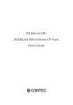
4.1 Capabilities Tab
The Capabilities Tab, shown in Figure 4-1, provides the following basic link
status and settings for the KS8841/2.
•
Link Status section shows the current link speed, duplex, MDI/MDIX and
polarity settings of the KS8841/2.
If there is no link, these four
fields are dimmed to indicate no status.
•
Advertised Capabilities and Link Partner Capabilities sections show
the speed, duplex and full duplex flow control capabilities of the
KS8841/2
and
its
link
partner.
KS8841/2
capabilities
are
programmable. Its link partner capabilities are read only, and dimmed
to indicate no capabilities when there is no link.
•
Crossover option allows the PHY to be set in HP Auto-MDIX for
automatic detection and correction for straight through and crossover
cabling, or forced to either MDI or MDIX mode.
To read the latest PHY status, press the Refresh button.
To configure the PHY, set the desired settings and press the Update button.
Confidential Information
Rev. 1.0
2180 Fortune Drive, San Jose CA95131, USA• (408)944-0800 • http://www.micrel.com
- Page 18 © 2006 Micrel Semiconductor
KS884x 16Bit BSP User’s Manual
Figure 4-1: LinkMD - Capabilities Tab
Confidential Information
Rev. 1.0
2180 Fortune Drive, San Jose CA95131, USA• (408)944-0800 • http://www.micrel.com
- Page 19 © 2006 Micrel Semiconductor
KS884x 16Bit BSP User’s Manual
4.2 Diagnostics Tab
The Diagnostics Tab provides the menu page to check the cable status and the
integrity of transmit and receive datapaths. These two selections are
provided by the cable diagnostic test and the TX/RX traffic test,
respectively.
Cable Diagnostic Test
The cable diagnostic test is enabled only when there is no link to the
KS8841/2 PHY. This test provides the following cable information for the
differential pairs connected to pins {1,2} and {3,6} of the RJ-45 jack.
•
Status:
•
Length:
Indicates whether the differential pair is Open, Short, or
Unknown (no link and no cable test conducted). If there
is a physical link, Status is Good.
Provides approximate distance in meters to the open or
short cable fault. If there is a physical link, Length has
no meaning and displays an empty field.
To run the cable diagnostic test, press the Test button.
Figure 4-2 shows the sample test results of the cable diagnostic test where
a 4 meters short and 3 meters open were found on the differential pairs
connected to pins {1,2} and {3,6} of the RJ-45 jack, respectively.
Confidential Information
Rev. 1.0
2180 Fortune Drive, San Jose CA95131, USA• (408)944-0800 • http://www.micrel.com
- Page 20 © 2006 Micrel Semiconductor
KS884x 16Bit BSP User’s Manual
Figure 4-2: LinKMD – Diagnostics (Cable Status) Tab
Confidential Information
Rev. 1.0
2180 Fortune Drive, San Jose CA95131, USA• (408)944-0800 • http://www.micrel.com
- Page 21 © 2006 Micrel Semiconductor
KS884x 16Bit BSP User’s Manual
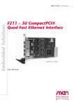
4.3 TX/RX Traffic Test
The TX/RX traffic test uses Ethernet packets to check the integrity of
transmit and receive datapaths. This test requires the KS8841/2 PHY to have
a physical link established with a PHY on the PC that is connected to the
KS8841/2 via RS232 Serial interface, as shown in
Figure 4-3.
KS8841 or KS8842 Demo Board
RS232 Cable
192.168.1.10
Port1
Ethernet Cable
192.168.1.1
Figure 4-3: TX/RX Traffic Test Setup
The PC should be connected to only two PHYs. One is the KS8841/2 via RS232
serial interface; and the other could be either a PHY on the motherboard or
a network interface card (NIC). The PHYs should be configured with
different static IP addresses under the same subnet. See section 4-3 on how
to configure network settings for Windows XP.
The Cable Status field at the top of this menu page displays the cable link
status of the KS8841/2. Before starting the TX/RX traffic test, press the
Refresh button to check the latest cable status. If there is a link, the
status will display either Crossed for a crossover connection or Good for a
straight connection. If there is no link, the status will display Unknown.
For the test setup in
Figure 4-3, the TX/RX counters and Send button at the bottom left of this
menu page are associated with the KS8841/2 PHY. Similarly, the TX/RX
counters and Send button at the bottom right of this menu page are
associated with the other PHY.
The drop down menu between the TX/RX counters selects the number of Ethernet
packets to send. The selections are 1, 10, 100, 1000, or Continuous.
The Send buttons start the transmission of packets with respect to either
KS8841/2 PHY or other PHY. The sample test results in 4-4 shows 100 packets
sent by the KS8841/2 PHY and 100 packets received by other PHY. Also, all
100 packets sent by the other PHY are received the KS8841/2 PHY. Note, if
Confidential Information
Rev. 1.0
2180 Fortune Drive, San Jose CA95131, USA• (408)944-0800 • http://www.micrel.com
- Page 22 © 2006 Micrel Semiconductor
KS884x 16Bit BSP User’s Manual
the PC is sending ARP packets or other Ethernet traffic is present, the
transmit count and receive count may differ.
Confidential Information
Rev. 1.0
2180 Fortune Drive, San Jose CA95131, USA• (408)944-0800 • http://www.micrel.com
- Page 23 © 2006 Micrel Semiconductor
KS884x 16Bit BSP User’s Manual
Figure 4-4: LinkMD – Diagnostics (Traffic Test) Tab
Confidential Information
Rev. 1.0
2180 Fortune Drive, San Jose CA95131, USA• (408)944-0800 • http://www.micrel.com
- Page 24 © 2006 Micrel Semiconductor
KS884x 16Bit BSP User’s Manual
5 KS8841/2 BSP Installation
This section describes how to install, and build KS8841/2 BSP under Renesas
HEW Version 3.01.05 / OpenTCP 1.04 for Renesas M16C/62P.
Before install KS8841/2 BSP, The Renesas SKP16C62P StarterKit Plus (SKP)
CD6 for M16C/62P must be installed on the host system (Microsoft Windows).
→ Note: The SKP kit comes with an integrated software development
environment, HEW (IDE, C-compiler, assembler, and linker), KD30
Debugger, and FoUSB (Flash-over-USB™) Programmer.
→ NOTE:
For more detail information about HEW, see the
SKP16C62P_Tutorial_1_HEW from Renesas.
The ks88xx_v1.0.0 SW Driver.zip ZIP file under directory “Software\M16C
software\Driver” contains:
o
OpenTCP protocol stack, and demo program.
o
BSP functions including UART driver, LCD driver etc.
o
KS8841 or KS8842 Ethernet driver.
o
Windows TCP GUI demo program.
o
Windows LinkMD GUI demo program.
5.1 Creating a KS884x BSP Directory
Create a KS884x directory under installDir (eg. MTOOL\ks884x), and copy the
ks884x.zip to MTOOL\ks884x. Unzip ks884x.zip under MTOOL\ ks884x directory.
It is successful if you see a new the directory MTOOL\ks884x\OpenTCP_104.
The most of subdirectories and files are the same as you download from
OpenTCP website, the KS8841/2 BSP only add or modify following
subdirectories and files:
Directory
Status
ks884x\OpenTCP_104\ks884x\ethernet_ks884x.c
Add
ks884x\OpenTCP_104\gui_demo.c
Modify
ks884x\OpenTCP_104\arch\M16C\set30_62pskp.inc
Modify
ks884x\OpenTCP_104\ks884x
Add
ks884x\OpenTCP_104\arch\uart
Add
6
Description
OpenTCP Ethernet Driver for Micrel
KS8841/2 device.
Change target IP to 192.168.1.1.
Init UART driver, and polling UART
receive.
Change the ISP in vector table to
ks884xIntr ISP.
This directory contains the KS8841/2
driver.
This directory contains UART driver
and CLI parser.
Please contact Renesas support on how to get SKP CD via the website www.renesas.com .
Confidential Information
Rev. 1.0
2180 Fortune Drive, San Jose CA95131, USA• (408)944-0800 • http://www.micrel.com
- Page 25 © 2006 Micrel Semiconductor
KS884x 16Bit BSP User’s Manual
6 Building KS8841/2 BSP from HEW
This section describes how to build KS8841/2 BSP for KS8841/2 demo board
from Renesas HEW project facility.
6.1 Starting HEW KS884x Project
To start HEW, from your development Windows PC, click on the
Start-> Programs -> Renesas High-performance Embedded Workshop -> Highperformance Embedded Workshop . After HEW opens, from the Welcome dialog box
(Figure 6-1-1), select “Browse to another project workspace” option, and
then click OK.
Figure 6-1-1: HEW Main Window
Then click on Browse, selection of Hew3 under
MTOOL\ks884x\OpenTCP_104\arch\M16C directory from the Workspace Browse
window (Figure 6-1-2).
Confidential Information
Rev. 1.0
2180 Fortune Drive, San Jose CA95131, USA• (408)944-0800 • http://www.micrel.com
- Page 26 © 2006 Micrel Semiconductor
KS884x 16Bit BSP User’s Manual
Figure 6-1-2: HEW Workspace Browse Window
HEW workspace should look like the figure 6-1-3 below.
Figure 6-1-3: HEW Workspace
Confidential Information
Rev. 1.0
2180 Fortune Drive, San Jose CA95131, USA• (408)944-0800 • http://www.micrel.com
- Page 27 © 2006 Micrel Semiconductor
KS884x 16Bit BSP User’s Manual
6.2 Build KS8841/2 BSP from HEW
If need to rebuild the KS8841/2 BSP from HEW, click on the ‘Build All’ icon.
This will re-compile and link all the source files.
Status, errors, messages, etc during a build process is displayed on the
Output window (Figure 6-2-1).
Figure 6-2-1: HEW Workspace with Output window
6.3 Build KS8842 BSP
To rebuild the KS8842 BSP from HEW, click on the ‘Options -> Renesas M16C
Standard Toolchain’.
From ‘C -> Defines’, add DEF_KS8842 1, then Build All’(Figure 6-3-1).
Now an executable file OpenTCP_M16C62P.mot has been created in the
MTOOL\ks884x\OpenTCP_104\arch\M16C\M16C62P_Release directory.
→ NOTE: Rename OpenTCP_M16C62P.mot to OpenTCP_M16C62P_ks8842.mot.
Confidential Information
Rev. 1.0
2180 Fortune Drive, San Jose CA95131, USA• (408)944-0800 • http://www.micrel.com
- Page 28 © 2006 Micrel Semiconductor
KS884x 16Bit BSP User’s Manual
Figure 6-3-1: Renesas M16C Standard Toolchain window to build KS8842 BSP
6.4 Build KS8841 BSP
To rebuild the KS8841 BSP from HEW, click on the ‘Options -> Renesas M16C
Standard Toolchain’.
From ‘C -> Defines’, add DEF_KS8841 1, then Build All’(Figure 6-4-1).
Now an executable file OpenTCP_M16C62P.mot has been created in the
MTOOL\ks884x\OpenTCP_104\arch\M16C\M16C62P_Release directory.
→ NOTE: Rename OpenTCP_M16C62P.mot to OpenTCP_M16C62P_ks8841.mot.
Confidential Information
Rev. 1.0
2180 Fortune Drive, San Jose CA95131, USA• (408)944-0800 • http://www.micrel.com
- Page 29 © 2006 Micrel Semiconductor
KS884x 16Bit BSP User’s Manual
Figure 6-4-1: Renesas M16C Standard Toolchain window to build KS8841 BSP
Confidential Information
Rev. 1.0
2180 Fortune Drive, San Jose CA95131, USA• (408)944-0800 • http://www.micrel.com
- Page 30 © 2006 Micrel Semiconductor
KS884x 16Bit BSP User’s Manual
7 Downloading (re-loading) the Firmware Program
Updating the KS8841/2 BSP is currently possible done by FoUSB (Flash-OverUSB™). FoUSB along with the ICD (RTA-FoUSB-MON) to download (reprogramming)
the M16C/62P flash MCU with firmware.
Before downloading the demo program, First, Renesas FoUSB has been installed
in your host system (Microsoft Windows)7.
Seconds, connect the RTA-FoUSB-MON (ICD) to your host system and to your
KS8841/2 demo board (Figure 7-1).
Figure 7-1: M16C/62P System Connectivity for FoUSB programmer
→ IMPORTANT! When using RTA-FoUSB-MON connect to the KS8841/2 demo board,
switch the power source switch on the RTA-FoUSB-MON to “TARGET” Powered
Mode since the power supply on the KS8841/2 demo board will provide power
to the KS8841/2 demo board as well as the RTA-FoUSB-MON. If the switch is
left at “USB” Powered Mode, some MCU pins may be driven to undesirable
levels.
7.1 Running FoUSB Programmer
Apply the 5V power supply to External Power Input on the KS8841/2 demo
board. Click on Start -> Programs -> Renesas-Tools -> Flashover-USB Ver.
2.01. -> FoUSB Programmer and a screen similar to Figure 7-1-1 will be
displayed.
7
Please reference the RTA-FoUSB-MON_Users_Manual for how to install FoUSB ICD.
Confidential Information
Rev. 1.0
2180 Fortune Drive, San Jose CA95131, USA• (408)944-0800 • http://www.micrel.com
- Page 31 © 2006 Micrel Semiconductor
KS884x 16Bit BSP User’s Manual
Figure 7-1-1 Example of FoUSB Programmer Screen with KS8841/2 demo board Connected
7.2 Downloading KS8841/2 BSP
To download the KS8841/2 BSP, perform following steps:
1. Click on OPEN on FoUSB main GUI. Windows file selection menu appears
as shown in Figure 7-2-1.
2. Find the demo file (e.g., OpenTCP_M16C62P_ks8842_v0.1.11.mot for
KS8842, and OpenTCP_M16C62P_ks8841_v0.1.11.mot for KS8841) for loading
into MCU flash. The selected target file appears on FoUSB main GUI
beside FILE as shown in Figure 7-2-2.
3. Click on PROGRAM on FoUSB main GUI. The Program Flash dialog box
appears as shown in Figure 7-2-3.
4. Click on Program of the Program Flash GUI. The loading of target
program into MCU flash will start at this point and the progress of
flash programming will be shown dynamically by a moving bar located at
the lower part of this dialog box. After a successful programming of
the flash, a Program Completed Successfully dialog box will appear.
5. Click on OK button and the dialog box disappear.
6. Click on EXIT button on the lower right corner of the main GUI to exit FoUSB
Programmer.
Confidential Information
Rev. 1.0
2180 Fortune Drive, San Jose CA95131, USA• (408)944-0800 • http://www.micrel.com
- Page 32 © 2006 Micrel Semiconductor
KS884x 16Bit BSP User’s Manual
→ Note:
Select Erase->Program->Verify option (the default option) from Choose an Operation.
Select Erase Only Needed Blocks option from Erasing Options.
Figure 7-2-1
Figure 7-2-2
Dialog box for file selection
FoUSB main GUI after file selection
Confidential Information
Rev. 1.0
2180 Fortune Drive, San Jose CA95131, USA• (408)944-0800 • http://www.micrel.com
- Page 33 © 2006 Micrel Semiconductor
KS884x 16Bit BSP User’s Manual
Figure 7-2-3 Menu options for programming flash
Confidential Information
Rev. 1.0
2180 Fortune Drive, San Jose CA95131, USA• (408)944-0800 • http://www.micrel.com
- Page 34 © 2006 Micrel Semiconductor