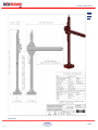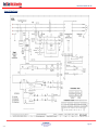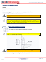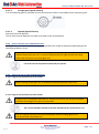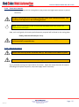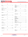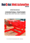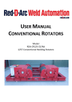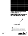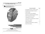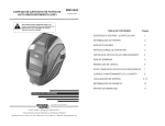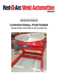
1
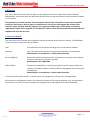
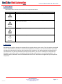
Column & Boom Model HD USER M ANUAL COLUMN & BOOM Model Heavy Duty HD-UL 16ft x 16ft Fixed Base For use with products having Serial Number 07248 and following Column & Boom Model HD 16ft x 16ft TABLE OF CONTENTS TABLE OF CONTENTS ......................................................................................................................................................2 1.0 Preface ........................................................................................................................................................ 4 1.1 Using This Manual ................................................................................................................................... 4 1.2 Safety Notices ......................................................................................................................................... 5 1.3 Disclaimer................................................................................................................................................ 5 2.0 Introduction ................................................................................................................................................ 6 2.1 Purpose and Function of a Column & Boom Manipulator ..................................................................... 6 2.2 Nomenclature Used in this Manual ........................................................................................................ 6 3.0 Safety .......................................................................................................................................................... 7 3.1 Introduction ............................................................................................................................................ 7 3.2 Safety Rules ............................................................................................................................................. 7 3.3 Users ....................................................................................................................................................... 7 3.4 Workspace .............................................................................................................................................. 8 3.5 Emergency Stops ..................................................................................................................................... 8 3.6 Non Compliant Operation ....................................................................................................................... 9 3.7 Warning Signs ......................................................................................................................................... 9 3.8 Emission and Environmental Information .............................................................................................. 9 4.0 Operating Instructions .............................................................................................................................. 10 4.1 Machine Details .................................................................................................................................... 10 4.2 Control Panel......................................................................................................................................... 10 4.3 Pendant ................................................................................................................................................. 11 4.4.1 Set UP ................................................................................................................................................. 12 STAGE 1 .................................................................................................................................................................. 12 STAGE 2 .................................................................................................................................................................. 12 STAGE 3 .................................................................................................................................................................. 13 STAGE 4 .................................................................................................................................................................. 13 STAGE 5 .................................................................................................................................................................. 14 STAGE 6 .................................................................................................................................................................. 14 STAGE 7 .................................................................................................................................................................. 15 4.5.1 Switching On ...................................................................................................................................... 15 4.5.2 Operating the Column & Boom ......................................................................................................... 15 4.5.3 Welding .............................................................................................................................................. 16 4.5.4 Stopping the Column & Boom ........................................................................................................... 16 Red D Arc Welderentals Version v1.0 667 South Service Rd., Grimsby, ON L3M 4G1 Phone: 905.643.4910 Efax: 905.963.7810 Website: reddarc.com Page - 2 - Column & Boom Model HD 16ft x 16ft 4.6 Common Mistakes When Using Column & Booms............................................................................... 16 4.7 Breakdowns........................................................................................................................................... 17 4.8 Cleaning................................................................................................................................................. 17 5.0 Maintenance and Servicing....................................................................................................................... 18 5.1 General .................................................................................................................................................. 18 5.2 Installation ............................................................................................................................................ 18 5.3 Storage .................................................................................................................................................. 18 5.4 Repair and Maintenance ....................................................................................................................... 19 5.5 Repairs and Replacement Parts ............................................................................................................ 19 6.0 Replacement Parts .................................................................................................................................... 20 6.1 MECHANICAL PARTS LIST ...................................................................................................................... 20 6.2 ELECTRICAL PARTS LIST ......................................................................................................................... 21 Appendix A – Overview Drawing ................................................................................................................ 22 Appendix B – Wiring Diagram ......................................................................................................................... 23 Appendix C – Inverter Parameter Settings ..................................................................................................... 24 Appendix D – Gearbox Maintenance .............................................................................................................. 25 D.1 Measures before start-up ................................................................................................................ 25 D.1.1 Oil level check ............................................................................................................................... 25 D.1.1.1 Checking the oil level in the gear unit housing ......................................................................... 25 D.1.2 Startup without long term preservation ...................................................................................... 26 D.1.3 Startup in case of long term preservation .................................................................................... 26 D.1.3.1 Long term preservation up to 18 months ............................................................................................. 26 D.1.3.2 Long term preservation up to 36 months ............................................................................................. 26 D.1.4 Filling with lubricant ..................................................................................................................... 27 D.1.5 Drive with backstop ...................................................................................................................... 27 D.2 D.2.2 Maintenance and repair ................................................................................................................... 28 Description of maintenance and repairs ...................................................................................... 29 Appendix E.1 – CE Certificate of Conformity .................................................................................................. 33 E.2 UL Listing .......................................................................................................................................... 34 E.3 CAS Listing ........................................................................................................................................ 35 Table of Illustrations ....................................................................................................................................... 36 Red D Arc Welderentals Version v1.0 667 South Service Rd., Grimsby, ON L3M 4G1 Phone: 905.643.4910 Efax: 905.963.7810 Website: reddarc.com Page - 3 - Column & Boom Model HD 16ft x 16ft 1.0 PREFACE This user’s manual describes the everyday use and maintenance of our Heavy Duty Column & Boom Manipulators. Any actions that are required to be carried out by the manufacturer have not been included in this manual. This manual is part of the machine. Please keep this manual safe. Information in this manual could be useful at a later time or when a repair or maintenance is carried out. We suggest that a copy of the manual is made and kept with the machine; the original should be kept in a safe place. If necessary, replacement copies can be supplied. If the machine is sold at a later date then the manual should be also supplied with it to the new user. 1.1 USING THIS MANUAL The instruction in this manual are arranged for various personnel at the end users factory. The definitions in this manual, for these users are as follows; User : The collective term for anyone working at or on the column & boom. Operator: This is the person that operates or drives the machinery on a daily basis. Read Chapters: 2 Introduction, 3 Safety and 4 Operation. Service Engineer Personnel trained and experienced in maintenance and repair of mechanical or electrical elements of machine systems. Read Chapters: ALL CHAPTERS Safety Officer The person responsible for site safety procedures at the location where the rotators are installed. Where no Safety Officer is designated, then this will be the employer. Read Chapters: 2 Introduction, 3 Safety and 4 Operation In this manual the word “vessel” is used to mean any component or device that is being welded. All the pictures and diagrams used in this manual are purely for illustrative purposes only, to help explain instructions in the text. The actual equipment supplied may deviate slightly from those illustrated. Red D Arc Welderentals Version v1.0 667 South Service Rd., Grimsby, ON L3M 4G1 Phone: 905.643.4910 Efax: 905.963.7810 Website: reddarc.com Page - 4 - Column & Boom Model HD 16ft x 16ft 1.2 SAFETY NOTICES The following Safety notices in this document are organized as follows: Safety notice I Description Disregarding the safety regulations and guidelines can be life-threatening. Danger! ! Disregarding the safety regulations and guidelines can result in severe injury or heavy damage to the column & boom and/or vessel. Warning! $ Disregarding the safety regulations and guidelines can result in injury or damage to the column & boom and/or vessel. Caution! Important information used to prevent errors. Information: 1.3 DISCLAIMER We reserve the right to change the content of this manual without prior notice. The information contained herein is believed to be accurate as of the date of publication, however, Key Plant Automation Ltd, makes no warranty, expressed or implied, with regards to the products or the documentation contained within this document. Key Plant Automation Ltd. shall not be liable in the event if incidental or consequential damages in connection with or arising from the furnishing, performance or use of these products. The software names, hardware names and trademarks used in this document are registered by the respective companies. Red D Arc Welderentals Version v1.0 667 South Service Rd., Grimsby, ON L3M 4G1 Phone: 905.643.4910 Efax: 905.963.7810 Website: reddarc.com Page - 5 - Column & Boom Model HD 16ft x 16ft 2.0 INTRODUCTION 2.1 PURPOSE AND FUNCTION OF A COLUMN & BOOM MANIPULATOR The column & boom manipulator is designed to aid the welding of vessels both longitudinally and circumferentially. By using the motors to raise and lower the boom and also to drive the boom forwards and backwards, the weld head mounted at the end of the boom can be correctly positioned for the required weld. 2.2 NOMENCLATURE USED IN THIS MANUAL Below are listed explanations of commonly used phrases used in this manual. Column Vertical axis of the column and boom Boom Horizontal axis of the column & boom Base The floor mounting plate Slewing Ring Ring bearing that the column is bolted to on the base. Panel Electrical control box mounted on the Column Pendant Operators hand control Pendant Red D Arc Welderentals Version v1.0 667 South Service Rd., Grimsby, ON L3M 4G1 Phone: 905.643.4910 Efax: 905.963.7810 Website: reddarc.com Page - 6 - Column & Boom Model HD 16ft x 16ft 3.0 SAFETY 3.1 INTRODUCTION The column & boom has been designed and manufactured in such a way that it can be used and maintained safely. This relies on following the instructions as detailed in this manual, therefore it is necessary for anyone working with or on this machine to have read this manual. 3.2 SAFETY RULES Ensure that children or animals do not have access to the machinery at any time. Any safety items fitted, must not be bypassed, or removed. If they have to be removed then the equipment must be put out of operation, until a repair is completed. Always keep the workplace clean and free from obstacles. Make sure that the work area is well lit. Ensure that the machine is regularly maintained to ensure that it remains safe. 3.3 USERS OPERATORS The column & boom may only be operated by adults, who have read and understood this manual, in particular the sections on Safety and Operating Instructions. Specialised training is not necessary, but experience in working with this kind of equipment is required. The tasks of the operator will include; Raising and lowering the boom to the correct working height for the weld head. Moving the boom forward and backward to position head correctly for welding. Setting the speed of the boom forward/reverse travel, for welding longitudinally. Daily Maintenance Checks Observing the column & boom while it is operating. Keeping the column & boom clean. SERVICE ENGINEERS Service Engineers must be aware of the extra risks when working on the machine. As well as the above knowledge for operators, the service engineer must also; Have received the required training/education or knowledge as necessary for the local regulations regarding service engineers. Must have experience in maintaining and servicing machinery. Have access to correct tools required to service/repair the machinery. Red D Arc Welderentals Version v1.0 667 South Service Rd., Grimsby, ON L3M 4G1 Phone: 905.643.4910 Efax: 905.963.7810 Website: reddarc.com Page - 7 - Column & Boom Model HD 16ft x 16ft 3.4 WORKSPACE ! By this we mean a clear space around the column & boom. The free space required around the column & boom should be based on a circle with the column at the centre. The radius of the circle being scribed is when the boom is fully forward, i.e. welding head at the furthest point from the column. From within the workspace all operations and servicing can be carried out. Ensure that any protrusions on the vessel cannot cause any injury or damage. 3.5 EMERGENCY STOPS I It is vitally important for the safety of the operators and any other personnel in the area of the rotators, that the operator fully understands the location and how to use the emergency stop buttons on the machine. It is also recommended that other personnel that work in the vicinity of the rotators are also aware of the positions of emergency stop buttons, so they can stop the equipment if the operator requires assistance or is trapped. Firstly all new operators should be made aware of these emergency stop procedures. There are two emergency stop buttons fitted on the column & boom, one is located on the panel mounted on the column, on the on the operators control stand. Pressing either of these two buttons will immediately bring the column & boom to a stop, and all controls will be locked. In case of personal injury, help can be given immediately, also if there is other urgent action required this can be carried out immediately. After the hazard has been resolved and after checking the machine can be safely operated again, the emergency stop button needs to be released by twisting it in the direction of the arrows printed on it. Once this is done, normal operation will continue. Note either emergency stop button can be used to stop the machine but operation can only restart again once the reset button is pressed. I We recommend New operators are allowed to practise with the emergency stop switches The Emergency Stop is tested at the start of every shift NEVER DISCONNECT OR BYPASS THE EMERGENCY STOP BUTTONS Red D Arc Welderentals Version v1.0 667 South Service Rd., Grimsby, ON L3M 4G1 Phone: 905.643.4910 Efax: 905.963.7810 Website: reddarc.com Page - 8 - Column & Boom Model HD 16ft x 16ft 3.6 NON COMPLIANT OPERATION ! The column & boom is not suitable for the following types of operations. Carrying any weight on the boom that is greater than the SWL for the machine. Operating the machine on any kind on incline. In addition the following is also prohibited; The mounting of additional controls which are not approved by the manufacturer. 3.7 WARNING SIGNS On the machines there will be various warning signs. These should be checked to ensure that they remain visible and readable at all times. If necessary order replacements. ! Warning symbols are on the machine for a reason. Check them regularly to ensure they are always affective. 3.8 EMISSION AND ENVIRONMENTAL INFORMATION The column & boom itself does not contain substances that are dangerous to humans. There are no specific dangers in the operation, maintenance or dismantling of this machinery regarding the environment. In the event of a fire standard fire extinguishing equipment may be used as suitable. Red D Arc Welderentals Version v1.0 667 South Service Rd., Grimsby, ON L3M 4G1 Phone: 905.643.4910 Efax: 905.963.7810 Website: reddarc.com Page - 9 - Column & Boom Model HD 16ft x 16ft 4.0 OPERATING INSTRUCTIONS Before operating the column & boom please ensure that you have read Chapter 2 – “Safety”. This chapter of the manual is meant for the operators, though all people concerned with the machines should read it. 4.1 MACHINE DETAILS The column & boom will usually consist of a column, a boom and a base. The column is supplied complete with the boom carriage mounted onto it. The carriage is driven via a rack and pinion up and down the carriage. A fail safe device is fitted to the carriage, so that if drive to the carriage brakes, and then the carriage will lock into position, preventing the boom from falling and causing injury. The boom is fitted with a rack, for drive via a pinion forwards and backwards. The motor is inverter controlled so that the speed of the boom may be varied The base is fitted with a ring bearing that allows the column to rotate through 360 around its vertical axis. On the base are also clamps so that the column can be locked into the desired position. 4.2 CONTROL PANEL The control panel on the column has the following controls; 1. Power On Lamp 2. Emergency Stop Reset Button – After an Emergency Stop or when first powering up, this button must be pressed, before the machine will operate. Once pressed and the machine is ready the button will illuminate. 3. Boom Up Button 4. Boom Down Button 5. Emergency Stop Button 6. Panel door opening key 7. Door electrical isolator, must be turned off before panel door can open. 1 2 3 4 5 6 7 Figure 1 Main Panel Red D Arc Welderentals Version v1.0 667 South Service Rd., Grimsby, ON L3M 4G1 Phone: 905.643.4910 Efax: 905.963.7810 Website: reddarc.com Page - 10 - Column & Boom Model HD 16ft x 16ft 4.3 PENDANT The hand pendant has the following controls Boom Elevation push buttons, Up (white) and Down (black). Note these are hold to run, as soon as the operator releases the button the boom elevation travel will stop. Boom direction push buttons, forward (yellow), reverse (green) and stop (red). Note as soon as one of the direction buttons (Forward or Reverse) are pressed then the boom will begin to travel. The operator can release the button and the boom continues to travel. To stop press the red button. Boom Speed Control Potentiometer. Turning the knob clockwise increases the rotator speed, and conversely rotating anticlockwise decreases the speed. Figure 2 Hand Control Pendant Red D Arc Welderentals Version v1.0 667 South Service Rd., Grimsby, ON L3M 4G1 Phone: 905.643.4910 Efax: 905.963.7810 Website: reddarc.com Page - 11 - Column & Boom Model HD 16ft x 16ft We recommend that the operator always presses stop, before changing the travel direction of the boom. 4.4.1 SET UP The following stages of assembly must be followed in order to ensure that the machine is correctly commissioned. Column & Booms are dismantled prior to shipment with the base, column and boom being forwarded with adequate protection or packing for overseas shipments. Furthermore, the machine is dismantled in such a way as to minimise the assembly work at site. STAGE 1 Remove all anti-corrosion protection from the machine slide-ways, rollers etc. Light oil may be applied to these slide-ways to prevent discolouration. FIXED BASE: Locate the base on perfectly flat floor area and check with spirit level on rotating or fixed centre. TRAVERSING BOGIE: Track should be provided using correct rail section and laid perfectly flat and parallel at required track gauge. The four wheels must always be in contact with the rails to ensure stability and smooth traverse. For traversing bogies with 2 double flanged and 2 plain wheels, the rail for the double flanged must be flat and perfectly straight. The other rail should be flat, and near parallel as possible. Lock the rotating centre of the slewing ring on the base and clean its surface of anticorrosive. STAGE 2 Heavy Duty Columns are despatched from our factory with two safety bars through the column, to prevent the counterweight moving inside during transit. The Safety Bars should not be removed until the Column has been raised by overhead crane and bolted to the fixed base or traversing bogie. Red D Arc Welderentals Version v1.0 667 South Service Rd., Grimsby, ON L3M 4G1 Phone: 905.643.4910 Efax: 905.963.7810 Website: reddarc.com Page - 12 - Column & Boom Model HD 16ft x 16ft STAGE 3 The Column may now be raised by overhead or mobile crane using the lifting eyes at the top of the Column. ! Care should be taken when raising the Column to avoid the Column swinging and becoming a hazard and possibly causing injury to persons in the vicinity or other items of infrastructure or the machine itself. Remove the section of channel bolted to the bottom of the Column. Clean the Column flange and lower Column on to the traversing bogie/fixed base and securely bolt in position. The carriage securing bracket may now be removed. This bracket is located on the underside of the carriage and is painted yellow. STAGE 4 Remove from the opposite end of the boom, from where the weld head will be located, the traverse limit cam. Also remove the wire reel bracket from the end of the boom if supplied. Remove wooden cone from end of insulated tube, also if supplied. Remove aluminium grommet from side of boom. Ensure that the top rollers on the carriage are fully raised in order to give maximum clearance when feeding the Boom into the carriage. Release the double lock nuts on the roller shafts and turn the eccentric shafts until the roller is in the highest position. The eccentric roller shafts may be turned in either direction. Raise the Boom by crane and feed the end of the Boom, which has had the cam removed into the carriage. When the Boom is halfway through the carriage and resting on the bottom rollers, lower the top rollers until they are contact with the slides and then lock the two nuts on each eccentric roller shaft. Red D Arc Welderentals Version v1.0 667 South Service Rd., Grimsby, ON L3M 4G1 Phone: 905.643.4910 Efax: 905.963.7810 Website: reddarc.com Page - 13 - Column & Boom Model HD 16ft x 16ft $ DO NOT over tighten the eccentric rollers on the boom this is unnecessary and will overload the Boom drive motor. STAGE 5 Refit the boom traverse limit cam, wooden cone and wire reel bracket if supplied with machine. Also refit the aluminium grommet which is essential if the cables are not to be chafed. The Boom traverse drive baseplate may now be fitted to the carriage, but ensure that the spur gear meshes correctly with the rack on the side of the Boom. If a welding head control box support cabinet has been supplied this may now be fitted at the end of the boom. The welding head may also be mounted together with cross slides, if supplied. If the main control panel has been removed, to ensure safe transportation to site then this should now be mounted at the rear of the Column. In addition, the cable carrier bracket should also be fitted at the rear of the Column nut, above the main control panel. If a welding rectifier or generator support platform has been supplied for the machine, this may now be bolted in position on the side of the Column. STAGE 6 The machine is now fully assembled and may be wired in accordance with the schematic diagram provided. The required mains power may now be connected to the column. When commissioning the machine the remote control speed potentiometers should be turned to a low speed setting i.e. turns anticlockwise. The forward or reverse pushbutton may now be pressed to start the boom or bogie traverse motion at a slow speed. The boom limits should be checked at low speed to ensure that they are capable of stopping the motor at maximum forward or reverse traverse. ! Very Important. Please ensure that the phases are wired correctly. This means that when the up button is pressed on the pendant and control box the carriage moves up. If the carriage moves down when the up button is pressed it means that the phases are wired incorrectly. Turn off the power supply and swap over any of the 2 phases to ensure that the carriage moves in the same direction as the pendant indicates. When the Column is working in this condition the limit will not stop the motor. The elevation limit switches should be checked by hand while the motor is being energised. Failure to comply with this will result in extreme damage to both the limit switches and the machine. On heavy duty columns, lower the carriage and raised the cast iron counterweight clear of the safety bar, the bar must then be removed from the column. Red D Arc Welderentals Version v1.0 667 South Service Rd., Grimsby, ON L3M 4G1 Phone: 905.643.4910 Efax: 905.963.7810 Website: reddarc.com Page - 14 - Column & Boom Model HD 16ft x 16ft STAGE 7 The Column and Boom should now function correctly and give satisfactory performance over long periods. It is recommended that gearbox oil levels are checked before being put into operation. Occasionally gearbox breather plugs are replaced by solid plugs to avoid oil spillage during transit. The correct breather plugs should be fitted. Always ensure that the carriage rollers are in contact with the slides and that the slides are kept clean and free of scale. 4.5.1 SWITCHING ON Before switching on the column & boom, check the following; Visually inspect the rollers, runners, motors, gearboxes, pendant, panel and cables for any signs of damage. Has the transport bar for the counterweight been removed? Are there any obstructions to prevent full travel of the boom up/down and in/out? Check column & boom rack and pinions are in mesh. ! WARNING! Do not operate the column & boom if there are signs of damage, always have a service engineer to check these over and make repairs if necessary. Once the operator is satisfied that the equipment is in good order, plug in the mains lead to the power supply. ! ! WARNING! Check that the mains power supply matches the electrical voltage shown on the panel. WARNING! Ensure that the mains and pendant cables, do not cross lanes where forklift trucks or other vehicles can run over them, and they do not create a tripping hazard. Switch on the mains power, and the Power On lamp on the control panel should illuminate. Check that the emergency stop buttons are not pressed in, and then press the reset button. The machine is now ready to operate. 4.5.2 OPERATING THE COLUMN & BOOM Ensure that there is nothing in the path of the column & boom when moving. The operator can use the UP and Down button on either the control panel or the pendant to set the correct height for the boom. The operator should then set the speed potentiometer knob (see figure 2) to the desired speed of the boom horizontal travel. Red D Arc Welderentals Version v1.0 667 South Service Rd., Grimsby, ON L3M 4G1 Phone: 905.643.4910 Efax: 905.963.7810 Website: reddarc.com Page - 15 - Column & Boom Model HD 16ft x 16ft Then press the desired travel direction (GREEN or YELLOW button) the boom will then start to move off in the desired direction. 4.5.3 WELDING It is important that the user is aware of the earthing requirements of their welding procedure, and that this is correctly connected to the vessel before welding. ! WARNING! The column & boom is insulated from the welding equipment and welding wire. It is important to ensure the insulated ducting for the welding wire and also insulation at the points where the welding equipment is bolted to the boom are in good condition at all times It is good practise to keep the column & boom clean. Any arc sparks, flux or slag that falls onto the machine should be removed as soon as is possible. 4.5.4 STOPPING THE COLUMN & BOOM To stop the boom, press the RED stop button on the hand pendant. This will stop boom travel, which will not restart until a direction button is pressed. If necessary the column & boom can be stopped using the Emergency Stop Button on either the panel or hand pendant. This should only be used in an emergency. 4.6 COMMON MISTAKES WHEN USING COLUMN & BOOMS 1. Over-tightening the rollers on the boom. This will cause the motor to become overloaded and the inverter will trip. 2. Parts of the vessel come into contact with the boom in the vicinity during rotation. This can cause damage to the column & boom and welding heads. 3. Emergency Stop button is depressed. If a switch is pressed in, the operator must find out who pressed it in and for what reason, before restarting the machine. There may be a hazard that someone else has seen and stopped the machine for. 4. The phases of the electrical supply are incorrect for the operation of the machine. It must be checked for both up and down travel of the boom and horizontal travel of the boom, that the limit switch for the direction that the boom is travelling in stops the boom. If it does not then the phases will need swapping over. Red D Arc Welderentals Version v1.0 667 South Service Rd., Grimsby, ON L3M 4G1 Phone: 905.643.4910 Efax: 905.963.7810 Website: reddarc.com Page - 16 - Column & Boom Model HD 16ft x 16ft 4.7 BREAKDOWNS If the column & boom stops working, then the equipment must only be repaired by qualified service personnel. If there are repeat faults, then this could indicate a problem with the machine. Inform the person on site that is responsible for service and maintenance. 4.8 CLEANING The column & boom require no special cleaning instructions. The machine should not create any pollution to the environment around them during normal operation, although, the welding process being carried out on them may pollute the rotators. ! It is good practice to keep the column & boom clean. Any arc sparks, flux or slag that falls onto the machine should be removed as soon as is possible. WARNING! Column & boom must be electrically isolated before cleaning. Any electrical components must not come in contact with water or other cleaning fluids. Red D Arc Welderentals Version v1.0 667 South Service Rd., Grimsby, ON L3M 4G1 Phone: 905.643.4910 Efax: 905.963.7810 Website: reddarc.com Page - 17 - Column & Boom Model HD 16ft x 16ft 5.0 MAINTENANCE AND SERVICING This chapter should be read by all service engineers that will be working on these rotators. 5.1 GENERAL ! ! WARNING! During all maintenance or repair procedures, the column & boom must be electrically isolated. Do this by switching off the main electrical supply and unplugging the mains cable. WARNING! After disconnecting the power there may be some residual charge in some components in the panel. Wait a few minutes after disconnecting the mains power before commencing work on any electrical elements of the machine. 5.2 INSTALLATION Before first use, or after maintenance or repair work, or after a period of the column & boom being in storage, they will need to go through this installation procedure. Before the column & boom was despatched from the factory, it will have been fully tested for correct functioning and therefore they can be directly put into operation without the need for any further test time. We would though recommend that the operations of all controls are tested before the equipment is put into the production process. Before starting up, check the following; All moving parts can freely move Check oil level in the gearbox (see appendix D for Lubrication of the gearboxes) Check the integrity of all cables, mains and hand control pendant, make sure there are no cuts etc. Check the hand pendant controls all operate correctly. Check the Emergency Stop on the Pendant works, and locks all other controls so the machine cannot restart then reset on the panel. Check the Emergency Stop on the Panel works, and locks all other controls so the machine cannot restart then reset on the panel. Check the steel framework to ensure it is straight and free from damage. 5.3 STORAGE There are no specific requirements for storage other than storing in a cool dry place. After a long period of storage the machines will need to be checked over thoroughly before being put into use again. ! WARNING! After storing or transporting the machine in a cold climate and moving it into a warm location, there may be a build up of condensation within the machine and electrical controls. To prevent damage, allow the machine to adjust to the new environment temperature. Red D Arc Welderentals Version v1.0 667 South Service Rd., Grimsby, ON L3M 4G1 Phone: 905.643.4910 Efax: 905.963.7810 Website: reddarc.com Page - 18 - Column & Boom Model HD 16ft x 16ft $ Do not store the machine outside unprotected. Equipment should be sheeted, and bare metal areas, bearings, gears and shafts suitably greased to prevent corrosion. 5.4 REPAIR AND MAINTENANCE The column & boom is designed and constructed to the highest standards, using high quality components. As such this equipment should expect to have many years of operational life with only a minimal amount of regular maintenance. To continue the longevity of the equipment, all efforts should be made to keep the column & boom clean and free from dirt or waste from the welding process. In addition the gearbox oil levels should be checked regularly and kept at the correct levels, see Appendix D, for more information on gearbox maintenance. At least once per year the whole installation should be inspected with particular attention paid to the following; Poor electrical contacts Switches and controls Loose mechanical parts, ensure all fixings are correctly tightened Check smooth running of boom both up/down and horizontal travel i.e. no vibrations Metal corrosion Frame damage Check for signs of damage to the roller bearings. Follow maintenance procedure for the gearboxes in Appendix D Check all cables for damage (mains, pendant and also any visible cable running from the panel to the motors). Check the emergency stops and also the correct functioning of the panel door isolator. Remove guards and check the condition of the spur gear and pinion on the boom and column drives. If there is any excessive damage then the parts should be removed and replaced with new. 5.5 REPAIRS AND REPLACEMENT PARTS During the warranty period repairs must only be carried out under the direction of the manufacturers. Any unauthorised repairs may damage the machine and invalidate the warranty. It is advised that the manufacturer should be contacted for the supply of all replacement parts; this will ensure that the correct part or suitable alternative parts are supplied and used on the equipment. Red D Arc Welderentals Version v1.0 667 South Service Rd., Grimsby, ON L3M 4G1 Phone: 905.643.4910 Efax: 905.963.7810 Website: reddarc.com Page - 19 - Column & Boom Model HD 16ft x 16ft 6.0 REPLACEMENT PARTS ! WARNING! Not following the recommendations for replacement parts in section 5.5 can have consequences for the safety of the equipment. The manufacturers cannot be held liable for any subsequent problems after fitting none recommended parts. 6.1 MECHANICAL PARTS LIST Part Number Main Sections Description Quantity KPHDUL0100 KPHDUL0200 KPHDUL0300 KPHDUL0400 Column Boom Base Carriage 1 1 1 1 Column Safety Rack Column Elevation Rack Elevation Gearbox Elevation Motor Elevation Gearbox Mounting Feet Elevation Pinion Column Limit Switches Column Strikers Carriage Bracket 1 1 1 1 1 1 2 2 1 Boom Rack Boom Gearbox Boom Gearbox Feet Boom Gearbox Adjuster Plate Boom Motor Boom Pinion Boom Shaft Boom Limit Switch Boom Striker Boom Cable Chain Cable Tray 1 1 1 1 1 1 1 2 2 1 1 Carriage Rollers Carriage Bearings Safety Device Assembly 8 8 1 Rotation Slewing Ring Base Clamps 1 3 Column KPHDUL0102 KPHDUL0108 KPHDUL0106 KPHDUL0107 KPHDUL0110 KPHDUL0111 KPHDUL0109 KPHDUL0112 KPHDUL0104 Boom KPHDUL0207 KPHDUL0202 KPHDUL0203 KPHDUL0204 KPHDUL0201 KPHDUL0205 KPHDUL0206 KPHDUL0208 KPHDUL0209 KPHDUL0222 KPHDUL0223 Carriage KPHDUL0401 KPHDUL0402 KPHDUL0403 Base KPHDUL0301 KPHDUL0302 Red D Arc Welderentals Version v1.0 667 South Service Rd., Grimsby, ON L3M 4G1 Phone: 905.643.4910 Efax: 905.963.7810 Website: reddarc.com Page - 20 - Column & Boom Model HD 16ft x 16ft 6.2 ELECTRICAL PARTS LIST 1 2 3 4 5 6 7 14 18 15 16 8 19 9 17 10 11 12 20 13 10 21 Figure 3 Panel Exterior Figure 5 Panel Interior Photo No. 1 2 3 4 5 6 7 8 9 10 11 12 13 14 15 16 17 18 19 20 21 Not Shown Part Number KP3006 KP1060 KP1020 KP1010 KP1030 KP1042 KP1004 KP1041 KP1008 KP1028 KP1002 KP1001 KP4001 KP1092 KP1091 KP1088 KP1090 KP1065 KP1095 KP2026 KP1075 KPPENCAB Description Boom Motor Inverter 3 Phase 0.37kw Relay 2 Pole Circuit Breaker 0.5A 1 Pole Circuit Breaker 3A Motor Circuit Breaker 1.6-2.5A 3 Pole Reversing Contactor 9A, 24VAC Transformer 415V:24V 63VA Contactor 9A, 24VAC 3 Phase Fuse Holders and Fuses 6A Fused Door Isolator Switch Terminals (Grey) Earth Terminals (Green/Yellow) 10 Way Earthing Bar Power On Lamp (White) Emergency Stop Reset Button (Blue) Panel Push Buttons (Black/White) Emergency Stop Button Pendant Body (6 Position) Pendant Pushbutton (White, Black, Yellow, Red, Green) Pendant Speed Potentiometer Pendant Emergency Stop Pushbutton Pendant Cable Red D Arc Welderentals Version v1.0 Figure 4 Control Pendant 667 South Service Rd., Grimsby, ON L3M 4G1 Phone: 905.643.4910 Efax: 905.963.7810 Website: reddarc.com Quantity 1 2 1 1 1 1 1 1 2 1 29 4 1 1 1 1 1 1 5 1 1 30m Page - 21 - Column & Boom Model HD 16ft x 16ft APPENDIX A – OVERVIEW DRAWING Figure 6 Overview Diagram Red D Arc Welderentals Version v1.0 667 South Service Rd., Grimsby, ON L3M 4G1 Phone: 905.643.4910 Efax: 905.963.7810 Website: reddarc.com Page - 22 - Column & Boom Model HD 16ft x 16ft APPENDIX B – WIRING DIAGRAM Red D Arc Welderentals Version v1.0 667 South Service Rd., Grimsby, ON L3M 4G1 Phone: 905.643.4910 Efax: 905.963.7810 Website: reddarc.com Page - 23 - Column & Boom Model HD 16ft x 16ft APPENDIX C – INVERTER PARAMETER SETTINGS The following settings have been programmed into the inverter at the factory; Parameter Number 1 2 3 4 6 Value 0 54 1 1 1.3 Parameter Number 10 11 22 Value L3 0 A All other values are as set by the inverter manufacturer and need not be altered. Red D Arc Welderentals Version v1.0 667 South Service Rd., Grimsby, ON L3M 4G1 Phone: 905.643.4910 Efax: 905.963.7810 Website: reddarc.com Page - 24 - Column & Boom Model HD 16ft x 16ft APPENDIX D – GEARBOX MAINTENANCE Startup D.1 MEASURES BEFORE START-UP D.1.1 OIL LEVEL CHECK Before connecting up the drive system to the current supply check the oil level or Shut down the gear unit by shutting off the drive unit ! D.1.1.1 WARNING! Secure drive unit to prevent accidental start-up. Affix notice at the switchon point. Note: In case of tandem gear units, each single gear unit should be inspected separately. Check oil level with the oil cooled down. Even after a short run, oil needs a longer ‘rest’ in order to release possible air bubbles. CHECKING THE OIL LEVEL IN THE GEAR UNIT HOUSING Screw out the plug screw at the point marked with this symbol. Note: If the oil level is correct, a small amount of oil may flow out; the oil must at least come up to the lower edge of the bore. ! Any oil escaping should be removed immediately with oil binding agent in an environmentally compatible way. For drives with only one plug screw, checking the oil level is not possible. Red D Arc Welderentals Version v1.0 667 South Service Rd., Grimsby, ON L3M 4G1 Phone: 905.643.4910 Efax: 905.963.7810 Website: reddarc.com Page - 25 - Column & Boom Model HD 16ft x 16ft D.1.1.2 Oil sight glass (Special feature) If an oil inspection glass is provided, the oil level must be visible in the middle of the inspection glass. D.1.1.3 Dipstick (Special feature) Check oil level with dipstick: The oil level must be between the lower and upper mark of the dipstick. D.1.2 STARTUP WITHOUT LONG TERM PRESERVATION MOTOX® drives are delivered with the appropriate lubricants ready for operation depending on the specified conditions of use. ! On gear systems with the required housing ventilation the required ventilator filter is delivered loose with the unit. It must be replaced with the appropriate screw plug before the initial start –up of the gear unit. It must be used at the position indicated by this symbol. D.1.3 STARTUP IN CASE OF LONG TERM PRESERVATION D.1.3.1 Long term preservation up to 18 months ! Before starting up the gear unit, it should be filled with lubricant (see D.1.4). D.1.3.2 Long term preservation up to 36 months ! The gear unit is completely filled with oil. Before the start up, the oil level should be corrected according to the type of construction. The oil level should be reduced to the level marked with this symbol (see D.1.1). ! Any oil escaping should be removed immediately with oil binding agent in an environmentally compatible way. Red D Arc Welderentals Version v1.0 667 South Service Rd., Grimsby, ON L3M 4G1 Phone: 905.643.4910 Efax: 905.963.7810 Website: reddarc.com Page - 26 - Column & Boom Model HD 16ft x 16ft D.1.4 FILLING WITH LUBRICANT ! Screw out venting screw or venting filter or plug screw at the highest point (see 3.2 or point of ventilation). Fill gear unit up with fresh oil using a filling filter (max. filter coarseness 60 µm). The quantity of oil depends on the mounting position! Note: Recommendations on the oil to be used should be taken from section 10. “Maintenance and repair.” Data, such as oil grade, oil viscosity and oil quantity required will be found on the rating plate Finally, check the oil level (see 7.1.1). ! Any oil escaping should be removed immediately with oil binding agent in an environmentally compatible way. D.1.5 DRIVE WITH BACKSTOP ! ! Secure drive unit to prevent accidental start-up. Affix notice at the switch-on point. Check the direction of rotation before putting into service! E.g. by manually turning the input shaft or the motor. Check the motor direction of rotation according to the phase sequence, swap two supply leads if necessary. Red D Arc Welderentals Version v1.0 667 South Service Rd., Grimsby, ON L3M 4G1 Phone: 905.643.4910 Efax: 905.963.7810 Website: reddarc.com Page - 27 - Column & Boom Model HD 16ft x 16ft D.2 MAINTENANCE AND REPAIR D.2.1 General Information on Maintenance ! All maintenance and repair work should be carried out with due care and only by thoroughly trained personnel. The periods listed in the table below, are largely dependent on the conditions of use of use of the gear unit. For this reason, it is only possible to give average periods which refer to a - Daily operating time of Duty factor of Input drive speed of Max. Oil temperature of 24 h ED 100% 1500 min-1 100oC NOTE: Under different operating conditions, the periods should be adjusted accordingly. Measures Observe/check gear unit noise for changes Observe/check oil temperature Oil level check Check gear unit for leakage Initial oil change after startup Subsequent oil changes Clean vent plug Clean drive Check all fixing screws for tightness Carry out complete inspection of gear unit Causes from time to time, more often during operation if possible from time to time, more often during operation if possible monthly monthly after approx. 10000 operating hours, at the latest after 3 years every 3 years or 10000 operating hours every 3 months according to the degree of contamination at least once a year at least once a year Red D Arc Welderentals Version v1.0 667 South Service Rd., Grimsby, ON L3M 4G1 Phone: 905.643.4910 Efax: 905.963.7810 Website: reddarc.com Remedy see D.1.1 see D.2.2.1 see D.2.2.1 see D.2.2.2 see D.2.2.3 see D.2.2.4 see D.2.2.5 Page - 28 - Column & Boom Model HD 16ft x 16ft D.2.2 DESCRIPTION OF MAINTENANCE AND REPAIRS D.2.2.1 Perform oil change or oil flushing $ NOTE: Different types of oil must not be mixed. Types of oil: - mineral oil (CLP oil DIN 51517/3) - synthetic oil with a specific base (PGLP-Öl) Specifications like oil type, oil viscosity and required oil quantity are shown on the name plate. $ Oil change and oil flushing: If using the same type of oil as before, use only that oil. If using a new oil type, use only the new type. Thoroughly remove oil sludge, abraded material and used oil residue from the housings by oil flushing. $ High-viscosity oils must be warmed beforehand. The oil should be drained off after shutdown, while the gear unit is still warm. Shut down the gear unit by shutting off the drive unit. ! Secure drive unit to prevent accidental start-up. Affix notice at the switch-on point. 1. Place a suitable collection receptacle under the oil drain plug of the gear unit housing. 2. Unscrew vent plug on the upper side of the housing. 3. Unscrew oil drain plug and drain oil off into the receptacle. ! There is a risk of scalding from the hot oil emerging. Wear protective gloves. 4. Screw in oil drain plug. Note: Check condition of seal ring, use new seal ring if necessary. 5. Filling with lubricant see D.1.4 6. Screw vent plug on the upper side of the housing. Red D Arc Welderentals Version v1.0 667 South Service Rd., Grimsby, ON L3M 4G1 Phone: 905.643.4910 Efax: 905.963.7810 Website: reddarc.com Page - 29 - Column & Boom Model HD 16ft x 16ft D.2.2.2 Clean vent plug The vent plug must be cleaned after deposit of a dust layer – at least every 3 months. For this the filter must be unscrewed, flushed out with cleaning benzene or a similar cleaning agent and dried or blown through with compressed air. I Ensure adequate ventilation. Do not inhale vapours. Do not smoke. Explosion hazard. D.2.2.3 Clean the drive Shut down the gear unit by shutting off the drive unit. ! Secure drive unit to prevent accidental start-up. Affix notice at the switch-on point. Keep drives free of dirt and dust, etc in order to ensure sufficient heat dissipation. Cleaning the drive with a high-pressure cleaning device is not permissible. Do not use sharp-edged tools. D.2.2.4 Checking all fixing screws for tightness Shut down the gear unit by shutting off the drive unit. ! Secure drive unit to prevent accidental start-up. Affix notice at the switch-on point. Check all fixing screws for tightness with a torque wrench Thread size M6 M8 M 10 M 12 M 16 M 20 M 24 M 30 M 36 Tightening torque 10 Nm 25 Nm 50 Nm 90 Nm 210 Nm 450 Nm 750 Nm 1500 Nm 2500 Nm Property class min. 8.8 Note: Unserviceable screws should be replaced by new ones of the same property class and type. Red D Arc Welderentals Version v1.0 667 South Service Rd., Grimsby, ON L3M 4G1 Phone: 905.643.4910 Efax: 905.963.7810 Website: reddarc.com Page - 30 - Column & Boom Model HD 16ft x 16ft D.2.2.5 Inspection of the drive The drive should be checked annually In addition, the drive should be checked according to the criteria described in section 2. “Safety notes,” e.g. check tight fit of the protective devices. Any damage of the coating should be repaired by an expert. D.2.3 Lubricants Oil selection should always be determined by the oil viscosity (ISO VG class) specified on the rating plate of the gear unit. The viscosity class is valid for the operating conditions agreed on by contract. Under different operating conditions, it will be necessary to consult us. We have put together a list of suitable lubricants for the gear unit in the table below. We are acquainted with the composition of these lubricants and know that in accordance with the latest technology, they possess values in respect of loadability, corrosion protection, load carrying capacity with micro-pitting, as well as compatibility with seals and internal coating on which the design of the gear unit has been based. Thus we recommend that our customer should select a lubricant from this table, taking in account the viscosity class stated on the rating plate. The lubricants listed have no approval according to USDA –H1/-H2 (United States Department of Agriculture) and are as such not, or only limited approved, for use in the food or pharmaceutical industry. The lubricants are not, or only limited biologically decomposable. They are usually according to the Classes 2 or 1 of hazard for water. If lubricants are necessary according to these classifications, please contact the factory. If the gearboxes are filled with special lubricants from the factory for the cases given above, this can be seen on the name plate e.g. CLP-H1 VG220 or CLP E VG220. Note: As a precaution against misunderstandings, we would like to point out that the recommendation does not imply any release in the sense of a warranty for the quality of the lubricant provided by your supplier. Each lubricant manufacturer must warrant the quality of his product himself. If you do not follow our recommendations, you must take the responsibility for the technical suitability of the lubricant. In the case of synthetic oils not listed in the table below, the corrosiveness of the oil to our internal coating should be checked. A check of this nature is carried out by us at cost (cost on request) Red D Arc Welderentals Version v1.0 667 South Service Rd., Grimsby, ON L3M 4G1 Phone: 905.643.4910 Efax: 905.963.7810 Website: reddarc.com Page - 31 - Column & Boom Model HD 16ft x 16ft We would be pleased to recommend further suitable lubricants of the makes ADDINOL, CASTROL, FUNCHS Lubritech, OMV, STATOIL, TEXACO, TUNAP and VALVOLINE. Synthetic lubricants (polyglycols) in accordance with designation PGLP as per DN51 502. These oils are distinguished by their high aging resistance and favourable effect on the efficiency of the gear unit. They are suitable for the following operating temperatures: PGLP ISO VG 220: -30c ... +100c PGLP ISO VG 460: -15c ... +100c The maximum temperatures can be exceeded by 10K for a short time. $ Note: If operating temperature of the drive exceeds or undershoots the limit valves, the oil selected should be checked for suitability. Red D Arc Welderentals Version v1.0 667 South Service Rd., Grimsby, ON L3M 4G1 Phone: 905.643.4910 Efax: 905.963.7810 Website: reddarc.com Page - 32 - Column & Boom Model HD 16ft x 16ft APPENDIX E.1 – CE CERTIFICATE OF CONFORMITY Machine Type Heavy Duty Column & Boom (Fixed Base) Model HD We hereby certify that the above machine has been manufactured by Key Plant Automation Limited, and conforms to the essential requirements of the following E. U. Directives; Supply of machinery (Safety) Regulations implementing the EC Machinery Directive 89/392/EEC amended 91/368/EEC and 93/44/EEC and 93/68/EEC codified to 98/37/EC. 73/23 EEC Low Voltage Directive amended by the directive 93/68 EEC regarding safety of electrical equipment. 89/336 EEC Electro-Magnetic Compatibility amended by directives 92/31 EEC and 93/68 EEC. As implemented by the UK. Supply of Machinery (Safety) Regulations 1992. Authorised signatory Steve Piercy Engineering Manager Red D Arc Welderentals Version v1.0 667 South Service Rd., Grimsby, ON L3M 4G1 Phone: 905.643.4910 Efax: 905.963.7810 Website: reddarc.com Page - 33 - Column & Boom Model HD 16ft x 16ft E.2 UL LISTING Red D Arc Welderentals Version v1.0 667 South Service Rd., Grimsby, ON L3M 4G1 Phone: 905.643.4910 Efax: 905.963.7810 Website: reddarc.com Page - 34 - Column & Boom Model HD 16ft x 16ft E.3 CAS LISTING Red D Arc Welderentals Version v1.0 667 South Service Rd., Grimsby, ON L3M 4G1 Phone: 905.643.4910 Efax: 905.963.7810 Website: reddarc.com Page - 35 - Column & Boom Model HD 16ft x 16ft TABLE OF ILLUSTRATIONS Figure 1 Main Panel ........................................................................................................................................ 10 Figure 2 Hand Control Pendant ...................................................................................................................... 11 Figure 3 Panel Exterior .................................................................................................................................... 21 Figure 4 Control Pendant ................................................................................................................................ 21 Figure 5 Panel Interior .................................................................................................................................... 21 Figure 6 Overview Diagram............................................................................................................................. 22 Red D Arc Welderentals Version v1.0 667 South Service Rd., Grimsby, ON L3M 4G1 Phone: 905.643.4910 Efax: 905.963.7810 Website: reddarc.com Page - 36 - Column & Boom Model HD 16ft x 16ft INDEX B O Base ................................................................................................ 6 Boom .............................................................................................. 6 Breakdown.................................................................................... 17 oil levels........................................................................................ 19 Operating ..................................................................................... 15 Operating Instructions ................................................................. 10 Operator ......................................................................................... 4 OPERATORS ................................................................................... 7 Overview ...................................................................................... 22 C CAS Listing .................................................................................... 35 CE Certificate of Conformity ......................................................... 33 Cleaning ........................................................................................ 17 Column ........................................................................................... 6 Common Mistakes ........................................................................ 16 Contents ......................................................................................... 2 D P Panel ............................................................................ 6, 10, 18, 21 PARTS LIST Electrical.................................................................................. 21 Mechanical .............................................................................. 20 Pendant ........................................................................ 6, 11, 18, 21 Preface ........................................................................................... 4 Disclaimer ....................................................................................... 5 Drive Unit........................................................................................ 6 R E Replacement Parts ....................................................................... 20 Replacment Parts ......................................................................... 19 EEC Electro-Magnetic Compatibility ............................................. 33 Emergency Stops ............................................................................ 8 Emissions ........................................................................................ 9 S Installation .................................................................................... 18 Introduction .................................................................................... 6 Inverter Parameter ....................................................................... 24 Safety ............................................................................................. 7 Safety Notices ................................................................................ 5 Safety Officer.................................................................................. 4 Safety Rules .................................................................................... 7 Service Engineer ............................................................................. 4 SERVICE ENGINEERS ...................................................................... 7 Set UP ........................................................................................... 12 Signs ............................................................................................... 9 Slewing Ring ................................................................................... 6 Specification ................................................................................. 22 starting up .................................................................................... 18 Stopping the Rotators .................................................................. 16 Storage ......................................................................................... 18 Supply of machinery (Safety) Regulations .................................... 33 Switching On ................................................................................ 15 L T Low Voltage Directive ................................................................... 33 lubricants .......................................................................... 26, 31, 32 TRAVERSING BOGIE ..................................................................... 12 F FIXED BASE ................................................................................... 12 G gearbox ................................................................................... 18, 19 Gearbox Maintenance .................................................................. 25 I U M Machine Details ............................................................................ 10 Maintenance....................................................................... 7, 18, 19 manipulator .................................................................................... 6 Motor Information ....................................................................... 33 N Nomenculture................................................................................. 6 UL Listing ...................................................................................... 34 User ................................................................................................ 4 Users .............................................................................................. 7 W Welding ........................................................................................ 16 Wiring Diagram ............................................................................ 23 Workspace ..................................................................................... 8 Red D Arc Welderentals Version v1.0 667 South Service Rd., Grimsby, ON L3M 4G1 Phone: 905.643.4910 Efax: 905.963.7810 Website: reddarc.com Page - 37 -