1
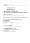
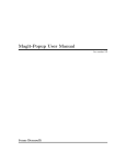
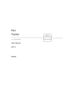
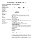
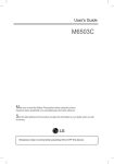
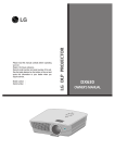
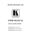
RM-GSM-100 Wireless Analog/Digital Controller User Manual Page | 2 RM-GSM-100 User Manual www.tavacontrol.com [email protected] Table of Contents 1 Introduction .......................................................................................................................................... 3 2 Device Spec ........................................................................................................................................... 3 3 2.1 Electrical Spec ............................................................................................................................... 3 2.2 Mechanical Spec ........................................................................................................................... 3 Installation ............................................................................................................................................ 4 3.1 Mounting....................................................................................................................................... 4 3.2 Wiring ............................................................................................................................................ 5 4 Start-Up Procedure ............................................................................................................................... 6 5 Programming the Module ..................................................................................................................... 7 6 List of Commands.................................................................................................................................. 7 7 6.1 Factory Default IO Names ............................................................................................................. 7 6.2 Commands Summary .................................................................................................................... 8 6.3 Renaming I/Os............................................................................................................................... 8 6.4 Customizing Analog Unit ............................................................................................................. 10 6.5 Adding/Removing Phone ............................................................................................................ 10 6.6 Enabling/Disabling Authentication ............................................................................................. 10 6.7 Power on Mode: ......................................................................................................................... 11 6.8 Requesting I/O Status ................................................................................................................. 11 6.9 Opening/Closing Output Relays .................................................................................................. 11 6.10 Adjusting Analog Output Values ................................................................................................. 11 6.11 Enabling and Disable Alarm ........................................................................................................ 12 6.12 Setting Current Mode ................................................................................................................. 12 6.13 Resetting Parameters.................................................................................................................. 12 Troubleshooting .................................................................................................................................. 13 7.1 System Status LED ....................................................................................................................... 13 7.2 Common Issues ........................................................................................................................... 13 7.2.1 Device not responding to any text message ....................................................................... 13 7.2.2 Analog values are off from actual values ............................................................................ 13 7.2.3 Device is not notifying user on alarm condition ................................................................. 13 Page | 3 RM-GSM-100 User Manual www.tavacontrol.com [email protected] 1 Introduction RM-GSM-100 module is a wireless monitoring and control device capable of receiving and sending messages via SMS (Text Messaging). It can be used to control a variety of equipment such as variable frequency drives (VFDs), actuators, etc. Commands such as turning relays on/off or setting analog output values can be accomplished by sending simple text messages to the module. The module can also respond to the status request by reporting analog and digital I/Os’ conditions. 2 Device Spec 2.1 Electrical Spec Input Power Requirement: 24VAC (150mA) Inputs: o (2) Dry Contact Input o (1) 0-10V Analog Input o (1) 0-20mA or 4-20mA Analog Input Outputs: o (2) SPDT Relay Outputs (10A @ 120VAC) o (1) 0-10V Analog Output (~1% Accuracy) o (1) 0-20mA or 4-20mA Analog Input (~1% Accuracy) 2.2 Mechanical Spec Enclosure Dimensions (L x W x H) (in / mm): o 5.00 x 7.50 x 1.75 in. / 127.00 x 190.50 x 44.45 mm Enclosure Type: o Flame Retardant ABS Terminal Type: o Pluggable o Screw Connection o M3 Screw Thread o Tightening torque (0.5 – 0.6 Nm) Page | 4 RM-GSM-100 User Manual www.tavacontrol.com [email protected] 3 Installation 3.1 Mounting Prior to attaching the front cover to the back cover make sure the SIM card (not provided) is properly installed on the upper right corner of the board (see Figure 1). Make sure the SIM card does NOT require PIN for operation. Otherwise, the module will not work and may cause to lock the SIM permanently. SIM Card Holder Figure 1 SIM Card Holder Location With the four screws provided attach the back cover to the front cover and with the end panel properly aligned. RM-GSM-100 is a wall mountable device. Install the module in a dry environment and away from extreme temperature conditions. The device requires a 24VAC power source capable of providing at least 150mA of continuous current. Analog inputs/outputs should be wired using shielded cables and they need to be routed away from noisy environments (i.e. output wires of a drive). Improper wiring of analog signals can degrade the performance of the device. Page | 5 RM-GSM-100 User Manual www.tavacontrol.com [email protected] In order for proper operation it is critical for the module to be installed in a place where there is sufficient reception from a cell tower. If the device is mounted inside a metal enclosure, the antenna should still be located outside in order for the device to work properly. Figure 2 Basic Mounting Diagram 3.2 Wiring In order to reduce incorrect wiring, each connector is labeled with appropriate input name. There is also a legend on the front cover of the module with appropriate input labels. For optimum performance, make sure wirings going in and out of the module are properly shielded and are away from noisy environment. Also always use a shielded wire for analog input/outputs for better performance. Page | 6 RM-GSM-100 User Manual www.tavacontrol.com [email protected] Figure 3 Terminal Description Shield in the shielded wire should be terminated on one end ONLY to prevent ground loops. Figure 4 Basic Wiring Diagram 4 Start-Up Procedure Prior to applying power to the module, double check the wiring. Incorrect wiring may permanently damage the device and/or cause malfunction. Apply power to the module. The power LED will turn on. Wait for the status led to start blinking. At this point the Cell stat LED should be steadily blinking (0.5s on during 1s period). If the antenna and the SIM Page | 7 RM-GSM-100 User Manual www.tavacontrol.com [email protected] card are properly installed the module will register with the cellular network and the GSM stat LED will start blinking slowly (0.3s on during 3s period). At this point, the device is ready to be programmed and commanded. 5 Programming the Module After initial start-up, a few commands need to be sent to the module in order to properly set it up: Add phone number(s) The module requires having at least one phone number in memory, so that in an event of an alarm condition it can reach the end user. When authentication mode is active, the module also authenticates the user based on the phone # as well as the password. Set desired power-on mode Depending on what the application is, it may be necessary for the module to revert back to its previous known state after a reset or a power failure occurs or for safety reasons, the module may need to be in the off state after a power failure. By default the module will go to the off state if there is a reset or power failure. 6 List of Commands The communication with this device is done via sending text messages. After sending a text message to the module, a response message is send back indicating whether the command was executed successfully or not. It is possible to combine multiple commands into one text message by separating them via commas “,”. Command1, command2, command3, etc... Most command messages are comprised of the following elements: I/O name Command name Value The message parser is case insensitive. In other words, “IN1” and “In1” are treated the same and are equal. 6.1 Factory Default IO Names Dry Contact Input 1 Dry Contact Input 2 Analog Input Voltage Analog Input Current Output Relay 1 Output Relay 2 “IN1” “IN2” “AIV” “AIC” “OUT1” “OUT2” Page | 8 Analog Output Voltage Analog Output Current RM-GSM-100 User Manual www.tavacontrol.com [email protected] “AOV” “AOC” 6.2 Commands Summary Command Syntax [old_name] name [new_name] [io_name] unit [unit_name] [io_name] min [value] [io_name] max [value] current mode [0 or 1] Power on [auto or man] add phone [phone_number] rem phone [phone_number] auth [yes or no] get stat [relay_name] [on or Off] [analog_out_name] [value] [unit] Turn alarm [on or off] reset all Description Changes IO name (See Section 6.3) Gives a custom unit name to analog port (See Section 6.4) Minimum value corresponding to custom unit (See Section 6.4) Maximum value corresponding to custom unit (See Section 6.4 ) Set Analog Current mode 0-20 or 4-20 (See Section 6.12) Specifies the behavior of module upon power cycle (See Section 6.7) Adds a phone number to memory (See Section 6.5) Removes a phone number from memory (See Section 6.5) Enables/disables authentication (See Section 6.5) Request status report from module (See Section 6.8) Turns on or off the output relay (See Section 6.9) Set analog output value (See Section 6.10) Enables/disables alarm messages (See Section 6.11) Resets the module to factory default values (See Section 6.13) 6.3 Renaming I/Os All I/Os have factory default names which can be customizes to better suit the application. To rename an I/O send the following text message to the device: [old-name] name [new-name] For example, if you want to rename Dry Contact Input 1 (which is named “IN1”) to “RUN”, the following text message should be sent: IN1 name RUN The module then responds with the following message: IN1 name RUN (OK) OR IN1 name RUN ([error message]) Page | 9 RM-GSM-100 User Manual www.tavacontrol.com [email protected] Maximum allowed length of a custom name is seven characters Each I/O should have a unique name Names should start with characters and should not contain white space, comma, etc. Page | 10 RM-GSM-100 User Manual www.tavacontrol.com [email protected] 6.4 Customizing Analog Unit By default, status of analog inputs are reported in terms of (V,mA and percentage). Also to command the analog output values the same units can be used. For many applications, it may be better suited to have customized units for the analog I/Os. Below is the syntax for customizing unit: [analog_port_name] unit [unit_name] , [analog_port_name] min [value] , [analog_port_name] Max [value] For example, if analog output voltage corresponds to the speed of the motor in terms of (Hz) (i.e. 0V=0Hz and 10V=60Hz), the unit can be customized by the following command: AOV unit Hz, AOV min 0, AOV max 60 First message of the above example will assign unit “Hz” to analog output voltage, second message will set the minimum value to 0 Hz, and the last message will set the maximum value to 60Hz. Minimum and maximum values are not values for limiting output voltage or output current, they are simply used to properly map the customized unit into a 0-10V ,0-20mA, or 4-20mA values. Custom minimum and maximum values can range between (-655.00 and +655.00). After customizing the unit, the status report will show the converted value as well as the percentage. If the customized unit was done for analog outputs, the output can be adjusted using the customized unit (See Adjusting Analog Output Values) 6.5 Adding/Removing Phone The module can accept up to 3 phone numbers for authentication purposes or for alarm messages. To add a phone, send the following text message to the unit: add phone [phone_number] To remove a phone, send the following text message to the unit: rem phone [phone_number] 6.6 Enabling/Disabling Authentication To provide additional security, the module can respond to only known phone numbers or unknown phone numbers with a correct password. To enable authentication, send the following text message to the unit: auth yes Page | 11 RM-GSM-100 User Manual www.tavacontrol.com [email protected] Once the authentication is enabled, it is required to provide a password for every SMS sent to the device in the following format: [password], [CMD] For example, if password is 12345, to turn out1 on and then to get a status, send the following text message: “123456, out1 on, get stat” To disable authentication, send the following text message to the unit: “auth no” 6.7 Power on Mode: Depending on the application, it may be necessary for the module to revert back to its previous known state after a reset or a power failure occurs or for safety reasons, the module may need to be in the off state after a power cycle. By default the module will go to the off state if there is a reset or power failure. To set the module to go back to its previous known state prior to power failure, send the following text message: “power on auto” To set the module to stay in off state upon a power failure or reset, send the following text message: “power on man” 6.8 Requesting I/O Status To receive the status of all the I/Os, send the following text message to the unit: “get stat” The module then will respond by reporting the status of each input as well as the current state of the outputs. 6.9 Opening/Closing Output Relays To activate a relay, send the following text message to the unit: [relay_name] on To inactivate a relay, send the following text message to the unit: [relay_name] off For example, to turn relay 1 on, assuming relay1 has a custom name of “fwd”, the following command should be sent to the module: “out1 on” OR “fwd on” 6.10 Adjusting Analog Output Values There is one (1) 0-10V analog output and one (1) 0-20mA or 4-20mA. By default analog output voltage can be set by unit V or by percentage value and analog output current can be set by unit mA or by percentage value: Page | 12 RM-GSM-100 User Manual www.tavacontrol.com [email protected] [analog_out_v_name] [value] V OR [analog_out_v_name] [value] % And [analog_out_i_name] [value] mA OR [analog_out_i_name] [value] mA Examples: “AOV 4.5V” “AOV 30%” “AOC 12mA” If the units for analog outputs have been customized, they can be addressed by their customized unit as well. For example if analog output voltage unit is set as Hz, with minimum of 0Hz and maximum of 60Hz (See section 6.4), the output voltage can also be set as shown below: “AOV 30Hz” In this case, the output voltage will be 5V (50%). If AOV output name was customized to “speed”. The following text message could also be used to change the value: “Speed 30Hz” 6.11 Enabling and Disable Alarm RM-GSM-100 is capable of sending alert messages to the end user if there is a change in condition on one of the dry contact inputs. In order to enable the alarm send the following text to the module: “turn alarm on” To disable alarm send the following text message: “turn alarm off” Note that alarm messages are sent to the stored phone numbers in the module. If there are no phone numbers stored in the memory, no message is generated. 6.12 Setting Current Mode Some equipments work based on a 0-20mA signal and some work based on 4-20mA. In order for the module to calculate the percentage it is required to set it up currently. Factory default is set to 4-20mA signal. To change analog current range (for both input and output) to 0-20mA send the following text message: “current mode 0” To change analog current range (for both input and output) to 4-20mA send the following text message: “current mode 1” 6.13 Resetting Parameters The device can be reset to factory default by sending the following command: Page | 13 RM-GSM-100 User Manual www.tavacontrol.com [email protected] “reset all” After sending this command, all custom names, units, min/max values will be deleted from memory. 7 Troubleshooting 7.1 System Status LED System status LED will blink different number of times in a cycle depending on what state the module is in. This will help to trouble shoot the module. Table below describes different states that the module will be in and corresponding system status LED behavior. Device Condition Description Normal Boot Process GSM Error Device is operating properly Device is in the start-up process Error communicating with GSM module SIM Error SIM Card not installed /requires password/ Malfunction Low/No Reception Antenna not installed properly or the signal quality is weak in the area System Status LED (# of blinks per cycle) 1 3 4 5 7 (Constant blinking) 7.2 Common Issues Below are some of the problems that you may encounter with some suggestions on how to fix the issue. 7.2.1 Device not responding to any text message Check the following: Check the status LEDs. If the System Stat LED is blinking more than once per cycle there may be an issue with the following: o Poor reception/ Antenna Issue o SIM card error o GSM communication error Make sure your subscription to your provider is current 7.2.2 Analog values are off from actual values Noise can cause the analog values to be off and/or erratic. Make sure the analog wires are not running next to your power signals and are far from noisy environment. 7.2.3 Device is not notifying user on alarm condition Make sure the alarm is enabled and that you have added at least one phone number to the device.