1
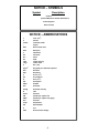
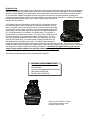
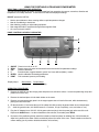
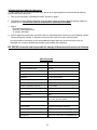
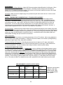
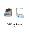
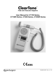
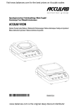
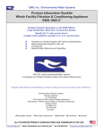
PORTABLE ULTRASOUND
POWER METER
MODEL USP-50
USER MANUAL
BC BIOMEDICAL
USP-50
TABLE OF CONTENTS
Warnings, cautions, notices………………………………………………………….…….…….…....2
Introduction…………………………………………………………………………….…….…….…....6
Optional & Replacement Parts ...............................................................................................….6
Selecting a Location for Operation .........................................................................................….7
Panel Controls and Display Indicator .....................................................................................….7
Operating Procedure ..................................................................................................................7
Short Operating Notes...........................................................................................................…..8
Set Up....................................................................................................................................…..8
Calibration and Program Check ............................................................................................…..8
Serial Computer/Printer Interface ..........................................................................................…..9
USP-50 Parameter Settings Overview ..................................................................................…..9
Programming Print Control…………...………………………………………………..…………….. 9
USP-50 Parameter Settings for USB / RS-232 Interface…………….……………..……………..10
Setting Up HyperTerminal…………………………………………………………..…………………10
Shipping Instructions for the USP-50 ....................................................................................….10
Specifications.........................................................................................................................….11
Maintenance ..........................................................................................................................….12
Water, Temperature Considerations, Transducer Placement...............................................….12
Ultrasound Radiation Levels..................................................................................................….12
Pre-Amendment Acoustic Output Limits………………………………………………..…………...12
Theory of Measuring Ultrasound Power With the Radiation Force Method..........................….13
Warranty…………………………………………………………………………….…………………..14
Sample Inspection Record (2 pages) ..................................................................................….16
USP50_UserManual Rev8
1
WARNING - USERS
The USP-50 Ultrasound Power Meter is for use by
skilled technical personnel only.
WARNING - USE
The USP-50 Ultrasound Power Meter is intended for
testing only and should never be used in diagnostics, treatment or any other capacity where they
would come in contact with a patient.
WARNING - MODIFICATIONS
The USP-50 Ultrasound Power Meter is intended for
use within the published specifications. Any application beyond these specifications or any unauthorized user modifications may result in hazards or improper operation.
WARNING - CONNECTIONS
All connections to patients must be removed before
connecting the Device Under Test (DUT) to the Meter. A serious hazard may occur
if the patient is connected when
testing with the Meter.
Do not connect any leads from the patient directly to
the Meter or DUT.
WARNING - BATTERIES
Turn Power Off and unplug any Battery Eliminator
before replacing batteries or cleaning the surface of
the Meter.
WARNING - LIQUIDS
Do not submerge or spill liquids on the Meter.
Do not operate the Meter if internal components not
intended for use with fluids may have been exposed
to fluid, as the internal leakage may have caused
corrosion and be a potential hazard.
2
CAUTION - SERVICE
The USP-50 Ultrasound Power Meter is intended
to be serviced only by authorized service
personnel. Troubleshooting and service
procedures should only be performed by
qualified technical personnel.
CAUTION - ENVIRONMENT
The USP-50 Ultrasound Power Meter is intended
to function between 15 and 30 °C.
Exposure to temperatures outside this range can
adversely affect the performance of the Meter.
CAUTION - MEDIA
The USP-50 Ultrasound Power Meter is to be
used only with degassed water. Use of any other
media may cause damage a to the meter and
give erroneous results
CAUTION - INSPECTION
The USP-50 Ultrasound Power Meter should be
inspected before each use for wear and
the Meter should be serviced
if any parts are in question.
3
NOTICE – SYMBOLS
Symbol
Description
Caution
(Consult Manual for Further Information)
Center Negative
Direct Current
NOTICE – ABBREVIATIONS
c
centi- (10-2)
C
Celsius
cmH20
centimeter water
°
degree
DUT
Device Under Test
Euro
European
F
Fahrenheit
FS
Full Scale
hrs
Hz
inHg
inH20
k
hours
hertz
inches mercury
inches water
kilo- (103)
kg/cm2
kilograms per centimeter squared
kHz
kilohertz
Kpa
kilopascal
μ
micro- (10-6)
μA
microampere
m
milli- (10-3)-
mA
milliampere
mBar
milliBar
mm
millimeter
mmHg
millimeter mercury
ohm
Press
Pressure
PSI
pounds per square inch
PSIG
pounds per square inch gauge
Sec
seconds
Temp
temperature
US
United States
V
volt
VDC
Direct Current Voltage
4
NOTICE – DISCLAIMER
USER ASSUMES FULL RESPONSIBILITY FOR UNAUTHORIZED
EQUIPMENT MODIFICATIONS OR APPLICATION OF EQUIPMENT
OUTSIDE OF THE PUBLISHED INTENDED USE AND SPECIFICATIONS. SUCH MODIFICATIONS OR APPLICATIONS MAY RESULT
IN EQUIPMENT DAMAGE OR PERSONAL INJURY.
NOTICE – DISCLAIMER
BC GROUP INTERNATIONAL, INC. RESERVES THE RIGHT TO
MAKE CHANGES TO ITS PRODUCTS OR SPECIFICATIONS AT
ANY TIME, WITHOUT NOTICE, IN ORDER TO IMPROVE THE DESIGN OR PERFORMANCE AND TO SUPPLY THE BEST POSSIBLE
PRODUCT. THE INFORMATION IN THIS MANUAL HAS BEEN
CAREFULLY CHECKED AND IS BELIEVED TO BE ACCURATE.
HOWEVER, NO RESPONSIBILITY
IS ASSUMED FOR INACCURACIES.
NOTICE – CONTACT INFORMATION
BC BIOMEDICAL
BC GROUP INTERNATIONAL, INC.
3081 Elm Point Industrial Drive
St. Charles, MO 63301
USA
1-800-242-8428
314-638-3800
www.bcgroupintl.com
[email protected]
Manual USP-50
www.bcgroupintl.com
08/08
Copyright © 2008
Made in the USA
Rev 08
5
INTRODUCTION
The measurement of power output levels of diagnostic and therapeutic ultrasound equipment has become increasingly
important to determine exact patient exposure levels in case a potential risk exists to the patient. Since the Radiation
Control for Health & Safety Act of 1968 and the 1976 Medical Device Amendments to the FDA Act became effective,
all manufacturers of diagnostic Doppler ultrasound equipment are required to submit information regarding their
maximum peak and average exposure level, beam patterns, and other pertinent information. Hospitals are responsible
for regularly scheduled testing (every six months) of output power and safety to
maintain their accreditation.
The Portable Ultrasound Power Meter, Model USP-50, is designed to measure
the ultrasound power output of diagnostic or therapeutic transducers up to 30
watts. The power meter comes complete with all accessories (clamp assembly,
cone assembly, power supply, and tank) in a sturdy foam padded carrying case
(picture right). The water tank requires only one pint of de-gassed distilled water. If de-gassed water is not available, use distilled water. The principle of
measurement is the radiant force method. The meter uses a positioning clamp
to hold the transducer in de-gassed water above a conical target. The ultrasonic energy passes through the water to reflect off the target and is then absorbed by the rubber lining. The radiant power is directly proportional to the
total downward force (weight) on the target. This weight is then transferred
through the target support assembly to the electro-mechanical load cell inside the scale. The cell is in a computercontrolled feedback loop and produces a digital readout in watts of power (custom units) or grams of force. The choice
of units (grams or watts) is selected by front panel pushbutton. The USP-50 is supplied with a plug-in 120 VAC
adapter (using another adapter not rated the same may damage unit). The display resolution is 50 milliwatts.
The following replacement parts can be ordered from BC GROUP :
x
x
x
x
x
OPTIONAL & REPLACEMENT PARTS
Positioning Clamp Assembly
Cone Assembly
120 VAC power adapter # MKD-351500100
USB Cable #YADAP-USB
RS-232 Cable #YADAP-RS
Front view of the USP-50. Shown
is the electronic balance, base
assembly, and test tank.
6
USING THE PORTABLE ULTRASOUND POWER METER
SELECTING A LOCATION FOR OPERATION
The USP-50 should always be used in an environment free from excessive air currents, corrosives, vibration and
temperature or humidity extremes. These factors will affect the displayed readings.
DO NOT operate the USP-50:
x
x
x
x
x
Next to open windows or doors causing drafts or rapid temperature changes
Near air conditioning or heat ducts
Near vibrating, rotating or reciprocating equipment
Near magnetic fields or equipment that generate magnetic fields
On a non level work surface
PANEL CONTROLS & DISPLAY INDICATOR
1
2
3
1.
2.
3.
4.
5.
6.
ON/OFF
ZERO
CAL
F
ENTER
PRINT
4
5
6
Press to turn unit on or off.
Press to zero unit, press as instructed for access and exit from parameter settings.
Used for calibration.
Function button, toggles between “grams” and “user defined (Watts) “ modes.
Used in calibration and setting parameters.
Print command, press to print reading.
Display output
Grams Mode
xxx.xxx g
Custom Mode
xx.xx R(Watts)
OPERATING PROCEDURE
1. Remove the USP-50 from the carrying case and place on a solid level surface. Loosen the positioning clamp and
position it out of the way.
2. Remove the tank and place it in the black holder on the meter.
3. Remove cone target assembly place it in the target support sleeve in back of the tank, while simultaneously
placing the cone in the tank.
4. Fill the test tank to ¼ inch below the top of the rubber liner with recently de-gassed water at room temperature.
(To
obtain de-gassed water, boil distilled water for 15 minutes, fill a jar completely, cover, and allow to cool).
5. Plug the AC Adapter into a 120 VAC, 60 Hz power outlet and plug it into the power jack at the rear of the unit.
Depress the ON/Off button. Let the unit stabilize a few minutes, once stable press ZERO.
6. By means of the positioning clamp, attach the transducer head and place its radiating face 1/8 inch below the
water level, parallel to the water surface, and directly above the center of the cone. Check transducer surface for
uniform wetting (no air pocket or bubbles should be on its surface).
7
7.
With no ultrasonic power applied to the transducer, press the ZERO button to zero the USP-50.
8.
Check response by placing the 1gram test weight on the arm of the cone target ( the flat part that is out of the
water). The USP-50 should read 1.00 grams ± 0.05. Change the units to the watts mode by pressing the “F”
button. The USP-50 should read 14.65 watts ± 0.05 watts. 1 gram is equal to 14.65 watts.
9. Remove the 1 gram weight. Press the ZERO button to zero the unit.
10. Apply power to the Transducer Under Test (TUT). Re-zero before each measurement and take your power reading
when the display has stabilized. It is a good practice to take three readings and average them. If measurement
conditions are not stable, use the grams mode and multiply the readings by 14.65 to obtain watts .
11. Determine the maximum peak power with the maximum duty cycle and pulsed output settings with the equation:
PAVE = Pp ÷ Rtpa
PAVE = calculated average power
Pp = Peak Pulsed Power Setting on unit under test
Rtpa = Ratio of Temporal Peak to Average Power (from each manufacturer)
12. To calculate the watts/cm2 output, take the total watts reading from the unit and divide by the area. The area is
Sd2÷ 4 (d is the diameter of the transducer) if the transducer is smaller than the cone.
Otherwise, use (8.2 cm) the
cone’s diameter as the area.
13. When finished, unplug the USP-50, empty and dry the tank. Dry the cone target assembly. Place the unit, tank,
cone target assembly, and power adapter into the padded case.
SHORT OPERATING NOTES
Line / Power: The USP-50 is supplied with a 120 VAC adapter. Check for correct line voltage before use. For voltages
220/240 VAC, an optional power adapter can be ordered from BC GROUP.
Short Operating Notes Model USP-50
1. Remove all the parts from the carrying case. Move the positioner /
holder upright. Place the tank into the holder. Insert the cone into the tank
and the cone holder into the target support sleeve located in back of the test
tank. Add water (no visible bubbles) to approximately one-quarter inch below the top of the tank.
2. Turn unit on by pressing the ON/OFF button. Zero by pressing “ZERO”.
3. Place the 1 gram weight gently on the cone support arm. A reading of
one gram equals 14.65 watts. Remove the 1 gram test weight.
4. Put the transducer of the equipment under test (EUT) into the positioner /
holder approximately one-eighth inch into the water and centered above the
cone. Zero the scale. Turn on the power to EUT and take readings.
5. Turn off the USP-50 by pressing the ON/OFF button.
SET UP: If you accidentally get into the Parameter Setup menu you can get out by pushing and holding the ZERO
Button until the unit turns off, release the button and the unit will turn back on. The USP-50 Portable Ultrasound Power
Meter is a custom programmed balance with additional hardware (cone target, tank, etc.) designed to provide
ultrasound power readings. If reprogramming to the original parameters does become necessary, the unit must be
returned to BC GROUP’S facility in St. Louis, MO. An hourly labor rate will be charged for any necessary repairs and
recalibration fees will be assessed. A calibration certificate will be returned with the unit.
CALIBRATION and PROGRAMMING CHECK
A 1-gram weight is supplied to check the calibration and programming. With the transducer under test turned off, zero
the unit. Place the weight on the arm of the cone target assembly. Within 3 seconds the unit should read 14.65 watts
(± .05 watts) or 1.0 grams (± .005 grams). If this reading is significantly off, the USP-50 needs to be recalibrated. Send
it to BC GROUP for calibration. It is recommended that the USP-50 be returned to BC GROUP on a yearly
basis for calibration and certification.
8
SERIAL COMPUTER/PRINTER INTERFACE
The USP-50 can be used with an optional USB or RS-232 interface cable for communication with printers and
computers. Installation instructions come with the cable. When the meter is connected directly to a printer, displayed
data can be output at any time by simply pressing PRINT or by using the Auto Print feature. Connecting the meter to a
computer enables you to operate the meter from the computer, as well as receive data. The program used is the
communication program HyperTerminal found on most Window operating systems. The setup of this program is with
the cable instructions.
USP-50 PARAMETERS SETTINGS OVERVIEW
Menu Level 1
1 Weighing
Menu Level 2
1.1 Adapt Filter
Menu Level 3 Default
Menu item
1.1.1
Very stable conditions
1.1.2
2 Stable conditions
1.1.3
Unstable conditions
1.1.4
Very unstable conditions
1.2 Application filter 1.2.1
2 Final readout
1.2.2
Filling
1.3Stability range
1.3.1
1/4 digit
1.3.2
1/2 digit
1.3.3
1 digit
1.3.4
2 2 digits
1.3.5
4 digits
1.5 Function of CAL. 1.5.1
2 CAL adjustment
1.5.1
Linearization, service only
1.5.3
key blocked
1.6 Auto zero
1.6.1
2 On
1.6.2
Off
1.7 Units Toggle
1.7.1 to 1.7.23
*
Set to User def. And grams
5 and 6
Only relevant with optional USB or RS 232 connection
8 Additional Functions 8.1 Block keys
8.2 Auto shut off
9. Reset menu
8.1.1
8.1.2
8.2.1
8.2.2
8.2.3
9.1 Factory settings
2
2
9.1.1
9.1.2
2
* Set to User defined and grams. "F" toggles between the two.
Only On/Off Zero unblocked
All unblocked
After 2 minutes
After 5 minutes
After 10 minutes
Restore
Do not restore
PROGRAMMING PRINT CONTROL
The default print set up is 6.1.2 “Manual with stability”. The unit will send one reading to a computer or printer when
requested, by PRINT key on the unit or by the computer.
To set to Automatic printing:
If the meter is on, turn it off. Turn the unit on, while all the segments of the display are lit, press and hold
“ZERO” (about 2 seconds). Release when the display reads “1.”. This is the set up mode.
Press “F” twice. Display will read “6.1.X”. Press “ENTER” until the desired setting is shown. Either 6.1.3 “Automatic w/o
stability” or 6.1.4 “Automatic at stability”. Press and hold “ENTER” to accept set up”, display will show “6.1.X” with a
small “O” behind it. Press and hold “ZERO” until meter turns off, then release the button. The unit will turn back on.
9
USP-50 PARAMETER SETTINGS FOR THE USB /RS-232 INTERFACE
Menu Level 1
5 Data interface
Menu Level 2
5.1 Baud rate
Menu Level 3 Default
Menu item
5.1.2
300 baud
5.1.3
600 baud
5.1.4
2 1200 baud
5.1.5
2400 baud
5.1.6
4800 baud
5.1.7
9600 baud
5.1.8
19,200 baud
5.2 Parity
5.2.3
5.2.4
5.2.5
2
Odd
Even
None
5.3 Stop bits
5.3.1
5.3.2
2
1 stop bit
2 stop bits
2
Software (Xon-Xoff) USB
Hardware RS-232
None
5.4 Handshake mode 5.4.1
5.4.2
5.4.3
6 Printing
6.1 Manual/Auto print 6.1.1
6.1.2
2
Manual w/o stability
Manual at stability
SETTING UP HYPERTERMINAL
The USP-50 will print to a computer screen using a terminal emulation program. One program HyperTerminal is packed with most
computers and will work for this feature. To set up this program to work with the USP-50 and a computer running
Windows XP see the following:
Left click on START
Highlight ALL PROGRAMS
Highlight ACCESSORIES
Highlight COMMUNICATIONS
Double left click on HYPERTERMINAL or Left click on a setup to open HyperTerminal.
In the HyperTerminal program box Left click on FILE, then Left click on NEW CONNECTION
In the New Connection box, type in a name; Ex: (USP-50). Click on any icon, then Left click OK
In the Connect To box set the connect using line to the correct port. Left click on the down arrow to see your ports
available. Choose one then Left click OK.
In the COM (#) Properties” box (# is the port assigned), under PORT SETTINGS set the following
Data Bits……..1200
Parity………….7
Stop Bits……...1
Flow Control…Hardware
Left click OK .
HyperTerminal is now set up to allow the USP-50 to communicate with a computer and print to the screen.
10
SHIPPING INSTRUCTIONS FOR THE USP-50
To make certain that your Ultrasound Power Meter arrives at our repair department unharmed during shipment,
please follow these instructions:
1. Pack unit as instructed in “Operating Procedure” part #13 on page 5.
2. The package used for shipping should be strong and large enough to allow for adequate packing material on
all sides of unit. DO NOT SHIP THE USP-50 WITHOUT A SHIPPING CONTAINER!
3. Ship to:
BC Group International, Inc.
3081 Elm Point Industrial Drive
St. Charles, MO 63301
8. Enclose paperwork (packing slip, purchase order form, letterhead) which includes your return address, contact
name and telephone number. A description of the work that needs to be done would be helpful.
By using the above instructions you will avoid additional charges which can be incurred if the unit is not
packaged well enough to withstand the possible rough handling during shipment.
BC GROUP cannot be held responsible for damage if these instructions are not followed.
SPECIFICATIONS
Power Range
0 to 30 Watts
Resolution
+50 mW
Minimum Detectable Power
50 mW
Display Sensitivity
0.05 Watt
Accuracy
±3% + One Count
Stabilization
2.5 Second Integration
Maximum Weight Capacity
400 Grams
Maximum Transducer Size
3” Diameter
Transducer Operating Frequency
0.5 to 10 MHz
Test Media
Degassed Water
Computer Interface (Optional)
USB or RS-232
Default Baud Rate
1200
Power Supply
120 VAC to 15 VDC, 100 mA adapter with
6-Ft. Cord. 240 VAC optional.
EMC
Conforms to EN 61326-1, EN 61326-1 Class
B
Electrical Safety
Conforms to EN 60950, EN 61010
Size
5.0” x 10” x 8.5” (H x L x W)
Weight
10 Lbs. Net w / case
Carrying Case
6.0” x 17.0” x 12.0” (H x L x W) padded case
11
MAINTENANCE
Out of Measurement Range Warnings: Model USP-50 accommodates weight differential of ± 400 grams. When
the scale exceeds this range, “oL” error will be displayed. Something may be pressing hard on the target or
support. An “uL” indicates underweight condition. If no obvious error has been made by the user the unit should
be returned for service when any code is displayed.
No Display: Make sure the AC adapter’s plug is fully seated in the jack at the back of the unit. Call our service
department for assistance.
WATER, TEMPERATURE CONSIDERATIONS & TRANSDUCER PLACEMENT
Water as a Measurement Medium: The measurements are to be performed in de-gassed water because
ultrasound propagation in water closely approximates that in tissues (see UL-1-1981, AIUM/NEMA Standard
Publication). The ultrasonic attenuation in water can be taken as a lower limit on the attenuation which will be
encountered in the body. Large areas in the body can consist of low attenuating material such as urine and
amniotic fluid. The use of water prevents measurements in a more highly attenuating material such as liver
equivalent gels from representing the highest possible intensities which might be encountered in the body. A
measurement temperature of 24°C ± 3°C (75°F ± 5°) is chosen for convenience.
De-Gassed Water: Ultrasound power measurement accuracy is affected (lowering the power reading) if the water
contains more than five parts per million of air. To de-gas, boil water for 15 minutes, then pour into a suitable heat
resistant container, seal tightly and place in refrigerator to cool. This process will give the required quality. Before
testing, pour water into tilted test tank to minimize turbulence. An alternative method of de-gassing water is to
heat the water to boiling, then pull a vacuum for five minutes.
Water Temperature:
Water temperature affects accuracy; use a testing temperature of 21 to 27°C ambient. Sonic energy agitates the
water surface through heating and scattering. Testing time should be limited to a few minutes; prolonged testing,
particularly at higher power levels, will produce air bubbles.
Transducer Wetting and Placement: After tilting the transducer into the water at a 45° angle, verify that the
surface is uniformly wetted. The transducer should be positioned above the cone target. Small variations will
occur due to placement. Try various positions above target to obtain a maximum power reading.
ULTRASOUND RADIATION LEVELS
There are no maximum limits in the U.S. for therapy power, only the verification of the displayed setting accuracy
to ± 20% of actual output is required. Exposure levels for physical therapy applicator heads range from 100mW/
cm2 to 3W/cm2. Total power requires multiplication by the radiated cross sectional area in cm2. The power limits
shown in the following table for diagnostic ultrasound have been extracted from FDA Section 510(k) guidance to
manufacturers on submissions and clearance as of February 1993. Refer to the AIUM and FDA publications for
complete and up to date testing standards and interpretations. Measurements are done in all standard modes of
operation. Power intensity is rated as Spatial Peak Temporal Average (ISPTA) and Spatial Peak Pulse Average
(ISPPA). The values in mW/cm2 are derated for tissue and in parenthesis for the water medium (use this chart):
PRE-AMENDMENT ACOUSTIC OUTPUT LIMITS
ISPTA
Tissue
(mW/cm2)
Water
ISPPA
Tissue
(mW/cm2)
Water
Peripheral Vessel
720
1500
190
350
Cardiac
430
730
190
350
Fetal Imaging & Other
*
94
180
190
350
Ophthalmic
17
68
28
110
Use
12
Abdominal, intra-operative,
pediatric, small organ
(breast, thyroid, testes,
etc.), neonatal cephalic,
adult cephalic.
THEORY OF MEASURING ULTRASOUND POWER WITH THE RADIATION FORCE METHOD
Sound is a form of energy that sets the particles in the isonated medium into vibrational motion. The particles
then possess a kinetic energy. If dPm is the rate of the flow of this energy about an area dA, then the mean
acoustic energy is:
Eq. 1
I = dPm/dA
I = Acoustic intensity at a point in that area, Watts/cm2
When a plane sound wave propagates through a uniform non-absorbent medium, the intensity must be the
same for all points in the wave. Let E represent the energy density, i.e., the energy per unit volume. When the
sound energy passes through a unit cross-sectional area with a speed c, the intensity is:
Eq. 2
I = cE
E = Energy density per unit volume, ergs/cm3
c = Ultrasound wave velocity, cm/sec
The radiation pressure effect can be explained by analogy to the application of an alternating electric voltage to
a non-linear load. With the non-linear load it appears that both AC and DC components are present. In
ultrasonics the non-linear element is the density of the fluid and hence acoustic impedance (load) varies in the
same periodical manner as the density. Therefore in ultrasound the two components of pressure, one
alternating and the other direct are present. The average AC pressure per cycle is zero, but the DC pressure of
radiation is:
Eq. 3
PW = I/C
PW = Pressure of Radiation, ergs/cm3
Therefore, from the above two equations, the pressure of radiation (PW) is equal to the energy density (E).
Eq. 4
PW = E
It is this DC pressure of radiation that can be measured. At low frequencies, below 100 KHz, a standard high
frequency hydrophone can be used. For higher frequencies, generally used in medical applications, 1-15 MHz,
hydrophones are not available. At these frequencies the force can be measured using a precision balance and
a radiation force target that is perfectly absorptive. The conversion from force to power can be accomplished
using the equation:
Eq. 5
p = Wgc
W = measured force, grams
g = acceleration, dynes
c = velocity of ultrasound, cm/sec
p = power, ergs/sec
By combining all constants together and converting from ergs/sec to watts, we obtain a simplified equation that
is used to calculate the ultrasonic power once the force is measured:
P = w(14.65)
P = Ultrasonic power in watts
w = Ultrasonic force in grams
To determine the ultrasonic watt density (watts/cm2 or watts/in2) of a given transducer the P is divided by the
cross sectional area of the transducer.
13
WARRANTY
Not withstanding any provision of any agreement the following warranty is exclusive.
BC GROUP warrants each instrument it manufactures to be free from defects in material and workmanship under normal
use and service for the period of 1-year from date of purchase. This warranty extends only to the original purchaser. This
warranty shall not apply to fuses or any product or parts which have been subjected to misuse, neglect, accident, or abnormal conditions of operation.
In the event of failure of a product covered by this warranty, BC GROUP will repair and recalibrate an
instrument returned within 1 year of the original purchase: provided the warrantor's examination discloses to its
satisfaction that the product was defective. The warrantor may, at its option, replace the product in lieu of repair. With
regard to any instrument returned within 1 year of the original purchase, said repairs or replacement will be made without
charge. If the failure has been caused by misuse, neglect, accident, or abnormal conditions of operations, repairs will be
billed at a nominal cost. In such case, an estimate will be submitted before work is started, if requested.
THE FOREGOING WARRANTY IS IN LIEU OF ALL OTHER WARRANTIES, EXPRESSED OR IMPLIED, INCLUDING
BUT NOT LIMITED TO ANY IMPLIED WARRANTY OF MERCHANTABILITY, FITNESS, OR ADEQUACY FOR ANY
PARTICULAR PURPOSE OR USE. BC GROUP SHALL NOT BE LIABLE FOR ANY SPECIAL, INCIDENTAL, OR CONSEQUENTIAL DAMAGES, WHETHER IN CONTRACT, TORT, OR OTHERWISE.
If any failure occurs, the following steps should be taken:
1. Notify BC GROUP giving full details of the difficulty, and include the model, type, and serial numbers (where applicable). On receipt of this information, service data, or shipping instructions will be forwarded to you.
2. On receipt of shipping instructions, forward the instrument, transportation prepaid. Repairs will be made and the
instrument returned, transportation prepaid.
SHIPPING TO MANUFACTURER FOR REPAIR OR ADJUSTMENT
All shipments to BC Group International, Inc. should be made via FedEx or "Best Way" prepaid. The instrument should
be shipped in the original packing carton, or if it is not available, use any suitable container that is rigid and of adequate
size. If a substitute container is used, the instrument should be wrapped in packing material and surrounded with at least
four inches of excelsior or similar shock absorbing material.
CLAIM FOR DAMAGE IN SHIPMENT TO ORIGINAL PURCHASER
The instrument should be thoroughly inspected immediately upon delivery to purchaser. All material in the shipping
container should be checked against the enclosed packing list. The manufacturer will not be responsible for shortages
against the packing sheet unless notified immediately. If the instrument is damaged in any way, a claim should be filed
with the carrier immediately. (To obtain a quotation to repair shipment damage, contact BC Group.) Final claim and negotiations with the carrier must be completed by the customer.
BC GROUP will be pleased to answer all application or use questions, which will enhance your use of this instrument.
Please address your requests or correspondence to: BC Group, 3081 Elm Point Industrial Drive, St. Charles, MO 63301
or call BC GROUP Technical Support at 800-242-8428.
All rights reserved. This manual may not be reproduced in complete form without written permission of BC Group International, Inc. Test forms may be copied as required by the original purchaser of the instrument. Information contained
within this manual is believed to be accurate and reliable. However, BC Group International, Inc. assumes no liability for
its use. BC Group International, Inc. reserves the right to supply its instruments with design changes and/or component
substitutions that may not be documented in this manual.
3081 Elm Point Industrial Drive, St. Charles, MO 63301
Voice: (800) 242-8428 Fax: (314) 638-3200
www.bcgroupintl.com
email: [email protected]
14
NOTE PAGE
15
16
9. CONTINUOUS WAVE MODE CERTIFICATION (Average Power)
WATTS
SELECT
POWER
ON
OFF
DIFF.
WATTS
ALLOWABLE
3.7 - 6.3
5
SAT.
WATTS
SELECT
POWER
ON
OFF
DIFF.
SAT. UNSAT.
WATTS
ALLOWABLE
SAT.
WATTS
SELECT
POWER
ON
OFF
DIFF.
WATTS
UNSAT.
SAT.
WATTS
ALLOWABLE
SAT.
WATTS
SELECT
POWER
ON
OFF
DIFF.
WATTS
Average of 3 Readings
CALCULATIONS
DIFF.
ON
WATTS
OFF
(Pp)
Average of 3 Readings
Pp
RTPA
CALC.
AVERAGE
POWER
(Pp / RTPA)
= Measured Average Power (Av)
Difference
Between
Measured AV
And
Calculated AV
Is Difference < ± 0.6% Of
(Pp / RTPA)
YES NO
11. SHORT TERM LIFE TEST COMPLETE?
YES NO
12. ADDITIONAL TEST (Describe in Detail):
17
ALLOWABLE
SAT.
UNSAT.
10. PULSED MODE CERTIFICATION (Amplitude Modulated Waveform)
POWER
UNSAT.
Average of 3 Readings
Average of 3 Readings
MAX.
PULSE
MODE
ALLOWABLE
14.8 - 25.2
20
Average of 3 Readings
DIFF.
ALLOWABLE
7.4 - 12.6
UNSAT.
11.1 - 18.9
POWER
ON
OFF
WATTS
Average of 3 Readings
15
WATTS
SELECT
DIFF.
10
Average of 3 Readings
WATTS
SELECT
POWER
ON
OFF
REMARKS
UNSAT.