1
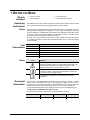
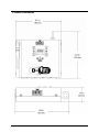
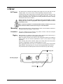
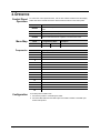
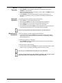
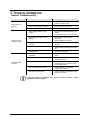
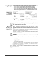
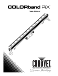
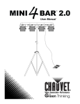
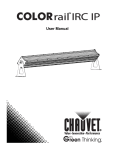
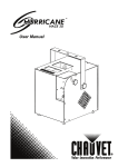
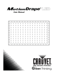
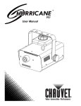
User Manual TABLE OF CONTENTS 1. Before you Begin ................................................................................. 3 What is Included................................................................................................ 3 Unpacking Instructions ...................................................................................... 3 Claims ........................................................................................................................ 3 Text Conventions .............................................................................................. 3 Icons .................................................................................................................. 3 Document Information ....................................................................................... 3 Product at a Glance .......................................................................................... 4 Safety Notes ...................................................................................................... 4 2. Introduction .......................................................................................... 5 Product Overview .............................................................................................. 5 Product Dimensions .......................................................................................... 6 3. Setup ..................................................................................................... 7 AC Power .......................................................................................................... 7 Mounting ........................................................................................................... 7 Orientation ................................................................................................................. 7 Rigging ....................................................................................................................... 7 4. Operation .............................................................................................. 8 Control Panel Operation.................................................................................... 8 Menu Map ......................................................................................................... 8 Frequencies ............................................................................................................... 8 Configuration ..................................................................................................... 8 Manual Operation....................................................................................................... 9 Automatic Operation .................................................................................................. 9 Miscellaneous Operations .......................................................................................... 9 5. Technical Information........................................................................ 10 General Troubleshooting ................................................................................ 10 Contact Procedure .......................................................................................... 11 CHAUVET® Contact Information .................................................................... 11 Returning Products to CHAUVET® ................................................................ 11 DMX Primer ..................................................................................................... 12 Starting Address....................................................................................................... 12 Product Linking (Daisy Chain) .................................................................................. 12 DMX Cabling ............................................................................................................ 13 DMX Connectors ...................................................................................................... 13 6. Technical Specifications ................................................................... 14 Page 2 of 14 D-Fi™ 2.4GHz User Manual (Rev. 04) 1. BEFORE YOU BEGIN What Is Included 1 x D-Fi™ 2.4GHz 1 x Power Supply 1 x Warranty Card 1 x Quick Reference Guide Unpacking Instructions Immediately upon receipt, carefully unpack this product and check the container to make sure you have received all the parts indicated above in good condition. Claims If the container or the material inside the container (this product and any other accessory included) appears damaged from shipping, or shows signs of mishandling, notify the carrier immediately, not CHAUVET®, upon receipt of the damaged merchandise. Failure to do so in a timely manner may invalidate your claim with the carrier. In addition, retain the container and all the packing material for inspection. For other issues such as missing components or parts, damage not related to shipping, or concealed damage, file a claim with CHAUVET® within seven (7) days of receiving the merchandise. Text Conventions Convention 1~512 50/60 Settings Menu > Settings <ENTER> ON Icon Icons Meaning A range of values A set of values of which only one can be chosen A menu option not to be modified A sequence of menu options to be followed A key to be pressed on the product’s control panel A value to be entered or selected Meaning This paragraph contains critical installation, configuration, or operation information. Failure to comply with this information may render the product partially or completely inoperative, cause damage to the product, or cause harm to the user. This paragraph contains important installation or configuration information. Failure to comply with this information may prevent the product from functioning correctly. This paragraph reminds you of useful, although not critical, information. Document Information The information and specifications contained in this document are subject to change without notice. CHAUVET® assumes no responsibility or liability for any errors or omissions that may appear in this manual. CHAUVET® reserves the right to update the existing document or to create a new document to correct any errors or omissions. You can download the latest version of this document from www.chauvetlighting.com. © Copyright 2011 CHAUVET®. All rights reserved Electronically published by CHAUVET® in the United States of America D-Fi™ 2.4GHz User Manual (Rev. 04) Author Date Editor Date A. Diaz 10/13/11 B. Pillow 10/14/11 Page 3 of 14 Product at a Glance Use on Dimmer Outdoor Use Sound Activated DMX Master/Slave Safety Notes Auto Programs Fixed voltage (120 V or 230 V) Replaceable Fuse User Serviceable Duty Cycle Please read the following Safety Notes carefully before working with this product. They include important safety information about its installation, usage, and maintenance. Page 4 of 14 Always connect this product to a grounded circuit to avoid the risk of electrocution. Make sure the power cord is not crimped or damaged. Never disconnect this product from power cord by pulling or tugging on the cord. If mounting this product overhead, always secure it to a fastening device using a safety cable. Make sure there are no flammable materials close to the unit while operating. Always make sure that the voltage of the outlet to which you are connecting this product is within the range stated on the decal or rear panel of the product. This product is for indoor use only! (IP20) To prevent risk of fire or shock, do not expose this product to rain or moisture. Never connect this product to a dimmer. Never carry this product from the power cord or any moving part. The maximum ambient temperature is 104° F (40° C). Do not operate this product at higher temperatures. In the event of a serious operating problem, stop using the unit immediately. Never try to repair this product. Repairs carried out by unskilled people can lead to damage or malfunction. Please contact the nearest authorized technical assistance center. Keep this User Manual for future consultation. If you sell this product to another user, be sure that they also receive this document. D-Fi™ 2.4GHz User Manual (Rev. 04) 2. INTRODUCTION Product Overview Mounting Hole Safety Hook Antenna Top View Bottom View Power In 3 pin DMX In 3 pin DMX Out 5 pin DMX In 5 pin DMX Out D-Fi™ 2.4GHz User Manual (Rev. 04) Page 5 of 14 Product Dimensions Page 6 of 14 D-Fi™ 2.4GHz User Manual (Rev. 04) 3. SETUP AC Power This product has an external fixed voltage power supply and it can work with an input voltage of either 115 V, 60 Hz or 230 V, 50 Hz, depending on the specific model. To determine the power requirements for this product (power outlet and wiring), use the current value listed on the label affixed to the product’s back panel, or refer to the product’s specifications chart. The listed current rating indicates the product’s average current draw under normal conditions. Always connect this product to a protected circuit (circuit breaker or fuse), making sure that it has an appropriate electrical ground to avoid the risk of electrocution or fire. Never connect this product to a rheostat (variable resistor) or dimmer circuit, even if the rheostat or dimmer channel serves only as a 0 to 100% switch. Mounting Before mounting this product, read and follow the safety recommendations indicated in the Safety Notes section (page 2 of this manual). Orientation The D-Fi™ 2.4GHz may be mounted in any position; however, make sure adequate ventilation is provided around the product. Rigging Before deciding on a location for this product, always make sure that it will be easy to access the unit for maintenance and programming purposes. Make sure that the structure onto which you are mounting this product can support its weight. Please see the Technical Specifications section of this manual for weight information. When mounting this product overhead, always use a safety cable. Mount the product securely to a rigging point, whether an elevated platform or a truss. When rigging this product onto a truss, you should use a mounting clamp of appropriate weight capacity. The bracket has a 12 mm hole, which is appropriate for this purpose. The product also has two teardrop holes located on the back for easy wall mounting. Mounting Hole Mounting Diagram Safety Hook D-Fi™ 2.4GHz User Manual (Rev. 04) Page 7 of 14 4. OPERATION Control Panel Operation To access the control panel functions, use the four buttons located around the display. Please refer to the Product Overview to see the buttons location on the control panel. Button <MODE> Press to find an operation mode or to back out of the current menu option <ENTER> Press to activate a menu option or a selected value <UP> <DOWN> Menu Map Frequencies Configuration Page 8 of 14 Function Mode Press to scroll up the list of options or to find a higher value Press to scroll down the list of options or to find a lower value Programming Steps Description Receive Mode r001 001-016 Sets Receive Mode channel Transmit Mode t001 001-016 Sets Transmit Mode channel Channel Frequency (in Ghz) 1 2.433 2 2.4362 3 2.4394 4 2.4426 5 2.4458 6 2.449 7 2.4522 8 2.4554 9 2.4586 10 2.4618 11 2.465 12 2.4682 13 2.4714 14 2.4746 15 2.4778 16 2.481 To set this product in DMX mode: 1. Connect this product to a suitable power outlet. 2. Connect a DMX cable from the DMX output of the DMX controller to the DMX input socket of this product. D-Fi™ 2.4GHz User Manual (Rev. 04) Manual Operation Automatic Operation To operate the product in manual mode, do the following: 1. Press <MODE> to switch between Transmitter (t) or Receiver (r), then press <ENTER> to save the setting. 2. While the Transmitter or Receiver is flashing, press the <UP> or <DOWN> buttons to select your desired frequencies. 3. Press <ENTER> to store the selected frequency before the Transmitter (t) or Receiver (r) stops flashing. The (t) or (r) symbol on the display will flash for 20-40 seconds. To operate the product in automatic mode, do the following: 1. Press <AUTO> to enter Auto Mode on both units. 2. Press and hold <AUTO> on the first unit, which will be the Transmitter (t). 3. Press <AUTO> twice on the second unit, which will be the Receiver (r). 4. Press <ENTER> to store your choice. You are now in “Auto Mode”. 5. In Auto Mode, press and hold <AUTO> on the Transmitter for 8-10 seconds to scan for the clearest channel and to sync your receivers to the Transmitter. Auto scan syncing must be done within a distance of 10 meters (32.81 ft). Miscellaneous Operations To auto scan and sync receivers, follow the below instructions: 1. In Auto Mode, press and hold <AUTO> for 8-10 seconds to scan for the clearest channel and to sync the Receiver(s) to the Transmitter. The LED display will flash, acknowledging the sync. To check which frequency you are using: 1. Press <ENTER> while the Transmitter and Receiver(s) are synced. The frequency will show on the LED display. To clear the receiver, do the following: 1. On the receiver, press and hold <AUTO> for 5 seconds. The stored frequency will be cleared. The (t) or (r) symbol on the display will flash for 20-40 seconds. You can sync an unlimited amount of Receivers to one Transmitter. To ensure strong signals, the units should be elevated 5 feet or higher off the ground and remain in an unobstructed line of sight of each other. D-Fi™ 2.4GHz User Manual (Rev. 04) Page 9 of 14 5. TECHNICAL INFORMATION General Troubleshooting Symptom Product does not power up Possible Cause Possible Action No energy on power outlet Check power outlet Change to another outlet Loose or damaged power adapter Check the power transformer Internal problem Send product for repair Wrong starting address on the product Set the correct starting address on the product Use the right fader(s) on the controller Product does not respond to DMX Intermittent DMX Problems Wrong DMX personality on the product Set the correct DMX product’s personality Assign the faders accordingly Wrong polarity setting on the DMX controller Change the signal polarity on the controller Loose or damaged DMX cable Check the DMX cable before the faulty unit Internal problem Send product for repair Signal cables are not DMX compatible Replace non DMX cables with true DMX cables Interference with AC or radio signals Keep DMX cables away from AC wires or radio equipment DMX cable too long Install an optically coupled DMX amplifier right before the product with intermittent problems Too many products connected Install an optically coupled DMX amplifier after unit #32 Terminator not connected Install a terminator, as indicated in the DMX Primer section. If you still experience problems after trying the above solutions, contact CHAUVET® Technical Support. Page 10 of 14 D-Fi™ 2.4GHz User Manual (Rev. 04) Contact Procedure CHAUVET® Contact Information In case you need to return a product or request support, follow the procedure below: If you live in the US, contact CHAUVET® World Headquarters (see below). If you live in the UK or Ireland, contact CHAUVET® Europe Ltd.(see below). If you live in any other country, DO NOT contact CHAUVET®. Instead, contact your distributor of record. Refer to our Web site for contact details of distributors outside the US, United Kingdom, or Ireland. World Headquarters CHAUVET® General Information Address: 5200 NW 108th Avenue Sunrise, FL 33351 Voice: (954) 929-1115 Fax: (954) 929-5560 Toll free: (800) 762-1084 Technical Support Voice: (954) 929-1115 (Press 4) Fax: (954) 756-8015 Email: [email protected] World Wide Web www.chauvetlighting.com United Kingdom & Ireland CHAUVET® Europe Ltd. General Information Address: Unit 1C Brookhill Road Industrial Estate Pinxton, Nottingham, UK NG16 6NT Voice: +44 (0)1773 511115 Fax: +44 (0)1773 511110 Technical Support Email: [email protected] World Wide Web www.chauvetlighting.co.uk If you live outside the US, United Kingdom, or Ireland, contact your distributor of record and follow their instructions on how to return CHAUVET® products to them. Visit our Web site for contact details. Returning Products to CHAUVET® Call the corresponding CHAUVET® Tech Support office and request a Return Merchandise Authorization (RMA) number before shipping the product. Be prepared to provide the model number, serial number, and a brief description of the cause for the return. You must send the merchandise prepaid, in its original box, and with its original packing and accessories. CHAUVET® will not issue call tags. Clearly label the package with the RMA number. CHAUVET® will refuse any product returned without an RMA number. DO NOT write the RMA number directly on the box. Instead, write it on a properly affixed label. Before sending the product, clearly write the following information on a piece of paper and place it inside the box: Your name Your address Your phone number The RMA number A brief description of the problem Be sure to pack the product properly. Any shipping damage resulting from inadequate packaging will be your responsibility. As a suggestion, proper UPS packing or doubleboxing is always a safe method to use. CHAUVET® reserves the right to use its own discretion to repair or replace returned product(s). D-Fi™ 2.4GHz User Manual (Rev. 04) Page 11 of 14 DMX Primer The USITT DMX512-A data transmission protocol (DMX, from now on) is based on the EIA-485 standard and it has 512 channels (001 to 512). This system requires a controller (DMX controller), one or more DMX compatible products, and a DMX circuit (also known as “DMX universe”) to link the products to the controller. Depending on their complexity and features, DMX compatible products may require from one to more than 30 DMX channels to operate. Some DMX products have multiple operation modes (also known as “personalities”), each with its own number of channels and controllable parameters. Starting Address In the DMX system, the controller sends DMX data to each product based on the product’s starting address. The starting address is the number of the DMX channel (001 to 512) assigned to the product’s first control channel (Channel 1). When assigning starting addresses to multiple products, it is critical to ensure that no starting address is already in use by another product to prevent channels from overlapping. Otherwise, the affected products may operate erratically. For instance, a user has two DMX compatible products. Product “A” has four channels and product “B” has six channels. If the user configures the starting address of product “A” to “001”, channels 001 through 004 on the DMX controller will control product “A”. This means that the user should assign the starting address of product “B” to “005” or higher. For a starting address of “005”, the DMX controller would use channels 005 to 010 to control product “B”. It is possible to control multiple products of the same type by assigning each one of them the same starting address. In this case, all the products would respond in unison (synchronized) to the signals from the DMX controller. Product Linking (Daisy Chain) DMX compatible products receive the control signals from the DMX controller through the DMX cables. Each product has a DMX In and a DMX Out connector. The figure to the right illustrates how the products link to each other using multiple segments of DMX cable in a sequential format called “daisy chain”. The order in which the products connect to the DMX controller is irrelevant because all products receive the same DMX signals and they only respond to them based on their individual starting addresses. However, it is important to notice that the connections between products should always be as short and direct as possible. To ensure the integrity of the DMX signal, follow the recommendations of the EIA-485 standard: DMX Controller 1st DMX Product 2nd DMX Product To other products The maximum recommended cable length is 500 m (1,640 feet). The maximum recommended number of products on the same daisy chain is 32. Connecting more than 32 products on one daisy chain without the use of a DMX optically-isolated splitter may result in deterioration of the digital DMX signal. Page 12 of 14 D-Fi™ 2.4GHz User Manual (Rev. 04) DMX Cabling The DMX protocol requires using special data cables to accommodate for the high speed digital signals it uses. Despite their apparent similarities, data cables are electrically different from standard microphone cables because they can carry high frequency digital signals and have better protection against electromagnetic interference. You can purchase CHAUVET® certified DMX cables directly from a dealer/distributor or make your own DMX cable. If you choose to make your own DMX cable, you must use a data-grade cable such as the Belden 9841, which has the following electrical characteristics: Type: Maximum capacitance between conductors: Maximum capacitance between conductor and shield: Maximum resistance: Nominal impedance: DMX Connectors shielded, 2-conductor twisted pair 30 pF/ft 55 pF/ft 20 ohms/1000 ft 100~140 ohms Each DMX cable must have a male XLR connector on one end and a female XLR connector on the other end. The DMX protocol indicates that the XLR connectors must have five pins. However, most lighting products use the 3-pin XLR connector. The pin assignment of the 3-pin and 5-pin XLR connectors in a DMX cable is as follows: Male Plug Female Plug Signal 3-Pin 5-Pin 5-Pin 3-Pin Signal Common 1 1 1 1 Common Data - 2 2 2 2 Data - 3 Data + Data + 3 3 3 Not used 4 4 Not used Not used 5 5 Not used You can use the above table to create a 3-pin/3-pin cable, a 5-pin/5-pin cable, or a 3pin to 5-pin adapter. The DMX daisy chain uses a terminator to reduce signal transmission problems, especially with long cables. The terminator consists of either a 3-pin or 5-pin XLR male plug with a 120 Ω, ¼ W resistor connected to the wire side of pins 2 and 3, as shown below. The terminator plug connects to the DMX Out socket of the last DMX product in the daisy chain. Do not allow the common wire of the DMX cable to touch the product’s chassis ground. This could cause a ground loop, which may affect your products’ performance. Test all DMX cables with an ohmmeter to verify the correct polarity of the wires, and to make sure that they are not touching the shield or each other. D-Fi™ 2.4GHz User Manual (Rev. 04) Page 13 of 14 6. TECHNICAL SPECIFICATIONS Dimensions and Weight Length Width Height Weight 5.8 in (152 mm) 6.1 in (156 mm) 1.6 in (40 mm) 1 lbs (.5 kg) Note: Dimensions in inches rounded to the nearest decimal digit. Power Wireless Thermal DMX Ordering Page 14 of 14 Power Supply Type Range Input Voltage External 100~240 V, 50/60 Hz 9 V DC 500 ma RF Output Refresh Rate Frequency Range 18.5 dbm max range 230 m 15 Hz/s 2.433 – 2.481 GHz Maximum External Temp. Cooling System 104° F (40° C) Convection I/O Connectors Connector Type 3- and 5-pin XLR Sockets Product Name Item Code Item Number D-Fi™ 2.4GHz 02080308 DFI2.4GHZ D-Fi™ 2.4GHz User Manual (Rev. 04)