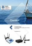
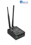
Download 3G Mobile Router (RUT100) User Manual
Transcript
LEGAL NOTICE Copyright © 2012 TELTONIKA Ltd. All rights reserved. Reproduction, transfer, distribution or storage of part or all of the contents in this document in any form without the prior written permission of TELTONIKA Ltd is prohibited. The manufacturer reserves the right to modify the product and manual for the purpose of technical improvement without prior notice. Other product and company names mentioned herein may be trademarks or trade names of their respective owners. CE COMPLIANCE This equipment has been tested and found to comply with the limits for a Class B digital device. CE mark declaration of conformity can be found at Teltonika WEB page www.teltonika.eu ATTENTION Before using the device we strongly recommend read this user manual. Do not rip the device. Do not touch the device if the device block is broken or its connecting wires are without isolation. All wireless devices for data transferring may be susceptible to interference, which could affect performance. The device is not water-resistant. Keep it dry. The device requires high 230V AC voltage. IMPORTANT NOTES! It is mandatory to read the notes and manual carefully before starting to use the device. TECHNICAL SUPPORT CONTACTS If you face any problems related to the device, which you are not able to solve by yourself, you are always welcome to address our technical support department by e-mail [email protected]. We will be very glad to help you. 2|Page Table of Contents 1 2 SAFETY INFORMATION ........................................................................................................................5 PRODUCT OVERVIEW ............................................................................................................................6 2.1 Introduction .............................................................................................................................................6 2.2 Package contents .....................................................................................................................................6 2.3 System requirements ...............................................................................................................................6 2.4 RUT104 Hardware, LED's and connections ......................................................................................7 2.4.1 Back panel......................................................................................................................................7 2.4.2 Front panel ....................................................................................................................................7 3 GETTING STARTED.................................................................................................................................8 3.1 Initial setup ...............................................................................................................................................8 3.2 Router installation guide.........................................................................................................................8 4 ROUTER CONFIGURATION .................................................................................................................9 4.1 Connect to router WEB configuration page using wired connection .............................................9 4.2 Connect to router WEB configuration page using wireless connection ...................................... 10 4.3 WEB configuration page interface structure .................................................................................... 11 4.4 Quick Setup ........................................................................................................................................... 12 4.5 Status ...................................................................................................................................................... 13 4.5.1 System Information ................................................................................................................... 13 4.5.2 Hardware information .............................................................................................................. 14 4.5.3 Routes.......................................................................................................................................... 14 4.5.4 Kernel log ................................................................................................................................... 14 4.6 Configuration ........................................................................................................................................ 15 4.6.1 Mobile Network Settings .......................................................................................................... 15 4.6.2 Network Settings ....................................................................................................................... 16 4.6.3 Wireless Settings ........................................................................................................................ 17 4.6.3.1 Hardware wireless settings .................................................................................................. 17 4.6.3.2 Software wireless settings .................................................................................................... 17 4.6.4 Dynamic DNS Settings............................................................................................................. 18 4.6.5 Services........................................................................................................................................ 19 4.6.5.1 SSH ......................................................................................................................................... 19 4.6.5.2 HTTP ..................................................................................................................................... 19 4.7 VPN ....................................................................................................................................................... 20 4.7.1 OpenVPN (site to site ) ............................................................................................................ 20 4.7.1.1 Server configuration............................................................................................................. 21 4.7.1.2 Client configuration ............................................................................................................. 22 4.7.2 GRE Tunnel ............................................................................................................................... 23 4.7.3 IPsec ............................................................................................................................................ 24 4.7.3.1 Manual IPSec Key exchange .............................................................................................. 24 4.7.3.2 Automatic IPSec Key exchange ......................................................................................... 25 4.8 Admin .................................................................................................................................................... 26 4.8.1 Account ....................................................................................................................................... 26 4.8.2 NTP ............................................................................................................................................. 26 4.8.3 Firmware upgrade ...................................................................................................................... 27 4.9 Firewall................................................................................................................................................... 27 4.9.1 Port forwarding .......................................................................................................................... 30 4.9.2 DMZ............................................................................................................................................ 30 4.10 Tools ................................................................................................................................................. 31 4.10.1 Site Survey .................................................................................................................................. 31 4.10.2 Ping Reboot ................................................................................................................................ 31 4.10.3 Diagnostics ................................................................................................................................. 32 4.11 Reboot and Logout......................................................................................................................... 32 5 TECHNICAL SPECIFICATION ........................................................................................................... 33 3|Page 6 7 8 9 Appendix A Configuring PC wireless security ........................................................................................ 35 Appendix B Changing router IP address ................................................................................................. 37 Appendix D Accessing RUT from the WEB ......................................................................................... 38 Appendix E SIM card public or private IP address ............................................................................... 39 4|Page 1 SAFETY INFORMATION In this document you will be introduced how to use 3G Mobile Router safely. We suggest you to adhere to following recommendations to avoid any damage to person or property. You have to be familiar with the safety requirements before starting to use the device! 3G Mobile Router is used to provide a mobile Internet access using a GSM network. To avoid burning and voltage caused traumas, of the personnel working with device, please follow these safety requirements. Device requires power supply source that satisfies all safety requirements listed in LST EN 60950-1 standard. Each power supply source should not exceed 15VA. The PC and power supply source, to which the device is connected, should satisfy LST EN 60950-1 standard. The device can be used on first (Personal Computer) or second (Notebook) computer safety class. Disconnect device from power supply before mounting to avoid voltage effect! Do not mount or serve device during a thunderbolt. To avoid mechanical damages of the device it is recommended to transport the device packed in damage-proof pack. While using the device, it should be placed so, that its indication LED would be visible as they inform in which working mode the device is and if it has any working problems. Protection against over currents, short circuits and earth faults should be provided as a part of the building installation. Two pole protective device is required to protect from short-circuit and earth false. The power of connected device should satisfy power of release device. To disconnect the device plug off AC/DC power adapter from the wall outlet or power strip. The interstice between contacts should be no less than 3mm. Signal level of the device depends on the environment in which it is working. If the device starts working insufficiently only qualified personnel may repair this product. We recommend to forward it to repair centre or to manufacturers. No exchangeable parts inside of the device. 5|Page 2 PRODUCT OVERVIEW 2.1 Introduction Teltonika 3G Mobile Router provides WAN connectivity to wired and wireless clients using the 3G cellular data network. It allows multiple users to get IEEE 802.11 compliant connection within your wireless broadband network with a single 3G data access account and SIM card. 3G Mobile Router is extremely useful for mobile work teams or emergency crews that need access to the broadband Internet but have no permanent base. The 3G/IEEE 802.11 router might be an easy solution to provide Internet connection for commuter vehicles, such as trains or company buses. Quickly set up a IEEE 802.11 hotspot Internet connection to check email and browse the web or share files. 2.2 Package contents RUT104 3G Mobile Router 2 external Wireless LAN antennas 2 External GSM antennas Power adapter CAT5 LAN cable Leaflet “Quick Start Guide” Note: The manufacturer does not supply the SIM card, which is mandatory for setting up a connection to the GSM network! The SIM card may be purchased from your GSM (mobile) service provider! Note: Using a power supply with a different voltage rating than the one included with the RUT104 will cause damage and void the warranty for this product. Note: If any of the components is missing or damaged, please contact the retailer or reseller from which this product was purchased. 2.3 System requirements A computer with Windows®, Macintosh®, or Linux-based operating systems with a network connection (wired or wireless). A web browser Internet Explorer 6.0, Netscape Navigator™ 6.0, Opera 9.0, Mozilla 5.0 or later versions for configuration. 6|Page 2.4 RUT104 Hardware, LED's and connections 2.4.1 Back panel Figure 1. Router back panel view. 1. 2. 3. 4. Main GSM antenna connection. Wireless LAN antenna connection. Aux GSM antenna connection. Wireless LAN antenna connection. 2.4.2 Front panel Figure 2. Router front panel view. 1. GSM LED. A solid light indicates proper connection of the 3G. 2. Reset button. 3. Ethernet socket. 4. Ethernet LED. A solid light indicates proper connection of the Ethernet. A blinking light indicates data transfer. 5. Power LED. A solid light indicates a proper connection to the power supply. 6. SIM card socket. 7. Power supply adapter socket. 7|Page 3 GETTING STARTED 3.1 Initial setup 3G Mobile Router enables to access network using a wireless connection from virtually anywhere within the operating range of wireless network. Some things should be considered before finding place to set up access point: 1. Make sure the power outlet is nearby as the router requires power supply. 2. Keep the access point as central in work area as possible. 3. The number of walls and ceilings between the router and other network devices should be kept to a minimum as each wall or ceiling probably will reduce adapter’s range from 1-30 meters. Signal strength and speed fall off with distance. 4. Higher is often better. Set up the router on the top shelf of a bookcase rather than the bottom one, if it is possible. The antenna usually works best if oriented to point straight up. 5. Building materials make a difference. A solid metal door or aluminum studs may have a negative effect on range. Try to position access point and computers so that the signal passes through drywall or open doorways. Materials and objects such as glass, steel, metal, walls with insulation, mirrors, file cabinets, bricks, and concrete will degrade wireless signal. 6. Keep router away (at least 1-2 meters) from electrical devices or appliances that generate RF noise. 7. If you are using 2.4GHz cordless phones or other wireless products your wireless connection may degrade dramatically or drop completely. Make sure your 2.4GHz phone base is as far away from your wireless devices as possible. The base transmits a signal even if the phone in not in use. 3.2 Router installation guide 1. Attach Wireless LAN and GSM antennas. Remove the antenna from its plastic wrapper. Screw the antenna in a clockwise direction to the back panel of the unit. Position the antenna upward at its connecting joint. This will ensure optimal reception. 2. Insert the SIM card which was given by your GSM (mobile) service provider. 3. Insert the Ethernet cable into LAN Port if the router will be configured using wired connection. 4. Connect the power adapter to the socket on the front panel of 3G Mobile Router. Then plug the other end of the power adapter into a wall outlet or power strip. Note: SIM card is mandatory for setting up connection to the GSM network. However, the manufacturer of this equipment does not supply the SIM card. The SIM card can be purchased from your GSM (mobile) service provider! For APN, user name and password please contact your GSM (mobile) service provider. The 3G Mobile Router must be powered off while inserting or taking out the SIM card. 8|Page 4 ROUTER CONFIGURATION 4.1 Connect to router WEB configuration page using wired connection Step 1 Connect 3G Mobile Router to your PC using LAN cable. Step 2 Setup Local Area Network adapter on your computer (Go to Start > Settings > Network Connections Right click on Local Network Connection select Properties) Step 3 Setup the Local Area network adapter’s IP address. Choose Internet Protocol (TCP/IP) and click Properties. Setup the Local area network adapter to Obtain an IP address automatically and Obtain DNS server address automatically Note: It is possible to assign manually static IP address within 192.168.0.2 - 192.168.0.254 address range with mask 255.255.255.0, gateway 192.168.0.1 and DNS server 192.168.0.1. Step 4 Open the Web browser and type the IP address of the router (Default : 192.168.0.1) and enter the 3G Mobile Router administrator login details to access the Web management tool: The default administrator login settings are: Login: admin Password: admin01 Note: It is strongly recommended to change the password after the first router configuration. Step 5 After successful administrator log on you will see the main page of the 3G Mobile Router Web configuration interface. The device now is ready for configuration. 9|Page 4.2 Connect to router WEB configuration page using wireless connection Note: the Wireless network function is shipped disabled by default and the configuration for the first time can be made only by using wired connection. Step 1 Setup wireless network adapter on your computer (Go to Start>Settings>Network Connections>Right click on Wireless Network Connection associated with the wireless adapter and select Properties): Step 2 Setup the wireless network adapter’s IP address (choose Internet Protocol (TCP/IP) and click Properties): Setup the wireless network adapter to Obtain an IP address automatically and Obtain DNS server address automatically Note: It is possible to assign manually static IP address within 192.168.0.2 - 192.168.0.254 address range with mask 255.255.255.0, gateway 192.168.0.1 and DNS server 192.168.0.1. Step 3 Enable the wireless network connection. Right click on Wireless Network Connection and chose Enable. Step 4 Choose the wireless network (default: www.teltonika.lt) from the list of available wireless networks. Step 5 Open the Web browser and type the device IP address (default 192.168.0.1) and enter the 3G Mobile Router administrator login details to access the Web management. The default administrator login settings are: Login: admin Password: admin01 Step 6 After successful administrator log on you will see the main page of the 3G Mobile Router Web configuration interface. The device now is ready for configuration. 10 | P a g e 4.3 WEB configuration page interface structure The main Web management menu is displayed after successful login into the system (Figure 3). From this menu all essential configuration pages are accessed. Figure 3. Main Management Menu By default the Quick Setup menu is activated. The web management menu has the following structure: Quick Setup – quick router configuration wizard. Status System Information – displays general information of the device status. Hardware information – displays device hardware information. Routes – displays the rules which are currently active on this system. Kernel log – displays the information about device kernel activity. Configuration Mobile Network Settings Network Settings Wireless Settings Dynamic DNS Settings Services – SSH, HTTPS services management. VPN OpenVPN – Create site to site tunnel or site to multi site tunnels. GRE Tunnel – Create GRE tunnel. IPsec – IPsec client settings. Admin Account – change administrator’s password. NTP – Time and time synchronization settings. Firmware upgrade Firewall General settings – General settings for your network interfaces to control network traffic flow. Traffic Rules – Defines policies traveling between different zones. Port Forwarding Custom Rules – Allow to execute arbitrary iptables commands which are not otherwise covered by the firewall framework. Tools Site Survey – shows information about wireless networks in the local geography. Ping Reboot – set up continuous ping IP address with possibility to automatically reboot router if no echo received. Diagnostics – Network utilities such as “Ping”, “Traceroute” and “Nslookup” to diagnose the network connection. 11 | P a g e 4.4 Quick Setup Use Quick Setup to quickly configure basic 3G Mobile Router settings. The configuration is made in four steps (this is the default page when accessing the administration web management interface). To start quick setup wizard click button QUICK SETUP. Step 1. Change router network settings if needed, if not, then leave as it is. Step 2. Configure mobile network settings. The configuration data should be provided by your ISP (Internet Service Provider). Step 3. Configure wireless network settings. It is recommended to use WPA-PSK with TKIP or AES data encryption. The passphrase for data encryption may be 8-63 characters long and can include symbols (!?*&_) and spaces. This passphrase must be the same as Network key in the PC wireless network security settings. If encryption is chosen do not forget to configure your PC settings (refer to Appendix A). Note: If No Encryption will be chosen it will let anyone within the range and with proper equipment to connect to your network. 12 | P a g e Step 4. After successful configuration please click button and then click the button. The router will reboot and start up with new settings. The process will take several minutes. 4.5 Status 4.5.1 System Information System Information menu displays general devices status. Figure 4. System Information Connection information – displays the GSM network information Local Network Information – displays local network configuration. Wireless Information – displays wireless network information. 13 | P a g e 4.5.2 Hardware information Figure 5. Hardware information Uptime – displays the time since the system was last rebooted. Firmware version – displays current version of the firmware. Average system load – displays the average load of the device processor in the period of the last 1 minute, 5 minutes and 15 minutes (a larger value means a larger average load on the processor: <1.0 – System is idle; =1.0 – Normal load; >1.0 – Processor is busy). LAN MAC address – displays wired LAN MAC address. WLAN MAC address – displays wireless LAN MAC address. Memory – displays total, free, cached and buffered system memory. 4.5.3 Routes Figure 6. Routes information ARP – ARP Table shows map of the IP addresses assigned to the MAC addresses. Active IPv4-Routes – shows the active LAN and WAN routes. 4.5.4 Kernel log The Kernel log displays the information about device kernel activity. Figure 7. Kernel log information 14 | P a g e 4.6 Configuration 4.6.1 Mobile Network Settings To set up the GSM connection SIM card is required. SIM card is not supplied with the router. It may be purchased from internet service provider. The following information to connect to the internet is required: 1. APN. Access Point Name (APN). 2. PIN. SIM card PIN number. 3. Authentication method. The authentication protocol, which is used by your Internet Service Provider [None, CHAP or PAP]. 4. User Name. If GSM operator does not require username, leave it blank. 5. Password. If GSM operator does not require password, leave it blank. 6. Enable manual DNS. If GSM operator does not require manual DNS, leave it disabled. 7. DNS server 1. If GSM operator does not require DNS server 1, leave it blank. 8. DNS server 2. If GSM operator does not require DNS server 2, leave it blank. Warning: It is strongly recommended to use SIM card with PIN disabled. Otherwise, if the entered PIN will be wrong, the SIM card will be locked. Figure 8. Mobile network configuration. APN – Access Point Name (APN) PIN – SIM card pin number. Authentication method – Select authentication type PAP, CHAP or None. User Name – Enter your User Name for your mobile connection. Password – Enter your Password for your mobile connection. Enable Manual DNS – check to enter custom DNS server IP addresses DNS server 1 and DNS server 2 are ISP domain servers. 15 | P a g e 4.6.2 Network Settings This section will allow you to change the local network settings of the router and to configure the DHCP settings Figure 9. Network settings. Router IP address. The IP address of the router. The default IP address is 192.168.0.1. Subnet mask. The Subnet Mask of the router. The default subnet mask is 255.255.255.0. Enable DHCP server. Check the box to enable the DHCP server on your router. Uncheck to disable this function Enabled DHCP server allows configuring IP addresses pool that will be assigned by the router. Figure 10. Network settings. IP address from. Starting IP addresses for the DHCP server’s IP assignment. IP address to. Ending IP addresses for the DHCP server’s IP assignment. Lease time. Determines how long IP addresses are assigned for you. During the lease time, the DHCP server cannot assign that IP address to any other clients. The purpose of a lease is to limit the length of time that a client may use an IP address. A lease prevents unused clients from taking up IP addresses when there are more clients than addresses. Enter the Lease time in seconds. WINS address. If WINS (Windows Internet Naming Service ) server is specified, the router at system startup, will register its name and IP address with the WINS server. WINS server is used for mapping host names to network addresses. This results in fast and efficient host name resolution. Specify WINS server IP address. Domain. Enter the domain name for the Router. Some ISP's require it for identification. Check your ISP to see if your broadband Internet service has been configured with a domain name. In most cases, leaving these fields blank will work. 16 | P a g e 4.6.3 4.6.3.1 Wireless Settings Hardware wireless settings Figure 11. Wireless network settings. Enable radio. Check the box to enable the wireless function. If you do not want to use wireless network, uncheck the box to disable the wireless function. IEEE mode. Specify the wireless network mode [B, G, mixed B/G, G Dynamic Turbo]. Channel. Select the channel for the wireless network. Transmit power. Set the maximum transmitter radiation power. 4.6.3.2 Software wireless settings Figure 12. Wireless network settings. SSID. Specify a unique name for your wireless network. Fragmentation. Specify the fragmentation threshold (in bytes), which determines whether data frames will be fragmented and at what size [256-2346/off/auto]. On the 802.11 wireless LAN, frames exceeding the fragmentation threshold will be fragmented, i.e., split into smaller units suitable for the circuit size. Data frames smaller than the specified fragmentation threshold value are not fragmented. Default: off. RTS. Specify the maximum packet size beyond which the wireless LAN card invokes it’s RTS/CTS mechanism [0-2347/off/auto]. Packets that exceed the specified RTS threshold trigger the RTS/CTS mechanism. The card transmits packets smaller than this threshold without using RTS/CTS. Default: off. Fast Frames. Packet aggregation and timing modifications. Default: off. Packet Bursting. More data frames per given time period. Default: off. Compression. Standards based (Lempel Ziv) real-time hardware compression. Default: off. Quality of service (WMM). Check the box to enable applications such as audio, video and voice to have higher priority than less-sensitive data applications. User isolation. Check the box to isolate the wireless clients from communicating with each other. Hide ESSID. Hides the wireless LAN SSID. Default: off. 17 | P a g e Encryption. Choose the authentication method for wireless network: No Encryption. It will let anyone within range and with the proper equipment to connect onto your network within the router operating range. WEP Open System – choose the 64 bit WEP security with one of four pre-shared keys. WEP Shared Key– choose the 128 bit WEP security with one of four pre-shared keys. WPA-PSK – choose the WPA security with pre-shared key. WPA2-PSK – choose the WPA2 security with pre-shared key. WPA-PSK/WPA2-PSK Mixed mode – choose for the coexistence of WPA and WPA2 clients in. WPA-EAP – choose to enable the certificate based authentication. WPA2-EAP – choose to enable the certificate based authentication. Cipher. Choose the encryption method: Auto. Encryption method is chosen by device. Force CCMP (AES). Encryption by the AES algorithm. Force TKIP. Encryption by the TKIP (Temporal Key Integrity Protocol) algorithm. Note: Setting a lower fragmentation threshold value can help improve connection reliability in noisy environments (where radio interference is present). This mechanism does add overhead and therefore reduces effective throughput. Note: Setting a lower RTS threshold value can improve connection reliability and throughput in crowded wireless LAN environments (where many clients are trying to communicate simultaneously). It adds a certain amount of overhead, but can compensate for this by reducing bandwidth lost due to collisions. 4.6.4 Dynamic DNS Settings Dynamic DNS (DDNS) is a domain name service allowing to link dynamic IP addresses to static hostname. To start using this feature firstly you should register to DDNS service provider. Figure 13. Dynamic DNS Settings. Enable Dynamic DNS – check the box to enable DDNS. User name - enter your user name. The router will use it to automatically login to update your IP address in the DDNS server. Password – enter you login password. Hostname - enter your hostname which was registered in DDSN server. Update period – enter IP address update time in seconds. DynDNS service type – DYNDNS service type. Allowed are all DynDNS service types 18 | P a g e 4.6.5 Services In this section HTTP, SSH services which are important for remote control monitoring and management may be enabled and disabled. 4.6.5.1 SSH Figure 14. SSH service configuration Enable SSH. Check the box to enable SSH service. Port. Set port value of the SSH service. Enable access form WAN. Check the box to enable access via SSH from WAN 4.6.5.2 HTTP Figure 15. HTTP service configuration Enable HTTP access from WAN. Check the box to enable management though HTTP from WAN. HTTP port override. Set port number for the HTTP management from WAN. Enable HTTPS access from WAN. Check the box to enable management though HTTPS from WAN. HTTPS port override. Set port number for the HTTPS management from WAN. 19 | P a g e 4.7 VPN 4.7.1 OpenVPN (site to site ) OpenVPN site to site graphical user interface (GUI) implementation allows connecting two remote networks via point-to-point encrypted tunnel. OpenVPN implementation offers a cost-effective simply configurable alternative to other VPN technologies. The OpenVPN security model is based on SSL, the industry standard for secure communications via the internet. OpenVPN implementation uses OSI layer 2 secure network extension using the SSL/TLS protocol. The typical VPN site to site implementation using OpenVPN is presented in Figure 16. Remote Endpoint IP xxx.xxx.xxx.xxx Internet Server Client Tunnel IP 10.0.0.1 Tunnel IP 10.0.0.2 Network IP 192.168.1.0/24 OpenVPN tunnel Network IP 192.168.0.0/24 LAN2 192.168.1.2 192.168.0.2 Figure 16. Typical site to site OpenVPN tunnel configuration Server configuration Local tunnel IP Remote tunnel IP Remote network IP Remote network subnet mask 10.0.0.1 10.0.0.2 192.168.1.0 255.255.255.0 Client configuration Remote Endpoint IP xxx.xxx.xxx.xxx Local tunnel IP 10.0.0.2 Remote tunnel IP 10.0.0.1 Remote network IP 192.168.0.0 Remote network 255.255.255.0 subnet mask The OpenVPN implementation requires server to have public IP or hostname. Also the remote network subnets must be different as in Fig. 23 192.168.0.0/24 and 192.168.1.0/24. If the subnet will be the same tunnel will not be created or may not function correctly due to routing rules. The server and client have almost the same configuration. The difference in the client configuration is the remote endpoint IP or hostname field. Also the client can set up the keep alive settings. For successful tunnel creation a static key must be generated on one side and the same key must be uploaded on the opposite side. Figure 17. OpenVPN instances Role – Select “Client” or “Server” role for the device. New configuration name – Set the name for OpenVPN configuration. Edit – Press Edit button to edit the OpenVPN configuration. Delete – Press Delete button to delete the OpenVPN configuration. 20 | P a g e 4.7.1.1 Server configuration Figure 18. Server configuration Enable. Check box to enable the OpenVPN. Tun/Tap. Select tunneled or bridged connection. Protocol. Select UDP or TCP protocol. Port. Set the OpenVPN port. Default port 1194. LZO. Check box to enable the LZO compression. Default: disabled. Debug level. Select the connection debugging level. Default: 5. Local tunnel endpoint IP. Specify the IP address of the local VPN tunnel endpoint. Remote tunnel endpoint IP. Specify the IP address of remote VPN tunnel endpoint. Resolve Retry. Connection retry count. Default: infinite. Remote network IP address. Specify the remote network IP address. Remote network netmask. Specify the remote network subnet mask. Static pre-shared key. Static key configurations offer the simplest setup, and are ideal for point-to-point VPNs. The GUI allows to upload the static key. Important! The same key must be uploaded in server and client, e.g. if the key was generated in server, then it must be download by clicking Download , then uploaded in the remote client VPN configuration. 21 | P a g e 4.7.1.2 Client configuration Figure 19. Client configuration Enable. Check box to enable the OpenVPN. Tun/Tap. Select tunneled or bridged connection. Protocol. Select UDP or TCP protocol. Port. Set the OpenVPN port. Default port 1194. LZO. Check box to enable the LZO compression. Default: disabled. Debug level. Select the connection debugging level. Default: 5. Authentication. Choose the authentication type “Static key” or “Tls”. Remote host IP address. Specify the remote device (OpenVPN server) IP address. Resolve Retry. Connection retry count. Default: infinite. Local tunnel endpoint IP. Specify the IP address of the local VPN tunnel endpoint. Remote tunnel endpoint IP. Specify the IP address of remote VPN tunnel endpoint. Remote network IP address. Specify the remote network IP address. Remote network netmask. Specify the remote network subnet mask. Static pre-shared key. Static key configurations offer the simplest setup, and are ideal for point-to-point VPNs. The GUI allows to upload the static key. Important! The same key must be uploaded in server and client, e.g. if the key was generated in server, then it must be download by clicking Download , then uploaded in the remote client VPN configuration. 22 | P a g e 4.7.2 GRE Tunnel GRE (Generic Routing Encapsulation RFC2784) is a solution for tunneling RFC1812 private address-space traffic over an intermediate TCP/IP network such as the Internet. GRE tunneling does not use encryption it simply encapsulates data and sends it over the WAN. WAN IP: A.A.A.A WAN IP: B.B.B.B Internet Tunnel 10.0.0.1/24 Tunnel 10.0.0.2/24 GRE tunnel LAN1 192.168.0.0/24 LAN1 192.168.1.0/24 LAN2 192.168.1.2 192.168.0.2 Figure 20. Typical GRE tunnel application connecting two remote networks In the example network diagram (Fig. 20) two distant networks LAN1 and LAN2 are connected. To create GRE tunnel the user must know the following parameters: 1. Source and destination IP addresses (From Fig. 22 A.A.A.A and B.B.B.B). 2. Tunnel local IP address 3. Distant network IP address and Subnet mask Figure 21. GRE tunnel settings Enable GRE Tunnel. Check the box to enable the GRE Tunnel function. TTL. Specify the fixed time-to-live (TTL) value on tunneled packets [0-255]. The 0 is a special value meaning that packets inherit the TTL value. Enable PMTUD. Check the box to enable the Path Maximum Transmission Unit Discovery (PMTUD) status on this tunnel. Remote tunnel endpoint IP address. Set remote tunnel Endpoint IP address. Remote network IP address. Specify remote LAN IP address. Remote CIDR. Specify remote LAN Subnet CIDR value. MTU. Specify the maximum transmission unit (MTU) of a communications protocol of a layer in bytes. 23 | P a g e 4.7.3 IPsec The IPsec protocol client enables the router to establish a secure connection to an IPsec peer via the Internet. IPsec is supported in two modes - transport and tunnel. Transport mode creates secure point to point channel between two hosts. Tunnel mode can be used to build a secure connection between two remote LANs serving as a VPN solution. IPsec system maintains two databases: Security Policy Database (SPD) which defines whether to apply IPsec to a packet or not and specify which/how IPsec-SA is applied and Security Association Database (SAD), which contain Key of each IPsec-SA. The establishment of the Security Association (IPsec-SA) between two peers is needed for IPsec communication. It can be done by using manual or automated configuration. Note: router starts establishing tunnel when data from router to remote site over tunnel is sent. For automatic tunnel establishment used tunnel keep alive feature. 4.7.3.1 Manual IPSec Key exchange Figure 22. Manual IPSec Key exchange Enable IPSec. Check box to enable IPSec IPSec key exchange mode. Select the Manual or Automatic Key exchange. Enable NAT traversal. Enable this function if client-to-client applications will be used. Peers identifier type. Choose “fqdn” or “user fqdn” accordingly to your IPSec server configuration. Phase 1 and Phase 2 must be configured accordingly to the IPSec server configuration. Remote Network Secure Group – Set the remote network (Secure Policy Database) information. Tunnel keep alive. Allows sending ICMP echo request (ping utility) to the remote tunnel network. This function may be used to automatically start the IPSec tunnel. 24 | P a g e 4.7.3.2 Automatic IPSec Key exchange Figure 23. Authentication header settings Enable IPSec. Check box to enable IPSec IPSec key exchange mode. Select the Manual or Automatic Key exchange. Enable NAT traversal. Enable this function if client-to-client applications will be used. Peers identifier type. Choose “fqdn” or “user fqdn” accordingly to your IPSec server configuration. Mode. Select “Main” or “Aggressive” mode accordingly to your IPSec server configuration. My identifier. Set the device identifier for IPSec tunnel. Preshare key – specify the authentication secret [string]. Secret’s length depends on selected algorithm, eg. 128 bit long secret is 16 characters in length, 128 bits / 8 bits (one character) = 16. Remote VPN Endport – set remote IPSec server IP address. Phase 1 and Phase 2 must be configured accordingly to the IPSec server configuration. Remote Network Secure Group – Set the remote network (Secure Policy Database) information. Tunnel keep alive. Allows sending ICMP echo request (ping utility) to the remote tunnel network. This function may be used to automatically start the IPSec tunnel. Ping IP address – Enter IP address to which ICMP echo requests will be sent. Ping period (seconds) – Set sent ICMP request period in seconds. 25 | P a g e 4.8 Admin utilities: Use the Admin menu to define access settings to the device, or to use the following system Account – change administrator’s password. NTP – Manage system time and date. Firmware upgrade – new firmware upgrade. 4.8.1 Account The Administrative Account menu is used for changing the existing administrators’ password. Figure 24. Change administrator password Enter password – enter the new administrator password. Verify password – re-enter the new password to verify its accuracy. Note: The only way to gain access to the web management if you forget the administrator password is to reset the device factory default settings. Default administrator login settings are: User Name: admin Password: admin01 4.8.2 NTP Use this section to manage the system time and date on the device automatically, using the Network Time. Figure 25. Time setting using NTP Current system time. Show the current time set on device. Update interval. Time update interval in seconds. Count of time measurements. Number of time measurements to perform before exiting. 0 means to never stop. 26 | P a g e Offset frequency. Frequency adjustment for the local clock. Delete – click to remove selected NTP servers from the device system. Add – click Add button to add time server. The new field with server will appear. 4.8.3 Firmware upgrade To update your device firmware use the Firmware upgrade section, select the firmware file and click the Firmware upgrade button: Figure 26. Firmware update Choose File – Click the button to select new firmware image from a folder on the PC. Firmware upgrade – Upload the new firmware. 4.9 Firewall This section allows configuring firewall for enhanced router security. Figure 27. Firewall settings. External IP Address. Specify IP address of the external network. IP address can be single address, e.g. 192.168.2.1 or can be used with network mask to specify whole IP ranges - eg. 192.168.2.0/24. Leave empty for any IP address. Internal IP Address. Specify IP address of the local network. Leave empty for any IP address. Direction. Select whether the rule will apply to Inbound or Outbound connections. Port Range. Set port value or range of TCP or UDP protocol. Leave empty to include all ports. Protocol Type. Select TCP, UDP, ICMP or ALL. Action. Select whether specified connections should be allowed or blocked. 27 | P a g e Description. Describe the rule for your convenience. Note: After pressing Save button wait for confirmation before executing next command. Example 1: Block all incoming connection requests Example 2: Allow incoming telnet (port 23) requests from host 84.12.145.17 to IP address 192.168.0.10. This will also create port forwarding rule to make incoming requests to local network possible. Example 3: Block outgoing traffic from IP address 192.168.0.11 on UDP ports (1000 to 2000) to any external host. 28 | P a g e 29 | P a g e 4.9.1 Port forwarding This section will let to manage port forwarding. Figure 28. Port forwarding settings. Application name. Set the name of the application. Input port range. Set incoming port value or range. Protocol. Select TCP, UDP, or BOTH Destination IP address Enter the IP address of the computer on your local network that you want to allow the incoming service to be forwarded. Destination port range. Set destination port value or range Example 1: Forward TCP port 40000 to IP address 192.168.0.100 Example 2: Forward UDP port 40000 to IP address 192.168.0.100 port 50000. Example 3: Forward TCP and UDP ports range 4000-7000 to IP address 192.168.0.100 port 5000. Figure 29. Port Forwarding examples 4.9.2 DMZ A DMZ host is not protected by the firewall and may be vulnerable to attack. You should only use this feature when a special application’s function fails to make an application work. Designating a DMZ host may also put other computers in the local network at risk. When designating a DMZ host, you must consider the security implications and protect it if necessary. 30 | P a g e Figure 30. DMZ settings Enable - Click to enable or disable the DMZ. Destination IP address - Type a host IP address for the DMZ. All remaining incoming packets will be sent to this IP address. 4.10 Tools 4.10.1 Site Survey The Site Survey test shows overview information for wireless networks in a local geographic area. Using this test, an administrator can scan for working access points, check their operating channels, encryption and see signal/noise levels. An administrator can use this feature to identify a clear channel to set the device. Note: Note that Site Survey function can take several minutes to perform. A Site Survey test is performed every time on the startup of the device, therefore the results of the last performed Site Survey test and its time can be found on the page. Thus, to obtain the results, the initiation of the scan is not necessary. To perform the Site Survey test currently, click the Scan button: Figure 31. Site Survey Table Note: The Site Survey function is impossible if the selected wireless interface is disabled. 4.10.2 Ping Reboot The Ping Reboot feature allows rebooting the router if the connection to GSM network is lost. This feature checks (using ICMP echo request, like ping utility) if specific hosts are accessible on the network. Function allows adding several host IP addresses. When at least one server does not respond the router is rebooted if the check box “Enable reboot if no echo received”. Figure 32. Site Survey Table Enable – check the box to enable Ping Reboot feature. 31 | P a g e Ping interval – specify the monitoring time period in seconds Time scale – set ping interval time scale in minutes or hours Retry count – specify the number of failed reach ability checks Enable reboot if no echo received– enable reboot the router if no echo to sent ICMP requests is received. Server to ping – Set the host IP address to which ICMP requests will be sent. 4.10.3 Diagnostics Network utilities such as “Ping”, “Traceroute” and “Nslookup” to diagnose the network connection. Figure 33. Diagnostic tools 4.11 Reboot and Logout Use the Reboot button to reboot the device or press Logout button to log off from device configuration menu: 32 | P a g e 5 TECHNICAL SPECIFICATION Wireless IEEE 802.11 network Standards IEEE 802.11b: 11Mbps, 5.5Mbps, 2Mbps, 1Mbps IEEE 802.11g: 54Mbps, 48Mbps, 36Mbps, 24Mbps, 18Mbps, 12Mbps, 9Mbps, 6Mbps, automatically fall back to 5.5Mbps, 2Mbps, 1Mbps Transmitter output power at antenna connector IEEE 802.11b: 1-11Mbps 20dBm IEEE 802.11g: 6-24Mbps 20dBm 36Mbps 19dBm 48Mbps 17dBm 54Mbps 16dBm Receiver sensitivity at antenna connector IEEE 802.11b: -92 dBm @ 1Mbps -87 dBm @ 11Mbps IEEE 802.11g: -90 dBm @ 6Mbps -70 dBm @ 54Mbps Security WPA/WPA2, WEP 64/128 bit Wireless Frequency Range 2.412GHz to 2.484GHz External Antenna Type Detachable reverse SMA Management User-friendly Web GUI Wired and wireless network status Site survey test Traffic monitoring Firmware upgradeable SSH VPN IPsec pass through, GRE Tunnel pass through GRE tunnel, IPsec client RUT104 Quad Band (850/900/1900/2100 MHz) 33 | P a g e GSM/EDGE/GPRS/HSUPA/HSDPA/UMTS RUT104 Power Class: Power Class 4 (2 W, 33 dBm) for GSM/GPRS 850/900 MHz bands Power Class 1 (1 W, 30 dBm) for GSM/GPRS 1800/1900 Mhz bands Power Class E2 (0.5 W, 27 dBm) for EDGE 850/900 MHz bands Power Class E2 (0.4 W, 26 dBm) for EDGE 1800/1900 MHz bands Power Class 3 (0.25 W, 24 dBm) for UMTS 850/900/1900/2100 MHz bands Power Class 3 (0.25 W, 24 dBm) for 1xRTT & EVDO Electrical characteristics Nominal power supply voltage 9V 12V 21V Current Consumption when idle 600mA 350mA 300mA Current Consumption when operating 980mA 520mA 400mA Temperature & Humidity Operation 0˚ to 55˚ C Humidity 5% to 95% (non-condensing) Transit/Storage -40˚ to 85˚ C LEDS Power Mobile Network Activity LAN Activity Host Operating System Microsoft Windows® 98SE/ME/NT4.0/2000/XP/Vista/7/8, Unix, Linux and MacOS RUT104 Dimensions L = 100mm W = 85mm H = 36mm RUT104 Weight 230g 34 | P a g e 6 Appendix A Configuring PC wireless security 1. Click Start => Settings => Control Panel (The Control Panel should be in Classic view). Double click on the Network Connections icon. 2. Right click on the Local Area Connection for wired or Wireless Network Connection for wireless connection and select Properties. 3. In the tab General Scroll down to Internet Protocol (TCP/IP) and press Properties. 4. Select Obtain IP address automatically and Obtain DNS server address automatically if they are not selected. 5. Click OK to close Internet Protocol (TCP/IP) properties. 6. Choose Wireless Networks tab. Make sure that box Use Windows to configure my wireless network settings is checked and Click View Wireless Networks 35 | P a g e 7. Click Refresh network list 8. Choose the network with SSID witch was configured on the router (default www.teletonika.lt) and click connect. The window asking for the key should appear. The Network key is the passphrase which was typed in the router settings. 36 | P a g e 7 Appendix B Changing router IP address Step 1 Connect to router WEB configuration page. Then go CONFIGURATION then Maintenance. Step 2 Change router IP address: In the field Router IP address write new router address. (eg. 192.168.123.1) Step 2 Change router DHCP server assigned IP address range: Type the fields IP address from and IP address to type new range Example: Router IP address: 192.168.123.1 IP address from: 192.168.123.2 IP address to: 192.168.123.254 Step 3 Reboot the router. 37 | P a g e 8 Appendix D Accessing RUT from the WEB There are two ways to connect the router from internet: 1. Using SIM card with public static IP address 2. Using SIM card with public dynamic IP address witch will be linked to static hostname using DDNS service. Note: If the SIM card is with private IP address then reaching camera from the internet is not possible as connection is routed through a NAT firewall in your provider’s network. SIM card with public static IP address Open your WEB browser and type SIM card IP address, when the camera GSM connection has been set up. After successful connection router’s login page must appear. SIM card with public dynamic IP address For the SIM card with dynamic public IP address the IP address is given for a limited period of time, which is usually no more than a few hours, then the IP address is changed. As he IP address is continuously changed it becomes a problem to connect to the camera. To solve this problem Dynamic Domain Name Service (DDNS) may be used. DDNS is a domain name service allowing to link dynamic IP addresses to static hostname. To start using this feature firstly a hostname must be registered on the DDNS server. After creating account you will get: Hostname Username and Password. To link router’s IP address to the static hostname, Dynamic DNS settings must be configured. To configure DDNS connect to the router WEB configuration page, go the Configuration => Dynamic DNS Settings (Refer to Figure below). Check the Enable check box. Enter username, password and hostname which where got from the DDNS server provider. In the Update period field enter the IP address update interval. Enter the DDNS service provider. After setting DDNS settings press Save button, then press reboot to start router with new settings. 38 | P a g e 9 Appendix E SIM card public or private IP address Step 1 Connect PC to router and check if it is possible to browse Internet. If you are not able then there is problem with MOBILE NETWORK SETTINGS. If you are able then go to next step. Step 2 Type www.whatismyip.com in the web browser and write down the red marked IP address. Step 3 Connect to router web configuration tool and then go STATUS – System Information and write down the marked IP address. Step 4 Compare the IP addresses in step 2 and 3. If they are the same then SIM card is with public IP address, if they are different SIM card is with private IP address. 39 | P a g e


