1
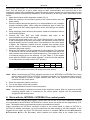
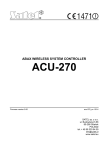
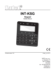
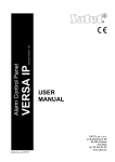
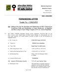
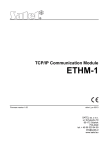
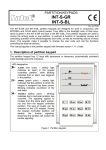
® INT-RX-S 433 MHz KEYFOBS RECEIVER EXPANSION MODULE int-rx-s_en 09/12 The INT-RX-S expansion module works with the INTEGRA (firmware version 1.05 or newer), INTEGRA Plus and VERSA control panels. It enables operation of the alarm system using the 433 MHz keyfobs. 1. Features Superheterodyne radio receiver. Support for up to 248 433 MHz keyfobs (the number of supported keyfobs depends on the control panel). Transmissions from keyfobs secured by the KeeLoq code hopping. Capability to run up to 6 functions with the keyfob. Expansion module firmware update capability. Tamper protection in 2 ways – cover removal and tearing enclosure from the wall. 2. Electronics board terminals: +12V - power input; COM - common ground; CLK - clock; DAT - data. RS-232 port (TTL standard) for updating the expansion module firmware. The expansion module can be connected to the computer using the cables included in the DB9FC/RJ-KPL set, offered by SATEL. tamper switch. LED indicator of communication with the control panel: blinking – data exchange with the control panel; steady light – no communication with the control panel. DIP switch package for setting an individual address of the module. high-sensitivity superheterodyne receiver, immune to spurious signals. antenna. 3. Installation Disconnect power before making any electrical connections. The expansion module should be installed indoors, in spaces with normal air humidity. When selecting the installation place, remember that the thick walls, metal partitions, etc. will reduce the 2 INT-RX-S SATEL range of the radio signal. It is recommended that the expansion module be mounted high above floor. This will allow you to get a better range of radio communication and avoid the risk of expansion module being accidentally covered by people moving around the premises. Mounting expansion module near electrical installations is not advisable, as this may cause malfunction of device. 1. Open the enclosure of the expansion module (Fig. 2). 2. Make the opening in the enclosure base for the communication bus and power cables. 3. Pass the cables through the opening. It is recommended to use a straightthrough unshielded cable. When using the twisted-pair type of cable, the CLK (clock) and DAT (data) signals must not be sent through one twisted pair. 4. Using wall plugs (screw anchors) and screws, fasten the enclosure base to the mounting surface. 5. Connect the CLK, DAT and COM terminals with wires to the communication bus of the control panel. 6. Connect the power leads to the +12 V and COM terminals. If the distance to the control panel is less than 300 meters, the expansion module can be supplied directly from the control panel. If the distance to the control panel is higher, the expansion module must be supplied from another power source, which is located at a closer distance (a power supply unit or an expander with power supply). 7. Using the DIP-switches, set the expansion module address. The switches 1-5 should be used to set the address. It must be different from that of the other modules connected to the communication bus. The address is a sum of numerical values set on the switches 1-5 (see Table 1). If the module works with the VERSA control panel, address 7 must be set (the switches 1-3 in ON position, the other ones in OFF position). the the the the 1 2 3 4 5 DIP-switch number Numerical value 1 2 4 8 16 Table 1. Numerical values corresponding to the switches set to ON position (in the OFF position, the value 0 is assigned to each switch). Note: When connecting the INT-RX-S expansion module to the INTEGRA or INTEGRA Plus control panel to which an INT-RX or INT-RX-S is already connected, it is recommended that you set in the new expansion module a higher address than that in the expansion module already connected to the control panel. 8. Close the expansion module enclosure. 9. Turn on the power of the alarm system. 10. Start the identification function in the control panel. Note: The data relating to keyfobs are stored in the expansion module. After an expansion module containing keyfob data is connected to the control panel, keyfobs will be automatically assigned to the existing users. 4. Work with the INTEGRA / INTEGRA Plus control panels The user can have one 433 MHz keyfob. If more than one INT-RX or INT-RX-S expansion modules are connected to the INTEGRA / INTEGRA Plus control panel, the keyfob will be supported by all of them. The keyfob data are automatically saved to all expansion modules. When connecting the INT-RX-S expansion module to the control panel to which an INT-RX or INT-RX-S is already connected, you must synchronize the data relating to 433 MHz keyfobs. In the keypad service mode, the COPY RX KEYFOBS function is available (STRUCTURE HARDWARE EXPANDERS COPY RX KEYFOBS), which enables the keyfob data to be copied from one SATEL INT-RX-S 3 expansion module to another. In the DLOADX program, if you press the "Write" button in the "Keyfobs INT-RX" window immediately after reading the keyfob data (no changes being made), these data will be saved to all expansion modules. The functions are executed by means of controlling the status of system zones. Using the keyfob, you can control up to 6 zones in the alarm system. These zones should not exist physically and the wiring type programmed in them must be different from NO DETECTOR and FOLLOW OUTPUT. You can program any function for these zones. Pressing the keyfob button (or two buttons simultaneously) will violate the zone and cause suitable reaction from the control panel. For information on adding / removing keyfobs by means of the keypad please refer to the control panel user manual. In the DLOADX program, you can add and remove keyfobs in the "Keyfobs INT-RX" window. The window opening command is available in the "Users" menu. Before making any changes, click on the "Read" button and after you make changes, click on the "Write" button (the keyfob specific data are not read and written by clicking on the button in the DLOADX main menu). Notes: Removal of a keyfob will not erase its settings (dependences between the buttons and zones). When added to the user, the new keyfob will have the same settings as the deleted one. You can delete all keyfobs, including their settings, using the REM. RX KEY FOBS function, available in the keypad service mode (STRUCTURE HARDWARE EXPANDERS REM. RX KEY FOBS). 4.1 Adding a 433 MHz keyfob by means of the DLOADX program Entering the serial number manually 1. Click on the field in the "S/N" column next to the name of the user to whom you want to assign a keyfob. 2. Enter the keyfob serial number and confirm by pressing ENTER. Reading the serial number during transmission 1. Click on the field in the "S/N" column next to the name of the user to whom you want to assign a keyfob. 2. Click on the "New" button. The "New" window will open. 3. According to the command which will appear in the window, press the keyfob button. 4. When the keyfob serial number is displayed in the window, click on the "OK" button. The "New" window will close. The serial number of the new keyfob will be shown in the "S/N" column. Assigning new function to the keyfob button (combination of buttons) 1. Click on the field corresponding to the button (combination of buttons) to which you want to assign a zone. 2. Enter the zone number and press ENTER to confirm. 4.2 Removing a 433 MHz keyfob by means of the DLOADX program 1. Click on the field in "S/N" column next to the name of user whose keyfob is to be removed. 2. Click on the "Delete" button. 3. In the window which will be displayed, click on the “Yes” button to confirm that you want to remove the keyfob. The keyfob serial number shown in the "S/N" column will be erased. 5. Work with the VERSA control panels See the VERSA control panel manuals for information on the functions that can be run with the keyfobs. After adding a keyfob, the functions provided for by the user schedule will be automatically assigned to the buttons. The assigned functions may be replaced with other ones. 4 INT-RX-S SATEL The user manual for VERSA control panels describes the procedures for adding and editing the user by means of the keypad, during which you can add or remove the keyfob and determine what functions will be available from the keyfob. Adding a keyfob is possible in the "Versa – Structure" window, "Hardware" tab, after clicking on the INT-RX in the list of devices. Before making any changes, click on the "Read" button and after you make changes, click on the "Write" button (the data relating to the keyfobs are not read upon clicking on the button or saved upon clicking on the button in the DLOADX program main menu). Notes: Removal of a keyfob by means of the keypad will not erase its settings (the functions assigned to the buttons). When added to the user, the new keyfob will have the same settings as the deleted one. You can delete all keyfobs, including their settings, using the REM.RX K-FOBS function, available in the keypad service mode (2. HARDWARE 1. KPDS. & EXPS. 9. REM.RX K-FOBS). Adding and removing a keyfob with the DLOADX program is carried out in the same way as for the INTEGRA and INTEGRA Plus control panels. Functions can be assigned to the buttons (combination of buttons) in the following way: 1. Click on the field corresponding to the button (combination of buttons) to which you want to assign a new function. 2. Right click on your mouse. A drop-down menu will appear in which you are to select the new function. 6. Specifications Supply voltage ..................................................................................................................12 V DC ±15% Standby current consumption........................................................................................................ 24 mA Maximum current consumption ..................................................................................................... 29 mA Operating frequency band for keyfobs .................................................................. 433.05 ÷ 434.79 MHz Number of supported keyfobs ............................................................................................................248 Supported keyfobs............................................................................... MPT-300, P-2, P-4, T-1, T-2, T-4 Environmental class according to EN50130-5........................................................................................II Operating temperature range .......................................................................................... -10 °C...+55 °C Maximum humidity........................................................................................................................ 93±3% Enclosure dimensions ................................................................................................. 24 x 110 x 27 mm Weight ...............................................................................................................................................30 g The declaration of conformity may be consulted at www.satel.eu/ce SATEL sp. z o.o. ul. Schuberta 79 80-172 Gdańsk POLAND tel. + 48 58 320 94 00 [email protected] www.satel.eu