1
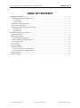
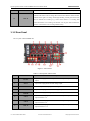
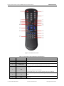
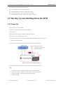
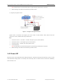
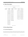
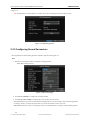
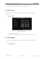
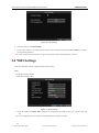
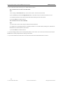
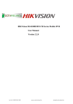
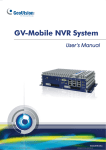
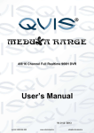
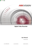
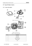
DS-8100HMFI-TH Series Mobile DVR Quick Operation Guide Version 2.2.0 Lo-Call 1890 866 900 www.cctvireland.ie [email protected] Quick Operation Guide of DS-8100HMFI-TH Series Mobile DVR i Thank you for purchasing our product. This manual applies to DS-8100HMFI-TH series Mobile DVR, please read it carefully for the better use of the device. This manual may contain several technical incorrect places or printing errors, and the content is subject to change without notice. The updates will be added to the new version of this manual. We will readily improve or update the products or procedures described in the manual. Lo-Call 1890 866 900 www.cctvireland.ie [email protected] Quick Operation Guide of DS-8100HMFI-TH Series Mobile DVR ii TABLE OF CONTENTS CHAPTER 1 Introduction ............................................................................................................................... 1 1.1 Introduction of Panels and Indicators ..................................................................................................... 2 1.1.1 Front Panel ..................................................................................................................................... 2 1.1.2 Rear Panel ...................................................................................................................................... 3 1.2 IR Remote Control Operations ............................................................................................................... 4 1.3 Power line Description ........................................................................................................................... 6 1.4 Starting Up and Shutting Down the DVR .............................................................................................. 7 1.4.1 Power On ........................................................................................................................................ 7 1.4.2 Power Off ....................................................................................................................................... 8 CHAPTER 2 Basic Operation Guide .............................................................................................................. 9 2.1 Menu Description ................................................................................................................................. 10 2.2 Recording Settings................................................................................................................................ 10 2.2.1 Hard Disk Management................................................................................................................ 10 2.2.2 Configuring Record Parameters ................................................................................................... 11 2.2.3 Video Search................................................................................................................................. 12 2.3 3G Settings ........................................................................................................................................... 12 2.4 WiFi Settings ........................................................................................................................................ 13 2.5 Platform Settings .................................................................................................................................. 14 2.5.1 Accessing by the WVS Platform .................................................................................................. 14 2.5.2 Accessing by the iVMS Platform ................................................................................................. 14 2.6 GPS Settings ......................................................................................................................................... 15 2.7 IPC Settings .......................................................................................................................................... 16 Lo-Call 1890 866 900 www.cctvireland.ie [email protected] Quick Operation Guide of DS-8100HMFI-TH Series Mobile DVR 1 CHAPTER 1 Introduction Lo-Call 1890 866 900 www.cctvireland.ie [email protected] 2 Quick Operation Guide of DS-8100HMFI-TH Series Mobile DVR 1.1 Introduction of Panels and Indicators 1.1.1 Front Panel The front panel of DS-8100HMFI-TH is shown in figure below. Figure 1. 1 Front Panel Note: After opening the panel lock, you can see the USB and eSATA interface, SD/SDHC card interface (reserved) and network interface. Table 1. 1 Description of Interfaces and LED Indicators on the Front Panel No. Name 1 AV OUT 2 USB & eSATA 3 SD/SIM 4 LAN 5 IR Control receiver Receiver for IR remote. 6 POWER indicator Red means the device is standby, green means the DVR starts up normally. 7 READY indicator 8 HDD indicator 9 MODEM indicator 10 ALARM indicator 11 GPS indicator Lo-Call 1890 866 900 Description Video and audio output and voltage output and wire controller composite interface. USB and eSATA composite interface. SD/SDHC card interface (reserved); SIM card interface. Network interface. Green means the device is in normal working status and can be controlled by remote control. Blinking red when data is being read from or written to HDD. Turning off when there is no 3G signal or dialing is disabled. Green means there is 3G signal available. Red means there are alarms. Turning off when there is no GPS module available. Green means there is 3G www.cctvireland.ie [email protected] 3 Quick Operation Guide of DS-8100HMFI-TH Series Mobile DVR module available and blinking green means GPS positioning successfully. One indicator shows the status of two channels. Green means the channel number marked in the left is in the recording status and red means that the channel number 12 marked on the right is recording, and the light blinking red and green means both CH1~16 the two channels are recording. E.g.: Green means channel 1 is recording; Red means the channel 9 is recording; The mixture color of green and red means the channel 1 and channel 9 are recording simultaneously. 1.1.2 Rear Panel The rear panel of DS-8100HMFI-TH: Figure 1. 2 Rear Panel Table 1. 2 Description of Rear Panel No. Mark 1 AV OUT 2 RS232 3 CAN 4 RS422 5 POWER 6 CH1~4 7 8 CH5~8 CH9~12 Lo-Call 1890 866 900 Description 4-pin aviation plug for video output and audio composite output and voltage output. 5-pin aviation plug for RS-232 and voltage output. Reserved. 4-pin aviation plug for collecting CAN bus data of vehicles. 10-pin aviation plug for RS-422 and voltage output. 6-pin aviation plug for voltage input and KEY startup interface. DB15-to-aviation plug for audio and video composite input and voltage output of channel 1~4. DB15-to-aviation plug for audio and video composite input and voltage output of channel 5~8. DB15-to-aviation plug for audio and video composite input and voltage output of channel 9~12. www.cctvireland.ie [email protected] 4 Quick Operation Guide of DS-8100HMFI-TH Series Mobile DVR 9 CH13~16 10 LAN5 11 ALARM IN (1~3) 12 SENSOR IN (4~8) 13 ALARM OUT (1A 1B 2A 2B) 14 DB15-to-aviation plug for audio and video composite input and voltage output of channel 13~16. Network interface (reserved). Connect to alarm input, triggered by high or low level. The input of driving information, triggered by high/low level. Channel 8 is reserved. Alarm (relay) output interface. 1A corresponds to 1B and 2A corresponds to 2B. GND of alarm input and driving information input. 15 GPS 16 3G (ANT1 ANT2) 17 WIFI (ANT3) 18 MCU Interface for device maintenance. 19 SATA External SATA disk interface (reserved). 20 LAN (1~4) GPS antenna. Master/slave 3G antenna. WiFi antenna. Network interface with PoE function for network camera. Note: The descriptions are subject to the physical product. 1.2 IR Remote Control Operations The DVR can be controlled by the IR remote. Lo-Call 1890 866 900 www.cctvireland.ie [email protected] 5 Quick Operation Guide of DS-8100HMFI-TH Series Mobile DVR Figure 1. 3 IR Remote Control Table 1. 3 Description of the IR Remote Control Buttons No. Name 1 Power 2 DEV 3 Number keys Description Reserved Input device number. 1. Input number, symbol, and character. 2. Switch to the corresponding channel in Live View mode. 1. Enter the edit status, and then delete the character in the front of the 4 Edit cursor. 2. It can also be used to tick checkbox. 3. In Playback mode, it can be used to generate video clips for backup. Switch between input methods (Number, English, symbol) when in the edit 5 A 6 REC Lo-Call 1890 866 900 status. Reserved www.cctvireland.ie [email protected] 6 Quick Operation Guide of DS-8100HMFI-TH Series Mobile DVR 7 PLAY Enter video search interface 8 INFO Reserved 9 VOIP Reserved 10 MENU Enter Main menu interface. 11 PREV Switch between single screen and multi-screen mode. Up, Down, Left, Right 1. The DIRECTION buttons are used to navigate between different fields 12 Direction keys and items in menus. 2. In the playback interface, they are used for fast forward, slow forward, rewind. 3. In Live View mode, these buttons can be used to switch channel(s). 1. The ENTER button is used to confirm selection in any of the menu modes. ENTER 2. It can also be used to tick checkbox. 3. In Playback mode, it can be used to play or pause the video. 4. In Auto-switch mode, it can be used to stop /start auto switch. 13 PTZ Reserved 14 ESC Back to the previous menu. Reserved 15 In video search interface, it can be used to select all record files. 16 F1 17 Lens Control Reserved 18 F2 Reserved 1.3 Power line Description The interface of power lines (Standard configuration) is an aviation plug with 6 cores. Shown in the following figure: Figure 1. 4 Power Line Lo-Call 1890 866 900 www.cctvireland.ie [email protected] 7 Quick Operation Guide of DS-8100HMFI-TH Series Mobile DVR The definitions of each kind of line are as follows: Two red lines: DC IN+, positive pole of power. Two thicker black lines: DC IN-, negative pole of power. One yellow line: Key +, positive pole of power-on control. One thinner black line: Key -, negative pole of power on control. 1.4 Starting Up and Shutting Down the DVR 1.4.1 Power On There are two ways to start up DVR: 1. Start up with vehicle ignition and time-delay shutdown; 2. Auto on/off. The following is the procedure of starting up with vehicle ignition. There are two kinds of vehicle ignition switch: Notes: Please contact the vehicle battery manufacture for the information on the voltage polarity. (1) Positive pole ignition switch: Ignition switch is connected to the positive pole of DC+12/24V of vehicle batteries. Figure 1. 5 Positive Pole Ignition Switch Please make sure that the connection is correct, and then follow the procedure below: Steps: 1. Connect the “DC IN +” of DVR to the positive pole of vehicle batteries; 2. Connect the “DC IN -” and “KEY -” to the negative pole of vehicle batteries; 3. Connect the “KEY +” of DVR to the vehicle ignition switch; 4. Lock the hard disk; Lo-Call 1890 866 900 www.cctvireland.ie [email protected] 8 Quick Operation Guide of DS-8100HMFI-TH Series Mobile DVR Note: The hard disk lock is locked when keyhole is upward and open when keyhole is leftward. 5. When switching on the vehicle, the DVR starts up with the vehicle. (2) Negative pole ignition switch: Figure 1. 6 Negative Pole Ignition Switch Ignition switch is connected to the negative pole of DC+12/24V of vehicle batteries. Please make sure that the connection is correct, and then follow the procedure below: Steps: 1. Connect the “DC IN +” and “KEY +” of DVR to the positive pole of vehicle batteries; 2. Connect the “DC IN -” to the negative pole of vehicle batteries; 3. Connect the “KEY -” of DVR to the vehicle ignition switch; 4. Lock the hard disk; Note: The hard disk lock is locked when keyhole is upward and open when keyhole is leftward. 5. When switching on the vehicle, the DVR starts up with the vehicle. 1.4.2 Power Off When the switch is off, the DVR shuts down within the delay time. The delay time ranges from 0 minute to 6 hours. You can enter Menu>Basic Settings>Start to set the delay time. If the delay time is 0 minute, the device shuts down immediately when the switch is off. Lo-Call 1890 866 900 www.cctvireland.ie [email protected] Quick Operation Guide of DS-8100HMFI-TH Series Mobile DVR 9 CHAPTER 2 Basic Operation Guide Lo-Call 1890 866 900 www.cctvireland.ie [email protected] Quick Operation Guide of DS-8100HMFI-TH Series DVR 10 2.1 Menu Description When you log in as admin, the topological graph of the function menu is shown in Figure 2.1: Figure 2. 1 Menu 2.2 Recording Settings 2.2.1 Hard Disk Management Before recording, please make sure that a hard disk is installed and formatted. Enter “Menu>HDD” to check the information of the hard disk and configure the overwrite function. If the hard disk is installed correctly and formatted, the status is normal or sleeping; you can also check the information by viewing S.M.A.R.T information. The interface of HDD is shown Lo-Call 1890 866 900 www.cctvireland.ie [email protected] 11 Quick Operation Guide of DS-8100HMFI-TH Series DVR in Figure 2.2. Note: By default the overwriting function is enabled. If not, the recording stops when the hard disk is full. Figure 2. 2 HDD Management 2.2.2 Configuring Record Parameters Record parameters include encoding parameter, schedule, and post-recording time, etc. Steps: 1. Enter the record settings interface to configure encoding parameter. Menu>Basic Settings>Record Figure 2. 3 Record Settings 2. Click Set after Schedule to configure the recording schedule. 3. Click Set after More Settings to configure the pre-record time, post-record time. Pre-record: The time you set to record before the scheduled time or event. For example, when an alarm triggered the recording at 10:00, if you set the pre-record time as 5 seconds, the camera records it at 9:59:55. Post-record: The time you set to record after the event or the scheduled time. For example, when an alarm triggered Lo-Call 1890 866 900 www.cctvireland.ie [email protected] 12 Quick Operation Guide of DS-8100HMFI-TH Series DVR the recording ends at 11:00, if you set the post-record time as 5 seconds, it records till 11:00:05. 4. Click Copy if the settings of this channel can be applied for other channels. 2.2.3 Video Search Search and play back record files by setting the searching restriction of recording type and recording time. Steps: 1. Enter Video Search interface. Menu>Video Search Figure 2. 4 Video Search 2. Click Play to play the searched video. 3. Input the conditions and click Search to find the searched videos. You can play back and back up them. 2.3 3G Settings If you want to connect the mobile DVR to the 3G network, please configure the parameters for the 3G connection. Steps: 1. Enter 3G Settings interface. Menu>Basic Settings>Dial Lo-Call 1890 866 900 www.cctvireland.ie [email protected] Quick Operation Guide of DS-8100HMFI-TH Series DVR 13 Figure 2. 5 3G Settings 2. Check the checkbox for Enable Dialing. 3. If you want to connect to 3G VPDN private network, please click the Set button after More Settings to configure private network parameters. Note: Please contact the network operator for private network parameters; PIN management is reserved. 2.4 WiFi Settings Some basic parameters must be configured when working in WiFi. Steps: 1. Enter WiFi Settings interface. Menu>Basic Settings>WiFi Figure 2. 6 WiFi Settings 2. Check the checkbox for Enable WiFi. Configure the configuration file, SSID, security type, encryption type and key. Note: Five configuration files are available and one SSID can be inputted for each file. Lo-Call 1890 866 900 www.cctvireland.ie [email protected] Quick Operation Guide of DS-8100HMFI-TH Series DVR 14 3. Click Set for More Settings to input the IP address, subnet mask and gateway of WiFi and the DNS server. 2.5 Platform Settings Mobile DVR can be remotely accessed via three platforms: WVS, iVMS and Push Mode platform. Make sure the parameters configured are valid for the platform you select for login. 2.5.1 Accessing by the WVS Platform Steps: 1. Enter platform settings interface. Menu>Basic Settings>Platform 2. Select Platform WVS in Select Platform. Figure 2. 7 WVS Platform Settings Server IP: The static WAN IP of WVS server. Port No: Port of WVS server, the default value is 5660. Device Register ID and Register Password: The ID and password of the DVR registered in the manage system of WVS. The ID should start with “1”, and with length of 9 numbers. You need to register the ID and password for the device in the WVS platform before using. After configuration of parameters, you can enter Menu>Status >Plat to check the register status of WVS platform. 2.5.2 Accessing by the iVMS Platform Steps: 1. Enter platform settings interface. Lo-Call 1890 866 900 www.cctvireland.ie [email protected] Quick Operation Guide of DS-8100HMFI-TH Series DVR 15 Menu>Basic Settings>Platform 2. Select Platform iVMS in Select Platform. Figure 2. 8 iVMS Platform Settings Server IP: The static WAN IP of iVMS center server. Server Port: Connecting port between DVR and center server, the default value is 7660. Device Register ID: The ID registered in the iVMS. You need to register an ID for the device in the iVMS platform before using. After configuration of parameters, you can enter Menu>Status >Plat to check the register status of iVMS platform. 2.6 GPS Settings GPS is mainly used for positioning and speed limit alarm. Steps: 1. Enter Menu>Basic Settings>GPS to configure the parameters of GPS. Figure 2. 9 GPS Settings Lo-Call 1890 866 900 www.cctvireland.ie [email protected] 16 Quick Operation Guide of DS-8100HMFI-TH Series DVR 2. You can select GPS Module, check GPS Time Adjusting and choose Time Zone and GPS Speed. There are four options in GPS Module, including RS232, RS485, Built-in and Display Terminal. 3. Input the Speed Limit and set actions to handle speeding. 4. Click OK to save the settings and exit. 2.7 IPC Settings The Mobile DVR can connect with up to 4 network cameras. You can enter the IPC Settings interface to add the network cameras. Note: Only the DS-2CD7164-E network camera can be added to the Mobile DVR successfully. Steps: 1. Enter the IPC Settings interface to configure the corresponding settings. Menu>Other Settings>IPC Settings Figure 2. 10 IPC Settings Interface 2. Click Add button to enter the Add IPC interface and the found network cameras will be listed. Note: The network camera within the same subnet with the DVR can be added and viewed successfully. Figure 2. 11 Add IPC Interface Lo-Call 1890 866 900 www.cctvireland.ie [email protected] Quick Operation Guide of DS-8100HMFI-TH Series DVR 17 3. You can take either of the following ways to add the network cameras. Task 1: Add the Network Camera Searched Online Steps: 1) Press the Up or Down Direction keys on the remote control to select the network camera. 2) Press the Enter key and then the Right Direction key on the remote control to enter the IP Camera No. item. 3) Confirm the parameters of the selected camera and enter the admin password of the camera. 4) Click the OK button to add the camera. Task 2: Add the Network Camera Manually Steps: 1) Use the remote control to enter the panel under the network camera list. 2) Configure the corresponding parameters, including IP Camera No., IP Camera Address, Manage Port, Channel Port, Manufacturer and Admin Password of the camera. 3) Click the OK button to add the camera. 4. In the IPC Settings interface, the successfully added cameras will be shown. You can select the camera item and click the Set IP button to modify the parameters according to actual needs. 5. If you want to delete the network camera, select the camera item and click the Delete button to remove it. Lo-Call 1890 866 900 www.cctvireland.ie [email protected]