1
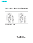
Directions for Use SpO2 Module, 8210 Series M ALAR MONITOR STAND B Y % SpO2 PULSE (BPM) CHANNEL SELECT MONITOR CHANNEL OFF Medley™ Medication Safety System SpO2 MODULE MODEL 8210 ALARIS Medical Systems, Inc. GENERAL CONTACT INFORMATION Customer Advocacy - North America Clinical and technical feedback. Phone: (800) 854-7128, Ext. 7812 E-Mail: [email protected] Technical Support - North America Maintenance and service information support; troubleshooting. United States: Phone: (858) 458-6003 (800) 854-7128, Ext. 6003 Canada: Phone: Eastern: (800) 908-9918 Western: (800) 908-9919 Customer Care - North America Instrument return, service assistance, and order placement. United States: Phone: (800) 482-4822 Canada: Phone: (800) 387-8309 TABLE OF CONTENTS INTRODUCTION ABOUT THE SpO2 MODULE . . . . . . . . . . . . . . . . . . . . . . . . . . . . . . . . . . . . . . . . . . . . . . . . . . . . . . . . . . . . . . . . . . . . . . . . . . . . . . . . . . . . . . . Principle of Operation . . . . . . . . . . . . . . . . . . . . . . . . . . . . . . . . . . . . . . . . . . . . . . . . . . . . . . . . . . . . . . . . . . . . . . . . . . . . . . . . . . . . . . . . . FEATURES AND DEFINITIONS . . . . . . . . . . . . . . . . . . . . . . . . . . . . . . . . . . . . . . . . . . . . . . . . . . . . . . . . . . . . . . . . . . . . . . . . . . . . . . . . . . . . SYMBOLS . . . . . . . . . . . . . . . . . . . . . . . . . . . . . . . . . . . . . . . . . . . . . . . . . . . . . . . . . . . . . . . . . . . . . . . . . . . . . . . . . . . . . . . . . . . . . . . . . . . . . . . . . . 1 1 4 5 GETTING STARTED WARNINGS AND CAUTIONS . . . . . . . . . . . . . . . . . . . . . . . . . . . . . . . . . . . . . . . . . . . . . . . . . . . . . . . . . . . . . . . . . . . . . . . . . . . . . . . . . . . . . . General . . . . . . . . . . . . . . . . . . . . . . . . . . . . . . . . . . . . . . . . . . . . . . . . . . . . . . . . . . . . . . . . . . . . . . . . . . . . . . . . . . . . . . . . . . . . . . . . . . . . . . . Sensors and Cables . . . . . . . . . . . . . . . . . . . . . . . . . . . . . . . . . . . . . . . . . . . . . . . . . . . . . . . . . . . . . . . . . . . . . . . . . . . . . . . . . . . . . . . . . . . MEASUREMENTS . . . . . . . . . . . . . . . . . . . . . . . . . . . . . . . . . . . . . . . . . . . . . . . . . . . . . . . . . . . . . . . . . . . . . . . . . . . . . . . . . . . . . . . . . . . . . . . . . . OPERATING FEATURES, CONTROLS AND INDICATORS . . . . . . . . . . . . . . . . . . . . . . . . . . . . . . . . . . . . . . . . . . . . . . . . . . . . . . . . . INSTALLATION . . . . . . . . . . . . . . . . . . . . . . . . . . . . . . . . . . . . . . . . . . . . . . . . . . . . . . . . . . . . . . . . . . . . . . . . . . . . . . . . . . . . . . . . . . . . . . . . . . . . . ATTACHING AND DETACHING MODULES . . . . . . . . . . . . . . . . . . . . . . . . . . . . . . . . . . . . . . . . . . . . . . . . . . . . . . . . . . . . . . . . . . . . . . . . DISPLAYS . . . . . . . . . . . . . . . . . . . . . . . . . . . . . . . . . . . . . . . . . . . . . . . . . . . . . . . . . . . . . . . . . . . . . . . . . . . . . . . . . . . . . . . . . . . . . . . . . . . . . . . . . . Main Display . . . . . . . . . . . . . . . . . . . . . . . . . . . . . . . . . . . . . . . . . . . . . . . . . . . . . . . . . . . . . . . . . . . . . . . . . . . . . . . . . . . . . . . . . . . . . . . . . . START-UP . . . . . . . . . . . . . . . . . . . . . . . . . . . . . . . . . . . . . . . . . . . . . . . . . . . . . . . . . . . . . . . . . . . . . . . . . . . . . . . . . . . . . . . . . . . . . . . . . . . . . . . . . . Powering On System . . . . . . . . . . . . . . . . . . . . . . . . . . . . . . . . . . . . . . . . . . . . . . . . . . . . . . . . . . . . . . . . . . . . . . . . . . . . . . . . . . . . . . . . . . Responding to Maintenance Reminder . . . . . . . . . . . . . . . . . . . . . . . . . . . . . . . . . . . . . . . . . . . . . . . . . . . . . . . . . . . . . . . . . . . . . . . . Selecting New Patient and Profile Options . . . . . . . . . . . . . . . . . . . . . . . . . . . . . . . . . . . . . . . . . . . . . . . . . . . . . . . . . . . . . . . . . . . . . Entering Patient ID . . . . . . . . . . . . . . . . . . . . . . . . . . . . . . . . . . . . . . . . . . . . . . . . . . . . . . . . . . . . . . . . . . . . . . . . . . . . . . . . . . . . . . . . . . . . Modifying Patient ID . . . . . . . . . . . . . . . . . . . . . . . . . . . . . . . . . . . . . . . . . . . . . . . . . . . . . . . . . . . . . . . . . . . . . . . . . . . . . . . . . . . . . . . . . . . GENERAL SETUP AND USE . . . . . . . . . . . . . . . . . . . . . . . . . . . . . . . . . . . . . . . . . . . . . . . . . . . . . . . . . . . . . . . . . . . . . . . . . . . . . . . . . . . . . . . 7 7 8 9 11 12 12 12 12 12 12 12 12 12 12 13 PROGRAMMING MONITORING MODE . . . . . . . . . . . . . . . . . . . . . . . . . . . . . . . . . . . . . . . . . . . . . . . . . . . . . . . . . . . . . . . . . . . . . . . . . . . . . . . . . . . . . . . . . . . . . . Navigating Main Display . . . . . . . . . . . . . . . . . . . . . . . . . . . . . . . . . . . . . . . . . . . . . . . . . . . . . . . . . . . . . . . . . . . . . . . . . . . . . . . . . . . . . . . Setting Alarm Limits . . . . . . . . . . . . . . . . . . . . . . . . . . . . . . . . . . . . . . . . . . . . . . . . . . . . . . . . . . . . . . . . . . . . . . . . . . . . . . . . . . . . . . . . . . . Navigating Trend Data . . . . . . . . . . . . . . . . . . . . . . . . . . . . . . . . . . . . . . . . . . . . . . . . . . . . . . . . . . . . . . . . . . . . . . . . . . . . . . . . . . . . . . . . Navigating PCA / SpO2 Trend Data . . . . . . . . . . . . . . . . . . . . . . . . . . . . . . . . . . . . . . . . . . . . . . . . . . . . . . . . . . . . . . . . . . . . . . . . . . . . Presilencing Alarm . . . . . . . . . . . . . . . . . . . . . . . . . . . . . . . . . . . . . . . . . . . . . . . . . . . . . . . . . . . . . . . . . . . . . . . . . . . . . . . . . . . . . . . . . . . . CHANNEL OPTIONS . . . . . . . . . . . . . . . . . . . . . . . . . . . . . . . . . . . . . . . . . . . . . . . . . . . . . . . . . . . . . . . . . . . . . . . . . . . . . . . . . . . . . . . . . . . . . . . Changing Limit Mode . . . . . . . . . . . . . . . . . . . . . . . . . . . . . . . . . . . . . . . . . . . . . . . . . . . . . . . . . . . . . . . . . . . . . . . . . . . . . . . . . . . . . . . . . . Changing Pulse Beep Volume . . . . . . . . . . . . . . . . . . . . . . . . . . . . . . . . . . . . . . . . . . . . . . . . . . . . . . . . . . . . . . . . . . . . . . . . . . . . . . . . . Changing SatSeconds Limit . . . . . . . . . . . . . . . . . . . . . . . . . . . . . . . . . . . . . . . . . . . . . . . . . . . . . . . . . . . . . . . . . . . . . . . . . . . . . . . . . . . POWERING OFF . . . . . . . . . . . . . . . . . . . . . . . . . . . . . . . . . . . . . . . . . . . . . . . . . . . . . . . . . . . . . . . . . . . . . . . . . . . . . . . . . . . . . . . . . . . . . . . . . . . Powering Off System . . . . . . . . . . . . . . . . . . . . . . . . . . . . . . . . . . . . . . . . . . . . . . . . . . . . . . . . . . . . . . . . . . . . . . . . . . . . . . . . . . . . . . . . . . Powering Off Module . . . . . . . . . . . . . . . . . . . . . . . . . . . . . . . . . . . . . . . . . . . . . . . . . . . . . . . . . . . . . . . . . . . . . . . . . . . . . . . . . . . . . . . . . . REVIEWING SERIAL NUMBER . . . . . . . . . . . . . . . . . . . . . . . . . . . . . . . . . . . . . . . . . . . . . . . . . . . . . . . . . . . . . . . . . . . . . . . . . . . . . . . . . . . . REVIEWING SOFTWARE VERSION . . . . . . . . . . . . . . . . . . . . . . . . . . . . . . . . . . . . . . . . . . . . . . . . . . . . . . . . . . . . . . . . . . . . . . . . . . . . . . . 15 15 16 18 20 22 23 23 24 24 25 25 25 25 25 ALARMS AND MESSAGES DEFINITIONS . . . . . . . . . . . . . . . . . . . . . . . . . . . . . . . . . . . . . . . . . . . . . . . . . . . . . . . . . . . . . . . . . . . . . . . . . . . . . . . . . . . . . . . . . . . . . . . . . . . . . . AUDIO CHARACTERISTICS . . . . . . . . . . . . . . . . . . . . . . . . . . . . . . . . . . . . . . . . . . . . . . . . . . . . . . . . . . . . . . . . . . . . . . . . . . . . . . . . . . . . . . . ALARMS . . . . . . . . . . . . . . . . . . . . . . . . . . . . . . . . . . . . . . . . . . . . . . . . . . . . . . . . . . . . . . . . . . . . . . . . . . . . . . . . . . . . . . . . . . . . . . . . . . . . . . . . . . . . MESSAGES . . . . . . . . . . . . . . . . . . . . . . . . . . . . . . . . . . . . . . . . . . . . . . . . . . . . . . . . . . . . . . . . . . . . . . . . . . . . . . . . . . . . . . . . . . . . . . . . . . . . . . . . SpO2 Module, 8210 Series Directions for Use 26 26 26 29 TABLE OF CONTENTS i MAINTENANCE SPECIFICATIONS . . . . . . . . . . . . . . . . . . . . . . . . . . . . . . . . . . . . . . . . . . . . . . . . . . . . . . . . . . . . . . . . . . . . . . . . . . . . . . . . . . . . . . . . . . . . . . . . . . CONFIGURABLE SETTINGS . . . . . . . . . . . . . . . . . . . . . . . . . . . . . . . . . . . . . . . . . . . . . . . . . . . . . . . . . . . . . . . . . . . . . . . . . . . . . . . . . . . . . . . System Settings . . . . . . . . . . . . . . . . . . . . . . . . . . . . . . . . . . . . . . . . . . . . . . . . . . . . . . . . . . . . . . . . . . . . . . . . . . . . . . . . . . . . . . . . . . . . . . . SpO2 Module Settings . . . . . . . . . . . . . . . . . . . . . . . . . . . . . . . . . . . . . . . . . . . . . . . . . . . . . . . . . . . . . . . . . . . . . . . . . . . . . . . . . . . . . . . . . CLEANING . . . . . . . . . . . . . . . . . . . . . . . . . . . . . . . . . . . . . . . . . . . . . . . . . . . . . . . . . . . . . . . . . . . . . . . . . . . . . . . . . . . . . . . . . . . . . . . . . . . . . . . . . INSPECTION REQUIREMENTS . . . . . . . . . . . . . . . . . . . . . . . . . . . . . . . . . . . . . . . . . . . . . . . . . . . . . . . . . . . . . . . . . . . . . . . . . . . . . . . . . . . . SERVICE INFORMATION . . . . . . . . . . . . . . . . . . . . . . . . . . . . . . . . . . . . . . . . . . . . . . . . . . . . . . . . . . . . . . . . . . . . . . . . . . . . . . . . . . . . . . . . . . WARRANTY . . . . . . . . . . . . . . . . . . . . . . . . . . . . . . . . . . . . . . . . . . . . . . . . . . . . . . . . . . . . . . . . . . . . . . . . . . . . . . . . . . . . . . . . . . . . . . . . . . . . . . . . 31 33 33 33 33 34 34 35 APPENDIX ACCESSORIES . . . . . . . . . . . . . . . . . . . . . . . . . . . . . . . . . . . . . . . . . . . . . . . . . . . . . . . . . . . . . . . . . . . . . . . . . . . . . . . . . . . . . . . . . . . . . . . . . . . . Nellcor® OXIMAX® Sensors . . . . . . . . . . . . . . . . . . . . . . . . . . . . . . . . . . . . . . . . . . . . . . . . . . . . . . . . . . . . . . . . . . . . . . . . . . . . . . . . . . . . . Nellcor® Patient Cables . . . . . . . . . . . . . . . . . . . . . . . . . . . . . . . . . . . . . . . . . . . . . . . . . . . . . . . . . . . . . . . . . . . . . . . . . . . . . . . . . . . . . . . . Nellcor® Sensor Accuracy Grid . . . . . . . . . . . . . . . . . . . . . . . . . . . . . . . . . . . . . . . . . . . . . . . . . . . . . . . . . . . . . . . . . . . . . . . . . . . . . . . . ii TABLE OF CONTENTS 37 37 39 39 SpO2 Module, 8210 Series Directions for Use INTRODUCTION INTRODUCTION About the SpO2 Module The Medley™ SpO2 Module is indicated for continuous, noninvasive monitoring of functional oxygen saturation of arterial hemoglobin (SpO2) and pulse rate measured by an SpO2 sensor. The SpO2 Module and accessories are indicated for use with adult, pediatric and neonatal patients during both no motion and motion conditions, and for patients who are well or poorly perfused in hospitals and hospital-type facilities. Only 1 SpO2 Module can be connected to a Medley™ Point-ofCare Unit. NOTE: The Medley™ Point-of-Care Unit was formerly known as the Medley™ Programming Module. The SpO2 Module uses a Nellcor® DOC-10 patient cable and a wide variety of Nellcor® OXIMAX® series sensors. The Nellcor® cable and sensors are designed for use with the Model 8210 SpO2 Module. For specific directions for use, refer to the cable and sensor packaging. Contraindications: The SpO2 Module with Nellcor® DOC–10, OC-3 patient cables and Nellcor® OXIMAX® series sensors are contraindicated for use as an apnea monitor. This document provides directions for use for the Medley™ SpO2 Module, Model 8210. WARNING Read all instructions, for both the SpO2 Module and Point-of-Care Unit, before using the Medley™ System. Principle of Operation The operation of the Medley™ SpO2 Module is based on the principles of pulse oximetry. Oxyhemoglobin and deoxyhemoglobin differ in their absorption of red and infrared light (spectrophotometry). The volume of arterial blood in tissue and the light absorbed by the blood changes during the pulse (plethysmography). A pulse oximeter determines SpO2 by passing red and infrared light into an arteriolar bed and measuring changes in light absorption during the pulsatile cycle. Red and infrared low-voltage light-emitting diodes (LED) in the oximetry sensor serve as light sources; a photo diode serves as the photo detector. SpO2 Module, 8210 Series Directions for Use INTRODUCTION 1 About the SpO2 Module (Continued) Principle of Operation (Continued) Because oxyhemoglobin and deoxyhemoglobin differ in light absorption, the amount of red and infrared light absorbed by blood is related to hemoglobin oxygen saturation to identify the oxygen saturation of arterial hemoglobin, the monitor uses the pulsatile nature of arterial flow. During systole, a new pulse of arterial blood enters the vascular bed, and blood volume and light absorption increase. During diastole, blood volume and light absorption reach their lowest point. The SpO2 Module bases its SpO2 measurements on the difference between maximum and minimum absorption (measurements at systole and diastole). By doing so, it focuses on light absorption by pulsatile arterial blood, eliminating the effects of nonpulsatile absorbers; such as, venous blood, tissue and bone. Because light absorption by hemoglobin is wavelength dependent and the mean wavelength of LEDs varies, an oximeter must know the mean wavelength of the sensor’s red LED to accurately measure SpO2. During monitoring, the instrument’s software selects coefficients that are appropriate for the wavelength of that individual sensor’s red LED. Those coefficients are then used to determine SpO2. To compensate for differences in tissue thickness, the light intensity of the sensor’s LEDs is adjusted automatically. The SpO2 Module measures functional saturation (oxygenated hemoglobin expressed as a percentage of the hemoglobin that can transport oxygen). It does not detect significant amounts of dysfunctional hemoglobin; such as, carboxyhemoglobin or methemoglobin. In contrast, hemoximeters (such as, IL482) report fractional saturation (oxygenated hemoglobin expressed as a percentage of all measured hemoglobin, including measured dysfunctional hemoglobin). To compare functional saturation measurements to those from an instrument that measures fractional saturation, fractional measurements must be converted as follows: functional saturation= fractional saturation x 100 100 - (%carboxyhemoglobin + %methemoglobin) 2 INTRODUCTION SpO2 Module, 8210 Series Directions for Use About the SpO2 Module (Continued) INTRODUCTION Principle of Operation (Continued) When saturation is calculated from a blood gas partial pressure of oxygen (PO2), the calculated value may differ from the SpO2 measurement of the SpO2 Module, this usually occurs because the calculated saturation was not appropriately corrected for the effects of variables that shift the relationship between PO2 and pH, temperature, the partial pressure of carbon dioxide (PCO2), 2,3-DPG, and fetal hemoglobin. To compare functional saturation measurements to those from an instrument that measures fractional saturation, fractional measurements must be converted as follows: Oxyhemoglobin Dissociation Curve 100 ¯ ¯ Saturation (%) ¯ pH Temperature PCO2 2,3-DPG Fetal Hb ¬ 50 ® ¯ ¯ ¯ pH Temperature PCO2 2,3-DPG 0 50 100 PO2 (mmHg) SpO2 Module, 8210 Series Directions for Use INTRODUCTION 3 Features and Definitions Reference the “Alarms, Errors, Messages” chapter of the Medley™ Point-of-Care Unit Directions for Use (DFU) for the definitions of various alerts. Reference the Point-of-Care Unit DFU for system features and definitions. % SpO2 Alarm Limits Upper and lower saturation alarm limits are displayed. % SpO2 Display Functional arterial hemoglobin oxygen saturation is displayed in units of percentage SpO2. Limit Mode Displays either adult or neonatal monitoring mode. Pleth Waveform Plethysmographic (pleth) waveform is a graphic representation of changes in extremity blood volume during events of cardiac cycle. Presilence Alarms can be presilenced for 120 seconds. Presilence alarm can be cancelled before 120 seconds are complete. Pulse Beat Volume Can be configured to be off or to a volume level of 1, 2 or 3. Pulse Rate Displayed in beats per minute (bpm). Pulse Rate Alarm Limits Upper and lower limits are displayed. SatSeconds SatSeconds limits controls time %SpO2 level may fall outside alarm limits before an audible alarm sounds. Method of calculation is as follows: Number of percentage points %SpO2 falls outside of alarm limit is multiplied by number of seconds %SpO2 level remains outside that limit. Points x Seconds = SatSeconds Points = %SpO2 percentage points outside of limit Seconds = number of seconds %SpO2 remains at that point outside of limit Saturation levels may fluctuate rather than remain steady for a period of several seconds. Often, %SpO2 levels may fluctuate above and below alarm limit, reentering nonalarm range several times. During such fluctuations, SpO2 Module integrates number of %SpO2 points, both positive and negative, until either SatSeconds limit (SatSeconds time setting) is reached or %SpO2 level returns to within a normal range and remains there. SatSeconds “Safety Net” is for patients with saturation levels having frequent excursions below limit but not staying below limit long enough for SatSeconds time setting to be reached. When 3 or more limit violations occur within 60 seconds, an alarm sounds, even if SatSeconds time setting has not been reached. 4 INTRODUCTION SpO2 Module, 8210 Series Directions for Use Features and Definitions (Continued) With SatSeconds Alarm Management Technology, upper and lower alarm limits are set in the same way as with traditional alarm management. A SatSeconds limit can be set to allow monitoring of %SpO2 below selected low alarm limit for a period of time before an audible alarm sounds. Trend Data A tabular display of %SpO2 and Pulse Rate. Display shows alarm conditions for time period displayed and average, high and low values. Data is stored for 24 hours. INTRODUCTION SatSeconds Alarm Management Technology Symbols Attention: Refer to accompanying documentation. + 75 Canadian and U.S. Certification Mark: Products bearing this mark have been tested and certified in accordance with applicable U.S. and Canadian electrical safety and performance standards (CSA C22.2 No. 601.1, UL 60601–1). Consult operating instructions. Electrical Shock Protection Rating: Type BF applied part. IPX1 Protection against fluid ingress: Drip Proof IUI Connector: Inter-Unit Interface connector used to establish power and communications between Point-of-Care Unit and attached modules. Manufacturing Date: Number adjacent to symbol indicates month and year of manufacture. MM-YYYY CAUTION: Federal (U.S.A.) law restricts this device to sale by or on order of a physician. Do not use if package is damaged. SpO2 Module, 8210 Series Directions for Use INTRODUCTION 5 T H I S PA G E I N T E N T I O N A L LY LEFT BLANK 6 INTRODUCTION SpO2 Module, 8210 Series Directions for Use GETTING STARTED Warnings and Cautions Warnings and Cautions provided throughout this Directions for Use (DFU) provide information needed to safely and effectively use the Medley™ SpO2 Module and accessories. Medley™ System Warnings and Cautions, and definitions, are covered in the Point-of-Care Unit DFU. GETTING STARTED General WARNINGS • The SpO2 Module is NOT to be used as an apnea monitor. • Pulse oximetry readings and pulse signal can be affected by certain ambient conditions, sensor application errors and certain patient conditions. • The SpO2 Module is intended only as an adjunct in patient assessment. It must be used in conjunction with clinical signs and symptoms. • The SpO2 Module should be considered an early warning device. As a trend towards patient deoxygenation is indicated, blood samples should be analyzed by a laboratory CO-Oximeter to completely understand the patient’s condition. • Interfering Substances: Carboxyhemoglobin and methemoglobin may erroneously increase readings. The level of increase is approximately equal to the amount of carboxyhemoglobin present. Dyes, or any substance containing dyes, that change usual arterial pigmentation may cause erroneous readings. • Do not use the SpO2 Module or sensors during Magnetic Resonance Imaging (MRI). • The SpO2 Module is not rated for defibrillation use. Disconnect the sensor from the patient or patient cable from the module prior to defibrillation. • If an alarm condition on the SpO2 Module occurs while the audio alarm is silenced, the only alarm indications will be visual displays and symbols related to the alarm condition. SpO2 Module, 8210 Series Directions for Use GETTING STARTED 7 Warnings and Cautions (Continued) General (Continued) WARNINGS • Check alarm limits each time the SpO2 Module is used, to ensure they are appropriate for the patient being monitored. • Do not lift the SpO2 Module by the cable or power cord because the cable or cord could disconnect from the instrument, causing it to drop on the patient. Do not place the SpO2 Module in any position that might cause it to fall on the patient. CAUTION To ensure Electromagnetic Compliance Integrity, accessories including external communication systems (hospital data communication equipment and/or Nurse call systems) must be certified to applicable standards: • IEC 60601-1 (Electromedical Equipment) or • IEC 950 (Data Processing Equipment) NOTE: Nurse Call systems must be certified to UL 1069 (Hospital Signaling and Nurse Call Equipment) or comply with requirements specified in IEC 60601-1. Compliance with the electromagnetic compatibility standard (IEC 60601-1-2) is a function of all interconnected equipment including cabling; as such, it is the responsibility of the user to ensure external equipment complies with the applicable EMC standards. Failure to verify such external equipment meets applicable EMC standards may result in degraded electromagnetic compatibility. Sensors and Cables WARNINGS • Inspect the SpO2 sensor site regularly to ensure correct sensor positioning, application and site integrity. Tissue damage could occur over prolonged time periods, depending on the patient profile (such as, neonates) and method of application. Refer to the sensor instructions for additional information. 8 GETTING STARTED SpO2 Module, 8210 Series Directions for Use Warnings and Cautions (Continued) Sensors and Cables (Continued) WARNINGS • Carefully route patient cabling to reduce the possibility of patient entanglement or strangulation. GETTING STARTED • Before use, read sensor directions for use, including all warnings, cautions and instructions. • Use only approved Nellcor® OXIMAX® sensors and DOC–10, OC–3 pulse oximetry cables. Use of sensors, transducers, cables and accessories other than those specified may cause improper SpO2 Module performance resulting in inaccurate readings, increased emission and/or decreased immunity, and degraded electromagnetic compatibility performance of the SpO2 Module. • Do not use a sensor, cable, connector or SpO2 Module that appears damaged. Do not use a sensor with exposed optical components. Do not immerse or wet the sensor or cable. Clean per manufacturer’s instructions (refer to Nellcor® OXIMAX® sensors instructions for use). • The sensor disconnect error message and associated alarm indicate the sensor is either disconnected or the wiring is faulty. Check the sensor connection and, if necessary, replace the sensor and/or pulse oximetry cable. Measurements If the accuracy of any measurement does not seem reasonable, first check the patient’s vital signs by alternate means and then check the SpO2 Module to ensure it is functioning properly. An inaccurate measurement may be caused by: • Incorrect sensor application or use. • Significant levels of dysfunctional hemoglobins; such as, carboxyhemoglobin or methemoglobin. • Intravascular dyes such as, indocyanine green or methylene blue. SpO2 Module, 8210 Series Directions for Use GETTING STARTED 9 Measurements (Continued) • Exposure to excessive illumination; such as, a surgical lamp (especially one with a xenon light source), bilirubin lamp, fluorescent light, infrared heating lamp or direct sunlight. NOTE: Exposure to excessive illumination can be corrected by covering the sensor with a dark or opaque material. • Prolonged and/or excessive patient movement. • Venous pulsations. • Sensor placed on an extremity with a blood pressure cuff, arterial catheter, intravascular line or other causes of insufficient perfusion. • Nail aberrations, nail polish, fungus, etc. Remove nail polish and/or move sensor to an unaffected site. • Placement is too close to electrosurgery equipment. • Defibrillation. The loss of a pulse signal can occur in any of the following situations: • Sensor is too tight. • Exposure to excessive illumination; such as, a surgical lamp (especially one with a xenon light source), bilirubin lamp, fluorescent light, infrared heating lamp or direct sunlight. • Sensor placed on an extremity with a blood pressure cuff, arterial catheter, intravascular line or other causes of insufficient perfusion. • Patient has hypotension, severe vasoconstriction, severe anemia or hypothermia, is in cardiac arrest or is in shock. • There is arterial occlusion proximal to sensor. • Placement is too close to electrosurgery equipment. 10 GETTING STARTED SpO2 Module, 8210 Series Directions for Use Operating Features, Controls and Indicators Status Indicators Alarm Infusing Standby (red) (green) (yellow) IUI Connector, Right IUI Connector, Left ALARM GETTING STARTED (not visible) MON ITOR %SpO2 Display STA ND BY Pulse Bar Display Pulse Rate Display %Sp O2 PUL Channel (Module) Message Display SE ( BPM ) Channel (Module) Identification Channel (Module) Select Key: CHA N SEL NEL ECT When pressed, selects corresponding module for patient monitoring and setup. MON ITOR CHA NN OFF EL Monitor Key: When pressed, begins patient monitoring. Channel (Module) Off Key: When pressed and held until a beep is heard, stops operation of that module, deselects that module, and if only that module had been operating, system powers down. Repeat for other operating modules to power off each module. Module Release Latch: When pressed, allows module to be removed. Patient Cable Connector SpO2 Module, 8210 Series Directions for Use GETTING STARTED 11 Installation Instruments are tested and calibrated before they are packaged for shipment. To ensure proper operation after shipment, it is recommended that an incoming inspection be performed before placing the instrument in use. Prior to placing the Medley™ System in use: Perform check-in procedure per Medley™ Maintenance Software/User Manual (Model 8970C, or later). Attaching and Detaching Modules Reference the Medley™ Point-of-Care Unit DFU. Displays The displays illustrated throughout this document are for illustration purposes only. The display content will vary, depending on configuration settings and other variables. Main Display Reference the Medley™ Point-of-Care Unit DFU. Start-Up Reference the Medley™ Point-of-Care Unit DFU for the following procedures: Powering On System Responding to Maintenance Reminder Selecting New Patient and Profile Options Entering Patient ID Modifying Patient ID 12 GETTING STARTED SpO2 Module, 8210 Series Directions for Use General Setup and Use 1. Attach Nellcor® patient cable to SpO2 Module. Ensure secure connection and patient cable is not twisted, sliced or frayed. Attach Nellcor® OXIMAX® sensors to Nellcor® patient cable. Refer to sensor’s directions for use for detailed instructions. 3. Ensure sensor’s red LED is on. 4. Attach sensor to patient. Refer to sensor’s directions for use for detailed instructions. 5. Verify high and low alarm rates for SpO2 and pulse rate are correct for patient by selecting CHANNEL SELECT key. Use only approved Nellcor® OXIMAX® sensors and DOC–10, OC–3 pulse oximetry cables. Use of sensors, transducers, cables and accessories other than those specified may cause improper SpO2 Module performance resulting in inaccurate readings, increased emission and/or decreased immunity, and degraded electromagnetic compatibility performance of the SpO2 Module. NOTES: • SEARCHING may appear in Channel Message Display until SpO2 and pulse readings have stabilized (approximately 15 seconds). • If sensor is not attached to a site after powering up, module will display SENSOR OFF. If sensor is not attached during message display, module will go into sleep mode. To begin monitoring once module is in this mode, press MONITOR key. 6. Monitor patient. 7. After patient monitoring is complete, remove sensor from patient according to hospital protocol. 8. Turn off SpO2 Module by pressing and holding CHANNEL OFF key for 1 second. NOTE: Module will initiate power down when CHANNEL OFF key is released. SpO2 Module, 8210 Series Directions for Use GETTING STARTED 13 GETTING STARTED 2. WARNING T H I S PA G E I N T E N T I O N A L LY LEFT BLANK 14 GETTING STARTED SpO2 Module, 8210 Series Directions for Use PROGRAMMING Monitoring Mode Navigating Main Display 1. Attach SpO2 Module to Point-of-Care Unit. 2. Power on system by pressing SYSTEM ON key on Pointof-Care Unit. • NEW PATIENT? screen appears. Midtown Hospital NEW PATIENT ? Yes “Yes” Clears Previous Patient Data No >Select Yes or No DISPLAY CONTRST To clear previous SpO2 trend data, press Yes soft key. PROGRAMMING 3. OR To retain previous SpO2 trend data, press No soft key. • Main Display appears. OR Midtown Hospital Adult ICU A SPO2 AUDIO ADJUST If Guardrails® Safety Software is enabled, profiles screen appears. • 4. 1 of 2 Adult ICU View Adult General Care View Neonatal View If Yes is selected, a prompt to confirm last profile selected appears. Peds ICU View Neonatal ICU View If No is selected, a prompt to choose a profile appears. >Select a Profile Confirm NOTE: When Guardrails® Safety Software is enabled: • Midtown Hospital Profiles CONFIRM PAGE DOWN Attach patient cable and sensor as described in “Getting Started” chapter, “General Setup and Use” section. SpO2 Module, 8210 Series Directions for Use PROGRAMMING 15 Monitoring Mode (Continued) Navigating Main Display (Continued) 5. To view SPO2 Main display, press CHANNEL SELECT key. NOTE: To prevent the screen from reverting to the Main Display, press the ENTER key within 30 seconds after the SPO2 Main screen is initially displayed. A Adult Mode SPO2 Main % SPO2 97 Off 90 PULSE RATE 82 150 50 - pleth waveform 0 100 SatSeconds (% to Alarm) >Press ENTER to Retain Current View TREND 6. To return to Main Display, press MAIN SCREEN soft key. LIMITS MAIN SCREEN Midtown Hospital Adult ICU A SPO2 AUDIO ADJUST Setting Alarm Limits 1. Press CHANNEL SELECT key. A SPO2 Main % SPO2 97 Off 90 PULSE RATE 82 150 50 Adult Mode 0 100 SatSeconds (% to Alarm) >Press ENTER to Retain Current View TREND 2. Press LIMITS soft key. LIMITS MAIN SCREEN A Adult Alarm Limits %SPO2 HIGH %SPO2 LOW PULSE HIGH PULSE LOW Off 90 150 50 >Select Parameter Limit Confirm 16 PROGRAMMING SpO2 Module, 8210 Series Directions for Use Monitoring Mode (Continued) Setting Alarm Limits (Continued) 3. To change a limit setting, press soft key next to applicable parameter. A Adult Alarm Limits %SPO2 HIGH • Selected parameter is highlighted. %SPO2 LOW • Display prompts for a value to be entered. PULSE HIGH PULSE LOW Off 90 150 50 >Enter High %SPO2 Limit Confirm 4. Enter a numeric value for selected alarm limit. A Adult Alarm Limits NOTES: • The %SPO2 HIGH limit can be Off or a numeric value. %SPO2 LOW PULSE HIGH PULSE LOW _98 90 150 50 Off PROGRAMMING Numeric values can be entered using the keypad or the and keys. After the field containing a valid value has been highlighted for 3 seconds, the display prompt changes to >Press CONFIRM to Apply Changes. %SPO2 HIGH >Press CONFIRM to Apply Changes • Pressing Confirm soft key will confirm the alarm limits Confirm and return to the SPO2 Main display. 5. To move to next limit, press ENTER key on Point-of-Care Unit. A Adult Alarm Limits %SPO2 HIGH %SPO2 LOW PULSE HIGH PULSE LOW 98 _90 150 50 >Enter Low %SPO2 Limit Confirm 6. To confirm alarm settings and return to SPO2 Main display, press Confirm soft key. A SPO2 Main % SPO2 97 Off 90 PULSE RATE 82 150 50 0 Adult Mode 100 SatSeconds (% to Alarm) >Press ENTER to Retain Current View TREND SpO2 Module, 8210 Series Directions for Use LIMITS MAIN SCREEN PROGRAMMING 17 Monitoring Mode (Continued) Setting Alarm Limits (Continued) 7. To return to Main Display, press MAIN SCREEN soft key. Midtown Hospital Adult ICU A SPO2 AUDIO ADJUST Navigating Trend Data 1. To view SPO2 Main display, press CHANNEL SELECT key. A Adult Mode SPO2 Main % SPO2 PULSE RATE 97 Off 90 82 150 50 0 100 SatSeconds (% to Alarm) >Press ENTER to Retain Current View TREND 2. To view Trend Data, press TREND soft key. A Trend Data Adult Mode 09:00 PULSE 2001-07-06 SPO2 MAX AVG TIME NOTES: • Tabular information will not be updated while the Trend Data view is displayed. The tabular data will be updated, using the new trend data stored in the SpO2 Module, after leaving the Trend Data view. To view the latest data, return to the Trend Data view. • will only be displayed if a limit violation occurred for the indicated limit in the time window. • If there are no SPO2 or PULSE rate values for the time period displayed, dashes (---) will be displayed. • Six data collection periods are displayed on a screen page. 18 PROGRAMMING MAIN SCREEN LIMITS 07:01 97 97 05:01 97 03:01 97 MIN 100 90 100 90 100 90 100 88 01:01 --97 100 90 09:01 23:01 ZOOM: 120 60 30 82 MAX MIN 152 50 150 50 150 50 150 50 --82 150 50 AVG 82 82 82 5 1 minutes >Press UP/DOWN Keys to Move Cursor. ZOOM SPO2 MAIN PAGE DOWN SpO2 Module, 8210 Series Directions for Use Monitoring Mode (Continued) Navigating Trend Data (Continued) 3. To navigate from page to page, press PAGE UP and PAGE DOWN soft keys. NOTE: The last page does not have a PAGE DOWN soft key and the first page does not have a PAGE UP soft key. When moving from page to page, the cursor (highlight) always displays on the third row of data. 4. To scroll data 1 row at a time, press Point-of-Care Unit. or key on A Trend Data Adult Mode 09:00 PULSE 2001-07-06 SPO2 MAX AVG TIME AVG MIN 07:01 97 05:01 97 03:01 97 100 90 100 90 100 88 01:01 --97 97 100 90 100 90 23:01 21:01 ZOOM: 120 60 82 150 50 150 50 150 50 --82 82 150 50 150 50 82 82 30 5 MAX MIN 1 minutes 5. To change TIME period for data collection period, move cursor to desired time period and press ZOOM soft key. A Trend Data Adult Mode TIME AVG MIN 06:01 97 97 05:01 97 04:01 97 97 07:01 • New time period is highlighted. 09:00 PULSE 2001-07-06 SPO2 MAX AVG NOTE: Repeated pressing of the ZOOM soft key cycles through the time period choices. PAGE DOWN SPO2 MAIN ZOOM 03:01 02:01 ZOOM: 100 90 100 90 100 90 100 88 100 88 82 82 82 82 82 --120 60 PROGRAMMING >Press UP/DOWN Keys to Move Cursor. MAX MIN 150 50 150 50 150 50 150 50 150 50 --30 5 1 minutes >Press UP/DOWN Keys to Move Cursor. ZOOM 6. To return to SPO2 Main display, press SPO2 MAIN soft key. A SPO2 MAIN SPO2 Main % SPO2 97 Off 90 PULSE RATE 82 150 50 0 PAGE DOWN Adult Mode 100 SatSeconds (% to Alarm) >Press ENTER to Retain Current View TREND SpO2 Module, 8210 Series Directions for Use LIMITS MAIN SCREEN PROGRAMMING 19 Monitoring Mode (Continued) Navigating Trend Data (Continued) 7. To return to Main Display, press MAIN SCREEN soft key. Midtown Hospital Adult ICU A SPO2 AUDIO ADJUST Navigating PCA / SpO2 Trend Data To navigate the trend data when a Medley™ PCA Module is present, perform the following steps. 1. To view SPO2 Main display, press CHANNEL SELECT key on SpO2 Module. A Adult Mode SPO2 Main % SPO2 97 Off 90 PULSE RATE 82 150 50 0 100 SatSeconds (% to Alarm) >Press ENTER to Retain Current View TREND 2. To access option to view trend data, press OPTIONS key on Point-of-Care Unit. LIMITS MAIN SCREEN A Channel Options Limit Mode: Adult Pulse Beep Volume: Off SatSeconds Limits: 10 PCA/SpO2 Trend data >Select an Option or EXIT EXIT 20 PROGRAMMING SpO2 Module, 8210 Series Directions for Use Monitoring Mode (Continued) Navigating PCA / SpO2 Trend Data (Continued) 3. To view Trend Data, press PCA/SpO2 Trend data soft key. A Morphine 1mg/mL • will only be displayed if a limit violation occurred for the indicated limit in the time window. • If there are no SPO2 or PULSE rate values for the time period displayed, dashes (---) will be displayed. • Six data collection periods are displayed on a screen page. AVG 97 97 08:02 1.2 97 08:03 5.01 97 82 08:04 --2 --97 --82 08:05 ZOOM: 120 60 30 5 1 minutes >Press UP/DOWN Keys to Move Cursor. PAGE DOWN SPO2 MAIN ZOOM PROGRAMMING 4. Tabular information will not be updated while the Trend Data view is displayed. The tabular data will be updated, using the new trend data stored in the SpO2 Module, after leaving the Trend Data view. To view the latest data, return to the Trend Data view. PULSE AVG 82 82 82 08:01 • SPO2 — 2.55 08:00 NOTES: 09:00 TOTAL 2003-06-06 DOSE (mg) TIME To navigate from page to page, press PAGE UP and PAGE DOWN soft keys. NOTE: The last page does not have a PAGE DOWN soft key and the first page does not have a PAGE UP soft key. When moving from page to page, the cursor (highlight) always displays on the third row of data. 5. To scroll data 1 row at a time, press Point-of-Care Unit. or key on NOTE: The cursor (highlight) remains on the third row of data. A Morphine 1mg/mL 09:00 TOTAL 2003-06-06 DOSE (mg) TIME SPO2 PULSE AVG AVG 08:01 2.55 97 08:02 1.2 97 82 82 08:03 5.01 97 82 08:04 --2 --97 --82 08:05 --- 08:06 ZOOM: 120 60 --30 5 --1 minutes >Press UP/DOWN Keys to Move Cursor. 6. To change TIME period for data collection period, move cursor to desired time period and press ZOOM soft key. NOTE: Repeated pressing of the ZOOM soft key cycles through the time period choices. • New time period is highlighted. A PAGE DOWN SPO2 MAIN ZOOM Morphine 1mg/mL 09:00 TOTAL 2003-06-06 DOSE (mg) TIME SPO2 PULSE AVG AVG 08:01 2.55 97 08:06 1.2 97 82 82 08:11 5.01 97 82 08:16 --2 --97 --82 08:21 --- 08:26 ZOOM: 120 60 --30 5 --1 minutes >Press UP/DOWN Keys to Move Cursor. ZOOM SpO2 Module, 8210 Series Directions for Use SPO2 MAIN PAGE DOWN PROGRAMMING 21 Monitoring Mode (Continued) Navigating PCA / SpO2 Trend Data (Continued) 7. To return to SPO2 Main display, press SPO2 MAIN soft key. A SPO2 Main % SPO2 97 Off 90 PULSE RATE 82 150 50 0 Adult Mode 100 SatSeconds (% to Alarm) >Press ENTER to Retain Current View TREND 8. To return to Main Display, press MAIN SCREEN soft key. LIMITS MAIN SCREEN Midtown Hospital Adult ICU A SPO2 AUDIO ADJUST Presilencing Alarm 1. To presilence alarm, press SILENCE key on Point-of-Care Unit. Midtown Hospital Adult ICU A SPO2 NOTE: All monitoring alarms will be silenced for 120 seconds. Infusion alarms will not be silenced. AUDIO ADJUST 2. To cancel presilence alarm and return to alarmable mode: • Press CHANNEL SELECT key on SpO2 Module. A SPO2 Main % SPO2 97 Off 90 PULSE RATE 82 150 50 Adult Mode • Press CANCEL SILENCE soft key. 0 100 SatSeconds (% to Alarm) >Press ENTER to Retain Current View TREND 22 PROGRAMMING CANCEL SILENCE LIMITS MAIN SCREEN SpO2 Module, 8210 Series Directions for Use Channel Options To access Channel Options: a. Press CHANNEL SELECT key on SpO2 Module. A Adult Mode SPO2 Main % SPO2 97 Off 90 PULSE RATE 82 150 50 0 100 SatSeconds (% to Alarm) >Press ENTER to Retain Current View TREND b. Press OPTIONS key on Point-of-Care Unit. LIMITS MAIN SCREEN A Channel Options Limit Mode: Adult Pulse Beep Volume: Off SatSeconds Limits: 10 PROGRAMMING >Select an Option or EXIT EXIT Changing Limit Mode 1. Access Channel Options display and press Limit Mode soft key. 2. To change Limit Mode Setup, press either Adult or Neonatal soft key. A Limit Mode Setup Adult NOTE: If a profiles option is being used for programming, the Limit Mode cannot be changed. Neonatal >Select an Option or EXIT EXIT 3. If Limit Mode is not changed, press EXIT soft key to return to SPO2 Main display and press OPTIONS key on Pointof-Care Unit to view other options. A SPO2 Main % SPO2 97 Off 90 PULSE RATE 82 150 50 0 Adult Mode 100 SatSeconds (% to Alarm) >Press ENTER to Retain Current View TREND SpO2 Module, 8210 Series Directions for Use LIMITS MAIN SCREEN PROGRAMMING 23 Channel Options (Continued) Changing Pulse Beep Volume 1. Access Channel Options display and press Pulse Beep Volume soft key. A Test Pulse Beep Volume Off NOTE: In the illustrated display, the Pulse Beep Volume is Off. To display the volume options, press the Louder soft key. The selectable options are Off, Level 1, Level 2 and Level 3. Louder Softer >Press CONFIRM Confirm 2. To increase volume, press Louder soft key until desired volume level is attained. To test volume level (when not attached to patient), press Test soft key. To turn off pulse beep entirely, press Off soft key. NOTE: Audio sounds for 1 cycle. A Test Pulse Beep Volume Off Louder Softer >Press CONFIRM Confirm 3. To return SPO2 Main display, press Confirm soft key. A Adult Mode SPO2 Main % SPO2 97 Off 90 PULSE RATE 82 150 50 0 100 SatSeconds (% to Alarm) >Press ENTER to Retain Current View TREND CANCEL SILENCE LIMITS MAIN SCREEN Changing SatSeconds Limit 1. Access Channel Options display and press SatSeconds Limits soft key. 2. To change SatSeconds, press either Increase or Decrease soft key. Selectable options are 10, 25, 50 and 100 seconds, or Off. A SatSeconds Setup 10 Increase SPO2 Seconds Decrease Off >Press CONFIRM CONFIRM 24 PROGRAMMING SpO2 Module, 8210 Series Directions for Use Channel Options (Continued) Changing SatSeconds Limit (Continued) 3. To return SPO2 Main display, press Confirm soft key. A SPO2 Main % SPO2 97 Off 90 PULSE RATE 82 150 50 0 Adult Mode 100 SatSeconds (% to Alarm) >Press ENTER to Retain Current View TREND CANCEL SILENCE LIMITS MAIN SCREEN Powering Off Reference the Medley™ Point-of-Care Unit DFU for the following procedures: PROGRAMMING Powering Off System Powering Off Module Reviewing Serial Number Reference the Medley™ Point-of-Care Unit DFU. Reviewing Software Version Reference the Medley™ Point-of-Care Unit DFU. SpO2 Module, 8210 Series Directions for Use PROGRAMMING 25 T H I S PA G E I N T E N T I O N A L LY LEFT BLANK 26 PROGRAMMING SpO2 Module, 8210 Series Directions for Use ALARMS AND MESSAGES To enhance safety and ease of operation, the Medley™ System provides a full range of audio and visual alarms, errors, and messages. Definitions Reference the Medley™ Point-of-Care Unit Directions for Use (DFU). Audio Characteristics Reference the Medley™ Point-of-Care Unit DFU. WARNING If an alarm condition on the SpO2 Module occurs while the audio alarm is silenced, the only alarm indication will be a visual display and symbol related to the alarm condition. Alarms Meaning Response Bad Sensor Broken, unknown or nonsystem sensor or patient cable attached. Check sensor and patient cable. Confirm correct sensor and patient cable are chosen. Reference “Appendix” chapter, “Accessories” section for a list of sensors designed for use with this module. Check Sensor - Electrical or Optical Interference External interference on sensor. Check sensor. Identify source of external interference if other than sensor. Check Sensor - High Pulse Amplitude Artifact interfering with pulse reading. Check sensor - relocate sensor to a site with less artifact interference. Check Sensor - Excessive Ambient Light Light interference on sensor. Check sensor. Remove or reduce lighting. Cover or reposition sensor. Check Sensor - Motion Interference Patient’s motion has inhibited monitoring. Check sensor. Move sensor to a site with less motion. SpO2 Module, 8210 Series Directions for Use ALARMS AND MESSAGES 27 ALARMS AND MESSAGES Alarm Alarms (Continued) Alarm Meaning Response Check Sensor - No signal Sensor not properly attached to patient cable or patient cable not properly attached to SpO2 Module. Attach sensor to patient cable or attach patient cable to SpO2 Module. Check Sensor - Weak Pulse Patient’s low perfusion has inhibited monitoring. Check sensor. Move sensor to a better perfused site. Check Sensor - Weak Signal Low quality of signal being measured. Check sensor. Confirm correct sensor placement. Move sensor to a better perfused site. High Pulse Rate Alarm High pulse rate alarm limit has been exceeded. Access patient’s condition. Confirm correct alarm limit values are selected. High SpO2 Alarm High SpO2 alarm limit has been exceeded. Access patient’s condition. Confirm correct alarm limit values are selected. Low Pulse Rate Alarm Low pulse rate alarm limit has been exceeded. Access patient’s condition. Confirm correct alarm limit values are selected. Low SpO2 Alarm Low SpO2 alarm limit has been exceeded. Access patient’s condition. Confirm correct alarm limit values are selected. No Sensor Sensor not properly attached to patient cable or patient cable not properly attached to SpO2 Module. Attach sensor to patient cable or attach patient cable to SpO2 Module. No Signal Failure to find a patient signal after 30 seconds of searching. Check sensor. Confirm correct sensor placement. Remove Module (Max=1) More than 1 SpO2 Module attached. Remove additional SpO2 Module. Sensor Off Sensor not properly attached to patient. Reattach sensor to patient. 28 ALARMS AND MESSAGES SpO2 Module, 8210 Series Directions for Use Messages Message Meaning Response Check Sensor - Electrical or Optical Interference External interference on sensor. Check sensor. Identify source of external interference if other than sensor. Check Sensor - High Pulse Amplitude Artifact interfering with pulse reading. Check sensor. Relocate sensor to a site with less artifact interference. Check Sensor - Excessive Ambient Light Light interference on sensor. Check sensor. Remove or reduce lighting. Cover or reposition sensor. Check Sensor - Motion Interference Patient’s motion has inhibited monitoring. Check sensor. Move sensor to a site with less motion. Check Sensor - Weak Pulse Patient’s low perfusion has inhibited monitoring. Check sensor. Move sensor to a better perfused site. Check Sensor - Weak Signal Low quality of signal being measured. Check sensor. Confirm correct sensor placement. Move sensor to a better perfused site. ALARMS AND MESSAGES SpO2 Module, 8210 Series Directions for Use ALARMS AND MESSAGES 29 T H I S PA G E I N T E N T I O N A L LY LEFT BLANK 30 ALARMS AND MESSAGES SpO2 Module, 8210 Series Directions for Use MAINTENANCE The Medley™ System Technical Service Manual is available from ALARIS Medical Systems. It includes routine service schedules, interconnect diagrams, component parts lists and descriptions, test procedures, and other technical information, to assist qualified service personnel in repair and maintenance of the instrument’s repairable components. Maintenance procedures are intended to be performed only by qualified personnel, using the service manual and Medley™ Maintenance Software. Specifications Accuracy and Motion Tolerance: Pulse Rate: Low Perfusion1 Motion No Motion1 Functional Saturation: Low Perfusion1 Motion2 Adults and Neonates No Motion3 Adults Neonates 20 - 250 bpm, ±3 digits normal physiologic range (55 -125 bpm) ±5 digits 20 - 250 bpm, ±3 digits 70 - 100%, ±2 digits 70 - 100%, ±3 digits 70 - 100%, ±2 digits 70 - 100%, ±3 digits 1 Specification applies to Nellcor® Board performance and was validated with BIO-TEK and Nellcor® Simulators. 2 Applicability: OXIMAX® MAX-A, MAX-AL, MAX-P, MAX-I and MAX-N sensors. 3 Adult specifications are shown for OXIMAX® MAX-A and MAX-N sensors with SpO2 Module. Neonate specifications are shown for OXIMAX® MAX-N sensors with SpO2 Module. Saturation accuracy will vary by sensor type. Reference “Appendix” chapter, “Nellcor® Sensor Accuracy Grid” section. Alarms: Alarm Limits: Low High 30-239 bpm 20-99% 31-240 bpm 21-100% Dimensions: 3.3"W x 8.9"H x 5.5"D (8.4cm W x 22.6cm H x 14cm D) Display Update Period: 2.25 seconds Electrical Classification: Class 1, Internally Powered Equipment, Type BF SpO2 Module, 8210 Series Directions for Use MAINTENANCE Pulse Rate: SpO2 Audible and visual alarms for high and low saturation and pulse rate, sensor condition, system failure and low battery conditions. MAINTENANCE 31 Specifications (Continued) Environmental Conditions: Temperature Range: Relative Humidity: Atmospheric Pressure: Fluid Ingress Protection: Operating Storage/Transport 41 to 104°F (5 to 40°C) -4 to 140°F (-20 to 60°C) 20 to 90% Noncondensing 5 to 85% Noncondensing 525 to 4560 mmHg (700 to 6080 hPa) 375 to 760 mmHg (500 to 1013 hPa) IPX1, Drip Proof Measurement Range: Perfusion Pulse Rate SpO2 0.03 to 20% 20 to 250 bpm 1 to 100% Mode of Operation: Continuous Pulse Amplitude Display: Visual indicators for pulse signals represent proportional pulse amplitude strength. Sensor: Emitted light wavelength range is within 500 nm to 1000 nm. Output power does not exceed 15 mw. Weight: 2 lbs (0.91 kg) NOTE: Compliance to Standards The Medley™ Medication Safety System has been assessed and complies with the following standards: UL 60601–1; CSA C22.2 No. 601.1, including A1 and A2; IEC 60601–1–2. 32 MAINTENANCE SpO2 Module, 8210 Series Directions for Use Configurable Settings If the configuration settings need to be changed from the "Factory Default" settings, reference the applicable Technical Service Manual or contact ALARIS Medical Systems, Technical Support, for technical, troubleshooting, and preventive maintenance information. NOTE: With the Profiles feature enabled, the settings are configured independently for each profile. A hospital-defined, best-practice data set must be uploaded to enable the Profiles feature. Date and Time is a system setting and is the same in all profiles. System Settings Reference the Medley™ Point-of-Care Unit Directions for Use (DFU). SpO2 Module Settings Feature Default Setting Options Adult Adult, Neonatal 1 1, 2, 3, Off Pulse Rate Alarm Limit, High Adult Mode: 120 bpm Neonatal Mode: 200 bpm 31 - 240 bpm Pulse Rate Alarm Limit, Low Adult Mode: 50 bpm Neonatal Mode: 100 bpm 30 - 239 bpm Limit Mode Pulse Beep Volume SatSeconds Off 10, 25, 50, 100 seconds; Off Adult: Off Neonatal: 95% 21 - 100%, Off SpO2 Alarm Limit, Low Adult: 90% Neonatal: 80% 20 - 99% MAINTENANCE SpO2 Alarm Limit, High Cleaning Reference the Medley™ Point-of-Care Unit DFU for module cleaning instructions. For sensor/cable cleaning, reference the instructions provided with the sensor/cable. SpO2 Module, 8210 Series Directions for Use MAINTENANCE 33 Inspection Requirements To ensure the system remains in good operating condition, both regular and preventive maintenance inspections are required. Reference the Medley™ Maintenance Software/User Manual (Model 8970C, or later) for detailed instructions. WARNING Failure to perform these inspections may result in improper instrument operation. REGULAR INSPECTIONS PROCEDURE CLEANING FREQUENCY As required INSPECT FOR DAMAGE: Case IUI connector Keypad START-UP Each usage Each usage Each usage Each usage CAUTION Regular and preventive maintenance inspections should only be performed by qualified service personnel. PREVENTIVE MAINTENANCE INSPECTIONS PROCEDURE Alarm Test Channel Identification Test Channel Operation Test Functional test Keypad Test Patient Lead Electrical Leakage Test FREQUENCY 12 months 12 months 12 months 12 months 12 months 12 months Service Information Reference the Medley™ Point-of-Care Unit DFU. 34 MAINTENANCE SpO2 Module, 8210 Series Directions for Use WARRANTY ALARIS Medical Systems, Inc., (hereinafter referred to as “ALARIS Medical Systems”) warrants that: A. Each new ALARIS Medical Systems® Medley™ SpO2 Module is free from defects in material and workmanship under normal use and service for a period of one (1) year from the date of delivery by ALARIS Medical Systems to the original purchaser. B. Each new accessory is free from defects in material and workmanship under normal use and service for a period of ninety (90) days from the date of delivery by ALARIS Medical Systems to the original purchaser. If any product requires service during the applicable warranty period, the purchaser should communicate directly with the relevant account representative to determine the appropriate repair facility. Except as provided otherwise in this warranty, repair or replacement will be carried out at ALARIS Medical Systems’ expense. The product requiring service should be returned promptly, properly packaged and postage prepaid by purchaser. Loss or damage in return shipment to the repair facility shall be at purchaser’s risk. In no event shall ALARIS Medical Systems be liable for any incidental, indirect or consequential damages in connection with the purchase or use of any ALARIS Medical Systems® Product. This warranty shall apply solely to the original purchaser. This warranty shall not apply to any subsequent owner or holder of the product. Furthermore, this warranty shall not apply to, and ALARIS Medical Systems shall not be responsible for, any loss or damage arising in connection with the purchase or use of any ALARIS Medical Systems® Product which has been: (a) repaired by anyone other than an authorized ALARIS Medical Systems Service Representative; (b) altered in any way so as to affect, in ALARIS Medical Systems’ judgment, the product’s stability or reliability; (c) subjected to misuse or negligence or accident, or which has had the product’s serial or lot number altered, effaced or removed; or (d) improperly maintained or used in any manner other than in accordance with the written instructions furnished by ALARIS Medical Systems. ALARIS MEDICAL SYSTEMS DISCLAIMS ALL OTHER WARRANTIES, EXPRESS OR IMPLIED, INCLUDING ANY WARRANTY OF MERCHANTABILITY OR OF FITNESS FOR A PARTICULAR PURPOSE OR APPLICATION. See packing inserts for international warranty, if applicable. SpO2 Module, 8210 Series Directions for Use MAINTENANCE 35 MAINTENANCE This warranty is in lieu of all other warranties, express or implied, and of all other obligations or liabilities of ALARIS Medical Systems, and ALARIS Medical Systems does not give or grant, directly or indirectly, the authority to any representative or other person to assume on behalf of ALARIS Medical Systems any other liability in connection with the sale or use of ALARIS Medical Systems® Products. T H I S PA G E I N T E N T I O N A L LY LEFT BLANK 36 MAINTENANCE SpO2 Module, 8210 Series Directions for Use APPENDIX Accessories Nellcor® OXIMAX® Sensors When selecting a sensor, consider the patient’s weight, the adequacy of perfusion, the available sensor sites and the duration of monitoring. For more sensor information, reference the table at the end of this section or contact a Nellcor sales representative. Use only Nellcor® OXIMAX® sensors. Select an appropriate sensor, apply it as directed, and observe all warnings and cautions presented in the directions for use accompanying the sensor. WARNINGS • Before use, read sensor directions for use, including all warnings, cautions and instructions. • Use only approved Nellcor® OXIMAX® sensors and DOC-10, OC-3 pulse oximetry cables. Use of sensors, transducers, cables and accessories other than those specified may cause improper SpO2 Module performance resulting in inaccurate readings, increased emission and/or decreased immunity, and degraded electromagnetic compatibility performance of the SpO2 Module. • Inspect the SpO2 sensor site regularly to ensure correct sensor positioning, application and site integrity. Tissue damage could occur over prolonged time periods, depending on the patient profile (such as, neonates) and method of application. Refer to the sensor instructions for additional information. • Do not use a sensor that appears damaged. Do not use a sensor with exposed optical components. Clean and remove any substances (such as, nail polish) from the application site. Periodically check to ensure that the sensor remains properly positioned on the patient. High ambient light sources (such as, surgical lights, especially those with a xenon light source, bilirubin lamps, fluorescent light, infrared heating lamps and direct sunlight) can interfere with the performance of an SpO2 sensor. To prevent interference from ambient light, ensure that the sensor is properly applied and cover the sensor site with opaque material. If patient movement presents a problem, try one or more of the following remedies to correct the problem: • Verify sensor is properly and securely applied. • Move sensor to a less active site. • Use an adhesive sensor that tolerates some patient motion. • Use a new sensor with fresh adhesive backing. If poor perfusion affects performance, consider using the Nellcor® MAX-R™ sensor; it obtains measurements from the nasal septal anterior ethmoid artery (an artery supplied by the internal carotid). This sensor may obtain measurements when peripheral perfusion is relatively poor. CAUTIONS APPENDIX • Failure to cover the sensor site with opaque material in high ambient light conditions may result in inaccurate measurements. • Before bathing the patient, completely disconnect the patient from the SpO2 Module and sensor. SpO2 Module, 8210 Series Directions for Use APPENDIX 37 Accessories (Continued) Nellcor® OXIMAX® Sensors (Continued) OXIMAX® Sensor Model Patient Size Oxygen Transducer (sterile, singleuse only) MAX-N MAX-I MAX-P MAX-A MAX-AL MAX-R <3 or >40 kg 3 - 20 kg 10 - 50 kg >30 kg >30 kg >50 kg Check and move sensor to a new site every 8 hours, as necessary. Oxiband® Oxygen Transducer (reusable with disposable nonsterile adhesive) OXI-A/N OXI-P/I <3 or >40 kg 3 - 40 kg Check and move sensor to a new site every 4 hours. Oxiband® Oxygen Transducer (reusable, nonsterile) DS-100A >40 kg Check and move sensor to a new site every 4 hours. OxiCliq® Oxygen Transducer (sterile, single use only) P N I A 10 - 50 kg <3 or >40 kg 3 - 20 kg >30 kg Check and move sensor to a new site every 8 hours, as necessary. Check and move sensor to a new site every 4 hours. Site Inspection Interval OxiCliq® Extension Cable OC-3 Dura-Y® Multisite Oxygen Transducer (reusable, nonsterile) D-YS >1 kg D-YSE >30 kg PediCheck™ Pediatric Spot-Check Clip (reusable, nonsterile) D-YSPD 3 - 40 kg For attended spot check only (not to exceed 20 minutes) MAX-FAST™ Adhesive Reflectance MAX-FAST™ >40 kg Check and move sensor to a new site every 12 hours, as necessary. For use with Dura-Y® Sensor: Ear Clip (reusable, nonsterile) oxygen transducer NOTE: Refer to Nellcor® Oximax® sensor selection guide and sensor accompanying instructions for additional and/or updated information. 38 APPENDIX SpO2 Module, 8210 Series Directions for Use Accessories (Continued) Nellcor® Patient Cables The Nellcor® DOC-10 and OC-3 patient cables interface the SpO2 Module with the patient sensors. Nellcor® Sensor Accuracy Grid Accuracy Specifications: Accuracy specifications are based on controlled hypoxia studies with healthy, nonsmoking adult volunteers over the specified saturation SpO2 range. Pulse oximeter SpO2 readings were compared to SaO2 values of drawn blood samples measured by hemoximetry. All accuracies are expressed as ± "X" digits. This variation equals ±1 standard deviation (±1 SD), which encompasses 68% of the population. Neonatal Accuracy: When sensors are used on neonatal subjects as recommended, the specified accuracy range is increased by ±1 digit as compared to adult usage, to account for the theoretical effect on oximeter measurements of fetal hemoglobin in neonatal blood. For example, MAX-N accuracy on neonates is ±3 digits, rather than ±2. OXIMAX® Sensor Models Single Patient Use MAX-A1, MAX-AL1 MAX-N 1, 2 MAX-N 1, 2 MAX-P (Adult) (Neonate) 1 1 MAX-I MAX-FAST MAX-R 3 OxiCliq® Sensor Models Single Patient Use ±2 OxiCliq A ±2 OxiCliq P ±3 Reusable Sensor Models ±2.5 D-YS (Infant to Adult) ±3 ±2.5 D-YS (Neonate) ±4 2 ±2.5 D-YS & D-YSE ±3.5 2 ±3.5 OxiCliq N (Adult) ±2 OxiCliq N (Neonate) ±3.5 D-YS & D-YSPD ±2 OxiCliq I ±2.5 D-100A ±3 OXI-A/N (Adult) ±3 OXI-A/N (Neonate) ±4 OXI-P/I ±3 ±2 ±3.5 Accuracy specification under motion conditions is ±3. For a definition of motion, contact Nellcor Technical Services or local Nellcor representative. 2 MAX-N and OxiCliq N were tested on patients >40 kg. 3 Accuracy specification has been determined between saturations of 80 - 100%. SpO2 Module, 8210 Series Directions for Use APPENDIX 1 APPENDIX 39 T H I S PA G E I N T E N T I O N A L LY LEFT BLANK 40 APPENDIX SpO2 Module, 8210 Series Directions for Use ALARIS Medical Systems, Inc. 10221 Wateridge Circle San Diego, California 92121 U.S.A. Mail: P.O. Box 85335 San Diego, California 92186-5335 U.S.A. ALARIS®, ALARIS Medical Systems®, Guardrails® and Medley™, are trademarks and registered trademarks of ALARIS Medical Systems, Inc. Nellcor®, OXIMAX®, Oxiband®, OxiCliq®, Dura-Y®, PediCheck™, and MAX-FAST™ are trademarks of Nellcor Puritan Bennett, Inc. All other trademarks belong to their respective owners. Brevets, Patente, Patenter, Patentes, Patents, , : AT – 693,662; 703,178; 728,366; 730,203. CA – 2,125,693. DE – 69,329,774. DK – 0,649,316. ES – 2,154,651. JP – 7,502,678. SG – 49,695. TW – NI-107,963. US – 5,601,445; 5,681,285; 5,713,856; 5,836,910; 5,941,846; 6,269,340. Nellcor – 4,621,643; 4,653,498; 4,700,708; 4,770,179; 4,802,486; 4,869,254; 4,928,692; 4,934,372; 5,078,136; 5,351,685; 5,421,329; 5,485,847; 5,533,507; 5,577,500; 5,803,910; 5,853,364; 5,865,736; 6,083,172; Re. 35,122. Other Patents Pending 10010718 Rev00 ©2002, 2004 ALARIS Medical Systems, Inc. SpO2 Module, 8210 Series Directions for Use All Rights Reserved