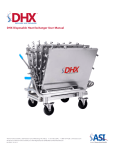
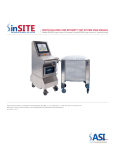
1
ASI
Life Sciences
Single-Use Filling System
User Manual
Models 4MP6000 and 4MP6001
Manual and Motorized Versions
ASI
163 Research Lane Millersburg, PA 17601
1-800-724-4158
www.asisus.com
4MP6001 Filling System
Motorized Version with Pump
Warning:
The reset sequence begins when power is supplied.
All safety precautions are the user’s responsibility.
Table of Contents
Filling System Shipping Crate
Uncrating Filling System
7
Remove the Lid
7
Remove the Sides of the Crate
8
Unbolt Filling System
9
Flatten & Store Crate9
System Setup
Removal from Shipping Crate
10
Lift Filling System to Upright Position
10
Install Handle11
Cable Connections11
Safety Notes
Failure to follow user instructions may
cause personal harm. ASI will not be
held liable for personal injury caused by
improper use of the Filling System.
• The system is designed to be
used by only one individual at a time.
• Exceeding the pressure ratings or
over filling the container will make
any warranty claims to the supplier
null and void.
• Please refer to this user manual
for proper handling and for the use
of the Filling System.
Gray Input / Output Communication Cable
11
Two Pin Twist Lock Connector
12
25 Pin Connector for Pump
12
Three Pin Twist Lock for Foot Pedal
13
Servo Motor Power Cable 13
Install Tubing into Pump
14
Install Nozzle
15
Connect your Pump
16
Filling Procedure
Position Bag on Filler Plate
17
Remove Cap for Filling
17
Engage Filling Nozzle into Connector
17
Activate Pump18
Fill Bag to Desired Level
18
Fully Close Cap
18
Remove Bag18
Warranty and Customer Service
Warranty19
Customer Service19
Additional Parts19
As e p t ic Sin g le -U s e Fillin g Sys te m Manual
3
Table of Figures
Figure
4
Description
Page
1
Filling System Crate
7
2
Unfold Cover Tabs of Crate
7
3
Flatten Cover Tabs of Crate
7
4
Removing Cover of Crate
7
5
Unfold Vertical Edge Tabs of Crate
8
6
Flatten Vertical Edge Tabs of Crate
8
7
Unfold Lower Edge Tabs of Crate
8
8
Lift Side Walls of Crate
8
9
Unscrew Base Mounting Hardware: Screwdriver
9
10
Unbolt Mounting Hardware: Crescent Wrench
9
11
Walls of Crate
9
12
Folded Walls of Crate
9
13
Folded Crate
9
14
4MP6000 Handle
10
15
4MP6000 Filling System
10
16
Pin in Shipping Position
10
17
Raise System and Re-insert Pin into Desired Position
10
18
Install Handle
11
19
Tighten Set Screws on Handle
11
20
Gray Input / Output Communication Cable
11
21
Align Notches, Insert and Twist Connector
11
22
Two Pin Twist Lock Connector
12
23
25 Pin Connector Cable to Pump
12
24
Three Pin Twist Lock Foot Pedal Cable
13
25
Servo Motor Power Cable Connection
13
26
Remove Pump Roller Lid
14
27
Install Tubing Over Rollers
14
28
Re-Install Roller Cover
14
29
Opening the Clamping Jaws
15
30
Adjustment Ridges on Clamping Jaws and Nozzle
15
31
Nozzle Clamped In-place
15
w w w. a s i s u s . c o m
Table of Figures
Figure
Description
Page
32
Pump Start Switch
16
33
Load Position of the Connector Receiver
17
34
Fill Connector in the Load Position, Ready for a Fill Cycle
17
35
Cap is Disengaged and Nozzle Tip is Moving into Position
17
36
Nozzle Fully Engaged into Fill Stem of Bag
17
37
Micro Switch in Free Position / Micro Switch Depressed
18
38
Pull Back Handle to Re-engage Cap onto Bag. Continue to Pull Back on Handle
18
39
Remove Bag
18
Table of Illustrations
Description
Page
1
Side view
20
2
Alternate Side View
20
3
Motor View
21
4
Detail View
21
5
Filling System Wiring Diagram
22
Illustration
Table of Appendices
Appendix
Description
Page
1
Preventative Maintenance
23
2
Troubleshooting Motorized Filling System
24
3
Troubleshooting Manual Filling System
25
As e p t ic Sin g le -U s e Fillin g Sys te m Manual
5
Introduction
Thank you for purchasing the 4MP6000 or
4MP6001 Filling System. In addition to the
Filling System, you will need a fluid pump and a
single-use flexible container (bag) with an ASI
interface connector. The Filling System is
available in both manual (4MP6000) and
motorized (4MP6001) versions. Both versions
include the Filling System only and do not
include the pump.
ASI has tested the fill rates and pressure ratings
with a WATSON MARLOW 620Di/L pump. Any
peristaltic pump can be used, but the user will
need to make sure that the selected pump can
be adjusted to limit the maximum pressure and
capable of reverse cycles to prevent drips.
The Filling System has been tested with a
WATSON MARLOW pump to fill pressures up
to 6 PSI with the current bag closure design and
filler nozzle.
ASI cannot guarantee the accuracy of the fill
volume as this is controlled by the pump. Please
consult the user manual provided with your
pump or consult the manufacturer regarding
volume or pressure adjustments. Operations
outside of the scope of this Filling System manual
may void the warranty. Please consult with ASI on
bag specifications.
ASI
Life Sciences
6
w w w. a s i s u s . c o m
Filling System Shipping Crate
Your new Filling System may have shipped to you in a “ULine” wooden
shipping crate (As shown in Figure 1). These wooden crates offer “vault-like”
protection for your Filling System. The crate is made of 1/4” thick plywood
and includes a 5” base pallet. After unpacking your Filling System, the crate
breaks-down for essentially flat storage and can be stored for eventual
reuse. Should you ever need to store, move or ship your Filling System, the
crate can be easily reassembled. Theses crates are export certified, allowing
your Filling System to be shipped globally.
Uncrating the Filling System
Figure 1. Filling System in a ULine shipping
crate. (Model S-13371) approximately
24” x 24” x 28 ¾” including base pallet.
To uncrate your Filling System follow these simple steps. No special tools
or skills are required. A few basic hand tools are all that is required.
•
•
•
•
A flat-blade screwdriver or small pry-bar
A small rubber mallet
Pliers or channel-locks
Crescent wrench
Step 1: Remove the Lid.
Note that the lid is secured by eight fold-over tabs. There are two along each edge of the lid. Use a flat-blade
screwdriver or similar flat prying tool to unfold the eight cover tabs. Make the tabs as flat as possible to allow the
lid to be easily removed (As shown in Figures 2 - 4).
Figure 2: Unfold the cover tabs and
bend them to vertical, as shown here
using a flat blade screwdriver.
Figure 3: Flattening the tabs with pliers
will allow the lid to lift off easily and it
facilitates the eventual reuse of the crate.
Figure 4: Removing the lid. It may
help to tap the corner of the lid to
break it free of the side wall tabs.
Then lift-off cover.
As e p t ic Sin g le -U s e Fillin g Sys te m Manual
7
Filling System Shipping Crate
Step 2: Remove the Sides of the Crate.
The walls of the crate are two pairs of side panels. Note that two vertical, opposite edges of the crate are tabbed.
Unfold and straighten the two vertical edge tabs on the vertical edge. Then, unfold and straighten the two vertical
edge tabs on the opposing vertical edge. Straightening the tabs makes is easier to separate the wall panel pairs (As
shown in Figures 5 - 6).
Figure 5: Unfold the vertical edge tabs. Shown
here using a flat blade screwdriver.
Figure 6: Flattening the tabs with channel locks will
allow the wall panel pairs to uncouple more easily and
facilitates the eventual reuse of the crate.
Note that the lower edge of each wall panel has two tabs attaching the side walls to the base pallet. These will typically
be folded under and almost unnoticeable. Locate these eight tabs, unfold them and lift the side walls away (As shown
in Figures 7-8).
Figure 7: Note that the lower edge of the wall has two
tabs. Go around the base of the crate and
unfold the eight base tabs as shown here using
a flat blade screwdriver.
8
w w w. a s i s u s . c o m
Figure 8: With all the tabs unfolded, lift away the side walls to
expose the Filling System on the bottom base pallet. Remove
any padding or protective wrap from the Filling System.
Filling System Shipping Crate
Step 3: Unbolt the Filling System from the Base Pallet
There are four mounting points on the base of the Filling System. Use the appropriate tool (Either a crescent wrench
or a screwdriver) to remove the fasteners, which secure the Filling System to the base pallet (As shown in Figure 9 - 10).
After all four fasteners are removed lift-away the Filling System.
Figure 9: Unscrew base mounting hardware
using a screwdriver.
Figure 10: Unbolt base mounting hardware using
a crescent wrench.
Step 4: Flatten and Store the Crate.
You may store the ULine crate in a relatively flat, compact fashion. Fold each of the two side wall pairs as if
closing a book. Place each pair on the base pallet. Place the cover on top of the stack (As shown in Figures 11 - 13).
Store the flattened and condensed crate in a dry location for eventual reuse.
Figure 11: Two side-wall pairs after
removal from base pallet.
Figure 12: Fold each of the pairs flat,
almost like closing a book.
Figure 13: Place the two folded side-walls
and then the lid on top of the base pallet.
As e p t ic Sin g le -U s e Fillin g Sys te m Manual
9
System Setup
Removal From Shipping Crate
Locate the following items: the handle, which is used with the manual
version (As shown in Figure 14) and Filling System (As shown in Figure 15).
Figure 14: 4MP6000 Handle.
Figure 15: 4MP6000 Filling System.
Lift Filling System to Upright Position
The Filling System is shipped in the folded-down position. Raise the system into operation position by pulling
the inclination pin, lifting the system to the desired position, and re-inserting the pin (As shown in Figure 16).
1. Pull inclination-pin from shipping position
2. Lift system to upright position
3. Place pin in desired hole dictating table angle
NOTE: ASI recommends the vertical position shown in Figure 17
(This is the last hole for inclination pin). This position supports
the best filling angle. The motorized version (4MP6001) can only
be used in this position.
Figure 16: Pin in shipping position.
10
w w w. a s i s u s . c o m
Figure 17: Pin in vertical position.
System Setup
Install the Handle on Manual Version (4MP6000):
A handle is included in both versions, but has been removed for shipping. If you have the motorized version (4MP6001),
do not install handle while the motor is connected. The handle can be attached and used (when the motor is
disconnected) if you prefer to operate the system manually.
To install: Insert the end of the handle into the hole on shaft (As shown in Figure 18). Tighten set screws on both sides
using 1/8” Allen wrench (As shown in Figure 19). Allen wrench not included.
NOTE: There are two handle orientation options to choose
from. To change the handle orientation, remove the one
Allen-head set screw from the receiver on the end of the
shaft. You may move the handle to a desired position to
ease the filler operation. Pivot the handle up or down to
preferred orientation and tighten the three Allen screws.
Figure 18: Install handle.
Cable Connections: Gray Input / Output Communication Cable
To set up the Filling System and the pump, first locate the gray input / output
communication cable used to connect the pump to the motor (As shown in Figure 20)
Note the notch located on the cable’s end and motor connector. Align the notches and
insert the gray input / output cable into the motor. Then twist the connector until it is
firmly seated in place (As shown in Figure 21).
Figure 20: Gray input / output
communication cable.
Figure 19: Tighten set
screw on handle.
Instructional Video
Figure 21: Align notches, insert cable and twist the connector until firmly in place.
As e p t ic Sin g le -U s e Fillin g Sys te m Manual
11
System Setup
Cable Connections: Two Pin Twist Lock Connector
Locate and connect the two pin twist lock connector for the pump start switch. Connect the two ends. Then twist to lock
the connection (As shown in Figure 22).
Figure 22: Locate the two pin twist lock connector. Twist to lock the connection.
Cable Connections: 25 Pin Connector for the 620Di/L Watson Marlow Pump
Locate the 25 pin connector for the 620 Di/L Watson Marlow pump and plug it into the back of the pump. Then
twist the screws to tighten the cable to the pump (As shown in Figure 23).
Figure 23: Locate the 25 pin connector and twist the screws to tighten the cable to pump.
12
w w w. a s i s u s . c o m
System Setup
Cable Connections: Three Pin Twist Lock Connector for the Foot Pedal
Locate the three pin twist lock connector for the foot pedal. Plug the ends together and twist to secure the
connection (As shown in Figure 24).
Figure 24: Locate the three pin twist lock and plug and test to secure connection.
Cable Connections: Servo Motor Power Cable
Connect the power cable to the servo motor by inserting it into the power input and twist the connector until firmly
seated in place (As shown in Figure 25).
Figure 25: Locate the servo motor power cable, insert into power input and twist in place.
NOTE: DO NOT PLUG IN THE
POWER CABLE INTO A WALL
RECEPTACLE AT THIS TIME.
As e p t ic Sin g le -U s e Fillin g Sys te m Manual
13
System Setup
Installing Tubing into the Pump
To install the pump tubing, first remove the pump roller cover (As shown in Figure 26). Next, install the pump tubing over
the rollers and stretch to the retention pin (As shown in Figure 27). Now, Re-install the roller cover (As shown in Figure 28).
NOTE: See the Watson Marlow pump setup guide for more information.
Figure 26: Remove the pump roller cover.
Figure 27: Install tubing over the rollers and stretch to the retention pin.
Figure 28: Re-install the roller cover.
14
w w w. a s i s u s . c o m
System Setup
Install Nozzle
To install the nozzle assembly, open the clamp collar on the Filling System by turning the adjustment nut towards
you (As shown in Figure 29). Note the adjustment ridges in the clamping jaws and nozzle (As shown in Figure 30).
Figure 29: Opening the clamping jaws.
Figure 30: Adjustment ridges on the clamping jaws and nozzle.
Place nozzle into the collar, engaging the slot of the nozzle with the ridges in the clamping jaws. Tighten clamping
collar by turning adjustment nut away from you. This will secure the nozzle (As shown in Figure 31).
Figure 31: Nozzle clamped in-place and twist clamping collar to secure nozzle.
As e p t ic Sin g le -U s e Fillin g Sys te m Manual
15
System Setup
Connect your Pump
A pump is not included with the Filling System. ASI recommends
the use of a 620Di/L WATSON MARLOW pump. Any peristaltic
pump can be used, but the user will need to make sure that the
selected pump can be adjusted to limit the maximum pressure
and capable of reverse cycles to prevent drips.
www.watson-marlow.com
Plug the end of the Micro Start switch cord (As shown in Figure 32) into the supplied main cable. The Micro Start
switch is shown on the right side of Figure 32. When the switch is depressed the internal contacts will be closed. The
switch is depressed (contacts closed) when the nozzle is engaged with connector in the fill position.
The user must select a pump and qualify the volumetric pump to be used in concert with the Filling System. The
Micro Start switch will activate the “pump start” of any pump of choice. There is an adjustment for the Micro Start
switch for making contact. The Filling System has been tested with a WATSON MARLOW pump at fill pressures up to
6 PSI with the current bag closure design and Filling System nozzle.
Figure 32: Micro Start Switch.
16
w w w. a s i s u s . c o m
Filling Procedure
Position Bag for a Fill
To fill a new bag, first verify that you have the
correct pump settings for the bag volume you will
fill. Connector retainer and cap gripper has to be
in the load (stand by) position (As shown in Figure
33). Insert the connector flange into the connector
retainer. The cap gripper needs to be engaged
under the cap (As shown in Figure 34).
Figure 33: Load position of the
connector retainer.
Figure 34: Fill connector in the
load position, ready for fill cycle.
Remove Cap for Filling
If you are using the manual Filling System (4MP6000), remove
the cap by pushing the handle forward to disengage the cap
from the connector body (As shown in Figure 35). For the
motorized version (4MP6001), depress the foot pedal actuator
and the cap will be removed from the connector body. The
cap is opened and ready for filling.
Figure 35: Cap is disengaged and
nozzle tip is moving into position.
Engage the Filling Nozzle into Connector
In the case of the manual Filling System (4MP6000), continue to
push handle forward to complete the docking of the nozzle into
the fill connector of the bag (As shown in Figure 36). If you have
a motorized version this will occur automatically. The Motorized
Filling System (4MP6001) takes care of all necessary alignments,
positioning and engagement.
Figure 36: Nozzle fully engaged
into fill stem of bag.
As e p t ic Sin g le -U s e Fillin g Sys te m Manual
17
Filling Procedure
Activate Pump
When the nozzle is fully engaged, the micro switch will be
depressed, activating your pump. The motorized version (4MP6001)
will do this automatically (As shown in Figure 37).
Figure 37: Micro Switch in free position, switch contacts
open. Micro Switch depressed, contacts closed.
Fill Bag to Desired Level
Your volumetric pump, when setup properly, will stop filling
automatically when the set level is reached.
Fully Close Cap
Now that the bag is filled, the cap must be re-seated and locked
onto the connector body. Pull back on the handle of the manual
version Filling System until the cap engages the connector and
engages to the fully closed position (As shown in Figure 38). The
motorized version (4MP6001) will do this automatically for you.
Figure 38: Pull back handle to re-engage cap onto
bag. Continue to pull back on handle until cap is
engaged into the fully closed and sealed position.
Note: The bag is now sealed and tamper resistant. Once the cap
is locked, it cannot be refilled, nor can its contents be altered.
Remove Bag
Remove the bag and store appropriately (As shown in Figure 39).
You may fill another bag of the same specification. If you wish
to fill a different bag specification, adjust your pump to the
new volume.
Figure 39: Remove Bag.
18
w w w. a s i s u s . c o m
Warranty and Customer Service
Warranty
The product warranty includes part replacement for worn and broken components.
The warranty excludes any physical damage, abuse or improper use of the Filling System.
The warranty applies for six (6) months from the date of purchase.
When contacting Customer Service Representatives; please have your serial
number ready. The serial number is located on the bottom of the base.
Customer Service
ASI
163 Research Lane
Millersburg, PA 17061
717-692-2104 | 1-8 0 0 - 7 2 4 - 4 1 5 8
www.asisus.com
Additional Parts
Should you require additional parts for your Filling System, please refer to the
part numbers listed.
Part Number
Description
6025 ........................
6065 ........................
C05 ..........................
6070 ........................
Nozzle replacement assembly
Ram carriage assembly
Micro switch
Nozzle replacement kit
System Repair Parts Kit
C16 ........................
C01 ........................
C14 ........................
C17 ........................
C10 ........................
Disc spring set / 4 pieces
Cam track roller
End position plunger
Home position spring
Gripper spring
As e p t ic Sin g le -U s e Fillin g Sys te m Manual
19
Illustrations
WASHER
Illustration 1. Side View
Item Number
Part Number
Description
1
6001-1
Frame Base
2
6031-1
Table
3
6022-1
Handle Base
4
C05
Micro Switch
DETAIL A
4
3
1
2
Illustration 2. Alternate Side View.
Item Number
Part Number
Description
5
5013-1
Cap Gripper and
Plunger Assembly
6
6024-1
Nozzle Clamp
7
6027-1
Connector Retainer
5
6
7
20
w w w. a s i s u s . c o m
DETAIL B
Illustrations
10
Illustration 3. Motor View
Item Number
Part Number
Description
8
6064-1 - 6066-1
Motor Bracket Assembly
9
MD34AC
Motor
10
6067-1
Coupling
9
8
Illustration 4. Detail View
Item Number
Part Number
Description
11
C16
Disc Spring Set
WASHER
11
WASHER
As e p t ic Sin g le -U s e Fillin g Sys te m Manual
21
Illustrations
Illustration 5. Filling System Wiring Diagram
IMS MOTOR PLUG
PINK I/O #4
FOOT PEDAL
START CYCLE
FP1
JUNCTION BOX
GREEN (GROUND)
WHITE
BLACK
PUMP START
DOSE CYCLE
GREEN/YELLOW (GROUND)
WHITE/GRAY I/O
BLUE/RED
BLACK
WHITE
SW1
WATSON MARLOW
CONNECTOR DP25 PIN
PUMP START
DOSE CYCLE
PIN #8
PIN #9
PIN #14
PIN #11
22
w w w. a s i s u s . c o m
WHITE
BLACK
I/O GROUND WHITE/GRAY
RED I/O CYCLE COMPLETE
Appendix 1
General Cleaning
Using Isopropyl or Denatured alcohol, spray and wipe all parts of 4MP6000 /
4MP6001.
Preventative Maintenance
Suggested every 10,000 cycles or it problem occurs
1. Inspect Filling System for any loose components. Be sure to check:
a. Nozzle brackets.
b. Cap stripper assembly.
c. Moving linkage.
2. Tighten all hardware for proper system operation.
a. Check nozzle bracket.
b. Check stripper bracket.
c. Set screws on couplers and moving linkage.
3. When cap cover is removed for cleaning, count the number of ball
bearings in the slide assembly.
a. There should be 48 ball bearings per liner. Replacement ball bearings can
be installed into the cover and liner assembly.
As e p t ic Sin g le -U s e Fillin g Sys te m Manual
23
Appendix 2
Trouble Shooting Motorized Filling System
1. Cap will not load into receiver:
a. Filler is not in load stand by position.
b. Loose hardware or linkage - Check set screws and key on drive shafts.
c. Check cap stripper linkage and arm.
d. Motorized Filling System is not homed - Cycle power to reset home and
load position.
2. Nozzle will not compress to fill connector:
a. Nozzle is not installed in nozzle retaining bracket locator.
b. Check nozzle arm set screw and key way at nozzle linkage.
c. Check ball detents for nozzle linkage lock. Adjust 1/8 turn and cycle the Filling System.
3. Nozzle misalignment:
a. Adjust plastic nozzle to properly align with connector body.
b. Check guide track for full travel of bag plate.
c. Connector body not seated in receiver.
d. Check the ball detents in receiver to hold connector body in place.
4. Pump is not cycling:
a. Check the pump fill switch connection.
b. Check nozzle bracket engagement of the ball start switch.
c. Check the pump dose and setup status.
d. Nozzle shutoff is not opening when inserted into connector body. This is due
to improper nozzle installation.
5. System not cycling:
24
w w w. a s i s u s . c o m
a. Check the power supply.
b. Check all of the electrical and communication connections.
c. Cycle power to reset home and load position.
d. If home cycle completes upon power up, check foot pedal connection.
e. If cycle begins, but does not fill, check ball start switch for pump. If pump
cycles and the system does not complete cycle, check signal from pump to the system.
Appendix 3
Trouble Shooting Manual Filling System
1. Cap will not load into receiver:
a. Filler is not in load position.
b. Loose hardware or linkage - Check set screws and key on drive shafts.
c. Check cap stripper linkage and arm.
2. Nozzle will not compress to fill connector:
a. Nozzle is not installed in nozzle retaining bracket locator.
b. Check nozzle set screw and key way at nozzle linkage.
c. Check ball detents for nozzle linkage lock. Adjust 1/8 turn
and cycle the Filling System.
3. Nozzle misalignment:
a. Adjust the plastic nozzle to properly align with connector body.
b. Check the guide track for full travel of bag plate.
c. Connector body not seated in receiver.
d. Check the ball detents in receiver to hold connector body in place.
4. Pump is not cycling:
a. Check the pump fill switch connection.
b. Check the nozzle bracket engagement of ball start switch.
c. Check the pump dose and setup status.
d. Nozzle shutoff is not opening when inserted into connector body. This is
due to improper nozzle installation.
If any additional trouble shooting assistance is required,
please call Customer Service: 1-800-724-4158
As e p t ic Sin g le -U s e Fillin g Sys te m Manual
25
Instructional Video
ASI
Life Sciences
ASI | 163 Research Lane, Millersburg, PA | (717) 692-2104 | (800) 724-4158 | www.asisus.com
ASI is an FDA Registered, ISO 13485:2003 Certified Manufacturer
PK-01317 REV F | 12-31-12
ASI
Life Sciences
ASI ASEPTIC SINGLE-USE FILLING SYSTEM
ASI's Filling System, when used in conjunction with good technique
and a laminar flow hood, yields an aseptic bag fill. The filling system
utilizes a fixture and cap assembly developed and manufactured by
ASI and fully controls the filling interface with no user interaction
required with the fill port. What is left after completion is a tamper
evident dispensing port. This results in a cleaner, more efficient and
cost effective method of filling.
ASI Catalog #
Description
4MP6000
Manual Filling System
4MP6001
Semi-Automatic Filling System
B100787-I
1 Liter Bag with Fill Connector (3,000 count)
N/A
Watson Marlow 620Di/L Peristaltic Pump
4MP6065
Ram Carriage Assembly
Port 1: Co-Ex Tube ASI Filling Connector
P1
Port 1: Co-Ex Tube ASI Filling Connector
Port 2: 1/8” ID x 1/4” OD Clear C-Flex 374 (16”)
LL Female + Cap, Slide Clamp
P1
P2
ASI | 163 Research Lane, Millersburg, PA | (717) 692-2104 | (800) 724-4158 | www.asisus.com
ASI is an FDA Registered, ISO 13485:2003 Certified Manufacturer
Rev 01-16-13
MK-00044
ASI Catalog #
Size
B100783-I
50 mL
B100784-I
100 mL
B100785-I
250 mL
B100786-I
500 mL
B100787-I
1 Liter
ASI Catalog #
Size
B100788-I
50 mL
B100789-I
100 mL
B100790-I
250 mL
B100791-I
500 mL
B100792-I
1 Liter