1
Heating Immersion Circulators
Cooling/Heating Circulating Baths
Heating Circulating Baths
Manual P/N U01165 Rev. 10/18/2012
User's Manual
Table of Contents
Quick Starts
Preface
....................................................................................................................... i
Compliance...............................................................................................................i
Warranty....................................................................................................................i
Unpacking.................................................................................................................i
Section 1 Safety...................................................................................1-1
Safety Warnings...................................................................................................1-1
Section 2 General Information. ...............................................................2-1
Description..........................................................................................................2-1
Intended Use.......................................................................................................2-1
Sample Nameplate . ...........................................................................................2-1
Equipment Ratings.............................................................................................2-1
Specifications.......................................................................................................2-2
Wetted Parts.........................................................................................................2-7
Section 3 Installation............................................................................3-1
Immersion Circulator Only...............................................................................3-1
Circulating Baths.................................................................................................3-2
Ventilation............................................................................................................3-2
Electrical Requirements.....................................................................................3-2
Remote Temperature Sensor.............................................................................3-4
External Circulation...........................................................................................3-5
Approved Fluids.................................................................................................3-5
Additional Fluid Precautions............................................................................3-8
Filling Requirements .........................................................................................3-8
Draining................................................................................................................3-8
Section 4 Operation . ............................................................................4-1
Controller.............................................................................................................4-1
Setup.....................................................................................................................4-2
Start Up................................................................................................................4-2
Status Display......................................................................................................4-3
Standby Mode......................................................................................................4-3
Changing the Setpoint........................................................................................4-4
Menu Displays.....................................................................................................4-5
Menu.....................................................................................................................4-5
Menu Tree............................................................................................................4-6
Settings.................................................................................................................4-7
High Temperature Cutout...............................................................................4-15
Stopping the Circulator....................................................................................4-16
Cole Parmer
Contents
Power Down......................................................................................................4-16
Shut Down.........................................................................................................4-16
Restarting...........................................................................................................4-16
Section 5 Preventive Maintenance. .........................................................5-1
Cleaning ............................................................................................................5-1
CondenserFins...................................................................................................5-1
Testing the Safety Features................................................................................5-2
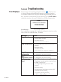
Section 6 Troubleshooting................................................................................................ 6-1
Error Displays.....................................................................................................6-1
Check List............................................................................................................6-3
Appendix
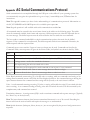
AC Serial Communications Protocol................................................................1
Declaration of Conformity
RoHS Declaration of Conformity
Cole Parmer
Appropriate size clamps or connection type
Appropriate hose or plumbing
An adjustable wrench
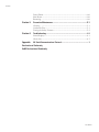
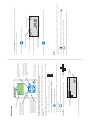
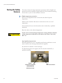
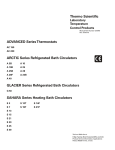
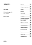
What you need to get started:
Immersion Circulator 12120-13
Return Flow
Remote
Temperature
Sensor
Outlet Flow
Line cord connection
I/O Circuit
Protector
Ensure the electrical cords do not come in contact with any of the plumbing connections or tubing.
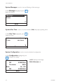
7KHSOXPELQJFRQQHFWLRQVIRUH[WHUQDOFLUFXODWLRQDUHORFDWHGRQWKHUHDURI WKHFRQWUROOHU
LVWKHUHWXUQ
LVWKHRXWOHWÁRZWRWKHH[WHUQDODSSOLFDWLRQVXSSO\VLGH7KHFRQQHFWLRQV
ÁRZIURPWKHH[WHUQDODSSOLFDWLRQ
DUHPP2'5HPRYHWKHXQLRQQXWVDQGSODWHVWRLQVWDOOWKHPPRUPPKRVHEDUEVDQGFODPSVVXSSOLHG
ZLWKWKHXQLW
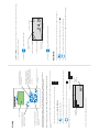
Outlet Flow
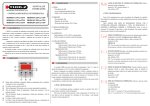
USB
Connection
Return Flow
Line cord from bath
Cable connection
required for proper
communication between
the cooling/heating
bath and the circulator.
Communications cable
from cooling/heating bath
)RUDOOEDWKVHQVXUHWKHFRPPXQLFDWLRQVFDEOHIURPWKHEDWKLVFRQQHFWHGWRWKH5-FRQQHFWRUVVLPLODUWR
(WKHUQHWRQWKHUHDURI WKHFRQWUROOHU
)RUFRROLQJKHDWLQJEDWKVHQVXUHWKHOLQHFRUGIURPWKHEDWKLVVHFXUHO\FRQQHFWHGWRWKHUHDURI WKH
FRQWUROOHU
Ensure all communication and electrical connections are made prior to starting the unit.
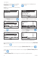
%HIRUHXVLQJDQ\ÀXLGRUSHUIRUPLQJPDLQWHQDQFHZKHUHFRQWDFWZLWKWKH
ÀXLGLVOLNHO\UHIHUWRWKHPDQXIDFWXUHU¶V06'6IRUKDQGOLQJSUHFDXWLRQV
Ensure the tubing you select will meet your maximum temperature and
pressure requirements.
1HYHUXVHÀDPPDEOHRUFRUURVLYHÀXLGVZLWKWKLVXQLW
Never place unit in a location where excessive heat, moisture, inadequate
ventilation, or corrosive materials are present.
The unit is designed for indoor use only.
Safety Precautions:
Acceptable Fluids:
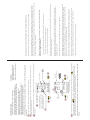
0RQLWRUWKHÁXLGOHYHOZKHQHYHUKHDWLQJWKHÁXLG
:KHQSXPSLQJWRDQH[WHUQDOV\VWHPNHHSH[WUDÁXLGRQKDQGWRPDLQWDLQWKHSURSHUOHYHOLQWKHFLUFXODWLQJOLQHV
DQGWKHH[WHUQDOV\VWHP
$YRLGRYHUÀOOLQJRLOEDVHGÁXLGVH[SDQGZKHQKHDWHG
:LWKDORZOHYHO:$51,1*WKHXQLWFRQWLQXHVWRUXQZLWKD)$8/7WKHXQLWZLOOVKXWWKHUHIULJHUDWLRQSXPSDQG
KHDWHUZLOOVKXWGRZQVHHPDQXDO7KHORZOHYHOZDUQLQJLVDWDSSUR[LPDWHO\FPµEHORZWKHWRSWKHORZ
OHYHOIDXOWLVDWDSSUR[LPDWHO\FPµ
7RDYRLGVSLOOLQJSODFH\RXUFRQWDLQHUVLQWRWKHEDWKEHIRUHÀOOLQJ
(QVXUHWKHUHVHUYRLUGUDLQSRUWRQWKHIURQWRI WKHXQLWLVclosedDQGWKDWDOOSOXPELQJFRQQHFWLRQVDUHVHFXUH$OVR
HQVXUHDQ\UHVLGXHLVWKRURXJKO\UHPRYHGEHIRUHÀOOLQJWKHXQLW
:KHQXVLQJWKHLQWHUQDOEDWKRQO\WKHSOXPELQJFRQQHFWLRQVFDQEHFORVHGZLWKWKHVXSSOLHGSODWHDQGXQLRQQXWV
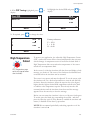
VHFXUHDOOWXEHFRQQHFWLRQVXVLQJFODPSV
WXEHVPXVWQRWEHIROGHGRUEHQW
WKHUHTXLUHGWXEHPDWHULDOGHSHQGVRQWKHKHDWWUDQVIHUOLTXLGXVHG
Extreme operating temperatures will lead to extreme temperatures on the tube surface, this is even more
critical with metal nozzles.
7KHPD[LPXPDOORZDEOHOHQJWKRI WXEHGHSHQGVODUJHO\RQWKHVL]HIRUPDQGPDWHULDORI WKHH[WHUQDOYHVVHO7KH
OHQJWKRI WXEHDQGLWVGLDPHWHUFRPELQHGZLWKWKHFLUFXODWLQJFDSDFLW\KDYHDODUJHHIIHFWRQWKHWHPSHUDWXUH
VWDELOLW\:KHQHYHUSRVVLEOHXVHDZLGHUWXEHGLDPHWHUDQGSODFHWKHDSSOLFDWLRQDVFORVHDVSRVVLEOHWRWKHFLUFXODWRU
7XELQJLVQRUPDOO\XVHGWRFRQQHFWWKHSXPSWRDQH[WHUQDODSSOLFDWLRQ
Ensure none of the tubing comes in contact with the power cord.
SIL 100, SIL 180, SIL 200, SIL 300
SYNTH 60, SYNTH 200, SYNTH 260
-40°C to 200°C — SIL180
-30°C to 80°C — Water with Glycol
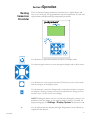
5°C to 95°C — Distilled Water or Deionized WaterXSWR0ƙFP
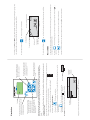
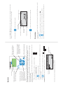
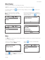
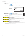
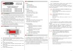
Display Screen
Use this button to place the unit in and
out of standby.
Use this button to cancel any changes
and to return the controller to its
previous display. Canceling a change
can only be made before the change is
saved. In some cases, it is also used to
save changes.
Use these four navigation arrows to
move through the controller displays
and to adjust values.
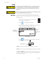
WKH6WDUW'LVSOD\ZLOODSSHDU
O
I
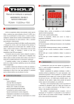
Start Display
$IWHUVWDUWFKHFNDOOH[WHUQDOSOXPELQJFRQQHFWLRQVIRUOHDNV
Highlighted
Start Symbol
SP1
20.0
24.2°C
Menu
Stop Symbol
7KHXQLWZLOOVWDUWDQGWKHVWDUWV\PEROZLOOWXUQLQWRDVWRSV\PERO
NOTE ,WZLOOWDNHVHFRQGVIRUWKHFRPSUHVVRUWRVWDUW
3UHVV
Reservoir
Fluid
Temperature
20.0
(QVXUHWKHVWDUWV\PEROKDVDKLJKOLJKWER[DURXQGLWLI QRWXVHWKHDUURZNH\VWRQDYLJDWHWRWKHV\PERO
3UHVV
7KHFRQWUROOHUZLOOGLVSOD\System Standby
3ODFHWKHFLUFXLWSURWHFWRUORFDWHGRQWKHUHDURI WKHXQLWWRWKHISRVLWLRQ
RQRWUXQWKHXQLWXQWLOÁXLGLVDGGHGWRWKHXQLW+DYHH[WUDÁXLGRQKDQG,I WKHXQLWZLOOQRWVWDUWUHIHUWRWKH
'
PDQXDO
Before starting the unit, double check all USB (optional), electrical and plumbing connections.
Cooling/heating units should be left in an upright position at room temperature (~25°C) for 24 hours
before starting. This will ensure the lubrication oil has drained back into the compressor.
Use this button to start/stop the unit.
This button is also used to make
and save changes on the controller's
display screen.
Use the adjacent dial for adjusting the
High Temperature Cutout. Details are
explained in the manual.
Start Up
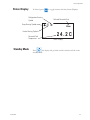
Refrigeration Running
Symbol
WREULQJXSWKH6WDWXV'LVSOD\V
WRWRJJOHEHWZHHQWKH6WDUW6WDWXV'LVSOD\V
Status Display
24.2C
Water
Selected Reservoir Fluid
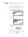
7KHFLUFXODWRU·VVFUHHQZLOOJREODQNDQGWKHEOXH/('ZLOOLOOXPLQDWH
3UHVV
3ODFHWKHFLUFXLWSURWHFWRURQWKHUHDURI WKHWKHUPRVWDWWRWKHOSRVLWLRQ7KHEOXH/('ZLOOH[WLQJXLVK
7KHXQLWZLOOVWRSDQGWKHVWRSV\PEROZLOOWXUQLQWRDVWDUWV\PERO
3UHVV
(QVXUHWKHVWRSV\PEROKDVDER[DURXQGLWLI QRWXVHWKHDUURZNH\VWRQDYLJDWHWRWKHV\PERO
Shut Dowm
,I GHVLUHGSUHVV
Reservoir Fluid
Temperature
Heater Running Symbol
Pump Running Symbol
,I GHVLUHGSUHVV
7KHSP1DQGMenuSRUWLRQVRQWKHWRSRI WKHGLVSOD\DUHXVHGWRYLHZDQGRUFKDQJHWKHFRQWUROOHU
VVHWWLQJV
7KH\DUHH[SODLQHGLQGHWDLOLQWKHPDQXDO
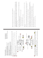
Geeignete Flüssigkeiten:
12120-13 Eintauchthermostat
5FNÀXVV
TemperaturFernsteuersensor
$EÀXVV
Netzanschlussbuchse
E/A-Netzschalter
Achten Sie darauf, dass die Stromkabel nicht mit einem der Wasseranschlüsse oder Schläuche in Kontakt
geraten.
'LH6FKODXFKDQVFKOVVHIUGHQH[WHUQHQ8PODXI EHÀQGHQVLFKDXI GHU5HJOHUUFNVHLWH
LVWGHU5FNÁXVV
LVWGHU$EÁXVVLQ5LFKWXQJGHUH[WHUQHQ$QZHQGXQJ=XÁXVVVHLWH'HU
von der externen Anwendung.
Außendurchmesser der Anschlüsse beträgt 16 mm. Entfernen Sie die Überwurfmuttern und Platten, um die mit
dem Gerät mitgelieferten 8 mm bzw. 12 mm Schlauchtüllen und -klemmen zu montieren.
$EÀXVV
USBSchnittstelle
5FNÀXVV
Buchse für Netzkabel vom Bad
Zur ordnungsgemäßen Kommunikation zwischen dem gekühlten Bad
und dem Umwälzthermostat ist eine
Kabelverbindung erforderlich.
Kommunikationskabel
vom gekühlten Bad
Schließen Sie das mitgelieferte Netzkabel an den Regler an und stecken Sie es in eine ordnungsgemäß geerdete
Wandsteckdose.
Das Kommunikationskabel vom Bad muss am RJ45-Anschluss (ähnelt einem Ethernet-Anschluss) an der
Reglerrückseite angeschlossen sein.
Das Netzkabel vom Bad muss sicher an der Reglerrückseite befestigt sein.
Vor der Inbetriebnahme des Geräts müssen alle Kommunikations- und Stromverbindungen hergestellt
worden sein.
Bevor Sie Flüssigkeiten einsetzen oder eine Wartung durchführen, bei denen Sie
möglicherweise mit Flüssigkeiten in Berührung kommen, beachten Sie die im
Sicherheitsdatenblatt des Herstellers beschriebenen Vorsichtsmaßnahmen.
Überwachen Sie den Füllstand sorgfältig beim Erhitzen der Flüssigkeit.
Kurzanleitung Art.-Nr. U01120
Ausg. 08/29/11
Halten Sie zusätzliche Flüssigkeit griffbereit, wenn Sie Flüssigkeit in ein externes System pumpen, um den
ordnungsgemäßen Füllstand in den Umwälzleitungen und im externen System aufrecht zu erhalten.
Vermeiden Sie ein Überfüllen, da sich Flüssigkeiten auf Ölbasis unter Erwärmung ausdehnen.
Wenn eine Warnmeldung auf einen niedrigen Füllstand hinweist, läuft das Gerät trotzdem weiter; bei einem Fehler
schaltet es Kühlung, Pumpe und Heizung ab (siehe Gebrauchsanweisung). Die Warnmeldung zum niedrigen
Füllstand erscheint, wenn der Flüssigkeitsspiegel ca. 4 cm unterhalb des oberen Randes liegt; ein Fehler wird
generiert, wenn er ca. 5,5 cm unterhalb des oberen Randes liegt.
Stellen Sie die Behälter vor dem Befüllen in das Bad, um ein Überlaufen zu vermeiden.
Achten Sie darauf, dass der Ablaufhahn des Behälters an der Vorderseite des Geräts geschlossen ist und alle
Wasseranschlüsse fest sitzen. Achten Sie außerdem darauf, dass vor dem Befüllen des Geräts alle Rückstände
gründlich entfernt wurden.
Wenn nur das interne Bad verwendet wird, können die Wasseranschlüsse mithilfe der mitgelieferten Platte und den
Überwurfmuttern geschlossen werden.
sichern Sie alle Schlauchanschlüsse mit Schlauchklemmen
die Schläuche dürfen nicht geknickt oder gebogen werden
GDVHUIRUGHUOLFKH6FKODXFKPDWHULDOKlQJWYRQGHUYHUZHQGHWHQ:lUPHWUlJHUÁVVLJNHLWDE
([WUHPH%HWULHEVWHPSHUDWXUHQIKUHQ]XH[WUHPHQ7HPSHUDWXUHQDQGHU6FKODXFKREHUÁlFKH
insbesondere bei Metallschläuchen.
Die maximal zulässige Schlauchlänge des Rohres hängt weitgehend von Größe, Form und Material des äußeren
*HIlHVDE6FKODXFKOlQJHXQGGXUFKPHVVHUVRZLHGLH8PZlO]OHLVWXQJKDEHQHLQHQVWDUNHQ(LQÁXVVDXI GLH
Temperaturkonstanz. Verwenden Sie möglichst einen größeren Schlauchdurchmesser und stellen Sie die Anwendung
so nahe wie möglich an den Umwälzthermostat.
Schläuche dienen normalerweise dazu, die Pumpe an eine externe Anwendung anzuschließen.
Achten Sie darauf, dass keiner der Schläuche mit dem Stromkabel in Kontakt gerät.
SYNTH 60, SYNTH 200, SYNTH 260
-40°C bis 200°C — SIL180
5 °C bis 95 °C — destilliertes oder deionisiertes Wasser
ELV]X0ƙFP
-30 °C bis 80 °C — Wasser mit Glykol
Stellen Sie sicher, dass die von Ihnen ausgewählten Schläuche die
Höchstgrenzen für Temperatur und Druck nicht überschreiten.
passende Klemmen oder Anschlussstücke
passende Schläuche bzw. Leitungen
einen verstellbaren Schraubenschlüssel
Sie benötigen:
Verwenden Sie niemals brennbare oder korrosive Flüssigkeiten in diesem Gerät.
Stellen Sie das Gerät niemals an Orten auf, wo es übermäßiger Hitze,
Feuchtigkeit, unzureichender Belüftung oder korrosiven Stoffen ausgesetzt ist.
Das Gerät darf nur in geschlossenen Räumen betrieben werden.
Sicherheitsvorkehrungen:
Display
Mit dieser Taste kann das Gerät in und
aus dem Standby-Modus geschaltet
werden.
Ein- und Ausschalten des Geräts. Diese
Taste dient darüber hinaus zum Vornehmen und Speichern von Änderungen an Reglerparametern.
Mit diesen vier Navigationspfeiltasten
können Sie durch die Regleranzeigen
blättern und Werte einstellen.
. Die Startanzeige erscheint.
O
Startanzeige
24.2°C
Menü
Stopp-Symbol
Überprüfen Sie nach dem Start alle externen Schlauchanschlüsse auf Dichtheit.
Markiertes
Startsymbol
SP1
20.0
HINWEIS Es dauert 30 Sekunden, bis der Kompressor anläuft.
. Das Gerät wird gestartet, und statt dem
'UFNHQ6LH
) angezeigt.
Startsymbol wird jetzt das Stoppsymbol (
Flüssigkeitstemperatur
im Behälter
20.0
'DV6WDUWV\PEROPXVVKHUYRUJHKREHQVHLQ*HKHQ6LHPLWGHQ3IHLOWDVWHQ]XGLHVHP6\PEROZHQQGLHV
nicht der Fall ist.
'UFNHQ6LHDXI
Der Regler zeigt System Standby an.
6FKDOWHQ6LHGHQ1HW]VFKDOWHUDXI GHU*HUlWHUFNVHLWHLQGLH6WHOOXQJI.
Das Gerät niemals mit leerem Behälter betreiben. Halten Sie zusätzliche Flüssigkeit griffbereit. Konsultieren Sie die
Gebrauchsanweisung, wenn sich das Gerät nicht einschaltet.
I
I nspizieren Sie vor dem Einschalten alle elektrischen Anschlüsse, Schlauchverbindungen und (optional)
USB-Kabelanschlüsse.
Gekühlte Geräte müssen vor dem Einschalten mindestens 24 Stunden lang bei ~25°C in aufrechter
Position gestanden haben. Dadurch wird gewährleistet, dass das Schmieröl zurück in den Kompressor
ÁLHW
Mit dieser Taste können Sie vorgenommene Änderungen verwerfen und zum
vorherigen Bildschirm zurückkehren.
Eine Änderung kann nur verworfen
werden, wenn sie noch nicht gespeichert wurde. In manchen Fällen wird
diese Taste auch zum Speichern einer
Änderung verwendet.
Mit Hilfe der nebenstehenden Skala können Sie
den Übertemperaturschutz einstellen. Ausführliche Informationen finden Sie
in der Gebrauchsanweisung.
Einschalten
, um zwischen der Startanzeige und den Statusanzeigen umzuschalten.
Statusanzeige
24.2C
Wasser
. Das Display des Thermostats schaltet sich aus und die blaue LED leuchtet.
. Das Gerät wird gestoppt, und statt dem Stoppsymbol wird jetzt das Startsymbol (
Schalten Sie den Netzschalter auf der Thermostatrückseite in die Stellung O. Die blaue LED erlischt.
Drücken Sie
Drücken Sie
angezeigt.
)
Achten Sie darauf, dass das Stopp-Symbol in einem Kästchen erscheint. Navigieren Sie mit den Pfeiltasten auf
das Symbol, wenn dies nicht der Fall ist.
Ausschalten
Drücken Sie bei Bedarf auf
Flüssigkeitstemperatur
im Behälter
Heizlaufsymbol
Pumpenlaufsymbol
,P%HKlOWHUEH¿QGOLFKH)OVVLJNHLW
, um die Statusanzeigen einzublenden.
Kühllaufsymbol
Drücken Sie bei Bedarf auf
Über die Optionen SP1 und Menü am oberen Bildschirmrand können die Reglereinstellungen angezeigt und/
oder geändert werden. Sie werden ausführlich in der Gebrauchsanweisung erläutert.
FROOLHUVRXUDFFRUGVGHWDLOOHDSSURSULpH
ÀH[LEOHHWPDWpULHOGHSORPEHULHDSSURSULp
clé à molette
Matériel requis :
Circulateur à immersion 12120-13
Retour de débit
"retour application"
Capteur de
température à
distance
Sortie de débit "vers application"
Connecteur du câble
d'alimentation
Protection de
circuit I/O
/HVUDFFRUGVGHSORPEHULHSRXUODFLUFXODWLRQH[WHUQHVHVLWXHQWjO
DUULqUHGXFRQWU{OHXU
HVWODFRQQH[LRQ
HVWODFRQQH[LRQGHVRUWLHYHUVO
DSSOLFDWLRQH[WHUQHF{WpDOLPHQWDWLRQ
GHUHWRXUGHO
DSSOLFDWLRQH[WHUQH
/HVFRQQHFWHXUVPHVXUHQWPPGHGLDPqWUHH[WpULHXU(QOHYHUOHVpFURXVXQLRQVHWOHVSODTXHVSRXULQVWDOOHUOHV
UDFFRUGVFDQQHOpVGHRXPPHWOHVFROOLHUVIRXUQLVDYHFO
DSSDUHLO
Veiller à ce que les cordons électriques ne touchent pas les raccords de plomberie ou la tubulure.
Sortie de débit
"vers application"
Connecteur
USB
Retour de débit
"retour application"
Câble d'alimentation
partant du bain
Connecteur pour câble de
connexion indispensable pour
la communication entre le bain
réfrigéré et le circulateur.
Câble de communications
partant du bain réfrigéré
%UDQFKHUOHFRUGRQG
DOLPHQWDWLRQIRXUQLHQWUHOHFRQWU{OHXUHWXQHSULVHGHFRXUDQWDYHFXQHSULVHGHWHUUH
6
DVVXUHUTXHOHFkEOHGHFRPPXQLFDWLRQSDUWDQWGXEDLQHVWEUDQFKpVXUOHVFRQQHFWHXUV5-VLPLODLUHVjGHV
FRQQHFWHXUV(WKHUQHWjO
DUULqUHGXFRQWU{OHXU
6
DVVXUHUTXHOHFRUGRQG
DOLPHQWDWLRQHVWVROLGHPHQWEUDQFKpHQWUHOHEDLQHWO
DUULqUHGXFRQWU{OHXU
Veiller à établir tous les branchements électriques et branchements de communication avant la mise sous
tension de l'appareil.
$YDQWG¶XWLOLVHUXQTXHOFRQTXHOLTXLGHRXG¶HIIHFWXHUGHVWUDYDX[
G¶HQWUHWLHQVXVFHSWLEOHVG¶HQWUDvQHUXQFRQWDFWDYHFOHOLTXLGHFRQVXOWHUOD
¿FKHWHFKQLTXHVDQWpVpFXULWpGXIDEULFDQW
6
DVVXUHUTXHODWXEXOXUHTXHYRXVFKRLVLVVH]HVWFRQIRUPHDX[H[LJHQFHV
GHWHPSpUDWXUHHWGHSUHVVLRQYDOHXUVPD[LPDOHV
1HMDPDLVXWLOLVHUGHOLTXLGHVLQÀDPPDEOHVRXFRUURVLIVDYHFFHWDSSDUHLO
1HMDPDLVO¶H[SRVHUjXQHFKDOHXURXXQHKXPLGLWpH[FHVVLYHjXQH
YHQWLODWLRQLQDGpTXDWHRXjGHVPDWLqUHVFRUURVLYHV
&HWDSSDUHLOHVWH[FOXVLYHPHQWGHVWLQpjXQHXWLOLVDWLRQLQWpULHXUH
Consignes de sécurité :
Liquides autorisés :
6XUYHLOOHUOHQLYHDXGHOLTXLGHSHQGDQWTX
LOFKDXIIH
'pPDUUDJHUDSLGH1XPpURGHUpI8
5HY
/RUVG
XQSRPSDJHGHOLTXLGHYHUVXQV\VWqPHH[WpULHXUDYRLUGXOLTXLGHG
DSSRLQWjSRUWpHGHODPDLQSRXU
PDLQWHQLUXQQLYHDXFRUUHFWGDQVOHVOLJQHVGHFLUFXODWLRQHWOHV\VWqPHH[WpULHXU
Éviter de trop remplir les récipients - les liquides à base d'huile se dilatent quand ils chauffent.
(QSUpVHQFHG
XQ$9(57,66(0(17SRXUQLYHDXEDVO
DSSDUHLOFRQWLQXHjIRQFWLRQQHUHQSUpVHQFHG
XQH
(55(85LODUUrWHODUpIULJpUDWLRQODSRPSHHWO
pOpPHQWFKDXIIDQWYRLUOHPDQXHO/
DYHUWLVVHPHQWSRXUQLYHDXEDV
VHGpFOHQFKHjFPHQYLURQGXKDXWXQHHUUHXUSRXUQLYHDXEDVjFPHQYLURQ
3RXUpYLWHUOHVGpYHUVHPHQWVGHOLTXLGHSODFHUOHVUpFLSLHQWVGDQVOHEDLQDYDQWGHFRPPHQFHUjUHPSOLU
6
DVVXUHUTXHO
RULÀFHGHYLGDQJHGXUpVHUYRLUVXUO
DYDQWGHO
DSSDUHLOHVWferméHWTXHWRXVOHVUDFFRUGVGHSORPEHULH
VRQWVROLGHPHQWÀ[pV9HLOOHUSDUDLOOHXUVjHQOHYHUWRXVOHVUpVLGXVDYDQWGHUHPSOLUO
DSSDUHLO
/RUVTXHVHXOOHEDLQLQWHUQHHVWXWLOLVpOHVUDFFRUGVGHSORPEHULHSHXYHQWrWUHIHUPpVDYHFODSODTXHHWOHVpFURXV
XQLRQVIRXUQLV
À[HUWRXVOHVUDFFRUGVGHWXEXOXUHjO
DLGHGHFROOLHUV
OHVWXEXOXUHVQHGRLYHQWSDVrWUHSOLpVRXFRXUEpV
OHPDWpULDXGHWXEXOXUHUHTXLVGpSHQGGXOLTXLGHGHWUDQVIHUWGHFKDOHXUXWLOLVpÁXLGHFDORSRUWHXU
Des températures opératoires extrêmes se soldent par des températures extrêmes à la surface de la
tubulure, ce qui est encore plus critique avec les buses métalliques.
/DORQJXHXUGHWXEXOXUHPD[LPXPDXWRULVpHGpSHQGHQJUDQGHSDUWLHGHODWDLOOHGHODIRUPHHWGXPDWpULDXGX
UpFLSLHQWH[WpULHXU/DORQJXHXUGHWXEXOXUHHWVRQGLDPqWUHFRPELQpVjODFDSDFLWpGHFLUFXODWLRQGHO
DSSDUHLOMRXHQW
XQU{OHLPSRUWDQWVXUODVWDELOLWpGHODWHPSpUDWXUH6LSRVVLEOHXWLOLVHUXQHWXEXOXUHGHGLDPqWUHVXSpULHXUHWSODFHU
O
DSSOLFDWLRQOHSOXVSUqVSRVVLEOHGXFLUFXODWHXU
/DWXEXOXUHVHUWQRUPDOHPHQWjFRQQHFWHUODSRPSHjXQHDSSOLFDWLRQH[WHUQH
S'assurer qu'aucune partie de la tubulure n'entre en contact avec le cordon d'alimentation.
SIL 100, SIL 180, SIL 200, SIL 300
SYNTH 60, SYNTH 200, SYNTH 260
-40 à 200 °C — SIL180
-30 à 80 °C — mélange eau/glycol
5 à 95 °C — eau distillée ou désionisée0ƙFPPD[
Utiliser ce bouton pour activer/désactiver la mise en attente de l'appareil.
Utiliser ce bouton pour mettre en
marche/arrêter l'appareil. Ce bouton
permet aussi d'apporter et d'enregistrer des modifications sur l'écran du
contrôleur.
Utiliser ces quatre flèches de navigation
pour parcourir les écrans du contrôleur
et ajuster des valeurs.
O
pFUDQGHGpPDUUDJHV
DIÀFKH
O
Écran de démarrage
24.2°C
Menu
$SUqVGpPDUUDJHYpULÀHUO
pWDQFKpLWpGHWRXVOHVUDFFRUGVGHSORPEHULHH[WHUQHV
Symbole Marche
en surbrillance
SP1
20.0
Température
du liquide dans
le réservoir
Symbole Arrêt
20.0
/
DSSDUHLOGpPDUUHHWOHV\PEROH0DUFKHHVWUHPSODFpSDUOHV\PEROH$UUrW
REMARQUE /HGpPDUUDJHGXFRPSUHVVHXUSUHQGVHFRQGHVHQYLURQ
$SSX\HUVXU
6
DVVXUHUTXHOHV\PEROH0DUFKHHVWHQFDGUpG
XQHVXUEULOODQFHVLQRQXWLOLVHUOHVWRXFKHVÁpFKpHVSRXUQDYL
JXHUMXVTX
DXV\PEROH
$SSX\HUVXU
/HFRQWU{OHXUDIÀFKHSystem Standby ("système en attente")
HSDVPHWWUHO
DSSDUHLOHQPDUFKHVDQVOLTXLGHjO
LQWpULHXU$YRLUGXOLTXLGHG
DSSRLQWjSRUWpHGHODPDLQ6LO
DSSD
1
UHLOQHGpPDUUHSDVVHUHSRUWHUDXPDQXHO
I
3ODFHUODSURWHFWLRQGHFLUFXLWVLWXpHjO
DUULqUHGHO
DSSDUHLOHQSRVLWLRQI
YDQWGHGpPDUUHUO
DSSDUHLOYpULÀHUWRXVOHVconnecteurs USB (option), électriques, et les raccords de
$
plomberie.
Les appareils réfrigérés doivent rester à la verticale à température ambiante (~25 °C) pendant 24 heures
DYDQWOHXUPLVHHQPDUFKH$LQVLO
KXLOHOXEULÀDQWHVHUDUHQYR\pHDXFRPSUHVVHXU
Utiliser ce bouton pour annuler toute modification et rétablir l'écran précédent.
L'annulation d'une modification est
seulement possible avant son enregistrement. Dans certains cas, elle permet
aussi d'enregistrer les modifications.
Utiliser le cadran adjacent pour ajuster
la Température Haute limite de chauffe
(pour coupure de la chauffe)
Pour des détails, se référer au manuel.
Écran d'affichage
Mise en route
SRXUEDVFXOHUGHO
pFUDQGHGpPDUUDJHjO
pFUDQG
pWDWRXYLFHYHUVD
Écran d'état
24.2C
Eau
/
pFUDQGXWKHUPRVWDWV
HIIDFHHWOHYR\DQWEOHXV
DOOXPH
/
DSSDUHLOGpPDUUHHWOHV\PEROH$UUrWHVWUHPSODFpSDUOHV\PEROH0DUFKH
3ODFHUODSURWHFWLRQGHFLUFXLWVLWXpHjO
DUULqUHGHO
DSSDUHLOHQSRVLWLRQO/HYR\DQWEOHXV
pWHLQW
$SSX\HUVXU
$SSX\HUVXU
6
DVVXUHUTXHOHV\PEROH$UUrWHVWHQFDGUpG
XQHVXUEULOODQFHVLQRQXWLOLVHUOHVWRXFKHVÁpFKpHVSRXUQDYLJXHU
MXVTX
DXV\PEROH
Arrêt
$XEHVRLQDSSX\HUVXU
Température du liquide
dans le réservoir
Symbole Élément chauffant en marche
Symbole Pompe en marche
Liquide (type) dans le réservoir
SRXUDIÀFKHUOHVpFUDQVG
pWDW
Symbole Réfrigération en cours
$XEHVRLQDSSX\HUVXU
/HVVHFWLRQVSP1HWMenuHQKDXWGHO
pFUDQSHUPHWWHQWG
DIÀFKHUHWRXGHPRGLÀHUOHVSDUDPqWUHVGX
FRQWU{OHXU3RXUGHVGpWDLOVVHUpIpUHUDXPDQXHO
Toegestane vloeistoffen:
12120-13 Rondpomp thermostaat
Terugstroming
Externe
temperatuursensor
Uitstroming
Netsnoeraansluiting
I/Ostroombeschermer
Zorg ervoor dat de elektrische kabels niet in contact komen met de vloeistofaansluitingen of -leidingen.
'HOHLGLQJDDQVOXLWLQJHQYRRUH[WHUQHFLUFXODWLHEHYLQGHQ]LFKRSGHDFKWHUNDQWYDQGHFRQWUROOHU
is de
LVGHDDQYRHUQDDUGHH[WHUQHWRHSDVVLQJWRHYRHU]LMGH'HDDQVOXLWLQJHQ
UHWRXUYDQGHH[WHUQHWRHSDVVLQJ
KHEEHQHHQEXLWHQGLDPHWHUYDQPP9HUZLMGHUGHZDUWHOPRHUHQHQSODWHQRPGHELMGHXQLWJHOHYHUGH
DDQVOXLWLQJHQHQNOHPPHQYDQRI PPWHLQVWDOOHUHQ
Uitstroming
USBaansluiting
Terugstroming
Netsnoer van bad
Kabelaansluiting die vereist
is voor goede communicatie
tussen het gekoelde bad en
de circulator.
Communicatiekabel
van gekoeld bad
6OXLWKHWELMJHOHYHUGHQHWVQRHUDDQRSGHFRQWUROOHUHQRSHHQGHXJGHOLMNJHDDUGVWRSFRQWDFW
=RUJHUYRRUGDWGHFRPPXQLFDWLHNDEHOYDQKHWEDGLVDDQJHVORWHQRSGH5-DDQVOXLWLQJYHUJHOLMNEDDUPHW
HWKHUQHWRSGHDFKWHUNDQWYDQGHFRQWUROOHU
=RUJHUYRRUGDWKHWQHWVQRHUYDQKHWEDGFRUUHFWLVDDQJHVORWHQRSGHDFKWHUNDQWYDQGHFRQWUROOHU
Zorg ervoor dat alle communicatie- en elektrische aansluitingen tot stand zijn gebracht voordat u de unit start.
%HZDDNKHWYORHLVWRIQLYHDXDOWLMGZDQQHHUXGHYORHLVWRI YHUZDUPW
Snel start Onderdeelnummer U01120
Rev. 08/29/11
+RXGELMSRPSHQQDDUHHQH[WHUQV\VWHHPH[WUDYORHLVWRI ELMGHKDQGRPKHWMXLVWHQLYHDXLQGHFLUFXODWLHOHLGLQJHQ
HQKHWH[WHUQHV\VWHHPWHKRXGHQ
Vul het reservoir niet te vol; vloeistoffen op oliebasis zetten uit bij verwarming.
%LMHHQODDJQLYHDX:$$56&+8:,1*EOLMIWGHXQLWZHUNHQELMHHQ6725,1*VFKDNHOWGHXQLWGHNRHOLQJGH
SRPSHQYHUZDUPHUXLW=LHGHKDQGOHLGLQJ'HODDJQLYHDXZDDUVFKXZLQJWUHHGWRSELMRQJHYHHUFPµ
RQGHUGHERYHQNDQWGHODDJQLYHDXVWRULQJWUHHGWRSELMRQJHYHHUFPµ
3ODDWVXZKRXGHUVLQKHWEDGYRRUGDWXYXOWRPPRUVHQWHYRRUNRPHQ
&RQWUROHHURI GHDIYRHUSRRUWYDQKHWUHVHUYRLUDDQGHYRRUNDQWYDQGHXQLWgeslotenLVHQGDWDOOHOHLGLQJDDQVOXLWLQJHQ
JRHG]LMQDDQJHVORWHQ=RUJHUWHYHQVYRRUGDWHYHQWXHOHUHVWHQJURQGLJYHUZLMGHUGZRUGHQYRRUGDWXGHXQLWYXOW
:DQQHHUXDOOHHQKHWLQWHUQHEDGJHEUXLNWNXQQHQGHOHLGLQJDDQVOXLWLQJHQZRUGHQDIJHVORWHQPHWGHELMJHOHYHUGH
SODDWHQZDUWHOPRHUHQ
]HWDOOHOHLGLQJDDQVOXLWLQJHQYDVWPHWNOHPPHQ
OHLGLQJHQPRJHQQLHWZRUGHQJHYRXZHQRI JHERJHQ
KHWYHUHLVWHOHLGLQJPDWHULDDOLVDIKDQNHOLMNYDQGHJHEUXLNWHYORHLVWRI Zeer hoge bedrijfstemperaturen leiden tot zeer hoge temperaturen op het leidingoppervlak, dit geldt nog
meer bij metalen aansluitstukken.
'HPD[LPDDOWRHJHVWDQHOHQJWHYDQGHOHLGLQJLVJURWHQGHHOVDIKDQNHOLMNYDQGHJURRWWHGHYRUPHQKHWPDWHULDDO
YDQKHWH[WHUQHYDW'HOHQJWHYDQGHOHLGLQJHQGHGLDPHWHULQFRPELQDWLHPHWGHFLUFXODWLHFDSDFLWHLW]LMQYDQ
JURWHLQYORHGRSGHWHPSHUDWXXUVWDELOLWHLW*HEUXLNZDDUPRJHOLMNHHQOHLGLQJPHWHHQJURWHUHGLDPHWHUHQSODDWVGH
WRHSDVVLQJ]RGLFKWPRJHOLMNELMGHFLUFXODWRU
'HOHLGLQJHQZRUGHQQRUPDDOJHVSURNHQJHEUXLNWRPGHSRPSDDQWHVOXLWHQRSHHQH[WHUQHWRHSDVVLQJ
Zorg ervoor dat de leidingen niet in contact komen met het netsnoer.
SIL 100, SIL 180, SIL 200, SIL 300
SYNTH 60, SYNTH 200, SYNTH 260
-40°C tot 200°C — SIL180
Raadpleeg voordat u vloeistoffen gebruikt of onderhoud uitvoert op
plekken waar mogelijk contact is met vloeistof, de veiligheidsbladen van
de fabrikant voor voorzorgsmaatregelen.
-30°C tot 80°C — Water met glycol
5°C tot 95°C — Gedestilleerd of gedeïoniseerd water
WRWPD[LPDDO0ƙFP
Zorg ervoor dat de leidingen die u gebruikt voldoen aan uw maximale
vereisten m.b.t. temperatuur en druk.
.OHPPHQYDQGHMXLVWHJURRWWHRIW\SHDDQVOXLWLQJ
(HQJHVFKLNWHVODQJRIOHLGLQJ
(HQYHUVWHOEDUHVWHHNVOHXWHO
Dit heeft u nodig om te kunnen beginnen:
Gebruik nooit ontvlambare of corrosieve vloeistoffen met deze unit.
Plaats een unit nooit op een plek met overmatige warmte, vocht,
onvoldoende ventilatie of corrosieve materialen.
De unit is alleen ontworpen voor gebruik binnenshuis.
Veiligheidsmaatregelen:
Weergavescherm
Gebruik deze knop om de unit in de standby te zetten of uit de stand-by te halen.
Gebruik deze toets om de unit te starten/
stoppen. Deze toets wordt ook gebruik
om veranderingen aan te brengen op
het weergavescherm van de controller
en deze op te slaan.
Gebruik deze vier navigatiepijltjes om
door de schermen van de controller te
lopen en waarden in te stellen.
SP1
20,0
Startscherm
&RQWUROHHUQDKHWVWDUWHQDOOHH[WHUQHOHLGLQJYHUELQGLQJHQRSOHNNHQ
Gemarkeerd
startsymbool
24,2°C
Menu
Stopsymbool
'HXQLWVWDUWHQKHWVWDUWV\PERROYHUDQGHUWLQHHQVWRSV\PERRO
OPMERKING +HWGXXUWVHFRQGHQYRRUGDWGHFRPSUHVVRUVWDUW
'UXNRS
20,0
Vloeistoftemperatuur
reservoir
&RQWUROHHURI KHWVWDUWV\PERROJHPDUNHHUGLVDOVGLWQLHWKHWJHYDOLVJHEUXLNGDQGHSLMOWMHVWRHWVHQRPQDDU
KHWV\PERROWHQDYLJHUHQ
KHW6WDUWVFKHUPYHUVFKLMQW
O
'HFRQWUROOHUJHHIWSystem StandbyZHHU
'UXNRS
I
=HWGHVWURRPEHVFKHUPHURSGHDFKWHUNDQWYDQGHXQLWLQGHIVWDQG
6 FKDNHOGHXQLWQLHWLQYRRUGDWXYORHLVWRI KHHIWWRHJHYRHJG+RXGH[WUDYORHLVWRI ELMGHKDQG$OVGHXQLWQLHWVWDUW
UDDGSOHHJGDQGHKDQGOHLGLQJ
ontroleer voordat u de unit start alleUSB- (optioneel) en elektrische aansluitingen en de aansluitingen
C
YDQGHYORHLVWRÁHLGLQJHQ
Gekoelde units moeten gedurende 24 uur voordat ze gestart worden rechtop staan bij kamertemperatuur
(~25°C). Hierdoor wordt gegarandeerd dat de smeerolie teruggelopen is in de compressor.
Gebruik deze toets om eventuele veranderingen te annuleren en de controller
terug te zetten op het eerdere scherm.
Een verandering kan alleen worden
geannuleerd als deze nog niet is opgeslagen. In sommige gevallen wordt
dit ook gebruikt om veranderingen op
te slaan.
Gebruik de draaiknop om de hoge-temperatuur
bescherming in te stellen. Details worden
toegelicht in de handleiding.
Opstarten
Symbool koeling
ingeschakeld
RPKHHQHQZHHUWHJDDQWXVVHQGHVWDUWVWDWXVVFKHUPHQ
Statusscherm
24.2C
+HWWKHUPRVWDDWVFKHUPZRUGWEODQFRHQKHWEODXZHOHGODPSMHJDDWEUDQGHQ
'UXNRS
=HWGHVWURRPEHVFKHUPHURSGHDFKWHUNDQWYDQGHWKHUPRVWDDWLQGHOVWDQG+HWEODXZHODPSMHJDDWXLW
'HXQLWVWRSWHQKHWVWRSV\PERROYHUDQGHUWLQHHQVWDUWV\PERRO
'UXNRS
&RQWUROHHURI KHWVWRSV\PERROJHPDUNHHUGLVDOVGLWQLHWKHWJHYDOLVJHEUXLNGDQGHSLMOWMHVWRHWVHQRPQDDUKHW
V\PERROWHQDYLJHUHQ
Uitschakelen
'UXNLQGLHQJHZHQVWRS
Vloeistoftemperatuur reservoir
Symbool verwarmer
ingeschakeld
Water
Geselecteerde vloeistof in reservoir
RPGHVWDWXVVFKHUPHQWHRSHQHQ
Symbool pomp ingeschakeld
'UXNLQGLHQJHZHQVWRS
De gedeeltes SP1 en MenuERYHQDDQKHWVFKHUPZRUGHQJHEUXLNWRPGHLQVWHOOLQJHQYDQGHFRQWUROOHUWH
EHNLMNHQHQRI WHYHUDQGHUHQ'H]HZRUGHQXLWJHEUHLGEHVFKUHYHQLQGHKDQGOHLGLQJ
Abrazaderas o tipo de conexión adecuada
Manguera o tubería adecuada
Una llave inglesa ajustable
Qué necesita para empezar:
Circulador de inmersión 12120-13
Flujo de retorno
Sensor de temperatura
remoto
Flujo de salida
Conexión del cable
de alimentación
Protector de
circuito de E/S
Asegúrese de que los cables eléctricos no entran en contacto con las conexiones ni los tubos de fontanería.
/DVFRQH[LRQHVGHODVFRQGXFFLRQHVSDUDFLUFXODFLyQH[WHUQDHVWiQHQODSDUWHWUDVHUDGHOFRQWURODGRU
HVHO
HVHOÁXMRGHVDOLGDKDFLDODDSOLFDFLyQH[WHUQDDOLPHQWDFLyQ/DV
ÁXMRGHUHWRUQRGHVGHODDSOLFDFLyQH[WHUQD
FRQH[LRQHVWLHQHQXQGLiPHWURH[WHULRUGHPP4XLWHODVWXHUFDV\SODFDVGHXQLyQSDUDLQVWDODUODVDEUD]DGHUDV\
ODVFRQH[LRQHVGHQWDGDVGHPPRPPVXPLQLVWUDGDVFRQODXQLGDG
Flujo de salida
Conexión USB
Flujo de retorno
Cable de alimentación
del baño
El cable debe conectarse
para tener una comunicación
adecuada entre el baño
refrigerado y el circulador.
Cable de comunicaciones
del baño refrigerado
&RQHFWHHOFDEOHGHDOLPHQWDFLyQVXPLQLVWUDGRDOFRQWURODGRU\DXQDWRPDGHDOLPHQWDFLyQFRQSXHVWDDWLHUUD
$VHJ~UHVHGHTXHHOFDEOHGHFRPXQLFDFLRQHVGHOEDxRHVWiFRQHFWDGRDORVFRQHFWRUHV5-VLPLODUHVD
(WKHUQHWGHODSDUWHSRVWHULRUGHOFRQWURODGRU
&RPSUXHEHTXHHOFDEOHGHDOLPHQWDFLyQGHOEDxRHVWpFRQHFWDGRÀUPHPHQWHDODSDUWHSRVWHULRUGHO
FRQWURODGRU
Todas las conexiones eléctricas y de comunicación deben realizarse antes de poner en marcha la unidad.
$QWHVGHXWLOL]DUFXDOTXLHUÀXLGRRUHDOL]DURSHUDFLRQHVGHPDQWHQLPLHQWR
TXHHQWUDxHQULHVJRGHFRQWDFWRFRQHOÀXLGRFRQVXOWHODVSUHFDXFLRQHV
de manipulación en el documento MSDS del fabricante.
Asegúrese de que los tubos seleccionados cumplen los requisitos de
temperatura y presión máximas.
1RXWLOLFHQXQFDÀXLGRVLQÀDPDEOHVRFRUURVLYRVFRQHVWDXQLGDG
No coloque nunca la unidad donde quede expuesta a exceso de calor,
humedad, mala ventilación o materiales corrosivos.
La unidad está diseñada sólo para uso interior.
Precauciones de seguridad:
Fluidos aceptables:
6XSHUYLVHHOQLYHOGHÁXLGRVLHPSUHTXHORFDOLHQWH
Inicio rápido, número de pieza U01120
Rev. 08/29/11
&XDQGRERPEHHDXQVLVWHPDH[WHUQRWHQJDDPDQRÁXLGRDGLFLRQDOSDUDPDQWHQHUHOQLYHODGHFXDGRHQORV
FRQGXFWRVGHFLUFXODFLyQ\HOVLVWHPDH[WHUQR
(YLWHHOOOHQDGRH[FHVLYRSRUTXHORVÁXLGRVEDVDGRVHQDFHLWHVHH[SDQGHQDOFDOHQWDUVH
&RQXQD$'9(57(1&,$GHEDMRQLYHOODXQLGDGVLJXHIXQFLRQDQGRSHURFRQXQ)$//2ODXQLGDGGHWLHQHOD
UHIULJHUDFLyQ\VHDSDJDQODERPED\HOFDOHQWDGRUFRQVXOWHHOPDQXDO/DDGYHUWHQFLDGHEDMRQLYHODSDUHFHDXQRV
FPµGHODSDUWHVXSHULRUPLHQWUDVTXHHOIDOORGHEDMRQLYHOTXHGDDXQRVFPµ
3DUDHYLWDUGHUUDPHVFRORTXHORVFRQWHQHGRUHVGHQWURGHOEDxRDQWHVGHOOOHQDGR
$VHJ~UHVHGHTXHHORULÀFLRIURQWDOGHGHVDJHGHOGHSyVLWRGHODXQLGDGHVWicerrado\GHTXHWRGDVODVFRQH[LRQHVGH
WXERVHVWiQÀUPHV$VHJ~UHVHWDPELpQGHHOLPLQDUSRUFRPSOHWRFXDOTXLHUUHVLGXRDQWHVGHOOHQDUODXQLGDG
&XDQGRVHXVDVyORHOEDxRLQWHUQRODVFRQH[LRQHVGHWXEHUtDVSXHGHQFHUUDUVHFRQODVSODFDV\WXHUFDVGHXQLyQ
VXPLQLVWUDGDV
)LMHWRGDVODVFRQH[LRQHVGHORVWXERVFRQDEUD]DGHUDV
/RVWXERVQRGHEHQSOHJDUVHQLGREODUVH
(OPDWHULDOGHOWXERGHSHQGHGHOOtTXLGRGHWUDQVIHUHQFLDWpUPLFDHPSOHDGR
/DVWHPSHUDWXUDVGHIXQFLRQDPLHQWRH[WUHPDVSURGXFHQWHPSHUDWXUDVH[WUHPDVHQODVXSHUÀFLHGHOWXER
lo que se acentúa con las boquillas de metal.
/DPi[LPDORQJLWXGDGPLWLGDGHOWXERGHSHQGHVREUHWRGRGHOWDPDxRODIRUPD\HOPDWHULDOGHOUHFLSLHQWHH[WHUQR
/DORQJLWXG\HOGLiPHWURGHOWXERFRPELQDGRVFRQODFDSDFLGDGGHFLUFXODFLyQWLHQHQXQHIHFWRLPSRUWDQWHVREUHOD
HVWDELOLGDGGHODWHPSHUDWXUD6LHPSUHTXHSXHGDXWLOLFHXQGLiPHWURGHWXERPD\RU\VLW~HODDSOLFDFLyQDODPHQRU
GLVWDQFLDSRVLEOHGHOFLUFXODGRU
/RVWXERVVXHOHQXWLOL]DUVHSDUDFRQHFWDUODERPEDDXQDDSOLFDFLyQH[WHUQD
Asegúrese de que ningún tubo entre en contacto con el cable de alimentación.
SIL 100, SIL 180, SIL 200, SIL 300
SYNTH 60, SYNTH 200, SYNTH 260
-40°C a 200°C: SIL180
-30°C a 80°C: agua con glicol
5°C a 95°C: agua destilada o desionizada KDVWD0ƙFP
Este botón activa y desactiva el modo de
espera de la unidad.
Con este botón se arranca y se detiene
la unidad. También sirve para realizar
y guardar cambios en la pantalla del
controlador.
Estas cuatro flechas de navegación sirven para desplazarse por las pantallas
del controlador y ajustar los valores.
\DSDUHFHUiODSDQWDOODGHLQLFLR
SP1
20,0
Pantalla de inicio
24,2°C
Menu
Temperatura
del depósito
GHÀXLGR
'HVSXpVGHDUUDQFDUEXVTXHSRVLEOHVIXJDVHQWRGDVODVFRQH[LRQHVGHFRQGXFWRVH[WHUQDV
Símbolo de
inicio resaltado
Símbolo de parada
/DXQLGDGDUUDQFDUi\HOVtPERORGHLQLFLRFDPELDUiDOGHSDUDGD
NOTA: (OFRPSUHVRUWDUGDVHJXQGRVHQDUUDQFDU
3XOVH
20,0
&RPSUXHEHVLHOVtPERORGHLQLFLRHVWiURGHDGRSRUXQFXDGURUHVDOWDGRGHORFRQWUDULRXWLOLFHORVERWRQHVGH
ÁHFKDSDUDLUDGLFKRVtPEROR
3XOVH
(OFRQWURODGRULQGLFDTXHHOVLVWHPDHVWiHQHVSHUDSystem Standby
/DSDQWDOODGHOWHUPRVWDWRTXHGDHQEODQFR\HO/('D]XOVHLOXPLQD
/DXQLGDGVHGHWLHQH\HOVtPERORGHSDUDGDFDPELDDOGHLQLFLR
&RORTXHHQODSRVLFLyQOHOSURWHFWRUGHFLUFXLWRTXHKD\HQODSDUWHSRVWHULRUGHOWHUPRVWDWR(O/('D]XOVH
DSDJD
3XOVH
3XOVH
&RPSUXHEHVLHOVtPERORGHSDUDGDHVWiURGHDGRSRUXQFXDGURGHORFRQWUDULRXWLOLFHORVERWRQHVGHÁHFKD
SDUDLUDGLFKRVtPEROR
Apagado
O
24,2C
Agua
'HSyVLWRGHÀXLGRVHOHFFLRQDGR
Pantalla de estado
RSRQJDHQPDUFKDODXQLGDGVLQKDEHUOHDxDGLGRHOÁXLGR7HQJDDPDQRÁXLGRDGLFLRQDO6LODXQLGDGQRDUUDQFD
1
FRQVXOWHHOPDQXDO
I
&RORTXHHQODSRVLFLyQIHOSURWHFWRUGHFLUFXLWRTXHKD\HQODSDUWHSRVWHULRUGHODXQLGDG
3DUDFDPELDUHQWUHODVSDQWDOODVGHLQLFLRHVWDGRSXOVH
Temperatura del
GHSyVLWRGHÀXLGR
Símbolo de calentador en funcionamiento
Símbolo de bomba en funcionamiento
Símbolo de refrigeración
en funcionamiento
3DUDYHUODVSDQWDOODVGHHVWDGRSXOVH
/DViUHDVSP1\MenuGHODSDUWHVXSHULRUGHODSDQWDOODVLUYHQSDUDYHU\RFDPELDUORVDMXVWHVGHOFRQWURODGRU
6HH[SOLFDQHQGHWDOOHHQHOPDQXDO
QWHVGHSRQHUHQPDUFKDODXQLGDGYHULÀTXHWRGDVlas conexiones USB (opcional), eléctricas y de
$
conducciones.
Las unidades refrigeradas deben mantenerse en posición vertical a temperatura ambiente (~25°C) durante
24 horas antes de ponerlas en marcha. Así se asegura que el aceite lubricante ha vuelto al compresor.
Con este botón se cancelan los cambios
y se restituye la pantalla anterior del
controlador. Los cambios sólo pueden
cancelarse antes de guardarlos. En
algunos casos también se usa para
guardar los cambios.
Utilice el mando adyacente para ajustar
el interruptor de temperatura elevada.
En el manual se explican los detalles.
Pantalla
Puesta en marcha
Preface
Compliance
Cole Parmer
Refer to the Declaration of Conformity in the back of this manual.
Warranty
Cole-Parmer warrants to the direct purchaser that the Cole-Parmer Polystat
immersion circulators, distributed by Cole-Parmer, will be free from defects
in material or workmanship for a period of two years from the date of
delivery.
Cole-Parmer will repair or replace the product or provide credit, as its sole
option, upon prompt notification and compliance with its instructions.
The Distributor warrants to Customer that upon prompt notification and
compliance with Distributor's instructions, that the Distributor will repair
or replace, at Distributor's sole option, any Product which is defective in
material or workmanship.
Distributor expressly disclaims all other warranties, whether expressed,
implied or statutory, including the warranties of merchantability, and
fitness for a particular purpose. Distributor's sole responsibility and the
Customer's exclusive remedy for any claim arising out of the purchase
of any Product is repair or replacement, as described above. In no event
shall Distributor's liability exceed the purchase price pain therefor; nor
shall Distributor be liable for any claims, losses or damage of any third
party or for lost profits or any special, indirect, incidental, consequential,
or exemplary damages, howsoever arising, even if Distributor has been
advised of the possibility of such damages.
Unpacking
Retain all cartons and packing material until the circulator is operated and
found to be in good condition. If the circulator shows external or internal
damage contact the transportation company and file a damage claim. Under
ICC regulations, this is your responsibility.
Cooling/heating circulators should be left in an upright position at
room temperature for 24 hours before starting. This will ensure the
lubrication oil has drained back into the compressor.
i
Preface
ii Cole Parmer
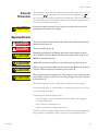
Section 1 Safety
Safety Warnings
Make sure you read and understand all instructions and safety precautions
listed in this manual before installing or operating your circulator. If you
have any questions concerning the operation or the information in this
manual, please contact us.
DANGER
DANGER indicates an imminently hazardous situation which, if not
avoided, will result in death or serious injury.
WARNING
WARNING indicates a potentially hazardous situation which, if not
avoided, could result in death or serious injury.
CAUTION
CAUTION indicates a potentially hazardous situation which, if not
avoided, may result in minor or moderate injury. It is also be used to alert
against unsafe practices.
The lightning flash with arrow symbol, within an equilateral triangle, is
intended to alert the user to the presence of non-insulated "dangerous
voltage" within the circulator's enclosure. The voltage magnitude is
significant enough to constitute a risk of electrical shock.
This label indicates the presence of hot surfaces.
This label indicates read the manual.
Observe all warning labels.
Never remove warning labels.
Refrigerated circulators should be left in an upright position for 24
hours before starting. This will ensure the lubrication oil has drained
back into the compressor.
The circulator's construction provides protection against the risk
of electrical shock by grounding appropriate metal parts. The
protection will not function unless the power cord is connected to a
properly grounded outlet. It is the user's responsibility to assure a
proper ground connection is provided.
The circuit protector located on the rear of the circulator is not
intended to act as a disconnecting means.
Operate the circulator using only the supplied line cord. The
circulator's power cord is used as the disconnecting device, it must
be easily accessible at all times.
Cole Parmer
1-1 Section 1 Safety
Never operate the bath without fluid in the reservoir.
Ensure the electrical cords do not come in contact with any of the plumbing connections or tubing.
Never place the circulator in a location or atmosphere where excessive heat, moisture, or corrosive
materials are present.
Ensure the tubing you select will meet your maximum temperature and pressure requirements.
Ensure all communication and electrical connections are made prior to starting the circulator.
Many refrigerants which may be undetectable by human senses are heavier than air and will replace the
oxygen in an enclosed area causing loss of consciousness. Refer to the circulator's nameplate and the
manufacturer's most current MSDS for additional information.
Other than water, before using any fluid, or when performing maintenance where contact with the fluid
is likely, refer to the manufacturer’s MSDS and EC Safety Data sheet for handling precautions.
Ensure, that no toxic gases can be generated by the fluid. Flammable gases can build up over the fluid
during usage.
When using ethylene glycol and water, check the fluid concentration and pH on a regular basis. Changes
in concentration and pH can impact system performance.
Ensure the fluid is at a safe temperature (20°C to 40°C) before handling or draining.
Never operate damaged or leaking equipment, or with any damaged cords.
Never operate the circulator or add fluid to the reservoir with panels removed.
Do not clean the circulator with solvents, only use a soft cloth and water.
Drain the bath before it is transported and/or stored in, near or below freezing temperatures.
Always turn the circulator off and disconnect the supply voltage from its power source before moving or
before performing any service or maintenance procedures.
Transport the circulator with care. Sudden jolts or drops can damage the its components.
Refer service and repairs to a qualified technician.
Performance of installation, operation, or maintenance procedures other than those described in this
manual may result in a hazardous situation and will void the manufacturer's warranty.
1-2
Cole Parmer
Description
Intended Use
Section 2 General
Information
The Cole Parmer Polystat® Heating Immersion Circulators are used
with cooling/heating and heating baths. All circulators can pump to an
external system. All have a digital display and easy-to-use touch pad, five
programmable setpoint temperatures, acoustic and optical alarms, and offer
adjustable high temperature protection.
The circulating bath is used as a temperature controlled bath or to circulate
to an application fluid to an externally to an application. It is designed for
continuous operation on a bench top and for indoor use in accordance with
all the procedures and requirements stated in this manual.
Sample Nameplate
Cole-Parmer
®
1-800-323-4340
®
BOM#: XXXXXXXXXXXX
Cole-Parmer
S/N: XXXXXXXXX
POLYSTATYYY
Y ZZZ
60HZ1PH
1PH X.X
X.XA
POLYSTAT
ZZZZ115V
115V 60HZ
A
R134A
XXX
OZ
HI
XXX
PSIG
LOW
XXX
PSIG
BOM#: XXXXXXXXXXXX
1-800-323-4340
1/1
S/N: XXXXXXXXX
POLYSTAT YYY ZZZZ 115V 60HZ 1PH X.X A
Use the
nameplate
the
rearXXX
to PSIG
identify
R134A
XXX
OZ HI XXX on
PSIG
LOW
your immersion
circulator/
1/1
circulating bath, its electrical requirements and, if applicable, the refrigeration
data. Y identifies the circulator and, if applicable, ZZZ the bath. For
example, 1 C6. The corresponding Cole Parmer catalog part numbers are
listed in the specification tables in this section.
Equipment Ratings
Ambient Temperature Range
10°C to 40°C (50°F to 104°F)
Maximum Relative Humidity
80% at 31°C (88°F)
Operating Altitude
Overvoltage Category
II
Pollution Degree
2
Degree of Protection
Cole Parmer
Sea Level to 2000 meters (6560 feet)
IP 20
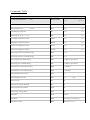
2-1 Section 2 General Information
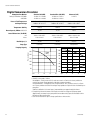
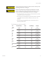
Digital Immersion Circulator
Nameplate Part Number
Catalog Part Number 115V/60Hz
230V/50Hz
Standard (1CL/1BR)
12120-01 or 12120-08
12120-02 or 12120-09
Standard Plus (2CL/2BR)
12120-03 or 12120-11
12120-04 or 12120-12
Advanced (3CL)
12120-13
-
Process Fluid Temperature
and Setpoint Range
Ambient +10° to 100°C
Ambient +18° to 212°F
Ambient +10° to 150°C
Ambient +18° to 302°F
Ambient +10° to 200°C
Ambient +18° to 392°F
Temperature Stability
±0.05°C
±0.05°C
±0.025°C
Heater Capacity KWatts 230V/115V1.2/1.0
Overall Dimensions (H x W x D)
mm
Inches
320.0 x 111.8 x 205.7
12.6 x 4.4 x 8.1
Net Weight kg/lb
Pump Type
Pumping Capacity
1.2/1.0
320.0 x 111.8 x 205.7
12.6 x 4.4 x 8.1
4.1/9.0
5.0/11.0
Force only
Force/Suction
500
350
300
Pressure (mbar)
340.4 x 144.8 x 218.4
13.4 x 5.7 x 8.6
4.1/9.0
Force only
2.0/1.2
400
Force
only
250
Force
300
200
200
100
150
0
-100
100
Suction
-200
50
-300
lpm
5
10 15 20
-400
lpm
5
10 15 20
• Lower process fluid temperature ranges available with supplemental cooling.
• Stability is measured as follows:
Heated baths – Fluid is water at 70°C, work area cover is on. Baths run in factory ambient at
nominal line voltage. Pump speed set to high with no external pumping.
Refrigerated baths – Fluid (specific heat of 0.55 Btu/lb-F) at -10°C, work area cover is on. Baths
run in factory ambient at nominal line voltage. Pump speed set to high with short insulated loop on
pump lines.
Stability is defined as ½ the total span of measured data over approximately 30 minutes.
• Pump testing is done with water at 20°C bath at nominal line voltage on high pump speed.
Approximately one meter loop on pump with flow transducer and (2) pressure transducers with a
ball valve to adjust the flow rate.
• Cole Parmer reserves the right to change specifications without notice.
2-2 Cole Parmer
Section 2 General Information
Stainless Steel Cooling/Heating Circulating Baths
Nameplate Part Number*
Catalog Part Number 115V/60Hz
230V/50Hz
Temperature Range
Bath Volume liters
gallons
Cooling Capacity watts @20°C
Refrigerant
Dimensions (H x W x L)**
mm
inches
Net Weight kg
lb
Nameplate Part Number*
Catalog Part Number 115V/60Hz
230V/50Hz
Temperature Range
Bath Volume liters
gallons
Cooling Capacity watts @20°C
Refrigerant
Dimensions (H x W x L)**
mm
inches
Net Weight kg
lb
Nameplate Part Number*
Catalog Part Number 115V/60Hz
230V/50Hz
Temperature Range
Bath Volume liters
gallons
Cooling Capacity watts @20°C
Refrigerant
Dimensions (H x W x L)**
mm
inches
Net Weight kg
lb
1 C6
12122-02
12122-04
1 C6F
12122-16
12122-18
1 C15
12122-32
12122-34
1 C15++
12122-46
12122-48
-20 to 100°C
-4 to 212°F
-20 to 100°C
-4 to 212°F
-28 to 100°C
-18 to 212°F
-35 to 100°C
-31 to 212°F
5.4 - 6.5
1.4 - 1.7
5.4 - 6.5
1.4 - 1.7
6.8 - 8.6
1.8 - 2.3
6.8 - 8.6
1.8 - 2.3
250
250
500
800
R134a
R134a
R134a
R404a
622.3 x 203.2 x 416.6
24.5 x 8.0 x 16.4
426.7 x 467.4 x 416.6
16.8 x 18.4 x 16.4
650.2 x 259.1 x 490.2
25.6 x 10.2 x 19.3
688.3 x 370.8 x 528.3
27.1 x 14.6 x 20.8
26.3
58.0
29.0
64.0
35.8
79.0
54.9
121.0
2 C15
12122-36
12122-38
2 C15++
12122-52
12122-54
-28 to 150°C
-18 to 302°F
-35 to 150°C
-31 to 302°F
6.8 - 8.6
1.8 - 2.3
6.8 - 8.6
1.8 - 2.3
500
800
R134a
R404a
650.2 x 259.1 x 490.2
25.6 x 10.2 x 19.3
688.3 x 370.8 x 528.3
27.1 x 14.6 x 20.8
35.4
78.0
54.9
121.0
3 C6
12122-12
12122-14
3 C6F
12122-26
12122-28
3 C15
12122-42
12122-44
3 C15++
12122-56
12122-58
-20 to 100°C
-4 to 212°F
-20 to 100°C
-4 to 212°F
-28 to 200°C
-18 to 392°F
-35 to 200°C
-31 to 392°F
5.4 - 6.5
1.4 - 1.7
5.4 - 6.5
1.4 - 1.7
6.8 - 8.6
1.8 - 2.3
6.8 - 8.6
1.8 - 2.3
250
250
500
800
R134a
R134a
R134a
R404a
640.0 x 203.2 x 416.6
25.2 x 8.0 x 16.4
444.5 x 467.4 x 416.6
17.5 x 18.4 x 16.4
655.3 x 259.1 x 490.2
25.8 x 10.2 x 19.3
706.1 x 370.8 x 528.3
27.8 x 14.6 x 20.8
27.2
60.0
29.9
66.0
36.3
80.0
55.8
123.0
L
*Refer to nameplate on the back of the bath for part number. Refer to pump curves on page 2-2.
**Overall Dimensions. Add ~15 mm to L for drain fitting.
2-3 Cole Parmer
Section 2 General Information
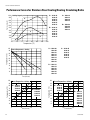
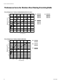
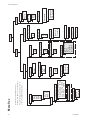
Performance Curves for Stainless Steel Cooling/Heating Circulating Baths
1000
A
800
Heat Load (watts)
A = 12122-46
12122-48
12122-52
12122-54
12122-56
12122-58
Cooling Capacity
900
700
600
B
500
400
= 12122-32
B
12122-34
12122-36
12122-38
12122-42
12122-44
C
300
200
D
100
C = 12122-16
12122-18
12122-26
12122-28
D = 12122-02
12122-04
12122-12
12122-14
-40 -20 0 +20+40+60+80+100
100
90
Temperature (°C)
A = 12122-02
12122-04
12122-16
12122-18
12122-12
12122-14
12122-26
12122-28
Time to Temperature - Cooling
Temperature (°C)
80
70
60
A
50
40
C
30
B
20
10
20
40
60
80
Time (minutes)
Temperature (°C)
100 Time to Temperature - Heating
90
80 A = 12122-12
12122-14
A
70 12122-26
B
60 12122-28
50
40
30
100
120
= 12122-32
B
12122-34
12122-36
12122-38
12122-42
12122-44
100
80
B = 12122-02
12122-04
12122-16
12122-18
70
60
50
40
30
20
20
10
10
0 204060
Time (minutes)
2-4 Time to Temperature - Heating
90
Temperature (°C)
0
C = 12122-46
12122-48
12122-52
12122-54
12122-56
12122-58
A = 12122-42
12122-44
12122-56
12122-58
A
B
B = 12122-32
12122-34
12122-36
12122-38
12122-46
12122-48
12122-52
12122-54
0 204060
Time (minutes)
Cole Parmer
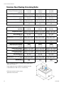
Section 2 General Information
Stainless Steel Heating Circulating Baths
Nameplate Part Number*
Catalog Part Number115V/60Hz
230V/50Hz
1 W7
12134-60
12134-62
1 W11
12134-64
12134-66
1 W24
12134-68
12134-70
Ambient +10 to 100°C
Ambient +18 to 212°F
Ambient +10 to 100°C
Ambient +18 to 212°F
Ambient +10 to 100°C
Ambient +18 to 212°F
5.1 - 6.5
1.3 - 1.7
7.5 - 9.5
2.0 - 2.5
15.4 - 19.6
4.1 - 5.2
396.2 x 215.9 x 363.2
15.6 x 8.5 x 14.3
396.2 x 302.2 x 363.2
15.6 x 11.9 x 14.3
396.2 x 363.2 x 561.3
15.6 x 14.3 x 22.1
10.0
22.0
11.3
25.0
15.9
35.0
2 W7
12121-02
12121-04
2 W11
12121-22
12121-24
2 W24
12121-42
12121-44
Ambient +10 to 150°C
Ambient +18 to 302°F
Ambient +10 to 150°C
Ambient +18 to 302°F
Ambient +10 to 150°C
Ambient +18 to 302°F
5.1 - 6.5
1.3 - 1.7
7.5 - 9.5
2.0 - 2.5
15.4 - 19.6
4.1 - 5.2
396.2 x 215.9 x 363.2
15.6 x 8.5 x 14.3
396.2 x 302.2 x 363.2
15.6 x 11.9 x 14.3
396.2 x 363.2 x 561.3
15.6 x 14.3 x 22.1
10.0
22.0
11.3
25.0
15.9
35.0
3 W7
12121-06
12121-08
3 W11
12121-26
12121-28
3 W24
12121-46
12121-48
Temperature Range**
(Low pump speed)
Ambient +10 to 200°C
Ambient +18 to 392°F
Ambient +10 to 200°C
Ambient +18 to 392°F
Ambient +10 to 200°C
Ambient +18 to 392°F
Temperature Range**
(High pump speed)
Ambient +25 to 200°C
Ambient +45 to 392°F
Ambient +20 to 200°C
Ambient +36 to 392°F
Ambient +10 to 200°C
Ambient +18 to 392°F
5.1 - 6.5
1.3 - 1.7
7.5 - 9.5
2.0 - 2.5
15.4 - 19.6
4.1 - 5.2
414.0 x 215.9 x 363.2
16.3 x 8.5 x 14.3
414.0 x 302.2 x 363.2
16.3 x 11.9 x 14.3
414.0 x 363.2 x 561.3
16.3 x 14.3 x 22.1
10.9
24.0
12.2
27.0
16.8
37.0
Temperature Range**
Bath Volume liters
gallons
Dimensions*** (H x W x L) mm
inches
Net Weight kg
lb
Nameplate Part Number*
115V/60Hz
230V/50Hz
Temperature Range*
Bath Volume liters
gallons
Dimensions*** (H x W x L) mm
inches
Net Weight kg
lb
Nameplate Part Number*
Catalog Part Number115V/60Hz
230V/50Hz
Bath Volume liters
gallons
Dimensions*** (H x W x L) mm
inches
Net Weight kg
lb
*Refer to nameplate on the back of the bath for part number. Refer to
pump curves on page 2-2.
**Lower temperature ranges available with supplemental cooling.
***Overall dimensions. Add ~15 mm to L for drain fitting.
• Cole Parmer reserves the right to change
specifications without notice.
L
2-5 Cole Parmer
Section 2 General Information
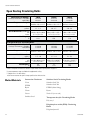
Performance Curves for Stainless Steel Heating Circulating Baths
Time to Temperature - Heating - Standard/Standard Plus Circulators
100
Temperature (°C)
90
A = 12134-60
12134-62
12121-02
12121-04
A
80
B
70
C
B = 12134-64
12134-66
12121-22
12121-24
60
50
40
C = 12134-68
12134-70
12121-42
12121-44
30
20
10
0 20406080100
120140
Time (minutes)
Time to Temperature - Heating - Advanced Circulator
100
90
Temperature (°C)
80
70
60
50
A
B
C
A = 12121-06
12121-08
B = 12121-26
12121-28
C = 12121-46
12121-48
40
30
20
10
0 20406080100
120
Time (minutes)
2-6 Cole Parmer
Section 2 General Information
Open Heating Circulating Baths
Polyphenylene oxide (PPO) Circulating Baths
Nameplate Part Number*
Catalog Part Number 115V/60Hz
230V/50Hz
Temperature Range**
1 W5P
12134-30
12134-32
1 W14P
12134-34
13134-36
1 W21P
12134-38
12134-40
Ambient +10 to 100°C
Ambient +18 to 212°F
Ambient +10 to 100°C
Ambient +18 to 212°F
Ambient +10 to 100°C
Ambient +18 to 212°F
4.3 - 5.3
1.1 - 1.4
11.3 - 14.1
3.0 - 3.7
18.0 - 22.5
4.8 - 5.9
348.0 x 190.5 x 388.6
13.7 x 7.5 x 15.3
348.0 x 358.1 x 452.1
13.7 x 14.1 x 17.8
348.0 x 358.1 x 642.6
13.7 x 14.1 x 25.3
5.4
12.0
6.8
15.0
7.7
17.0
1 W6A
12134-00
12134-02
1 W12A
12134-04
12134-06
1 W19A
12134-08
12134-10
Ambient +10 to 80°C
Ambient +18 to 176°F
Ambient +10 to 80°C
Ambient +18 to 176°F
Ambient +10 to 80°C
Ambient +18 to 176°F
5.5 - 7.0
1.5 - 1.8
10.1 - 12.8
2.7 - 3.4
15.6 - 19.9
4.1- 5.3
337.8 x 188.0 x 424.2
13.3 x 7.4 x 16.7
337.8 x 353.1 x 365.8***
13.3 x 13.9 x 14.4
337.8 x 353.1 x 543.6***
13.3 x 13.9 x 21.4
5.9
13.0
7.7
17.0
9.1
20.0
Bath Volume liters
gallons
Overall Dimensions (H x W x L)
mm
inches
Net Weight kg
lb
Transparent Acrylic Circulating Baths
Nameplate Part Number*
Catalog Part Number 115V/60Hz
230V/50Hz
Temperature Range**
Bath Volume liters
gallons
Overall Dimensions (H x W x L)
mm
inches
Net Weight kg
lb
*Refer to nameplate on the back of the bath for part number. Refer to pump curves on page 2-2.
**Lower temperature ranges available with supplemental cooling.
***Add ~6 mm to L for drain fitting.
• Cole Parmer reserves the right to change specifications without notice.
Wetted Materials
Immersion Circulators
Stainless Steel Circulating Baths
Viton
Stainless Steel 316
EPDM
Stainless Steel 304
Ryton
EPDM (drain fitting)
Ultem
Ryton
Vectra
Zotek-N (cover seal)
Stainless Steel
Transparent Acrylic Circulating Baths
Poly-acryl
Polyphenylene oxide (PPO) Circulating
Baths
Polyphenylenoxid
2-7 Cole Parmer
Section 2 General Information
2-8 Cole Parmer
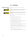
Section 3
Immersion Circulator
Only
Installation
The immersion circulator is designed for continuous operation and for
indoor use.
CAUTION
Never place the immersion circulator in a location where excessive
heat, moisture, inadequate ventilation, or corrosive materials are
present.
CAUTION
Carefully install the immersion circulator to ensure it does not fall
into the bath or that its line cord does not make contact with the bath
contents.
Immersion Circulators come with either an adjustable clamp or are mounted
on an adjustable bridge.
For immersion circulators equipped with a clamp:
• Attach and secure the clamp to your bath container.
• The maximum wall thickness is 25 mm (~1").
• The immersion depth is 75 to 145 mm (~3 to 5 3/4").
• Your bath container must be sturdy enough to support the weight of the
assembly, approximately 3.8 kilograms (8.5 pounds).
For immersion circulators equipped with a bridge:
• The bridge is designed to fit baths that are 400mm to 800 mm wide.
• Slide the bridge support rods to the desired length and secure them in
place with the supplied eight 3 mm Phillips Head screws.
• If possible, secure the bridge to your bath using the two supplied thumbscrews.
• The immersion depth is 75 to 145 mm (~3 to 5 3/4").
• Your bath container must be sturdy enough to support the weight of the
assembly, approximately 3.8 kilograms (8.5 pounds).
Cole Parmer
3-1 Section 3 Installation
Circulating Baths
CAUTION
CAUTION
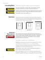
Ventilation
The circulator is designed for continuous operation and for indoor use.
Never place the bath in a location where excessive heat, moisture,
inadequate ventilation, or corrosive materials are present.
Refrigerated baths should be left in an upright position for 24 hours at
room temperature before starting. This will ensure the lubrication oil
has drained back into the compressor.
The bath can operate with 0 clearance on two exhaust sides as long as the
third exhaust side has unrestricted air flow. Blocked ventilation will increase
the bath's temperature, reduce its cooling capacity and, on refrigerated bath,
eventually lead to premature compressor failure.
Ventilation Options
Electrical
Requirements
DANGER
The circulator construction provides protection against the risk of
electrical shock by grounding appropriate metal parts. The protection
will not function unless the power cord is connected to a properly
grounded outlet. It is the user's responsibility to assure a proper
ground connection is provided.
The circulator is intended for use on a dedicated outlet.
Note If the circuit protector activates allow the temperature to cool before
resetting. Restart the circulator. Contact us if it activates again.
The circuit protection is designed to protect the circulator, and is not
intended as a substitute for branch circuit protection. Position the bath so it
is not difficult to operate the disconnecting device.
CAUTION
3-2 The circulator's power cord is used as the disconnecting device, it
must be easily accessible at all times.
Refer to the nameplate on the rear of the circulator for specific electrical
requirements. Voltage deviations of ± 10% are permissible. The outlet must
be rated as suitable for the total power consumption of the bath, see below.
Cole Parmer
Section 3 Installation
CAUTION
Ensure the electrical cords do not come in contact with any of the
plumbing connections or tubing.
CAUTION
Ensure all communication and electrical connections are made
prior to starting the circulator and that the cords do not come in
contact with any of the plumbing connections or tubing.
• For refrigerated baths, ensure the line cord from the bath is securely
connected to the rear of the circulator.
• For all, ensure the communications cable from the bath is connected
to the RJ45 connectors (similar to Ethernet) on the rear of the
circulator.
• For all, connect the supplied line cord to the circulator and to a
properly grounded outlet.
The following power options are available:
Unit
Cole Parmer
Volts1/Hertz/Phase
Amps2
Total Wattage
Plug Type
C6/C6F
1
115/60/1
230/50/1
11.5
6.8
1328
1573
N5-15
Country Specific
C6/C6F
3
115/60/1
230/50/1
11.5
10.3
1328
2373
N5-15
Country Specific
C15
1/2
115/60/1
230/50/1
11.7
6.9
1345
1596
N5-15
Country Specific
C15
3
115/60/1
230/50/1
11.7
10.4
1345
2396
N5-15
Country Specific
C15++
1/2
115/60/1
230/50/1
14.4
7.8
1662
1798
N5-20
Country Specific
C15++
3
115/60/1
230/50/1
14.4
11.3
1662
2598
N5-20
Country Specific
All Heated Units
1/2
115/60/1
230/50/1
9.6
5.8
1104
1338
N5-15
Country Specific
All Heated Units
3
115/60/1
230/50/1
11.3
9.3
1304
2138
N5-150
Country Specific
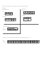
3-3 Section 3 Installation
Communications cable
from bath
I/O Circuit Protector
Cable connection required
for proper communication
between the bath and the
circulator.
Line cord connection
Line cord from bath
(cooling/heating baths only)
Outlet Flow
Return Flow
Remote Temperature
Sensor
USB Connection
1 2 3 4 5
6 7 8 9
Remote Temperature
Sensor
WARNING
Advanced Immersion Circulator
Never
apply line voltage to the connection.
The optional remote temperature sensor is enabled using the circulator,
see Section 4.
Pin
1
2, 3
4
5, 6 3-4 Return Flow
Outlet Flow
White
NA
White
NA
Pin
7
8
9
Red
NA
Red (4th wire not connected to the control board)
Cole Parmer
Section 3 Installation
External
Circulation
CAUTION
The plumbing connections for external circulation are located on the rear of
is the return flow from the external application.
is
the circulator.
the outlet flow to the external application (supply side). The connections are
16 mm O.D. Remove the union nuts and plates to install the supplied 8 mm
or 12 mm hose barbs and clamps.
Ensure the electrical cords do not come in contact with any of the
plumbing connections or tubing.
Approved Fluids
DANGER
The user is always responsible for the fluid used. Never use corrosive
fluids with this bath.
DANGER
Never use 100% glycol.
CAUTION
CAUTION
CAUTION
CAUTION
Handling and disposal of liquids other than water should be done
in accordance with the fluid manufacturers specification and/or the
MSDS for the fluid used.
Adjust the circulator's software to the fluid used, see Section 4.
When using water above 80°C closely monitor the fluid level, frequent
top-offs will be required. It will also create steam.
Water/glycol mixtures require top-offs with pure water, otherwise the
percentage of glycol will increase resulting in high viscosity and poor
performance.
The fluid information is only a guide since specifications may change.
Fisher Scientific takes no responsibility for damages caused by the selection
of an unsuitable bath fluid.
Unsuitable bath fluids are fluids which:
•are very highly viscous (much higher than 30 mPas at the respective working temperature)
•have corrosive characteristics or
•tend to break down at high temperatures
For fluid selection consider application requirements, operating temperature
range, material compatibility, safety concerns, and environmental issues.
Cole Parmer
3-5 Section 3 Installation
Chlorine — Short term usage of tap water may not cause any adverse
affects on the circulator or your application, but in the long term
problems may arise. To help alleviate these problems Fisher Scientific
recommends the use of chlorine.
The duration of time that chlorine remains in solution depends on factors
such as water temperature, pH and availability of direct sunlight. We
recommend maintaining chlorine levels at proper levels using chlorine test
strips, generally 1 to 5 ppm is adequate.
For best results, maintain the fluid pH between 6.5 and 7.5. Do not add
additional chlorine s without first determining the concentration ratio
that already exists in the fluid supply. Corrosion and degradation of the
circulation components can result from concentration ratios that are too
high. Contact our customer support for additional information.
5°C to 95°C — Distilled Water or Deionized Water (up to 3 MΩ-cm)
Normal tap water leads to calcareous deposits necessitating frequent
circulator decalcification, see table on next page.
Calcium tends to deposit itself on the heating element. The heating
capacity is reduced and service life shortened.
-30°C to 80°C — Water with Glycol
Below 5°C water has to be mixed with a glycol. The amount of glycol
added should cover a temperature range 5°C lower than the operating
temperature of the particular application. This will prevent the water/
glycol from gelling (freezing) near the evaporating coil.
Excess glycol deteriorates the temperature accuracy due to its high
viscosity.
other temperatures:
SIL 200 (5150 and 6200 only), SIL 300 (6200 only):
Silicone oil with a long life span (over 1 year) and negligible smell.
SYNTH 260 (6200 only):
Synthetic thermal liquid with a medium life span (several months) and
little smell annoyance.
Heat transfer fluids are supplied with an EC Safety Data Sheet.
DANGER
3-6 Ensure, when selecting the heat transfer fluid, that no toxic gases
can be generated. Flammable gases can build up over the fluid
during usage.
Cole Parmer
Section 3 Installation
CAUTION
Ensure the over temperature cut-off point is set lower than the fire
point for the heat transfer fluid selected.
CAUTION
The highest working temperature as defined by the EN 61010 (IEC 1010)
must be limited to 25°C below the fire point of the bath fluid.
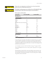
Water Quality and Standards
Process Fluid
Permissible (PPM)
Microbiologicals
(algae, bacteria, fungi)
Desirable (PPM)
0
Inorganic Chemicals
Calcium
<25
Chloride
<25
Copper
<1.3
0.020 ppm if fluid in contact with aluminum
Iron
<0.3
Lead
<0.015
Magnesium
<12
Manganese
<0.05
Nitrates\Nitrites
<10 as N
Potassium
<20
Silicate
<25
Sodium
<20
Sulfate
<25
Hardness
<17
Total Dissolved Solids
<50
Other Parameters
pH
Resistivity
6.5-8.5
0.01*
0
<0.6
<10
<1.0
<0.1
0
<0.1
<0.03
0
<0.3
<1.0
<0.3
<1
<0.05
<10
7-8
0.05-0.1*
* MΩ-cm (compensated to 25°C)
Unfavorably high total ionized solids (TIS) can accelerate the rate of galvanic
corrosion. These contaminants can function as electrolytes which increase
the potential for galvanic cell corrosion and lead to localized corrosion such
as pitting. Eventually, the pitting will become so extensive that refrigerant will
leak into the water reservoir.
As an example, raw water in the United States averages 171 ppm (of NaCl).
The recommended level for use in a water system is between 0.5 to 5.0 ppm
(of NaCl).
Recommendation: Initially fill the tank with distilled or deionized water. Do
not use untreated tap water as the total ionized solids level may be too high.
This will reduce the electrolytic potential of the water and prevent or reduce
the galvanic corrosion observed.
Cole Parmer
3-7 Section 3 Installation
Additional Fluid
Precautions
When working with fluids other than water:
• Do not use any fluid until you have read and understood the label and
the Material Safety Data Sheet (MSDS).
• Do not blend any fluids.
• Ensure any fluid residue or any other material is thoroughly removed
before filling the bath with a different fluid.
• Always wear protective clothing, especially a face shield and gloves.
• Avoid spattering on any of the circulator's components, always slowly
add fluid. When adding, point the opening of a container away from
yourself.
• Use fume hoods.
Filling Requirements
CAUTION
Ensure the reservoir drain port on the front of the bath is closed and that
all plumbing connections are secure. Also ensure any residue is thoroughly
removed before filling.
Before using any fluid refer to the manufacturer’s MSDS and EC
safety data sheets for handling precautions.
To avoid spilling, place your containers into the bath before filling.
With a low level WARNING the circulator continues to run, with a FAULT
the circulator will shut the refrigeration, pump and heater will shut down, see
Section 6. The low level warning is at approximately 4 cm (1 5/8”) below the
top, the low level fault is at approximately 5.5 cm (2 1/8”).
Avoid overfilling, oil-based fluids expand when heated.
When pumping to an external system, keep extra fluid on hand to maintain
the proper level in the circulating lines and the external system.
Draining
CAUTION
Note Monitor the fluid level whenever heating the fluid.
Before draining any fluid refer to the manufacturer’s MSDS and EC
safety data sheets for handling precautions.
Ensure the fluid is at a safe handling temperature, ~40°C. Wear
protective clothing and gloves.
• place a suitable vessel underneath the drain. If desired, attach an
8 mm id tube on the drain.
• slowly turn the drain plug until flow is observed.
3-8 Cole Parmer
Heating
Immersion
Circulator
Section 4 Operation
The Cole Parmer Heating Immersion Circulators have a digital display and
easy-to-use touch pad, five programmable setpoint temperatures, acoustic and
optical alarms and adjustable high temperature protection.
Use this button to place the circulator in and out of standby mode.
Use these navigation arrows to move through the displays and to adjust values.
Use this button to start/stop the circulator. This button is also used to make
and save changes on the display screen.
Use this button to cancel any changes and to return the circulator to its previous display. Canceling a change can only be made before the change is saved.
In some cases, it is also used to save changes.
NOTE Holding this button for five seconds resets the display contrast to the
default level and also brings up the language menu to change, if needed, the
displayed language. See Settings - Display Options in this Section.
Use the adjacent dial for adjusting the High Temperature Cutout. Details are
explained in this Section.
Cole Parmer
4-1 Section 4 Operation
Setup
CAUTION
Cooling/heating baths should be left in an upright position at
room temperature (~25°C) for 24 hours before starting. This
will ensure the lubrication oil has drained back into the compressor.
CAUTION
Before starting the circulator, double check all USB (optional),
Start Up
electrical and plumbing connections.
o not run the circulator until fluid is added to the bath. Have
D
extra fluid on hand. If the circulator will not start refer to Section 6
Troubleshooting.
I
• Place the circuit protector located on the front of
the circulator to the I position.
• Press
O
, the Start Display will appear.
Highlighted
Start Symbol
SP1
20.0°C
<>
• Ensure the start symbol has a highlight box around it, if not
use the arrow keys to navigate to the symbol.
Menu
Reservoir
Fluid
Temperature
24.2°C
Start Display
• Press
. The circulator will start and the start symbol
).
will turn into a stop symbol (
Stop Symbol
20.0°C
NOTE It will take 30 seconds for the compressor to start.
NOTE After start, check external plumbing connections for leaks.
The SP1 and Menu portions on the top of the display are used to
view and/or change the controller's settings. They are explained in
detail later in this Section.
4-2 Cole Parmer
Section 4 Operation
Status Display
If desired, press
Refrigeration Running
Symbol
to toggle between the Start/Status Displays.
Selected Reservoir Fluid
Pump Running Symbol
Heater Running Symbol
Reservoir Fluid
Temperature
Standby Mode
Cole Parmer
Water
24.2C
Status Display
Press
, the display will go blank and the circulator will be in the
standby mode.
4-3
Section 4 Operation
Changing the
Setpoint
NOTE You cannot adjust the setpoint closer than 0.1°C to either of
the fluid's system limits, see Fluids Type in this Section, or beyond the
circulator's temperature range.
The setpoint can be changed with the circulator running or not.
The Setpoint is the desired fluid temperature. The circulator can store
up to five setpoints, SP1 through SP5. The procedure for changing
the stored setpoint values is discussed later in this Section.
Use the navigation arrows and move to the SP1 window and then
to highlight it as shown below.
press
Setpoint Value Window
SP1
20.0°C
MENU
24.2°C
Use the up and down navigation arrows to bring up the desired setpoint
.
and then press
The display on the Setpoint Value Window will now indicate the corresponding setpoint's stored value.
SP2
35.0°C
MENU
24.2°C
If desired, you can change the displayed setpoint value by using the
navigation arrows to highlight the Setpoint Value Window and then
. The right-most digit will have a cursor beneath it.
pressing
Setpoint Value Window
35.0°C
Use the left and right arrows to move the cursor to the desired digit
and then use the up and down arrows to change the value. Once all the
to save the change.
desired changes are made, press
NOTE Using this procedure also changes the setpoint's stored value.
4-4 Cole Parmer
Section 4 Operation
Menu Displays
The circulator uses menus to view/change the settings.
NOTE The circulator does not need to be running to view/change these settings.
For all Menu displays, once
previous screen.
is pressed to change a display, you can press
1. Use the right arrow button to highlight
Menu and the display brings up the Main
Menu Display.
SP1
Menu
Settings
to return to the
2. Use the up and down arrow to highlight the
to bring up
desired setting and then press
additional submenus.
Application Settings
Display Options
System
Menu
See page 4-7.
SP1
Menu
Settings
Messages
Run Time
System
Configuration
Password/Reset
Menu
See page 4-12.
Menu
The Menu line, at the bottom of all the submenu displays, is another way to return the circulator back
to the Main Menu Display.
1. From any submenu display, use the down
arrow button to highlight Menu.
Application Settings
Display Options
2. Press
Display.
SP1
to return to the Main Menu
Menu
Settings
System
Menu
Pressing
from the Menu line returns you to
the previous screen.
Cole Parmer
4-5
4-6 Faults
Warnings
Audible Alarms
Optional
Low Level Warning
High Fault 83.00C
High Warning 83.00C
Low Warning 2.00C
Low Fault 2.00C
Temperature Alarms
Alarms
Setpoint
RTA int
RTA ext
SP1
SP2
SP3
SP4
SP5
Setpoints
Since the controller can only
display five lines of text at a time,
keep pressing the down arrow to
view any additional options.
Menu Tree
ON Time
OFF Time
Enabled
On/Off Timer
Time
Date
Set Clock
LOW
HIGH
Pump Adjustment
Glycol-Water
Water
Fluids Type
Application Settings
Optional
Serial Comm
Baud
Parity
Data Bits
Stop Bits
Interfaces
ON
OFF
Remote Sensor
ON
OFF
Energy Savings
ON
OFF
Auto Restart
Settings
Delay 60
Display Delay
Contrast 32
Display Contrast
English
Deutch
Francais
Language
C
F
K
Temp. Units
0.01
0.1
Temp. Resolution
Display Options
Menu
Reset
Calibration
PID Settings
Level
Password
Configuration
Unit
Pump
Run Time
Warnings
Faults
Messages
System
Section 4 Operation
Cole Parmer
Section 4 Operation
Settings - Application Settings is used to view/adjust the five Setpoints and Real
Temperature Adjustments (RTA) enable/disable the alarms, change the fluid type, set the pump speed,
configure the interfaces (optional), set the clock, turn the timer on or off, and turn auto restart and energy savings on or off.
1. With Application Settings highlighted
to view:
press
2. Scroll down for additional options:
Setpoints
Interfaces
Set Clock
Alarms
On/Off Timer
Fluid Type
Pump Adjustment
Auto Restart
3. With Setpoints highlighted, press
to display the list. Use the up/down arrows to
highlight the desired SP. NOTE Use the down
arrow to display SP5.
4. Press
Menu
Menu
.
SP1
SP1
xx.x
SP2
RTA int
xx.x
SP3
SP4
Menu
Menu
If this temperature on the Start/Status Display does not accurately reflect the actual temperature in the
reservoir, an RTA can be applied. The RTA can be set ±10°C (±18°F).
As an example, if the circulator's temperature is stabilized and displaying 20°C but a calibrated reference
thermometer reads 20.5°C, the RTA should be set to -0.5°C. After you enter a RTA value allow it to
stabilize before verifying the temperature in the bath. NOTE If display accuracy is required, we recommend repeating this procedure at various setpoint temperatures and on a regular basis.
NOTE You cannot adjust the setpoint closer than 0.1°C to either of the fluid's system limits, see Fluids
Type in this Section.
4. With the desired line highlighted press
.
The right-most digit will have a cursor beneath it.
Use the left and right arrows to move the cursor
to the desired digit and then use the up and down
arrows to change the value. Once all the desired
to save the change,
changes are made, press
to cancel it.
or
Cole Parmer
35.0°C
4-7
Section 4 Operation
Alarms is used to view/adjust the high and low temperature alarm limits, to enable/disable the audible
alarms and to configure the low level warning reaction.
1. With Alarms highlighted, press
display:
to
2. With Temperature Alarms highlighted,
to display:
press
Temperature Alarms
Audible Alarms
Low Level Warning
83.0°C
83.0°C
Low Warn
2.0°C
Low Fault
2.0°C
Menu
Menu
3. Highlight the desired limit and press
High Fault
High Warn
. Follow the same procedure used to change a setpoint.
If the Fault temperature is exceeded the circulator will shut down and, if enabled, the audible alarm
will sound. If the Warn temperature is exceeded the circulator will continue to run and, if enabled, the
audible alarm will sound. In both cases a message will be displayed.
High Fault cannot be set below High Warn.
High Warn cannot be set below Low Warn.
Low Fault cannot be set above High Warn.
Press
, or use the Menu window, to save
and return to the previous display.
1. With Audible Alarms highlighted, press
to display the alarms.
1. With Low Level highlighted, press
toggle the low level warning alarm on/off:
Highlight the desired alarm and press
toggle between enable and disable mode.
to
Faults
Warnings
Menu
to
Temperature Alarms
Audible Alarms
Low Level Warning
Menu
, or use the Menu window, to save
Press
and return to the previous display.
If Faults is enabled the alarm will sound when a
fault occurs. If Warnings is enabled the alarm
will sound when a warning occurs.
Press
, or use the Menu window, to save
and return to the previous display.
4-8 Cole Parmer
Section 4 Operation
Fluids Type is used to identify the type of fluid used. The controller uses the fluid type to automati-
cally set certain operating parameters.
1. With Fluid Type highlighted, press
display the list of acceptable fluids.
to
Highlight the desired fluid and press
select it.
>
Water
to
EG-Water
PG-Water
High °C
Low °C
Distilled Water
+98
+2
DI Water (up to 3 Ω)
+98
+2
EG-Water
+103
-35
PG-Water
+103
-23
All circulators:
For Standard Plus circulators:
<
Other
Fluid system limits
SIL 200
Menu
2. With the desired fluid selected press
, or
use the Menu window, to save and return to the
previous display.
Pump Adjustment is used to review/set the
desired pump speed.
+153
+17
For Advanced circulator:
SIL 200
+203
+17
SIL 300
+203
+77
SYNTH 260
+203
+42
NOTE The range is also limited by the bath temperature range, see Section 2.
1. With Pump Adjustment highlighted, press
to display the speeds.
to
Highlight the desired speed and press
select it.
>
Low
<
High
Menu
Cole Parmer
4-9
Section 4 Operation
On/Off Timer is used to enable and set the
Set Clock is used to set the controller's time
controller's timer.
>
(hr : min : sec) and date (year - month - day).
1. With On/Off Timer highlighted, press
to display the on ( I ) and off (O) time as well as
the enable box.
XX : XX : XX
XXXX - XX - XX
<
I: 2010-01-01
Menu
O: 2010-01-01
08:00:00
08:00:00
Enable
Menu
After setting the on and off times select Enable
to activate the timer.
Auto Restart is used to enable the auto restart feature. When enabled, the circulator will automatically restart after a power failure or power interruption condition.
1. With Auto Restart highlighted, press
to toggle between enable and disable.
Energy Saving is used to enable the energy savings mode. The Energy Saving mode is primarily
designed for applications running under a stable load. Enabling the mode saves energy by reducing the
circulator's heater power and cooling requirements. This can result in substantial energy savings over the
life of the circulator . The default setting is ON.
1. With Energy Saving highlighted, press
to toggle between enable and disable. The default is
disable except for C15++ baths which have an enable default.
Interfaces is used to enable/configure the optional serial communications feature.
1. With Interfaces highlighted, press
display the list of parameters.
Serial Type
RS232, RS485, Off
Baud
19200, 9600, 4800, 2400, 1200, 600, 300
Parity
None, Odd, Even
>
Data Bits
8
Stop Bits
1, 2
See the Appendix for additional information.
.
Highlight the desired parameter and press
to view the available options.
Serial Type
Baud
Parity
Data Bits
Menu
4-10 Available options:
<
to
Cole Parmer
Section 4 Operation
Settings - Display Options is used to view/adjust the display's Temperature Units, the
Temperature Resolution, the displayed Language, and the Display Contrast and Display Delay.
1. With Temp. Unit highlighted press
.
Use the up/down arrows to highlight the desired
temperature scale.
.
Press
2. With Temp. Resolution highlighted
.
press
Use the up/down arrows to highlight the desired
.
resolution. Press
°C
0.01
°F
0.1
°K
Menu
.
3. With Language highlighted press
Use the up/down arrows to highlight the desired
language. (Scroll down for additional languages.)
.
Press
Menu
4. With Display Contrast highlighted press
.
again and use the up/down arrows
Press
keys to change the contrast. With the desired conagain.
trast showing, press
Contrast 32
English
Deutsch
Francais
Espanol
Menu
Menu
for five seconds resets the display contrast to the default level and also brings up
NOTE Holding
the language menu to change, if needed, the displayed language.
5. With Display Delay highlighted press
to enable/disable it.
Use the up/down arrows to highlight the time
again.
and press
Use the up/down arrows to change the value.
.
Once the desired delay is displayed press
Cole Parmer
Delay
60 sec
With Display Delay enabled and the Start
Display showing, if no arrows are pressed the
Start Display will change to the Status Display
after the delay expires.
4-11
Section 4 Operation
System Messages is used to view any Warning or Fault messages.
1. With Messages highlighted, press
display the options.
to
Warnings
Faults
Menu
System Run Time is used to view the circulator (Unit) and pump operating hours.
1. With Run Time highlighted, press
display the times.
Unit
xxx hours
Pump
xxx hours
to
Menu
System Configuration is used to view the circulator's configuration.
1. With Configuration highlighted, press
to display the settings.
Head
1
FW
XXXXXXX.A
Checksum
XXXX
Bath
FW NOTE Heating baths display
Bath Unknown.
C6; 115V
XXXXXXX.A
Menu
4-12 Cole Parmer
Section 4 Operation
System - Password/Reset is used only by a qualified technician. Changing the password enables
circulator reset options, the temperature sensor calibration procedure and displays PID values.
1. With Password/Reset highlighted, press
to display:
2. Press
Level User
Level User
Password 1
Password 0
Menu
Menu
3. Press
and change the number to 1.
to display:
NOTE The circulator resets to the User mode
whenever it is turned off. The display also resets to
the User mode whenever the Start/Status Display is displayed continuously for 10 minutes.
Level Operator
Password 1
Reset
Calibration
Menu
Scroll down to display PID Tuning, see page
4-15.
1. If desired, highlight Reset and press
display:
to
Reset user settings
Reset PID settings
Reset both
Menu
Highlight the desired reset option and press
.
A confirmation message will appear, press
again.
Cole Parmer
4-13
Section 4 Operation
1. To calibrate the temperature sensor highlight
Calibration and press
to display:
2. With the desired sensor highlighted, press
to display:
NOTE Ensure the RTA is set to 0 before doing a
calibration.
Internal RTD
Calibrate
External RTD
Restore User Cal
Save User Cal
Restore Factory Cal
Menu
3. With Calibrate highlighted, press
display:
Internal RTD
xx.x
High
xx.x
Low
Calibrate SP
to
xx.x
High
xx.x
xx.x
Low
xx.x
xx.x
Calibrate SP
xx.x
Menu
xx.x
High
xx.x
Low
xx.x
Calibrate SP
xx.x
Menu
Internal RTD
Menu
5. Press
and enter the desired calibration
temperature .
Internal RTD
4. Highlight the SP temperature box and enter
either the desired high or low setpoint value.
6. Highlight Calibrate and the press
complete the procedure.
Internal RTD
xx.x
High
xx.x
Low
xx.x
Calibrate SP
xx.x
to
Menu
7. Repeat for the other calibration point.
Once the calibration is complete you can store it into the circulator's memory by selecting Save User
Cal and pressing
.
You can later restore the same calibration by highlighting Restore User Cal and pressing
.
Another option is to restore the factory calibration values by highlighting Restore Factory Cal and
.
pressing
The Save Factory Cal option is designed to be used only by a qualified technician.
4-14 Cole Parmer
Section 4 Operation
1. With PID Tuning highlighted, press
display:
Cool PID
Heat PID
Menu
3 . If required, press
to
2. Highlight the desired PID and press
display:
P
xx.x
I
x.xx
D
x.xx
to
Menu
to change the value.
P
xx.x
I
x.xx
D
x.xx
Factory values are:
P = 05.0
I = 0.10
D = 0.00
Menu
High Temperature
Cutout
HTC (Temperature range
varies with type of immersion circulator.)
To protect your application, the adjustable High Temperature Cutout
(HTC) ensures the heater will not exceed temperatures that can cause
serious damage. A temperature sensor is located in the bath fluid. A
High Temperature fault occurs when the temperature of the sensor
exceeds the set temperature limit.
In the event of a fault the circulator will shut down and display a fault
message, see Section 6. The cause of the fault must be identified and
corrected before the circulator can be restarted.
The cutout is not preset and must be adjusted. To set the cutout, with
the circulator off use a flat head screwdriver to turn the red dial fully
clockwise. Start the circulator. Adjust the setpoint for a few degrees
higher than the highest desired fluid temperature and allow the bath
to stabilize at the temperature setpoint. Then slowly turn the dial
counterclockwise until the circulator shuts down and the message
appears. Press the enter key to clear the message.
Before you can restart the circulator it has to cool down a few degrees.
To restart, press the black ring surrounding the red dial - and then
press the enter key again. If Auto Restart is enabled the circulator will
restart, if disabled use the Start Up procedure.
NOTE: We recommend periodically rechecking operation or if the
circulator is moved.
Cole Parmer
4-15
Section 4 Operation
Stopping the
Circulator
Ensure the stop symbol is highlighted, if not use the arrow keys to navigate to the symbol.
. The circulator will stop and the stop symbol will turn into a
Press
).
start symbol (
Stop Symbol
SP1
20.0°C
Menu
24.2°C
Power Down
. The display will go blank.
I
Shut Down
Place the circuit protector on the front of the circulator to the
O position.
CAUTION
Using any other means to shut the circulator down can reduce the
life of the compressor.
CAUTION
Always turn the circulator off and disconnect it from its supply
voltage before moving.
CAUTION
The circuit protector located on the front of the circulator is not
intended to act as a disconnecting means.
Restarting
4-16 Press
O
NOTE When quickly restarting, the compressor may take up to 10 minutes before it starts to operate.
Cole Parmer
Section 5
Preventive Maintenance
WARNING
Laboratory Grade Ethylene glycol (EG) is poisonous and flammable.
Before performing any preventive maintenance refer to the
manufacturer’s most current MSDS for handling precautions.
CAUTION
Disconnect the power cord prior to performing any maintenance.
Handle the circulator with care, sudden jolts or drops can damage its
components.
There are no user serviceable components within the equipment panels.
Cleaning
After time, the circulator's stainless steel surfaces may show spots and
become tarnished. Normal stainless steel cleaners can be used.
Clean the bath vessel and built-in components at least every time the bath
liquid is changed. Use water and a soft cloth.
CAUTION
Do not use scouring powder.
CAUTION
For cleaning the baths do not use any substances which contain
solvents.
Condenser Fins
The inside of the bath must be kept clean in order to ensure a long service
life. Substances containing acidic or alkaline substances and metal shavings
should be removed quickly as they could harm the surfaces causing corrosion.
If corrosion (e.g., small rust marks) should occur in spite of this, cleaning
with stainless steel caustic agents has proved to be suitable. These substances
should be applied according to the manufacturer's recommendations.
For refrigerated baths, in order to maintain the cooling capacity of the
bath, clean the fins two to four times per year, depending on the operating
environment.
Switch off the circulator and unplug the power cord.
Clean the fins with compressed air.
For extreme soiling a qualified technician will need to remove the cooling
compressor casing.
Hoses
Cole Parmer
Inspect and tighten the circulator's external hoses and clamps daily.
5-1 Section 5 Preventive Maintenance
Testing the Safety
Features
The safety features for high temperature protection and low liquid level
protection must be checked at regular intervals. We recommend checking
at least twice a year or if the circulator is moved.
High temperature protection
Set a cut-off temperature that is lower than the desired setpoint
temperature.
Switch on the circulator and ensure it shuts down at the set cut-off
temperature.
If the circulator does not shut down have the it checked by a qualified
technician.
Reset the safety to the desired temperature.
CAUTION
Acrylic unit’s maximum high temperature setting should be limited
to the temperature indicated on the label on the front of the bath,
80°C.
Low liquid level protection
With the circulator on, use a screwdriver and slowly push down on each
sensor until the error message indicated below appears.
See Section 6 for details on error messages.
If either message does not appear, have the circulator checked by a
qualified technician.
FAULT:
HTC/Low Level Fault
PRESS ENTER
LLC
Low Level Cutout
(Advanced only)
5-2 Cole Parmer
Section 6
Error Displays
Troubleshooting
Error messages are cleared by pressing the enter key (
). Once the cause
of the error message is identified and corrected, to restart the circulator on circulators with an HTC error press the black ring surrounding the red
dial - and then for all circulators press the enter key again. If Auto start is
enabled the circulator will restart, if disabled use the Start Up procedure.
FAULT:
HTC/Low Level Fault
PRESS ENTER
Error Message (Typical)
Fault Displays
The heating element, pump and, if applicable, refrigeration shut down with a
fault. A fault also sounds the alarm, if enabled.
Message
High Fixed Temp.
Action
• circulator's nonadjustable high temperature
protection limit exceeded
• check fluid selection
• check environmental conditions
High Temperature • adjustable high temperature protection limit
exceeded
• check limit setting
• check fluid selection
• ensure circulator has adequate ventilation
High Temperature • check voltage supply
Refrigeration
• the refrigeration may need servicing
• check for obstructions to air flow
HPC
High Press. Cutout • the refrigeration may need servicing
• if the fluid level is greater than approximately
HTC/Low Level
5.5 cm below the tank top it is a low level fault.
Fault
Fill fluid to proper level.
• if not, high temperature protection limit
exceeded
• check limit setting
• allow circulator to cool down to at least 10°C
cooler than the HTC setting
• reset HTC by pressing black ring
• set HTC to desired setting
Cole Parmer
6-1 Section 6 Troubleshooting
LLC
Low Level Cutout
Low Fixed Temp.
Low Temperature
Motor Fault
MOL
Motor Overload
Open RTD1
Internal
• reservoir fluid level too low for safe operation
• check fluid level
• check for leaks
• circulator's nonadjustable low temperature
protection limit exceeded
• check fluid selection
• adjustable high temperature protection limit
exceeded
• check limit setting
• check fluid selection
• it can take over 10 minutes for the motor
temperature to get low enough before the
circulator can be restarted
• allow circulator to cool down
• open internal temperature sensor
Open RTD2
External
• open external temperature sensor
Shorted RTD1
Internal
• shorted internal temperature sensor
Shorted RTD2
External
• shorted external temperature sensor
Warning Displays
The circulator will continue to run with a warning. A warning also sounds the
alarm, if enabled.
Bad Calibration
High Temperature
Low Level
Low Temperature
6-2
• redo calibration
• adjustable high temperature protection limit
exceeded
• check limit setting
• check fluid selection
• reservoir fluid level too low for safe operation
• check fluid level
• adjustable low temperature protection limit
exceeded
• check limit setting
• check fluid selection
Cole Parmer
Section 6 Troubleshooting
Checklist
Circulator will not start
Check for error codes, see Error Codes in this section.
Ensure the circuit protector is in the on ( I ) position.
Make sure supply voltage is connected and matches the unit's nameplate rating
±10%
No display
Recycle the circulator's circuit protector.
Circulator will not circulate process fluid
Check the reservoir level. Fill, if necessary.
Check the application for restrictions in the cooling lines.
The pump motor overloaded. The pump's internal overtemperature overcurrent
device will shut off the pump causing the flow to stop. This can be caused by
low fluid, debris in system, operating circulator in a high ambient temperature
condition or excessively confined space. Allow time for the motor to cool down.
Make sure supply voltage matches the circulator's nameplate rating ±10%.
Inadequate temperature control
Verify the setpoint.
On refrigerated baths, make sure the condenser is free of dust and debris.
Check the fluid concentration.
Ensure installation complies with the site requirements in Section 3.
Make sure supply voltage matches circulator nameplate rating ±10%.
If the temperature continues to rise, make sure your application's heat load does
not exceed the rated specifications.
Check for high thermal gradients (e.g., the application load is being turned on
and off or rapidly changing).
Circulator shuts down
Ensure
button wasn't accidently pressed.
Ensure the circuit protector is in the on ( I ) position.
Check for error codes.
Make sure supply voltage is connected and matches the circulator's nameplate
rating ±10%.
Restart the circulator.
Cole Parmer
6-3 Section 6 Troubleshooting
USB Driver Not Recognized
If your operating system does not automatically recognize the optional driver
log on to:
http://www.ftdichip.com/FTDrivers.htm
for instructions.
6-4
Cole Parmer
Appendix
AC Serial Communications Protocol
Serial communication is accomplished through the USB port on the chiller. If your operating system does
not automatically recognize the optional driver log on to: http://www.ftdichip.com/FTDrivers.htm for
instructions.
Note This appendix assumes you have a basic understanding of communications protocols. Information on
the NC, STANDARD and NAMUR protocols is available upon request.
Note Keypad operation is still available with serial communications enabled.
All commands must be entered in the exact format shown in the tables on the following pages. The tables
show all commands available, their format and responses. Chiller responses are either the requested data or
an error message. The chiller response must be received before the host sends the next command.
The host sends a command embedded in a single communications packet, then waits for the chiller’s
response. If the command is not understood, the chiller responds with an error command. Otherwise, the
chiller responds with the requested data.
Commands are not case sensitive. Upper or lower case letters may be used. Commands are listed in the
Commands Table, error responses are given in the Errors Table, and symbols are shown in the Key Table.
Key
Symbol
Meaming
[B]
A binary value 0 or 1 (0 = Off, FALSE or Disable(d); 1 = On, TRUE or Enable(d)).
[CR]
Carriage return – used as the termination character.
[U]
Text representing the units associated with a value.
[V]
A value that can be requested in a read command or sent as part of a set command.
[VMAX]
Maximum allowed value. Part of error message when set value is too high.
[VMIN]
Minimum allowed value. Part of error message when set value is too low.
Value: Read commands return analog [V] or bit [B] values or settings, while set commands send analog or bit
settings. Read commands return values with the same displayed precision. Set command messages missing the
space character between the command and the setting will be rejected, as the user’s intent is unclear.
Units: A read command returning an analog [V] value or setting, will include the units [U] associated with that
value or setting. A set command sending an analog value will not include the units. The units returned by the
complementary read command are assumed.
Termination character: A carriage return [CR] is used to terminate command and response messages. (Typically
the “Enter” key on the keyboard.)
Note The inter-character timeout (time between transmitted characters) is set to 30 seconds. Exceeding the
timeout will clear the receiver buffer and require the message to re retransmitted.
Note Special characters (backspace, delete, insert, etc.) are not recognized by the protocol and generate error
responses.
1
Commands Table:
Commands
2
All messages from master and slave are terminated with a carriage return [CR]
Command Description
Notes
Master Sends
Sample Slave Response
Read Temperature
Internal
RT
[V]C
FK
Read Temperature 2
External
RT2
[V]C
FK
Read Displayed Setpoint
RS
[V]C
FK
Read Setpoint X (X = 1 to 5)
RSX
[V]C
FK
Read High Temperature Fault
RHTF
[V]C
FK
Read High Temperature Warn
RHTW
[V]C
FK
Read Low Temperature Fault
RLTF
[V]C
FK
Read Low Temperature Warn
RLTW
[V]C
FK
Read Proportional Heat Band Setting
RPH
[V]%
Read Proportional Cool Band Setting
RPC
[V]%
Read Integral Heat Band Setting
RIH
[V]Repeats per minute
Read Integral Cool Band Setting
RIC
[V]Repeats per minute
Read Derivative Heat Band Setting
RDH
[V]Minutes
Read Derivative Cool Band Setting
RDC
[V]Minutes
Read Temperature Precision
RTP
[V]
Read Temperature Units
RTU
[V}
Read Unit On
RO
[B]
Read External Probe Enabled
RE
[B]
Read Auto Restart Enabled
RAR
[B]
Read Energy Saving Mode
REN
[B]
Read Time
RCK
hh:mm:ss
Read Date
RDT
mm/dd/yyyy or dd/mm/yyyy
Read Date Format
RDF
MM/DD/YYYY or
/
/
(echo off)
Alternate units
C,F,K
Commands
All messages from master and slave are terminated with a carriage return [CR]
Master Sends
Sample Slave Response
Read Firmware Version
RVER
[V]
Read Firmware Checksum
RSUM
[V]
Set Displayed Setpoint
SS [V]
OK
Set Setpoint X (X = 1 to 5)
SSX [V]
OK
Set High Temperature Fault
SHTF [V]
OK
Set High Temperature Warning
SHTW [V]
OK
Set Low Temperature Fault
SLTF [V]
OK
Set Low Temperature Warning
SLTW [V]
OK
Set Proportional Heat Band Setting
SPH [V]
OK
Set Proportional Cool Band Setting
SPC [V]
OK
Set Integral Heat Band Setting
SIH [V]
OK
Set Integral Cool Band Setting
SIC [V]
OK
Set Derivative Heat Band Setting
SDH [V]
OK
Set Derivative Cool Band Setting
SDC [V]
OK
Set Temperature Resolution
STR [V]
OK
Set Temperature Units
STU [V] C,F,K
OK
Set Unit On Status
SO [B]
OK
Set External Probe On Status
SE [B]
OK
Set Auto Restart Enabled
SAR [B]
OK
Set Energy Saving Mode
SEN [V]
OK
Set Pump Speed
SPS [V] L, H
Command Description
Notes
(echo off)
Alternate units
OK
3
Errors Table:
Errors
Error Description
4
Notes Slave Responds
Not defined, not implemented or incorrectly formatted
? Unsupported command
Extra characters…
? Format error
Set value too high
? Maximum allowed is [VMAX]
Set value too low
? Minimum allowed is [VMIN]
Argument to binary set command not 0 or 1
? Value must be 0 or 1
Set command attempted while in read only mode
? Mode is read only
Set command failed (e.g. SO 1 with low level)
? Failed
RUFS Read Unit Fault Status
This command returns 5 values. These are decimal representations of hexadecimal values. Each individual bit of the value
represents a different warning, fault or status.
decimal
hex
B7 B6 B5 B4 B3 B2 B1 B0
1
1
0
0 0 0 0 0 0 1
2
2
0
0 0 0 0 0 1 0
4
4
0
0 0 0 0 1 0 0
8
8
0
0 0 0 1 0 0 0
16
10
0
0 0 1 0 0 0 0
32
20
0
0 1 0 0 0 0 0
64
40
0
1 0 0 0 0 0 0
128
80
1
0 0 0 0 0 0 0
Value
V1
V2
V3
V4
V5
Description of bits
B0 – b5 unused
B6 rtd1 shorted
B7 rtd1 open
B0 HTC fault
B1 high RA temperature fault
B2 – b7 unused
B0 low level warn
B1 lo temperature warn
B2 high temperature warn
B3 low level fault
B4 lo temperature fault
B5 high temperature fault
B6 low temperature fixed fault
B7 high temperature fixed fault
B0 PWM heat duty cycle > 0
B1 compressor On/Off
B2 Pump On status
B3 Unit On status
B4 Unit Stopping
B5 Unit fault status
B6 unused
B7 Beeper On status
B0 Pump speed fault
B1 MOL fault
B2 HPC fault
B3 Cool Icon On steady (unit is cooling at max capacity)
B4 Cool Icon flashing
(unit is
B5 Heat Icon On steady
B6 Heat Icon flashing
B7 External sensor controlling
5
Refer to Key table on page 1 for explanation of symbols and their meanings.
Examples:
Set Setpoint:
Read Temperature:
Host
Host
R T
Command
S
S
Command
CR
[CR]
Controller:
O
K
Command
Accepted
Controller:
2
0
.
[V]
0
Read Temperature 2:
R T 2
Host:
Controller: 2 0 .
C CR
[U] [CR]
2 0
[V]
CR
[CR]
CR
[CR]
CR
0 C [CR]
Set Setpoint to -22°C when minimum allowed is -20°C: Minimum allowed is [VMIN]
Host:
Controller:
6
S
?
S
M
- 2 2 CR
i n i m u m
a
l
l
o
w
e d
i s
- 2 0 CR
DECLARATION OF CONFORMITY
Manufacturer:
Cole Parmer
Address:
625 East Bunker Court
Vernon Hills, IL 60061
Year of inception 2011
We declare that the following products conform to the Directives and Standards listed below.
Products: Polystat cooling/heating and heating liquid baths, non refrigerated heating liquid baths and
immersion liquid circulators with the following bill of material numbers.
212111100, 212111800, 212112100, 212112800, 212113100, 212113800, 212114100, 212114800,
212115100, 212115800, 212116100, 212116800, 212117100, 212117800, 212118100, 212118800,
212119100, 212119800, 212131100, 212131800, 212132100, 212132800, 212133100, 212133800,
212134100, 212134800, 212180100, 212180800, 212190100, 212190800, 212211100, 212211800,
212212100, 212212800, 212213100, 212213800, 212233100, 212233800, 212234100, 212234800,
212280100, 212280800, 212290100, 212290800, 212311100, 212311800, 212312100, 212312800,
212313100, 212313800, 212331100, 212331800, 212332100, 212332800, 212333100, 212333800,
212334100, 212334800, 212390100, 212390800.
All models rated 115 Volts, 60 Hz or 230 Volts, 50 Hz
Equipment Class:
Measurement, control and laboratory.
Directives and Standards:
2004/108/EC – Electromagnetic Compatibility ( EMC Directive ):
EN 61326-1: 2006 – Electrical equipment for measurement, control, and laboratory
use – EMC Requirements - EMC Class A.
2006/95/EC – Low Voltage Directive ( LVD ):
EN 61010-1: 2001 – Safety requirements for electrical equipment for measurement,
control, and laboratory use – General Requirements.
EN 61010-2-010: 2003 – Safety requirements for electrical equipment for measurement,
control, and laboratory use – Part 2-010: Particular requirements for laboratory equipment for
the heating of materials.
Date:
18 October 2011
D of C
DWG #
096221 .1
096221
Form 094233
REV 17 Apr 07
RoHS DECLARATION OF CONFORMITY
Manufacturer:
Cole Parmer
Address:
625 East Bunker Court
Vernon Hills, IL 60061
Products: Polystat cooling/heating and heating liquid baths, non refrigerated heating liquid baths and
immersion liquid circulators with the following bill of material numbers.
212111100, 212111800, 212112100, 212112800, 212113100, 212113800, 212114100, 212114800,
212115100, 212115800, 212116100, 212116800, 212117100, 212117800, 212118100, 212118800,
212119100, 212119800, 212131100, 212131800, 212132100, 212132800, 212133100, 212133800,
212134100, 212134800, 212180100, 212180800, 212190100, 212190800, 212211100, 212211800,
212212100, 212212800, 212213100, 212213800, 212233100, 212233800, 212234100, 212234800,
212280100, 212280800, 212290100, 212290800, 212311100, 212311800, 212312100, 212312800,
212313100, 212313800, 212331100, 212331800, 212332100, 212332800, 212333100, 212333800,
212334100, 212334800, 212390100, 212390800.
All models rated 115 Volts, 60 Hz or 230 Volts, 50 Hz
Cole Parmer certifies that the above Polystat models meet the requirements of DIRECTIVE
2002/95/EC, Restriction of Hazardous Substances Directive ( RoHS ). Cole Parmer certifies
that these Polystat models contain less than the following indicated amounts of the six RoHS
banned substances with the exemption stated in Note 2 below:
Substance
Threshold Level
Lead…
Pb
Less than 0.1% 1 & 2
Mercury…
Hg
Less than 0.1% 1
Hexavalent Chromium …
Cr (VI)
Less than 0.1% 1
Polybrominated Biphenyls …
PBB
Less than 0.1% 1
Polybrominated Diphenyl Ethers … PBDE
Less than 0.1% 1
Cadmium …
Less than 0.01% 1
Cd
Notes:
1. Tolerated maximum concentration value by weight in homogeneous materials.
2. Exemptions - Lead as an alloying element in steel containing up to 0.35% lead by
weight, aluminum containing up to 0.4% lead by weight and as a copper alloy
containing up to 4% lead by weight.
Date:
18 October 2011
D of C
DWG #
096221 .4
096221
Form 094233
REV 17 Apr 07