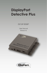
1
Optional
Accessories
DVI Detective Plus
Save the EDID -- now for HDTV equipment as well as Computers.
Computers and HDTV video source devices can sometimes lose the EDID -- basically the
electronic identification of a display which lists its possible resolutions and frequencies. When
displays are switched away or disconnected and then reconnected, the EDID can be lost and the
computer or HD video source device can lose the ability to display the image properly.
DVI Cables
The Gefen DVI Detective Plus allows you to switch or relocate HDTV or Computer video displays
while "tricking" the source devices into thinking that the display is still present -- maintaining smooth
video operations throughout the process.
Related Products
How It Works
You simply program the DVI Detective Plus for the display that you will use, by performing a
programming step while having the device connected to the display and a power adapter. Next, you
put it into place on the video output of your video source and restart your equipment. When all
sources and displays are powered on, seamless functioning of video source and display equipment
will commence.
DVI Detective
(discontinued)
External buttons make EDID programming and settings operations a breeze -- formerly, some
operations could require opening the unit.
Note:
DVI Detective N
The DVI Detective Plus includes 4 built-in manually-selectable generic EDIDs (display identities) for
forcing several standard home theater setups with multi-channel audio and standard HDTV
resolutions. This functionality is vital when equipment reaches a state of indeterminite function and
will not respond to signals or controls properly, and a certain resolution size with specific audio
must be forced upon all connected equipment.
DVI, HDCP & HDMI Defined
Features:
Store EDID information for displays
Supports resolutions up to 1920x1200, 2K, and 3840x2400 (Dual Link)
Keeps computer systems from deactivating inactive DVI ports
Can eliminate CAT-5 lines used to carry DDC signals when extending computer video
Passes HDCP copy-protection protocols for full HDTV, using an HDMI to DVI adapter (not
included)
z No power required after initial programming
z
z
z
z
z
Specifications:
z
z
z
z
z
DVI Connector: DVI-I 29 pin female
Power Supply: 5V DC
Power Consumption: 5 watts (max)
Dimensions: 2.7"W x 1.5"H x 2"D
Shipping Weight: 1 lbs
Package Includes:
z one DVI-DL 1-foot cable MM
z one 5VDC Power Supply
z one User Manual
EXT-DVI-EDIDP
Dystrybucja i sprzedaż: Meditronik Sp. z o.o.
02-952 Warszawa, ul. Wiertnicza 129, tel. (+48 22) 651-72-42, fax (+48 22) 651-72-46
http://www.meditronik.com.pl
e-mail: [email protected]
DVI Detective Plus
USER
MANUAL
www.gefen.com
DVI Detective Plus
USER
MANUAL
www.gefen.com
ASKING FOR ASSISTANCE
Technical Support:
Telephone
Fax
(818) 772-9100
(800) 545-6900
(818) 772-9120
Technical Support Hours:
8:00 AM to 5:00 PM Monday thru Friday.
Write To:
Gefen Inc.
C/O Customer Service
20600 Nordhoff St.
Chatsworth, CA 91311
[email protected]
www.gefen.com
Notice
Gefen Inc. reserves the right to make changes in the hardware, packaging and any accompanying
documentation without prior written notice.
The DVI Detective Plus is a trademark of Gefen Inc.
© 2008 Gefen Inc., All Rights Reserved
TABLE OF CONTENTS
1.
Introduction
2.
Features
3.
Panel Layout
4.
Connecting and Operating the DVI Detective Plus
5.
Connecting and Operating the DVI Detective Plus
6.
Using a Pre-Programmed EDID
7.
Using a Pre-Programmed EDID
8.
Pre-Programmed EDID Diagram
9.
Write Protecting the DVI Detective Plus
10. Specifications
11. Warranty
INTRODUCTION
Computers and HDTV video source devices can sometimes lose the EDID -basically the electronic identification of a display which lists its possible resolutions
and frequencies. When displays are switched away or disconnected and then
reconnected, the EDID can be lost and the computer or HD video source device can
lose the ability to display the image properly
How It Works
You simply program the DVI Detective Plus for the display that you will use, by
performing a programming step while having the device connected to the display
and a power adapter. Next, you put it into place on the video output of your video
source and restart your equipment. When all sources and displays are powered on,
seamless functioning of video source and display equipment will commence.
External buttons make EDID programming and settings operations a breeze -formerly, some operations could require opening the unit.
1
FEATURES
Features
•
Store EDID information for displays
•
Supports resolutions up to 1920x1200, 2K, and 3840x2400 (Dual Link)
•
Keeps computer systems from deactivating inactive DVI ports
•
Can eliminate CAT-5 lines used to carry DDC signals when extending computer
video
•
Passes HDCP copy-protection protocols for full HDTV, using an HDMI to DVI
adapter (not included)
•
No power required after initial programming
Includes:
(1) DVI Detective Plus
(1) 1’ DVI cable (m-m)
(1) 5VDC Power Supply
(1) User’s Manual
2
PANEL LAYOUT
Front Panel
Power LED
Indicator
Programming
Button
Back Panel
EDID & HDCP
Switches
Write
Protection
Switch
DVI
Out
3
PANEL LAYOUT
Front Panel
Power LED
Indicator
Programming
Button
Back Panel
EDID & HDCP
Switches
Write
Protection
Switch
DVI
Out
3
CONNECTING AND OPERATING THE DVI DETECTIVE PLUS
1.
Before proceeding, please ensure that the write protect switch is in the E (write
enabled) position and all SETTING DIP SWITCHES are in the OFF (down)
position Please see the diagram on the page 8.
2.
Connect the display to the DVI Out port on the DVI Detective Plus. Turn on the
display to ensure that an EDID is being transmitted.
3.
Plug the supplied 5V DC power supply into the DVI Detective Plus. The power
LED should be glowing either solid RED (an EDID is not programmed) or solid
GREEN (an EDID is properly programmed).
4.
Once you are ready to program the EDID, press and hold the Program button
on the front panel of the DVI Detective Plus until the unit’s LED begins to
rapidly flash green. Once the recording sequence is initiated, release the
button and wait until the LED glows a solid green color. A successful EDID
programming sequence is indicated with a green LED while an unsuccessful
EDID record is indicated with a red LED.
NOTE: If the unit does not initiate the recording sequence, indicated by a flashing
green LED, please unplug the display and 5V DC power supply from the unit and
repeat steps 2 and 3. If a solid red LED is indicated after several unsuccessful
recording attempts, it is possible that the EDID from the display being recorded is
bad. Please refer to the USING A PRE-PROGRAMMED EDID section on page 6
and 7 for instructions on how to use one of the built in EDID’s.
4
CONNECTING AND OPERATING THE DVI DETECTIVE PLUS
5.
Once a successful EDID record is complete, remove the 5V DC power supply
from the DVI Detective Plus. At this time, it is recommended that you write
protect the DVI Detective Plus to prevent an accidental overwrite. Please see
page 9 for instructions on this procedure.
6.
If HDCP is required by the source, the display must also be HDCP compliant
and DIP SWITCH 4 will have to be enabled for HDCP pass through to function.
Please refer to your source and display manuals for HDCP compatibility and
enable DIP SWITCH 4 appropriately.
7.
The source should be powered off when connecting it to the DVI In port on the
DVI Detective Plus.
8.
Power on the source.
Note: If using a PC, restart your computer only after you’ve made all the
connections.
5
USING A PRE-PROGRAMMED EDID
The DVI Detective Plus includes 5 built-in manually-selectable generic EDIDs
(display identities) for forcing several standard home theater setups with multichannel audio and standard HDTV resolutions. This functionality is vital when
equipment reaches a state of indeterminate function and will not respond to signals
or controls properly, and a certain resolution size with specific audio must be forced
upon all connected equipment. Below is a table with the listed resolutions, refresh
rates, and audio channels for each pre-programmed EDID.
EDID
1
Resolutions - Aspect Ratio
720 x 576p 4:3
720 x 576p 16:9
1280 x 720p 16:9
1920 x 1080p 16:9
Refresh Rate
Audio
50 hz
Linear PCM 2
Channel
1920 x 1080i 16:9 (native)
2
720 x 480p 16:9
1440 x 480p 16:9
1280 x 720p 16:9
1920 x 1080p 16:9
59.94/60 hz
720 x 576p 4:3
720 x 576p 16:9
1280 x 720p 16:9
1920 x 1080p 16:9
50 hz
1
2
3
4
ON
OFF
OFF
N/A
1
2
3
4
OFF
ON
OFF
N/A
1
2
3
4
ON
ON
OFF
N/A
Linear PCM 2
Channel
1920 x 1080i 16:9 (native)
3
Setting DIP SWITCHES
Linear PCM 8
Channel
1920 x 1080i 16:9 (native)
6
USING A PRE-PROGRAMMED EDID
The DVI Detective Plus includes 5 built-in manually-selectable generic EDIDs
(display identities) for forcing several standard home theater setups with multichannel audio and standard HDTV resolutions. This functionality is vital when
equipment reaches a state of indeterminate function and will not respond to signals
or controls properly, and a certain resolution size with specific audio must be forced
upon all connected equipment. Below is a table with the listed resolutions, refresh
rates, and audio channels for each pre-programmed EDID.
EDID
1
Resolutions - Aspect Ratio
720 x 576p 4:3
720 x 576p 16:9
1280 x 720p 16:9
1920 x 1080p 16:9
Refresh Rate
Audio
50 hz
Linear PCM 2
Channel
1920 x 1080i 16:9 (native)
2
720 x 480p 16:9
1440 x 480p 16:9
1280 x 720p 16:9
1920 x 1080p 16:9
59.94/60 hz
720 x 576p 4:3
720 x 576p 16:9
1280 x 720p 16:9
1920 x 1080p 16:9
50 hz
1920 x 1080i 16:9 (native)
6
1
2
3
4
ON
OFF
OFF
N/A
1
2
3
4
OFF
ON
OFF
N/A
1
2
3
4
ON
ON
OFF
N/A
Linear PCM 2
Channel
1920 x 1080i 16:9 (native)
3
Setting DIP SWITCHES
Linear PCM 8
Channel
USING A PRE-PROGRAMMED EDID
EDID
4
Resolutions - Aspect Ratio
720 x 480p 16:9
1440 x 480p 16:9
1280 x 720p 16:9
1920 x 1080p 16:9
Refresh Rate
Audio
59.94/60 hz
Linear PCM 8
Channel
1920 x 1080i 16:9 (native)
5
720 x 480p 16:9
1440 x 480p 16:9
1280 x 720p 16:9
1920 x 1080i 16:9
59.94/60 hz
1920 x 1080p 16:9 (native)
Linear PCM 2
Linear PCM 8
Linear DTS
Linear AC-3
Setting DIP SWITCHES
1
2
3
4
OFF
OFF
ON
N/A
1
2
3
4
ON
OFF
ON
N/A
1.
Choose the desired EDID from the table above and enable the corresponding
DIP SWITCHES.
2.
Follow steps 3 through 8 in the section CONNECTING AND OPERATING THE
DVI DETECTIVE PLUS (Page 4 and 5)
NOTE: Only when the DIP SWITCHES are set in the combinations above will an
pre-programmed EDID be written to the DVI Detective Plus. Please set all DIP
SWITCHES to the OFF (down) position to enable the default setting and record an
EDID from an attached display.
7
PRE-PROGRAMMED EDID DIAGRAM
Pre-Programmed
EDID DIP SWITCHES
8
PRE-PROGRAMMED EDID DIAGRAM
Pre-Programmed
EDID DIP SWITCHES
8
WRITE PROTECTING THE DVI DETECTIVE
Write protection
switch
Once the DVI Detective is programmed and working, you can write protect the unit
to prevent an accidental overwrite. This is done by simply moving the write protect
switch to the D (write disabled) position. By default, the unit is shipped in the E
(write enabled) position. This is done so that the unit is ready to be programmed
right out of the box. Whenever the unit is going to be programmed, make sure that
the switch is in the “E” position, otherwise the procedure will not work. The power
LED will flash in alternating green and red colors to indicate that the DVI Detective
Plus is currently write protected.
9
SPECIFICATIONS
Video Amplifier Bandwidth ............................................................................ 165 MHz
Input Video Signal ................................................................................... 1.2 volts p-p
Input DDC Signal .............................................................................. 5 volts p-p (TTL)
Maximum Single Link Range ....................................................... 1920 x 1200 x 60hz
DVI Input/Output Connector Type ....................................................................... DVI-I
Power Consumption ............................................................................ 5 Watts (max.)
Power Supply .................................................................................................... 5VDC
Dimensions ................................................................................ 2”W x 1.7”H x 1.75”D
Shipping Weight ................................................................................................. 2 Lbs
10