1
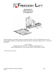
TRACKER USER’S MANUAL These instructions are provided to assist you in using the Tracker power chair/scooter lift. If you require further assistance, our trained staff is ready to provide you with quick, efficient service. Call our toll-free number: 1-800-755-2856 Monday thru Friday, 8:00 AM – 6:00 PM (Except holidays) E.S.T Before calling please have your customer number or order number available. 2003 Freedom Lift Corporation FL-1027-W 4/29/05 Page 1 TABLE OF CONTENTS SAFETY FIRST ……………………………………………………………………………………………………. 3 NOTES ABOUT POWERING THE TRACKER LIFT ………………………………………………………. 5 POWERING THE LIFT WITH THE “MOBILE POWER” BATTERY PACK …………………….. 5 RECHARGING THE BATTERY PACK ……………………………………..………………………… 6 HARD WIRED LIFT ………………………………….. ..…………..………..……...………………… 7 USING THE LIFT ……………………………………………………………………………………… 8 LOADING THE POWER CHAIR/SCOOTER ………………………………………………………….. 9 STRAPPING THE POWER CHAIR/SCOOTER TO THE PLATFORM …………………………….. 10 OPTIONAL: DOCK-N-LOCK USER INSTRUCTIONS……………………………………………….11 LIFTING THE POWER CHAIR/SCOOTER INTO THE VEHICLE …………………………..…….. 13 UNLOADING THE POWER CHAIR/SCOOTER ……………………………………………...…..… 14 STORING THE PLATFORM WITHOUT POWER CHAIR/SCOOTER ………………………..…… 14 CONFIRMING HOME POSITION AND LOCKING PIN ALIGNMENT …………………...……… 14 EMERGENCY STOW-AWAY ……………………………………………………………………………..…….. 15 EMERGENCY MANUAL LIFT PROCEDURE ….……………………………………………………………….16 MAINTAINING THE LIFT ……………………………………………………………………………………….18 TROUBLESHOOTING CHART ………………………………………………………………………………..…. 18 INSPECTION OF LIFT ALIGNMENT ………………………………………………..…………………...……… 19 FUSE FOR THE RF REMOTE CONTROL UNIT ……………………………………………………..………… 20 FOR YOUR RECORDS NAME OF INSTALLER_____________________________SALESPERSON______________________________________ ADDRESS________________________________________TELEPHONE________________________________________ PURCHASE DATE_________________________________LIFT SERIAL #______________________________________ CUSTOMER #_____________________________________ORDER #___________________________________________ A GUARANTEED “LIFT” AT YOUR FINGERTIPS FL-1027-W 4/29/05 Page 2 SAFETY FIRST 1. The power chair must have the brake engaged and be securely attached to the lift during transport. The straps, when properly adjusted and maintained, are intended to constrain the power chair or scooter. The straps should be checked to make certain they are in good condition before each use. WARNING: FAILURE TO ENGAGE THE BRAKE AND SECURELY STRAP THE POWER CHAIR/SCOOTER TO THE LIFT DURING TRANSPORT COULD RESULT IN SERIOUS PERSONAL INJURY OR DAMAGE TO THE LIFT, THE POWER CHAIR, AND VEHICLES. 2. After the Power Chair/Scooter has been lifted into the vehicle, turn the control cut-off switch off. This will prevent inadvertent operation of the lift by remote control and/or hand held pendant. Remember for the control cut-off switch – “RED IS ON.” ALWAYS PUSH THE POWER CUT-OFF SWITCH TO THE OFF POSITION WHEN NOT OPERATING THE LIFT. 3. The Tracker is equipped with a 30 AMP self-resetting circuit breaker on the wire harness. The circuit breaker is located in the vehicle near the battery end of the power wire harness. The circuit breaker protects the lift against excessive current draw. The circuit breaker is self-resetting. If the circuit breaker continues to trip, have the unit inspected by the installer or by an authorized service center to troubleshoot and correct the problem. WARNING: DO NOT ATTEMPT TO BYPASS THE CIRCUIT BREAKER AS THIS MAY CAUSE SERIOUS DAMAGE TO THE LIFT AND/OR CAUSE A FIRE. 4. The Tracker lift has a maximum weight lifting limit of 350 pounds. WARNING: DO NOT EXCEED THE MAXIMUM CAPACITY OF LIFT OR DAMAGE TO THE LIFT AND/OR SERIOUS INJURIES MAY OCCUR. Note: Most power chairs and scooters do not exceed 350 pounds unless larger batteries (longer range batteries greater than 33 amps each) are installed. If you have any questions on the weight of your scooter or power chair, please contact your lift installer or scooter manufacturer. FL-1027-W 4/29/05 Page 3 5. The Tracker lift has been designed to lift power chairs and scooters. It has not been designed or intended to lift any other object. Lifting people or objects other than power chairs or scooters may be dangerous. 6. Keep the area underneath of the lift clear at all times (i.e. objects, pets, people, etc.). FL-1027-W 4/29/05 Page 4 NOTES ABOUT POWERING THE TRACKER LIFT There are two methods for powering the lift: • • Using the “Mobile Power” Battery Pack or Hard Wiring the lift to the vehicle’s battery Note: The lift may be hard wired to the vehicle’s battery, and use a “Mobile Power” battery pack for back-up power. POWERING THE LIFT WITH THE “MOBILE POWER” BATTERY PACK Wiring the “Mobile Power” battery pack to the Tracker is as simple as lowering the pack onto the tabs on the battery bracket, and plugging in the connector from the battery pack to the Tracker. The battery pack slides onto the tabs on the battery bracket. Make certain the side labeled “This Side Toward Lift” is facing the lift. Fasten the battery pack to the bracket using the Velcro strap provided. Location of 12 Volt DC Connector Plug the cable from the battery pack into the 12 V DC connector on the trolley assembly. FL-1027-W 4/29/05 Page 5 RECHARGING THE BATTERY PACK Use only Freedom Lift approved charging accessories for charging your “Mobile Power” Battery Pack. Charging the Battery Pack: If you have ordered a Tracker with the “Mobile Power” Battery Option, your Tracker was shipped with a 2A charger, 110 volts AC input, 12 volts DC output. Charge the Battery Pack for 24 hours prior to initial use. Charge the battery until the LED is green. You may leave the battery switched on during charging so that you may monitor the LED color. FL-1027-W 4/29/05 Page 6 HARD WIRED LIFT Your lift may be hard wired using a wire harness that runs from the battery’s terminals, through the transporting vehicle’s fire wall, to the cargo area where the lift is located. Take care not to pinch or nick the wire. CONNECTING THE POWER FROM THE WIRE HARNESS TO THE TRACKER: Plug the 12 VDC connector w/locking tab from either the “Mobile Power” rechargeable battery pack or from the hard-wired connection, into the relay box on the lift. Make sure the lift’s control cut-off switch is turned on before operating the lift; you will see the RED portion of the switch when it is ON. “RED IS ON” ALWAYS PUSH THE POWER CUT-OFF SWITCH TO THE OFF POSITION WHEN NOT OPERATING THE LIFT. FL-1027-W 4/29/05 Page 7 USING THE LIFT Make sure that all objects are removed from the landing area below the platform Turn the control cut-off switch to ON (“RED IS ON”) Location of the Control Cut-Off Switch and Pendant Connector Starting with the platform inside the vehicle, depress the OUT portion of the rocker switch on the pendant. Wired Pendant FL-1027-W 4/29/05 Key Chain Remote Page 8 The platform will slowly come out of the vehicle and lower to the ground. When the platform contacts the ground, release the rocker switch. Platform resting properly on level ground If the platform does not rest flat on level ground, contact the installer and have the installer adjust the set screws in the platform frame. LOADING THE POWER CHAIR/SCOOTER Slowly & carefully drive your power chair/scooter straight onto the lift platform, front-end casters first, making sure that the wheels are centered on the platform. You may find it easier to stand alongside the scooter while slowly maneuvering the scooter onto and off of the platform. This method will also help if the power chair’s batteries are weak and there is insufficient power to drive onto the platform. Exit the power chair. Remove and store any loose objects. Be sure the batteries on the power chair/scooter are securely strapped in place. Fold down the seat back of your power chair / scooter if necessary so that it will fit into the cargo area of your vehicle. Power Chair on platform; seat back folded down to fit into vehicle FL-1027-W 4/29/05 Page 9 STRAPPING THE POWER CHAIR/SCOOTER TO THE PLATFORM Buckle (above) Latch Plate & Adjustable Strap (below) Strap your chair to the platform: Connect the seat belt strap across the seat of your power chair and pull the strap to tighten the strap securely across the seat. Examples of a Power Chair (left) and a Scooter (right) strapped to the platform WARNING: FAILURE TO SECURELY ATTACH THE POWER CHAIR TO THE LIFT DURING TRANSPORT COULD RESULT IN SERIOUS PERSONAL INJURY OR DAMAGE TO THE LIFT, THE POWER CHAIR, AND VEHICLES. Your dealer/installer can help determine the best location of the straps to suit your power chair/scooter. FL-1027-W 4/29/05 Page 10 OPTIONAL: DOCK-N-LOCK USER INSTRUCTIONS Introduction: The Dock-N-Lock system is an Electronic-docking device designed to eliminate straps and other manual locking devices for scooters and power chairs. How to Use: Docking your scooter or power chair for transportation 1. Operate the lift so the platform is on the ground ready to drive the scooter or power chair on. Figure 1. Figure 1 2. Drive your scooter or power chair forward onto the platform with the installed Dock-N-Lock system and proper brackets mounted on the bottom of he scooter or power chair. Figure 2 3. The scooter or power chair will lock itself into the unit. *IMPORTANT* The unit is locked in when the green pushbutton is lit up. The power chair is not docked until the light comes on. Figure 3 4. Get off the scooter or power chair and operate the lift back into the van for transportation. 1. 2. 3. 4. 5. Figure 3 Releasing your scooter or power chair for operation Operate the lift so the platform is on the ground ready to drive the scooter or power chair off. Drive scooter or power chair forward while locked in the Dock-N-Lock unit. (Locking jaws may be jammed from movement while driving) Push the green pushbutton one time to unlock the chair from the Dock-N-Lock. Figure 4. Drive the scooter or power chair off of the platform. Operate the lift back into the van for transportation. Push to release Figure 4 FL-1027-W 4/29/05 Page 11 Troubleshooting: 1. 2. Symptom Green light is not on Problem No Power to unit Scooter or power chair will not release Chair is not docked in the DockN-Lock Too much time to back off the unit. No Power to the unit No Power to the unit Locking jaws are jammed 3. Scooter or power chair will not dock 4. Lift is going in slower than normal. Green light is on, but will not release 5. Docking bracket is not aligned with the Dock-N-Lock. (Driving in at an angle) Insufficient Battery Voltage (Battery Pack only) Battery power is on, but the power switch on the unit is off. Solution Turn the Battery pack power on Back-up and drive into the Dock-N-Lock again Hit the green button again. (Unit will unlock for 8 seconds each time button is pushed) Turn the battery pack and main power switch on Use the manual release lever on the Dock-N-Lock unit. Figure 5 Move scooter or power chair forward while locked in the Dock-N-Lock unit. Then hit the green button again Drive straight into the Dock-NLock unit Recharge the Battery Pack Turn the switch “on” located on the Tracker. Manual release pin location Figure 5 FL-1027-W 4/29/05 Page 12 LIFTING THE POWER CHAIR / SCOOTER INTO THE VEHICLE Depress the IN portion of the rocker switch on the control pendant. The Tracker will lift your power chair/scooter into the vehicle. Power Chair lifted into the vehicle’s cargo area CAUTION: MANY POWER CHAIRS HAVE CONTROLS AND/ OR A JOYSTICK MOUNTED TO ONE OF THE ARMS. BEFORE CLOSING THE CARGO AREA DOOR, MAKE CERTAIN THE CONTROL ARM ON YOUR POWER CHAIR IS FOLDED/ROTATED OUT OF THE WAY OF THE CARGO DOOR TO AVOID DAMAGE TO THE CONTROL ARM/JOYSTICK OR YOUR VEHICLE. Joystick on control arm folded inward to avoid contact with cargo door After the Power Chair/Scooter has been lifted into the vehicle, turn the control cut-off switch off. This will prevent inadvertent operation of the lift by remote control and/or hand held pendant. Remember for the control cut-off switch – “Red is ON.” ALWAYS PUSH THE POWER CUT-OFF SWITCH TO THE OFF POSITION WHEN NOT OPERATING THE LIFT. FL-1027-W 4/29/05 Page 13 UNLOADING THE POWER CHAIR/SCOOTER Simply follow the LOADING process in reverse sequence. STORING PLATFORM WITHOUT POWER CHAIR/SCOOTER To store the platform, lay the straps across the platform, as shown. It is important to keep the straps out of the way of the tracks in the trolley assembly. Depress the IN portion of the rocker switch on the control pendant. The Tracker will lift the empty platform (with straps) into the vehicle. CONFIRMING HOME POSITION AND LOCKING PIN ALIGNMENT The Tracker is in its home position when the horizontal motion is completed. When the Tracker is in its home position, it is important that the alignment pins are captured in the holes in the front plate/high threshold plate (see figure below) If the pins are not captured in the holes, have your dealer/installer adjust your Tracker lift. WARNING: THE ALIGNMENT PINS SECURE THE PLATFORM, AND TOGETHER WITH THE STRAPS, SECURE THE POWER CHAIR/SCOOTER TO THE TROLLEY ASSEMBLY DURING TRANSPORT. AN UNSECURED POWER CHAIR/SCOOTER CAN CAUSE SERIOUS INJURIES. FL-1027-W 4/29/05 Page 14 EMERGENCY STOW-AWAY If the Tracker has completed lifting your power chair/scooter, but will not move into the car, you can push it into the car after pulling the release pin. WARNING: After pushing the Platform Assembly into your car, you must put the release pin back into place, or the Platform Assembly could slide outward during transport. The release pin passes through a slot in the lead screw. Push/pull the Platform Assembly a few inches to rotate the screw and align the slot so the pin will pass through it. AFTER PERFORMING THE EMERGENCY STOW-AWAY PROCEDURE - CONTACT YOUR DEALER/INSTALLER IMMEDIATELY TO INSPECT AND REPAIR YOUR TRACKER LIFT. FL-1027-W 4/29/05 Page 15 EMERGENCY MANUAL LIFT PROCEDURE The Tracker Lift is equipped with a manual emergency lift and stow feature in the event of an electrical or mechanical failure to get you r chair safely back into your vehicle and enable you to proceed to a dealer nearest you. The following procedure can be performed while the power chair is safely mounted to the platform. CAUTION: TURN POWER OFF BEFORE INSERTING MANUAL HEX TOOL INTO MOTOR. If the platform is partially or fully lowered to the ground you will need to use the 5/16” hex wrench emergency tool that is supplied with your lift. Please keep this tool in the vehicle at all time in the event that and manual lift operation is necessary. • • • • PRY OUT PLASTIC PLUG IN BASE OF LIFT ACTUATOR MOTOR. VIEW “A”. INSERT THE HEX TOOL INTO THE END OF THE MOTOR HOUSING. VIEW “B”. ROTATE TOOL COUNTERCLOCKWISE TO RAISE PLATFORM AND CLOCKWISE TO LOWER.( IT WILL TAKE APPROX 15 FULL TURNS TO RAISE 1/8 INCH.) TO RAISE OR LOWER PLATFORM FASTER, USE A POWER DRILL AND INSERT THE STRAIGHT HEX BIT. VIEW “C”. VIEW “A” VIEW “B” VIEW “C” FL-1027-W 4/29/05 Page 16 Once the platform is lifted to its full raised position follow the next steps to push the Tracker back into the vehicle. • • • • FROM INSIDE THE VEHICLE LOCATE THE PULL PIN AT THE END OF THE TRACKER. VIEW “D”. PULL THE PIN OUT BY PULLING STRAIGHT UP. STAND IN FRONT OF THE PLATFORM AND POWER CHAIR AND GIVE A HARD QUICK PUSH TO THE POWER CHAIR OR THE TRACKER PLATFORM WHICH EVER IS CONVENIENT. VIEW “E” ONCE YOU FEEL THE TROLLEY MOVING BACK CONTINUE TO STEADILY PUSH THE PLATFORM BACK INTO THE VEHICLE. VIEW “D” VIEW “E” WARNING: After pushing the Platform Assembly into your car, you must put the release pin back into place, or the Platform Assembly could slide outward during transport. AFTER PERFORMING THE EMERGENCY STOW-AWAY PROCEDURE - CONTACT YOUR DEALER/INSTALLER IMMEDIATELY TO INSPECT AND REPAIR YOUR TRACKER LIFT. FL-1027-W 4/29/05 Page 17 MAINTAINING THE LIFT WITH EACH USE: • KEEP THE TRACKS CLEAR OF FOREIGN OBJECTS. Even small stones/gravel inside the tracks can interfere or stop the operation of your Tracker. • Inspect the straps for wear or fraying. • Inspect the side-to-side clearances and over the bumper & threshold clearances (page 15). MONTHLY: • Check all mounting hardware for tightness and signs of wear. TWICE A YEAR: • Lubricate the lead screw with a small amount of wheel bearing grease. Lubricate all bearing points and moving parts using wheel-bearing grease. TROUBLESHOOTING CHART SYMPTOM Lift does not work Lift runs slowly POSSIBLE CAUSE Control cut-off switch is off. Power cord is unplugged from lift. Plug the power cord into Tracker, see page 5 Vehicle battery not connected or is dead. Mobile Power battery pack is weak or “dead” Pendant not plugged in Check the battery connections; charge the battery. Trolley not moving on tracks Foreign objects in tracks; clean out the tracks RF remote batteries are weak/”dead” RF fuse blown Replace batteries in RF remote Try the hand held pendant Inspect RF fuse, replace if needed, see page 16 Weak vehicle battery or Mobile Power battery pack. Charge Mobile Power battery pack Charge vehicle’s battery or run vehicle to charge it. Load is too heavy. Only lift power chairs under 350 pounds. Remove any heavy personal items stored on Power Chair/Scooter. Re-adjust the strap. Power chair too loose or too tight on the lift Improperly adjusted strap Loud mechanical clicking sound after the lifting is complete Actuator (electric cylinder) is clutching out Misalignment of lift, platform not clearing bumper, rubbing into vehicle Alignment hardware not tightened. Improper alignment during installation. FL-1027-W 4/29/05 SOLUTION Turn the switch on. “RED IS ON”, see page 3 Check LED on Mobile Power battery pack; charge if it is red, see page 6. Plug pendant in, see page 8 See if problem occurs without Power Chair/Scooter on the platform. Have the dealer inspect the “boom mounted limit switch” and adjust the contact screw. Inspect the lift alignment, see page 15 Have the dealer inspect and adjust the lift alignment. Page 18 INSPECTION OF THE LIFT ALIGNMENT Operate the Tracker without a load and check the clearance of the platform over the bumper and threshold of the vehicle. Check the side-to-side clearances Repeat these clearance checks with your power chair/scooter on the platform & strapped down. IF THE LIFT IS OUT OF ADJUSTMENT, CONTACT YOUR DEALER/INSTALLER TO CORRECT THE ADJUSTMENT. FL-1027-W 4/29/05 Page 19 FUSE FOR THE RF REMOTE CONTROL CIRCUIT If the Remote Control is not working, check the fuse to see if it is blown. Replace the fuse if necessary. If the Remote Control unit still does not function, there may be another problem with the Tracker - check the operation of the Tracker using the hand held pendant. FL-1027-W 4/29/05 Page 20