1
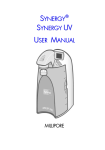
USER’S MANUAL FOR F&Q SUBMERSIBLE SEWAGE PUMPS CFW40 / CFW50 / CFW50V SERIES Description
F&Q submersible sewage pumps are self-contained and recommended for use
in a sump or basin. The sump or basin shall be vented in accordance with local
plumbing codes. Designed to pump effluent or wastewater, non-explosive and
noncorrosive liquids, and shall NOT be installed in locations classified as
hazardous in accordance with the United States National Electrical Code
(NEC), ANSI/NFPA 70. Never install the pump in a trench, ditch, or hole with a
dirt bottom; the legs will sink into the dirt and the suction will become plugged.
Specifications
TEMPERATURE..............104°F (40°C) Continuous
UPPER BEARING...........Single row, ball design oil lubrication,
IMPELLER..................... CFW40/50: 2 Vane, open
radial load
CFW50V: 10 Vane, Vortex
LOWER BEARING..........Single row, ball design, oil lubrication,
SOLIDS HANDLING.......2" (51mm) spherical
radial & thrust load
PAINT............................ Air dry enamel
MOTOR......................... NEMA L, torque curve, oil-filled,
SEAL............................. Single mechanical, Silicon Carbide,
squirrel cage induction, Class B insulation
oil-filled reservoir, 300 series Stainless Steel Parts
SINGLE PHASE.................. Permanent Split Capacitor (PSC)
CABLE ENTRY............... 20 ft. (6 m) quick disconnect cord,
Includes Thermal Overload Protection in motor
with plug on 120 & 240 volt, 1 phase, pressure grommet
CONSTRUCTION MATERIAL……. Class 30 cast iron for motor
for
sealing and strain relief.
house, Seal Plate and impeller
OPTIONAL.... 20 ft float switch with piggy-back plug
F&Q Pumps, Inc 10617 E. Rush Street S. El Monte, CA 91733
Phone: 626-455-0884 Fax: 626-448-9462
www.fandqpumps.com
1 Motor & Electrical
Models
Hp
Volt/Ph
Hz
Rpm
NEMA
Full
Locked
Cord
Cord
Cord O.D.
Start Code
Load Amps
Rotor Amps
Size
Type
Inches (mm)
CFW40A
4/10
115/1
60
1750
C
12.0
19.0
14/3
SJTOW
0.375 (9.5)
CFW40M
4/10
115/1
60
1750
C
12.0
19.0
14/3
SJTOW
0.375 (9.5)
CFW50A
1/2
115/1
60
1750
A
12.0
26.0
14/3
SJTOW
0.375 (9.5)
CFW50M
1/2
115/1
60
1750
A
12.0
26.0
14/3
SJTOW
0.375 (9.5)
CFW50VA
1/2
115/1
60
1750
A
12.0
26.0
14/3
SJTOW
0.375 (9.5)
CFW50VM
1/2
115/1
60
1750
A
12.0
26.0
14/3
SJTOW
0.375 (9.5)
CFW502VA
1/2
230/1
60
1750
A
5.5
13.0
14/3
SJTOW
0.375 (9.5)
CFW502VM
1/2
230/1
60
1750
A
5.5
13.0
14/3
SJTOW
0.375 (9.5)
Performance
Models
Hp
Speed
Disch. NPT
Gal./Min @ Total Head in Feet
Shut off
0 Ft
5 Ft
10 Ft
15 Ft
20 Ft
25 Ft
CFW40A
4/10
1750
2” (51mm)
135
125
110
85
50
5
25.5
CFW40M
4/10
1750
2” (51mm)
135
125
110
85
50
5
25.5
CFW50A
1/2
1750
2” (51mm)
140
130
115
90
55
25
CFW50M
1/2
1750
2” (51mm)
140
130
115
90
55
25
CFW50VA
1/2
1750
2” (51mm)
130
120
95
65
23
23
CFW50VM
1/2
1750
2” (51mm)
130
120
95
65
23
23
CFW502VA
1/2
1750
2” (51mm)
130
120
95
65
23
23
CFW502VM
1/2
1750
2” (51mm)
130
120
95
65
23
23
Dimensions
2 General Safety Information
Please read this before installing
caustic,etc.) unless the pump is
power source before handling
or operating pump, this information
specifically designed and
or servicing.
is provided for SAFETY and to
designated to handle them.
9. Any wiring of pumps should be
PREVENT EQUIPMENT
3. Make sure lifting handles are
performed by a qualified
PROBLEMS. To help recognize
securely fastened each time
electrician.
this information, observe the
before lifting.
following symbols:
4. Do not lift pump by the power
NOTE: Indicates special
cord.
operate a pump with a power
instructions which are important
5. Do not exceed manufacturer’s
cord that has frayed or brittle
but not related to hazards.
recommendation for maximum
insulation.
IMPORTANT: Indicates factors
performance, as this could cause
10. Cable should be protected at
concerned with assembly,
the motor to overheat.
all times to avoid punctures, cuts,
installation, operation, or
6. Secure the pump in its operating
bruises, and abrasions – inspect
maintenance which could result in
position so it cannot tip over, fall,
frequently.
damage to the machine or
or slide.
equipment if ignored.
7. Keep hands and feet away from
1. Most accidents can be avoided
impeller when power is connected.
by using COMMON SENSE.
Never
handle connected power cords
with wet hands. Never operate a
Submersible
Do not wear
Never
120 volt pump with a plug-in
pumps are not approved for use
type power cord without a
loose clothing that may become
in swimming pools, recreational
ground fault circuit interrupter
entangled in the impeller or
water installations, decorative
11.
other moving parts.
fountains, or any installation
strain relief. Do not connect
Always wear appropriate safety
where human contact with the
conduit to pump.
gear, such as safety glasses,
pumped fluid is common.
when working on the pump or
8. Operation against a closed
piping.
discharge valve will cause
risk of electrical shock, all
premature bearing and seal failure
wiring and junction connections
on any pump.
should be made per the United
Pumps build
To reduce
States National Electric Code
up heat and pressure during
operation. Allow time for pumps
Do not remove cord and
To reduce
(NEC), or the Canadian
to cool before handling or
risk of electrical shock, pump
Electrical Code (CEC) and
servicing.
must be properly grounded in
applicable state or province and
2. Only qualified personnel should
accordance with the United
local codes. Requirements may
install, operate, and repair pump.
States National Electric Code
vary depending on usage and
(NEC), or the Canadian
location. See wiring diagrams in
Keep clear of
Electrical Code (CEC) and
manual.
suction and discharge openings.
all applicable state, and local
F&Q Pumps, Inc is not responsible
Do not insert fingers in pump
codes and ordinances.
for losses, injury, or death resulting
from a failure to observe these
with power connected.
To reduce
Do not pump
Hazardous materials (flammable,
risk of electrical shock, always
safety precautions, misuse or
abuse of pumps or equipment.
disconnect the pump from the
3 Unpacking
installed and tested before the
system flow during pump or check
Upon receiving the pump, it should
long term storage begins, such
valve servicing.
be inspected for damage or
installation will be allowed
LIQUID LEVEL CONTROL
shortages. If damage has occurred,
provided:
Figure 2 shows a typical
file a claim immediately with the
1. The pump is not installed under
installation for any submersible
carrier that delivered the pump. If
water for more than one (1) month.
pump using a level control
the manual is removed from the
2. Immediately upon satisfactory
mounted to the discharge piping
packaging, do not lose or
completion of the test, the pump is
with a piggy-back plug.
misplace.
removed, thoroughly dried,
Storage
repacked in the original shipping
Short Term - Pumps are
container, and placed in a
manufactured for efficient
temperature controlled storage
performance following short
area.
inoperative periods in storage.
Installation
For best results, pumps can be
SUBMERGENCE
retained in storage, as factory
It is recommended that the pump
assembled, in a dry atmosphere
be operated in the submerged
with constant temperatures for up
condition and the sump liquid level
to six (6) months.
should never be less than “A”
Long Term - For storage of six (6)
dimension in Figure 1.
months, to twenty-four (24)
months, the units should be stored
in a temperature controlled area, a
roofed-over walled enclosure that
Figure 3 shows a typical
provides protection from the
connection for 1 phase 120V
elements (rain, snow, wind-blown
pumps with a piggy-back plug, for
dust, etc.), and whose temperature
manual and automatic operations.
can be maintained between +40° F
and +120° F. If extended high
humidity is expected to be a
problem, all exposed parts should
be inspected before storage and
all surfaces that have the paint
FIGURE 1
scratched, damaged, or worn
DISCHARGE
should be recoated with a water
Discharge piping should be as
base, air dry enamel paint. All
short as possible. Both a check
surfaces should then be sprayed
valve and a shut-off valve are
with a rust-inhibiting oil.
recommended for each pump
Pump should be stored in its
being used. The check valve
ELECTRICAL CONNECTIONS
original shipping container. On
is used to prevent backflow into
An acceptable motor control
initial start up, rotate impeller by
the sump. Excessive backflow can
switch shall be provided at the
hand to assure seal and impeller
cause flooding and/or damage to
time of installation.
rotate freely.
the pump.
Power Cable - The cord assembly
If it is required that the pump be
The shut-off valve is used to stop
mounted to the pump must not be
4 modified in any way except for
Before operating pump, check to
identification plate and record at
shortening to a specific application.
make sure that the voltage and
the end of the manual for future
Any splice between the pump and
phase information stamped on the
reference.
the control panel must be made in
pump’s identification plate
INSULATION TEST
accordance with all applicable
matches the available power.
Before the pump is put into service,
electric codes. It is recommended
CHECK PUMP ROTATION
an insulation (megger) test should
that a junction box, if used, be
Before putting pump into service
be performed on it. The ohm
mounted outside the sump or be of
for the first time, the motor rotation
values as well as the volts and
at least NEMA 4 construction if
must be checked. Improper motor
amps should be recorded.
located within the wet well. Do not
rotation can result in poor pump
PUMP-DOWN TEST
use the power cable to lift pump.
performance and can damage the
After the pump has been properly
NOTE: The white wire is NOT a
motor and/or pump. To check the
wired and lowered into the basin,
neutral or ground lead, but a
rotation, suspend the pump freely,
sump, or lift station, it is advisable
power carrying conductor.
momentarily apply power and
to check the system by filling with
observe the “kickback.” “Kickback”
liquid and allowing the pump to
should always be in a counter
operate through it’s pumping cycle.
electric shock. Do not remove
clockwise direction as viewed from
The time needed to empty the
cord and/or strain relief. Do not
the top of the pump (“kickback”
system, or pump down time,
connect conduit to pump.
is always opposite to impeller
should be recorded.
Wire Size
rotation).
Consult a qualified electrician for
“Rotation” and “kickback” direction
Maintenance
proper wire size. See table on
is noted on the pump motor
As the motor is oil filled, no
page 2 for electrical information.
housing.
lubrication or other maintenance is
Pre-operation
IDENTIFICATION PLATE
required.
CHECK VOLTAGE AND PHASE
Note the numbers on the pump’s
Risk of
Troubleshooting Chart
Always disconnect the pump from the electrical power source before handling. If the system
fails to operate properly, carefully read instructions and perform maintenance recommendations. If operating
problems persist, the following chart may be of assistance in identifying and correcting them.
NOTE: Not all problems and corrections will apply to each pump model.
Symptom
Possible Cause (s)
Corrective Action
Pump will not run
1. Poor electrical connection, blown fuse,
1. Check all electrical connections for security. Have
tripped breaker, or other interruption of
electrician measure current in motor leads. If current is within
power; improper power supply
± 20% of locked rotor Amps, impeller is probably locked. If
current is 0, overload may be tripped. Remove power, allow
pump to cool, then recheck current
2. Switch will not activate pump or is
2. Disconnect level control. Set ohmmeter for a low range,
defective
such as 100 ohms full scale and connect to level control
leads. Actuate level control manually and check to see that
ohmmeter shows zero ohms for closed switch and full scale
for open switch (Float Switch)
5 Troubleshooting Chart (Continued)Sym
ptomSymptom Possible Cause (s) Corrective Action
Symptom
Possible Cause (s)
Corrective Action
Pump will not run
3. Motor or switch inoperative
3. Go to manual operation of pump
4. Float movement restricted
4. Reposition pump or clean basin as required to provide
adequate clearance for float
5. Defective motor
5. Check winding insulation (Megger Test) and winding
resistance. If check is outside of range, dry and recheck. If
still defective, replace per service instructions
6. Insufficient liquid level
6. Make sure liquid level is at least equal to
suggested turn-on point
Pump hums but doesn’t
1. Incorrect voltage
1. Check all electrical connections for security
run
2. Impeller jammed or loose on shaft,
2. Check impeller for freedom of operation, security, and
worn, or damaged, impeller cavity or
condition. Clean impeller cavity and inlet of any obstruction
inlet plugged
Pump delivers insufficient
1. Incorrect voltage
1. Check all electrical connections for security.
capacity
2. Excessive inflow or pump not properly
2. Recheck all sizing calculations to determine
sized for application
proper pump size
3. Discharge restricted
3. Check discharge line for restrictions, including ice. If line
passes through or into cold areas
4. Check valve stuck closed or installed
4. Remove and examine check valve for proper
backwards
installation and freedom of operation
5. Shut-off valve closed
5. Open valve
6. Impeller jammed or loose on shaft, worn
6. Check impeller for freedom of operation, security, and
or damaged, impeller cavity or inlet plugged
condition. Clean impeller cavity and inlet of any obstruction
7. Pump may be airlocked
7. Loosen union slightly to allow trapped air to escape. Verify
that turn-off level of switch is set so that impeller cavity is
always flooded. Clean vent hole
8. Pump running backwards
8. Check rotation. If power supply is three phase,
reverse any two of three power supply leads to
ensure proper impeller rotation
Pump operates noisily or
1. Worn bearings, motor shaft bent
vibrates excessively
1. Check winding insulation (Megger Test) and winding
resistance. If check is outside of range, dry and recheck. If
still defective, replace per service instructions
2. Debris in impeller cavity or broken
2. Check impeller for freedom of operation, security, and
impeller
condition. Clean impeller cavity and inlet of any obstruction
3. Pump running backwards
3. Check rotation. If power supply is three phase, reverse any
two of three power supply leads to ensure proper impeller
rotation
4. Piping attachments to building structure
4. Replace portion of discharge pipe with flexible
too rigid or too loose
connector
Possible Cause (s) Corrective Action
6