1
XL-ICA-311
RTSP DUAL Streaming
IP Camera
User Manual
Chapter 1. General Introduction....................................................................................................................... 3
1.1 Product Package Contents.....................................................................................................................................3
1.2 System Requirements of IE browser ....................................................................................................................4
1.3 Outlooks and Connection ......................................................................................................................................5
Mounting .......................................................................................................................................................................7
2.1 Foreword ............................................................................................................................................................... 11
2.2 The first time to login and setup IP camera .......................................................................................................12
Chapter 3. Advanced Configuration of IE ...................................................................................................... 19
3.1 Foreword ...............................................................................................................................................................19
3.2 IE Function Pages.................................................................................................................................................19
Chapter 4. Install Client Software................................................................................................................... 54
4.1 Foreword ...............................................................................................................................................................54
4.2 Installation Instruction ........................................................................................................................................55
Chapter 5. Client Software Functions ............................................................................................................ 60
5.1 Foreword ...............................................................................................................................................................60
5.2 Brief Introduction of Client software interface .................................................................................................60
5.3 Advanced Introduction of Client software functions ........................................................................................65
5.4 The Backup Utility of Client software ................................................................................................................81
5.5 The Database Compact of Client software.........................................................................................................92
5.6 The Lost File Recovery of Client software .........................................................................................................94
5.7 The Set IP Tool software ......................................................................................................................................98
Appendix A: Reset and Factory Default Value ............................................................................................. 101
Appendix B: Network problematic Utilities ...................................................................................................111
Appendix C: Internet Explore Security Settings .......................................................................................... 113
Appendix D: Frequently Asked Questions .................................................................................................... 114
IP Camera Features.................................................................................................................................................. 114
IP Camera Installation ............................................................................................................................................. 115
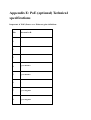
Appendix E: PoE (optional) Technical specifications.................................................................................. 123
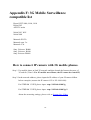
Appendix F: 3G Mobile Surveillance compatible list................................................................................... 124
How to connect IP camera with 3G mobile phones. ..............................................................................................124
Appendix G: Note of Network Ports and SD/USB compatible list............................................................... 125
2
Chapter 1. General Introduction
Thank you for purchasing XtendLan IP Camera. It is a versatile and high resolution image
solution for your office or home surveillance. It’s also a stand-alone camera system with a
built-in processor and web server that provides highest quality video and two-way audio.
This IP camera can be accessed remotely by cellular phones, and controlled from any PC &
Notebook over the Intranet or Internet via Microsoft IE browser or remote application
software.
The user-friendly installation procedure and intuitive web-based interface offer
easy integration with your LAN environment or Wi-Fi network.
of useful alarm tool to notice user at alarm situation.
It also comes with a lot
It’s a really good choice to build a
stable and remote surveillance system.
1.1 Product Package Contents
Before installation, please check your package contents to ensure that all items have
been included in product. If any of the listed items are missing, please contact your
reseller from where you purchased this product for assistance.
The package includes:
※ IP Camera device * 1
※ AC Power adapter * 1 (None for IP camera with PoE)
※ Installation CD * 1
If any of above items are missing, please contact your local reseller immediately.
3
1.2 System Requirements of IE browser
Local Area Network: 10Base-T Ethernet or 100BaseTX Fast Ethernet Wi-Fi Network:
IEEE 802.11 b/g
Configuration Environment of browser:
• ActiveX Enabled and Compliant Web Browser (recommended: Microsoft™ Internet
Explore 6.0 or later)
• CPU: Pentium IV, 1.8 GHz or above
• Memory Size: 512MB or above
• VGA card resolution: 1024*768 (recommended: Support Overlay function VGA
Card)
• OS: Windows™ 2000 SP4, XP SP2 and VISTA (32 bits) with DirectX9.0c or above
• Other suggestion requirement: CD-ROM.
Important! : Static IP address is not required to access camera from the Internet. If it is
dynamic IP obtained from your Internet service provider, then singing up
for a dynamic DNS (DDNS) service will make accessing form the Internet
much easier.
Singing up for a DDNS is easy and free of charge. For
more details of DDNS service providers please sees FAQ.
4
1.3 Outlooks and Connection
XL-ICA103 : Indoor fixed box IP Camera
Front:
Rear:
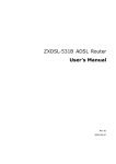
XL-ICA311 : Outdoor fixed IR IP Camera:
5
6
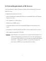
7
LAN (Internet or Intranet) RJ-45
Pin 1 Pin 2 Pin 3 Pin 4
OUT
OUT
1
IN
Power
Pin 5
Pin 6
Pin 7
Pin 8
Pin 9
Pin 10
RS485+
RS485-
RS485-
RS485+
RS232
RS232
(Rx)
(Rx)
(Tx)
(Tx)
(Rx-IN)
(Tx-IN)
GND
8
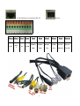
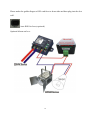
How to connect the cables with IP camera, please check below steps:
Step 1. Plug the Ethernet cable into the RJ-45 connector of the tail connectors as picture
shown.
Step 2. Plug the other end of the Ethernet cable into any available LAN port.
Typical
home router/gateway connection.
Step 3. Connect the power supply to the Power connector, and then plug the supply into
an available power outlet.
Caution 1: Make sure that you used correct power adapter for IP Camera. Using an
incorrect power adapter may damage the device.
Caution 2: If you’re using XL-ICA311-PoE (PoE IP camera), there’s no connection of
Power supply.
Side of IP camera: Only for OEM models
Adjust the level of Video Signal (H: High, L: Low)
AGC functions (switch down to enable [ON])
AES: Auto Electronic Shutter between 1/60(50) – 1/100000
BLC: White Balance (AUTO)
SD card slot
9
Please make the golden fingers of SD card face to down side and then plug into the slot
well.
Auto IRIS for Lens (optional)
Optional Alarm out box:
10
Chapter 2. Basic Introduction of IE
2.1 Foreword
For easy and convenient setup, we recommended to use Windows™ Internet Explorer
6.0 or above version at the first time to login and setup the IP camera. For IE of
Windows™ Vista OS, please refer to Internet Explorer Security Settings.
Please connect the power core with IP camera well and then use network cable to
connect IP camera with hub or switch hub directly. And please note that IP of PC should
be under the same network area which’s like: 192.168.0.xxx (except 192.168.0.100),
subnet: 255.255.255.0
The IP camera had a default IP was: 192.168.0.100
The default account name & password were: admin
Now, we can start to login and setup IP camera as below chapter.
Note! : At the first time to connect and setup the IP camera, we didn’t recommend to
connect with PC directly because the IP camera needs to download a MPEG-4
codec from Internet as below chapter. The PC will not be able to connect with
internet if only have one network card to connect with IP camera directly.
Install Mpg4DecodeSetup_v11.exe (in product CD), or click the
on CD MENU.
11
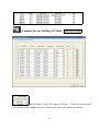
2.2 The first time to login and setup IP camera
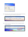
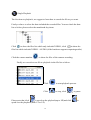
Step 1. Please use mouse to double-click the IE icon on desktop or quick launch bar.
12
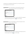
Step 2. After IE launch, please key-in the IP, 192.168.0.100 into the IP address blank as
below and then just press “ENTER” on keyboard.
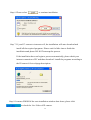
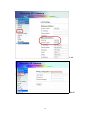
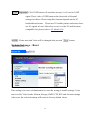
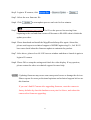
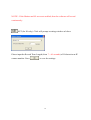
Step 3. The IE will require to the User Name and Password for login. Please input the
default Name and Password which both were: admin
They can be changed in IP camera’s configuration, please check System Set Account.
13
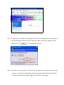
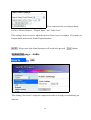
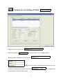
Step 4. After login, you’ll see a yellow bar upon the webpage, please do click the bar to
install ActiveX™ program or the IP camera cannot work well.
Step 5. After above, please click “Install ActiveX Control” item again to install the
program of IP camera.
14
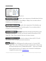
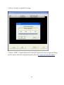
Step 6. Please select
to continue installation.
Step 7. If your PC connect to internet well, the installation will auto download and
install all the required programs. Please wait for little time to finish the
installation and please DO NOT interrupt the process.
If the installation have not begin to process automatically, please check your
internet connection of PC and then download / install the programs according to
the IP camera’s first webpage description.
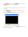
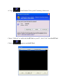
Step 8. It means FINISH if the auto-installation window shut down, please click
to check the Live Video of IP camera.
15
Step 9. At this time, sometimes the Windows™ firewall will popup the alert message to
ask for blocking. Please DO NOT block the traffic between IE and IP camera.
Please select
to continue the process.
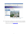
Step 10. Finally, we can see the Live Video from IP camera. If you cannot see the video,
may be caused by the Mpeg4DecodeSetup program didn’t install well. Please
download and install manually and then check the video again.
16
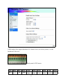
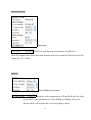
Step 11. If the video have no problem, users can setup the basic network configuration
which was like: LAN or PPPoE as below diagrams. For advanced setup of the
configurations, please refer to Net Setting - LAN.
17
LAN
PPPoE
18
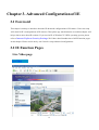
Chapter 3. Advanced Configuration of IE
3.1 Foreword
This chapter’s mainly to introduce about the IE advanced configurations of IP camera. Users can setup
ALL detail in IE’s configurations of IP cameras. Thus please pay much attention to read this chapter will
help to know more about IP cameras. If you use the IE of Windows™ VISTA operating system, please
refer to Internet Explorer Security Settings. We’ll have detail introduction of all IE function pages
in this chapter. Please read it one by one if need to setup advanced configurations.
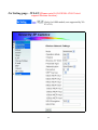
3.2 IE Function Pages
Live Video page
19
Live Video window:
Display OSD timer
Langage :
Multi-Language support .
Live Video configurations:
Users can adjust the brightness, saturation, contrast and hue values of live video.
To change the zoom’s value can enlarge or shrink the display size of live video window.
Reset to default values please refer to System Setting - Reset.
Two-ways Audio:
Click
to start sending the voice from PC sound card to IP camera’s speaker. Click
to turn-off the function.
20
Manual Recording & Snapshot:
Click
to record or snapshot, and then it will be saved in USB / SD storage.
About how to setup the storage, please refer to Storage Setting.
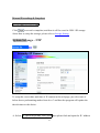
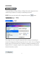
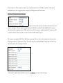
System Set page – NTP
To setup the correct date and time of IP camera in this webpage, just select one of
below three synchronizing modes from A to C and then the program will update the
date & timer to the choice.
A. Select
, then please find and input the IP / address
21
of NTP Server and select the correct Time Zone. The IP camera will auto update
with the NTP server to correct date and time.
B. Select
, then input the correct date and time manually. The IP
camera will change the time settings as user’s setup.
C. Select
, then click
to synchronize the date and time
with users’ PC timer.
NOTE! : Please be assured that you already pressed
to save the settings as
modified or the IP camera may not work well.
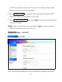
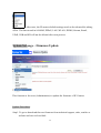
System Set page – Account
Users can modify the management of users’ accounts in this webpage. We provided
22
two different levels of Administrator and General User to be used. Please setup the
account management as below instruction.
Administrator level: This level had authority to setup and modify all settings of IP
cameras, thus please keep this account for higher securing.
Administrator Name was fixed『
, admin』, it cannot be modified. Please change the
password and confirm again, then click
to save the settings.
General User level: This level only had authority of video previewing, thus it cannot
modify any setting of IP camera.
User Name was fixed,『user』, it cannot be modified. Please change the password
and confirm again, then click
to save the settings.
23
NOTE! : Please be assured that you already pressed
to save the settings as
modified or you may not login to IP camera again.
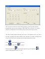
System Set page – Motion Setting
This IP camera supports Motion Detection on-line by itself and also can send alarm out
to notify users. About Motion Detect, users can find and modify the settings in this
24
webpage. We’ll introduce the detail as following.
Video Window:
This video window displays the camera’s video and the marked area of motion
detecting (if you haven’t arrange the mask area, enable MD will have the program to
detect ALL area).
In this picture, we already arranged 3*mask areas for
examples, so you can see 3*blue color masks on video window.
Mask Number:
If you want to setup the mask of motion detecting, please select the mask number
firstly and then use mouse (press left button) to drag on video window for drawing a
blue area. You’ll see a blue area after dragging (release mouse key) and marked to the
mask number on video window.
If you want to delete the mask, also please select the Mask Number firstly. Then click
to delete the mask.
Sensitivity:
25
Users can adjust the sensitivity of Motion Detection. Just need to use mouse to click
the slide bar and then move on the level between Low (L) and High (H) sensitivity.
Picture Capture:
Enable
to snapshot and then send to
(FTP) or
(Mail box) while motion being detected. About how to setup the FTP
and MAIL, please refer to Net Setting - Email and Net Setting - FTP
Use Direct Draw:
If you cannot see the video of Motion Detect video window, please
enable this item for more compatibility of VGA display.
NOTE! : Please note that Motion Detect function will work after pressed
save the settings.
System Set page – Alarm Setting
26
to
OEM models that support hardware I/O alarm device (see below picture, it’s the
hardware IO device).
Back-panel of IP Camera
Pin 1
Pin 2
Pin 3
Pin 4
Pin 5
Pin 6
Pin 7
OUT
OUT
1
IN
GND
RS485+
(Rx)
RS485(Rx)
RS485(Tx)
27
Pin 8
Pin 9
RS485+ RS232
(Tx)
(Rx-IN)
Pin 10
RS232
(Tx-IN)
We’ll introduce the detail of IO configuration as following.
Digital Input Alarm Settings:
This setting’s for uses to setup the Alarm Actions
(alarm picture to mail and FTP) as responding to the IO Input.
For example: We connected a sensor at IO INPUT and then enable (turn ON status) all
the Alarm Actions included Alarm Picture to Mail and FTP. When the
sensor detects something wrong, it will send the alarm having snapshot to
MAIL and FTP at the same time.
Video Loss Alarm Settings:
This setting’s for uses to setup the Alarm Actions
(alarm picture to mail) as responding to the Video Loss.
It means that IO Output will send alarm out and send message to mail box if the IP
camera lost the video signal.
Output Alarm Settings:
28
Users can select the one Output Alarm
Event in “Motion Detect”, “Digital Input” and “Video Loss”.
This setting’s also for uses to adjust the Action Time (from 1 second to 19 seconds) of
Output alarm and test the Alarm Output function.
NOTE! : Please note that Alarm functions will work after pressed
button.
System Set page – Audio
This setting’s for users to setup the compressed audio to storage or transmitting on
network.
29
Codec Settings:
To setup the Bitrate in 32kbps, 48kbps or 64kbps of the audio compression. Set to
smaller will get smaller size to storage or transmitting on network.
NOTE! : Please note that Audio will be changed after pressed
button.
System Set page – Video
This setting’s for users to setup the compressed video to storage or transmitting on
network. We designed two different setup modes for user’s choice. One is for Beginner
and the other is for Professional Users. Generally we strongly recommend to use the
Beginner Mode, it’s enough to setup the video compression. Below we will introduce
the detail about the two modes:
30
In Beginner mode, we can setup the main video stream simply.
Resolution: Select the resolution of video to QCIF, CIF or D1. This will have effect on
storage and network transmission.
Quality: Select the quality to Highest, Higher, Medium, Lower or Lowest. This will
also have effect on storage and network transmission.
Tip: The Quality is relate to the video’s Bit rate, the Bit rate will get higher if set to
better quality.
In Professional mode, we can setup dual-streaming (both of Main stream and sub
stream) and the video of 3GPP. Generally we take the Stream1 for main stream and the
Stream2 for sub stream.
Of course the two streams can be used to record, analyze, network surveillance or
re-process depends on users’ requests.
We’ll introduce one by one as following:
============================================================
31
Stream1 Settings:
Main Stream
Setup the video compression of Fixed Bit Rate (File Size)
to get stable video transmission. (From 48Kbps to 2Mbps) Users can choose either of
Fixed Bit rate or Fixed Quality to setup.
Setup the video compression of Fixed Quality to get
stable video quality (from Standard to Excellent quality). Users can choose either of
Fixed Bit rate or Fixed Quality to setup.
Important! Dual-Stream will share the Frame Rate to each
streaming. The Stream2 will not show-up if Stream1 shared Full Frame Rate (NTSC:
30fps, PAL: 25fps). Please setup the Frame rate for using or requests.
Select the resolution of video to QCIF, CIF or D1.
This will have effect on storage and network transmission.
Important! Click 3GPP button will send this stream (1 or 2) out for 3GPP
signal. There’s also a 3GPP button in Stream2 settings for choice. Please setup
this function depends on the 3G bandwidth and status.
Please use 3G mobile
phones and assure there are 3G signals at local. About the 3G mobile phone
compatible list, please refer to 3G Mobile List.
============================================================
32
Stream2 Settings:
Sub Stream
Enable to send Stream2 out in either for MPEG4 or
M-JPEG compression. Please note that Stream2 will not be enabled if Stream1 took full
frame rate (25 / 30 fps).
MPEG4:
Select MPEG4 for Stream2
Setup the video compression of Fixed Bit Rate (File Size)
to get stable video transmission. (From 48Kbps to 2Mbps) Users can
choose either of Fixed Bit rate or Fixed Quality to setup.
33
Setup the video compression of Fixed Quality to get
stable video quality. (From Standard to Excellent quality) Users can
choose either of Fixed Bit rate or Fixed Quality to setup.
Important! Dual-Stream will share the Frame Rate to each
streaming. For example, under NTSC (Full Frame rate: 30 fps), Stream2
can be set to 5fps if Stream1 set to 25fps.
Select the resolution of video to QCIF, CIF or D1.
This will have effect on storage and network transmission.
MJPEG:
Select JPEG for Stream2
Adjust the video quality of JPEG compression from 1 to 90.
The higher value will get higher quality and bigger file size.
Select the resolution of video to QCIF, CIF or D1.
This will have effect on storage and network transmission.
Important! Dual-Stream will share the Frame Rate to each
streaming. For example, under NTSC (Full Frame rate: 30 fps),
Stream2 can be set to 5fps if Stream1 set to 25fps.
34
Important! Click 3GPP button will send this stream (1 or 2) out for 3GPP
signal. There’s also a 3GPP button at the down side of Stream2
settings for choice. Please setup this function depends on the 3G
bandwidth and status.
Please use 3G mobile phones and assure there
are 3G signals at local. About how to use it or the 3G mobile phone
compatible list, please refer to 3G Mobile List.
NOTE! : Please note that Video will be changed after pressed
button.
System Set page – Reset
This setting is for users (Administrator) to reset the wrong or trouble settings. Users
can reset All, Video/Audio, Motion, Storage, SMTP, FTP, NTP and Account settings.
After reset, the selected settings will return to factory default values.
35
After reset, the IP camera default settings needs to be rebooted for taking
effect. The data stored in ALARM, PPPoE, LAN, WLAN, DDNS, Stream, Email,
UPnP, USB and SD will not be deleted after reset process.
System Set page – Firmware Update
This function is for users (Administrator) to update the firmware of IP Camera.
Update Procedures:
Step1. To get or download the new firmware from technical support, sales, retailer or
website and save in local disk.
36
→
Step2. Login to IP camera, click
→
Step3. Select the new firmware file
Step4. Click
to start update process and wait for few minutes.
Step5.
You’ll see the process bar moving from
beginning to the end and then screen will become to BLANK when it finish the
update procedure.
Step6. Please download and install the Mpg4DecodeSetup files again. About this,
please send request to technical support of MWR Engineering Co., Ltd. We’ll
have more detail about the firmware update to maintain the product.
Step7. After above, please close ALL IE browser window and then re-launch it again to
login to IP camera.
Step8. Please DO re-setup the settings and check the video display. If any question,
please contact the sales or technical support for more help.
NOTE! : Updating firmware may cause some unexpected errors or damage the devices.
Please request for more professional opinions and technical support before use
this function.
If you can’t find IP Camera after upgrading firmware, reset the camera to
factory defaults by short the hardware reset pins for 60secs, and reboot the
camera after firmware upgrading.
37
System Set page – Reboot
This function is for users (Administrator) reboot the IP Camera.
Just press the
button, then the IP camera will auto shut-down and initial
again by itself. The time length of Reboot procedure will be about 30 seconds.
When to use:
A. System upgrading, setup or reset errors.
B. No video display at local (not at remote side).
C. The device cannot connect to network (wire/wireless, PPPoE or DDNS fail).
D. Abnormal IP camera working.
E. Unstable IP camera working.
F. Unexpected system crash.
38
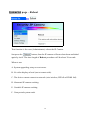
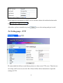
Net Setting page – PPPoE
This function’s for users (Administrator) to setup PPPoE dial network.
Please input the PPPoE information (User Name and password) to:
Click
to save the settings as modified.
Please disconnect the power cable of the IP camera and then re-connect IP camera to
PPPoE modem. The IP camera will connect to internet via PPPoE.
39
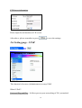
Net Setting page – DDNS
This function is for users (Administrator) to setup DDNS.
What’s DDNS?
Dynamic Domain Name Server: This function was used for dynamic IP users,
especially for xDSL internet connection. If you want to build a surveillance server on
internet but you have no physical IP address can be used for the server.
Now the IP camera can support the DDNS service of DynDNS.org and 3322.org
Please register an account at either of these two websites and then you will get the
DDNS service information.
Please input the DDNS service information:
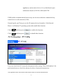
40
And then please enable
After above, please remember to press
to save the settings and get it work.
Before DDNS work, please assure that your PPPoE function of IP camera can dial-up
to internet without any problem.
Then please reboot IP camera and then wait it to initial the DDNS service.
If you want to see the video of the IP camera based on DDNS, just type the DDNS
Host Name in address and it will be transferred to the current IP of IP camera’s internet
connection.
41
Net Setting page – WLAN (Please note XL-ICA103/XL-ICA311 don’t
support Wireless function.)
(Only for OEM models, not supported by XLICA311)
42
The wireless of IP camera can be set to Infrastructure or Ad-Hoc mode of the basic
transmission. We suggested to setup by MIS person will be better.
Wireless Transmission settings:
Please select the correct wireless transmission of
above settings. Please note that Wireless AP SSID was NOT the SSID of IP camera,
this should be inputted the SSID of wireless AP or router, and then the IP camera will
connect to the wireless AP or router as the SSID name key-in.
IP camera supported WEP or WPA encryption. Please select the authentication mode
and input the key in below items. We DO NOT recommend that setup the wireless as
Open System for security reasons.
After above, please remember to press
to save the settings.
43
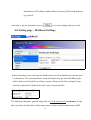
Net Setting page – LAN
In LAN settings, users can setup the DHCP or IP information of Ethernet (Wire) or
Wireless network connection. We recommended to setup this function by professional
MIS people will be better an IP surveillance system.
44
Wireless:
DHCP Client: Users can have a fix IP or DHCP for Wireless IP camera. Select
to enable DHCP client and then the IP camera will get an IP from the
router or server. If no, please turn it off
and then input the
information of IP Address, Subnet Mask and Gateway by yourself.
Ethernet: (Wired)
PPPoE: Users can setup PPPoE dial-up to internet. Select
to enable PPPoE
function, about the configuration, please refer to PPPoE.
DHCP Client: Users can have a fix IP or DHCP for Wireless IP camera. Select
to enable DHCP client and then the IP camera will get an IP from the
router or server. If no, please turn it off
45
and then input the
information of IP Address, Subnet Mask, Gateway, DNS and HostName
by yourself.
After above, please remember to press
to save the settings and get it work.
Net Setting page – Multicast Settings
In Stream Setting, users can setup the Multicast Server IP and define the network ports
by themselves. We recommended to setup this function by professional MIS people
will be better to build an IP surveillance system. Please check these settings if your
network connection’s behind a firewall, router or network filter.
The Multicast function’s general using only for Client Application on Intranet. Using
this can reduce the data flow while many remote clients created connections with IP
46
camera in Intranet network at the same time.
Just need to assign a Multicast IP (range: 224.0.0.0 ~ 239.255.255.255) for IP Module
using to do Multicast function. After that, the further connections from remote clients
will link to the Multicast IP directly for receiving the video/audio. Therefore the data
flow will be reduced between the IP camera and Multicast IP.
Net Setting page – Port Settings
In this Setting, users can define the network ports to fit port-forwarding or firewall
issue.
These ports can be changed to the special network transmission policy if the IP cameras
were built behind a firewall or router.
47
Please note that firewall or router may also be set for receiving input and output data to
(or from) IP cameras from network.
After above, please remember to press
to save the settings and get it work.
Net Setting page – Email
IP camera had the ability to send alarm or message out via Email. Therefore we have to
setup a SMTP server for sending email out. We strongly recommend to have a SMTP
server which’s not in SPAM blacklist or the users may not receive any email from
IP camera.
SMTP Server information:
48
Please input the information of SMTP server and then choose the authentication mode
in
.
to save the settings and get it work.
After above, please remember to press
Net Setting page – FTP
IP camera had the ability to send alarm picture or video out to FTP server. Therefore we
can setup a FTP server to save the files. Please follow below instruction to input the
settings of FTP.
49
FTP Server information:
Please input the information of FTP server.
to save the settings.
After above, please remember to press
Net Setting page – UPnP
This function’s for users (Administrator) to setup UPnP.
What’s UPnP?
Universal Plug and Play : It allows peer-to-peer networking of PCs, networked
50
appliances, and wireless devices. It is a distributed, open
architecture based on TCP/IP, UDP and HTTP.
UPnP enables communication between any two devices under the command of any
control device on the network (LAN).
General speak, you’ll easy to see the IP camera devices located in『My Network
Places』in Windows™ operating system after enable this function.
Click
and then press
to enable this function.
Click
and then press
to disable this function.
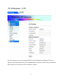
Net Setting page – IP Config
Users can check the ALL network information in this setting. These information’s for
professional users to check the advanced values of network transmission.
Also general users can check some usual values as below introduction.
51
NOTE! : “eth0” means “Wire”, “eth1” mean “Wireless.
About other detail, please send request to Technical Support for more available
information.
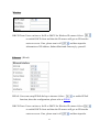
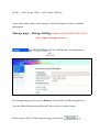
Storage page – Storage Setting (Please note XL-ICA103/ XL-ICA311
don’t support Storage function.)
(Only for OEM models, not supported by
XLICA311)
The storage settings’re for users to Remove external SD or USB storage devices.
Also the Manual Snapshot and Record Video can be set in this setting.
Before remove SD or USB storage devices, please click
52
or
at first.
Manual SnapShot Picture and Record Video functions’ setting:
The Record Time length (for record video) can be set to 1 ~ 5 seconds.
Schedule Snapshot:
Users also can setup the Schedule Snapshot in this setting. The IP camera will save the
snapshot picture every a period of time as user setup to SD or USB storage devices.
NOTE! : If the SD or USB storage device’s full, the IP camera cannot delete or recycle
by itself. Thus please check the storage status anytime or after a period of
time.
53
Chapter 4. Install Client Software
4.1 Foreword
Besides IE browser, we provided a Windows™ based application software in product
CD for using to connect, view and control the IP cameras. Now the software supports
to install on Windows™ XP/VISTA (32bits) operating system.
The software can connect maximum 16 IP cameras (or servers *note ) at the same time
and record the video & audio into hard disk. About the detail of the software function,
please refer to Client Software Functions.
Note:
Client/ Server architecture, each Server can connect 16 cameras (16 channels) and
Client can connect 16 Servers.
Configuration Environment of application software:
• CPU: Pentium Core2 QUAD, 1.8 GHz or above (for 16 IP cameras, triplex)
• Memory Size: 2GB or more recommended
• VGA card resolution: 1024*768 (recommended: Support Overlay function VGA
Card)
• OS: Windows™ XP SP2; VISTA (32 bits) with DirectX9.0c or above
• Other suggestion requirement: CD-ROM.
NOTE! : For example, if you try to connect total 4 IP cameras (servers), you’ll need:
Intel Core 2™ DUAL 1.6GHz CPU, 1GB ram and VGA card with 128MB
ram.
54
4.2 Installation Instruction
Note before install the Client software
Before install the application software of IP camera, please make sure about if you
already used IE browser to view or installed the Mpg4Decoder of IP camera. If not,
please DO install the Mpg4Decoder from the Product CD as below picture before
install this application software. Please click:
After clicking, it will auto install for few seconds and then it will auto finish.
55
Installation of Client software
Step 1. Put the Product CD into the CD-ROM (DVD-ROM) device of your PC. Then
the Auto-Install menu of CD will pop on the screen. Please click
Step 2. Please click
to continue installation or click
another folder.
56
to install to
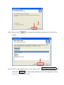
Step 3. Please click
to continue the installation and wait for some time to
install.
Step 4. If below message pop up on screen, please select
then click
and
to continue the installation. If this message doesn’t show
on screen, just ignore this step.
57
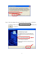
Step 5. After few minutes, the system will show below message to finish the
installation. Please select
and then click
to restart PC.
58
Step 6. After restart, please click
shortcut on desktop or select
→
→
to launch the Client
software.
About how to setup and use the client software, please refer to Client Software
Functions.
59
→
Chapter 5. Client Software Functions
5.1 Foreword
We designed the Client software based on Multi-view of the IP cameras, because users
only can see single IP camera by using IE browser.
The PC based Client software of IP camera’s very easy and convenient to use for setup
a surveillance system. Just need to setup the configurations once and then users can
connect to the IP cameras/servers anytime in the future.
Now we’ll have a general introduction about the first time to setup and use it.
Note! : Before setup the Client software, please check if you know the IP of IP cameras.
If yes, just go ahead to see below instruction of setup the Client software. If not,
please refer to The first time to login and setup IP camera.
5.2 Brief Introduction of Client software interface
Please click
shortcut on desktop or select
→
→
to launch the Client software.
60
→
Quad Vision Modes:
Select to display in 1, 4, 6, 8, 9, 10, 13, 16 quads view.
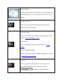
Focused Camera Setting:
Users can click the Camera Number to make it be the
focused camera. Take
(6 Quads) for example, if
you click camera number 9, the biggest preview window
will be changed to Camera 9’s view. Others will be Camera
10, 11, 12, 13 & 14. Please note that you cannot make
random permutation.
61
Status Window:
It will only show the data and time if no connection. After
connected with server, it will show the Server, IP and CH
number.
Connect Server:
Click to get connection with IP cameras which have
already been set in settings.
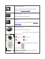
System Setting:
Click to setup the Client software system settings, please
refer to System Settings of Client.
Event Report:
Click to display the log report, please refer to Event
Report.
Remote Schedule Setting:
Click to display the remote schedule settings, please refer
to Remote Schedule Setting.
Record:
Click to record the video/audio from IP cameras via
network transmission. Please note have to press
to enable recording function.
62
Connect Server Setting:
Click to setup about how to connect with IP cameras,
please refer to Connect Server Setting.
Switch Channel:
Click to enable auto-switch channel.
Playback:
Click to start Local Playback. Please refer to Playback of
Client software.
Remote PTZ Control:
Click to control the PTZ in server side.
→ Please select the correct camera number
related to the PTZ.
: Move up
: Move down
: Left
: Right
Click
to adjust the speed of Auto-Patrol of the PTZ
.
as the picture
: For users to control PTZ to
Zoom-In or Zoom-Out.
63
: For users to control PTZ to
Focus-Far or Focus-Near.
: For users to adjust aperture more or less.
Snapshot:
Click to have a snapshot of the video and then you can save
to disk or any storage device on PC.
Remote Talk:
Click to send voice to IP camera’s speaker which been
selected in list via microphone of PC sound card. Please
install a microphone on Client PC and make sure it can
work well. Please note that user will hear the voice from IP
camera automatically if you enable this function.
Remote Speaker:
Click to receive the remote sound of the channel from IP
camera which been selected in list via network
transmission.
64
5.3 Advanced Introduction of Client software
functions
[
] System Settings of Client
Press “System Setting” button will prompt three options for choosing.
System Setting
Remote Setting:
Check the box to enable Direct Draw display if
65
VGA card and driver supported this function.
This setting’s related with
, to set the
time of camera switching from 1 to 10 seconds.
To set the priority of VIDEO or AUDIO for
network transmission.
To set the length of each recording file from 1
minute to 60 minutes.
To set the Recycle recording and the minimum free
space for stabled working system. Please set this to 500MB at least.
To set the recycle days of EVENT reports.
Storage List: To check the box of disk which
can be the storage of recording.
To enable the Sound Alarm of receiving IP
Camera’s motion detect or IO sensor events.
to apply and then just working.
After all settings, please press
66
System Setting
Connect Setting:
Reconnecting Options:
This function is to reconnect with Main (Server) when the network connection’s bad
or disconnected. Check the box of
to enable this function (this will
ignore the “Reconnect Attempts” setting, the program will re-connect continuously).
To set the frequency of reconnection attempting in
and then set the interval time between the
67
attempts in
. Please click
to
apply above settings.
Disconnecting Options
This function is to send alarm out when the network’s disconnected. Check the box of
to enable sound alarm for
to apply above settings.
disconnection. And then please click
System Setting
Event Report:
68
<Event Report>
Firstly please select the time of event log searching.
And then please select the cameras for event log
searching. Click
to select all and click
Finally please press
to un-select all.
to search the event log in system, please wait for
some time. After few time, it will show up the events on list window as below.
<Login Report>
Firstly please select the time of login log
searching.
And then please press
to search the login log in system, please wait
for some time. After few time, it will show up the login logs on list window as below.
69
[
] Connect Server Setting of Client
Server Name: Can be IP Camera or Server.
If Server been selected,
you can select any channel out of 16 channels of servers to display & monitor.
70
Stream: IP camera supports dual-streaming, so you can select to receive
stream 1 or stream 2 of video network transmission.
Connect Type: Select one connection type between the “Only Video”,
“Video&Audio” and “Disable” settings.
Decode Type: If you select stream 1 in above setting, only can have
MP4 (Mpeg-4) for decoding to client. If select stream 2, you can choose MP4 or
M-JPEG for decoding to client software.
Network Protocol: Select the protocol of network (TCP, UDP or
Multicast) according to your network environment.
Motion: Select to Motion Detect Recording in client software settings.
IO: Select to IO Detect Recording in client software settings.
71
NOTE! : If the Motion and IO were not enabled, then the software will record
continuously.
SET (for IO only): Click will prompt a setting window as below:
Please input the Record Time Length (from 7 ~ 60 seconds) of IO detection at IP
camera number. Press
to save the settings.
72
[
] Connect Server Setting of Client
Input the Server Name into
Select the quality
between Auto, Low or High quality.
Then input the IP address of server into
Input the User Name and Password and then you can
change the transmission port of network
keep default as the first time using.
73
. We suggested to
Click
to add into list, click
to delete from list, click
to modify the data which already been in list.
If you don’t know the IP address of IP camera in Intranet, you can use a tool to search
the IP cameras.
Click
will start to search the Security Main servers in LAN as
below. Click
to auto-search the Security Main server under LAN
network. The result will show on list as below.
Just use mouse to select one server and then click
list and then modify the settings.
74
will add into the server
[
] Playback of Client software
The playback of Client can do Local Playback function, please see below instruction to
use it.
Local Playback of Client
NOTE! : All the files and database only can be deleted in Playback program. Please
DO NOT delete or remove the files or database in Windows File Explorer or
other ways. The database may be damaged and cannot be fixed.
NOTE! : This program supports SINGLE and MULTI playback, please press
button to change the playback mode between them.
75
[
] Single Playback
The first time to playback, we suggest to learn how to search the file as you want.
Firstly we have to select the date included the recorded files. You can check the date
list as below, please select the month and day items.
Click
to show the files list which only included VIDEO, click
to show the
files list which included VIDEO + AUDIO (if the hardware supports capturing audio).
Click the camera number
to show the files of the camera recording.
Finally we can select one file to playback in the file list as below.
Click
to start playback process.
Click
to stop, click
Please note that click
is speed-up the playback(up to 8X)and click
speed-low the playback(from 1/2 to 1/8).
76
to pause.
is
Besides, we can check the status of the playback file at below window. This window’s
showing all the detail information of the playback file.
The first line “X1” means the playback speed.
We can move to some point time to check what I want to see by mouse dragging the
slide bar as below.
Click
to increase the sharpness, click
to decrease it.
Click
to increase the brightness, click
to decrease it.
Click
to increase the contrast, click
Click
to REPEAT the playback.
Click
to delete the file.
to decrease it.
Click
to save the AVI file to disk, folder or portable storage devices.
Click
to snapshot one picture of the playback video.
77
Click
to exit and close the playback program, then back to the
surveillance main program to see the live previewing.
Click
to play the last file on list, click
to play the next file on list.
Click
to move forward to previous 1 frame of the playback video, click
to move after 1 frame of the playback video.
Click
image.
to enlarge the image of the playback video, click
to reduce the
NOTE! : Please be advised that above step-forward/back, enlarge/reduce, save to
avi and delete functions better be used under STOP or PAUSE playback
status or the files may be broken by unexpected errors.
[
] Multi Playback
and then change to Multi-Playback mode
Under SINGLE playback mode, click
as below. Under MULTI playback mode, click
program.
78
will back to SINGLE playback
NOTE! : Under MULTI playback mode, please click
to exit the playback
program. Or you can go back to the SINGLE playback program to click
and then back to live previewing. Both ways were okay to exit the playback.
Firstly we have to set a time period of the recorded video to do multi-playback by click
as below. To select the items and then click “OK” to search in database.
79
Only one point we had to note about multi-playback system: The multi-playback
program only can access the searching at THE SAME day in 24 hours. If we want to
check the recorded files between different dates will not be allowed to search.
This limit of multi-playback searching was because of the database will be very busy if
big range searching of the multi-channels at the same time. For stably working system,
we just set the limit in the searching function under multi-playback mode.
Click
to start multi-playback process.
Click
to stop, click
to pause.
Please note that click
is speed-up the playback (up to 8X) and click
speed-low the playback (from 1/2 to 1/8).
80
is
Click
to move forward to previous 1 frame of the multi-playback video, click
to move after 1 frame of the multi-playback video.
The other additional programs of Client software:
About the additional programs of Client software, we provided the hyper-links to check
the functions as below:
The Backup Utility of Client software
The Database Compact of Client software
The Lost File Recovery of Client software
The Utility Tool of Client software
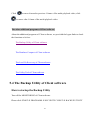
5.4 The Backup Utility of Client software
How to startup the Backup Utility
Turn off the MONITORING of Client software.
Please click START Æ PROGRAMS Æ SECURITY CLIENT Æ BACKUP UTILITY
81
This function was used to backup the video or audio + video files which recorded by
Client software. It cannot be used to backup other files of other software.
We strongly recommended DO NOT use other methods of backup the recorded files or
the whole files will be damaged. Please use BACKUP UTILITY to do backup.
82
How to backup the recorded files
After startup, you can see above backup program window. The program supports two
ways to backup, one is making backup to harddisk and the other is making backup to
CD/DVD burner.
Backup to hard disk:
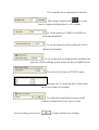
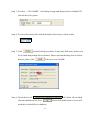
Step 1: To check the box of the camera number and select the cameras for backup.
83
Step 2: To select the date and time for backup period. Please note that file size will be
about 300 MB for total 16 cameras recorded with audio for 1 hour.
Step 3: To select one hard disk space in your system for backup drive. Please DO select
the enough storage for backup.
Step 4: To select the backup files which included video only or video + audio.
Step 5: Click
to start backup procedure. It may take little time, please wait
for it finish and prompt below window.
84
Step 6: Check the box of
will delete all recorded
files and database after click
. Please DO think about it if you still
need the recorded files or database.
Step 7: After click
, please go to the drive or folder as set to backup and then
check the backup’s done or not. Please note that the backup files cannot be
deleted or changed which included the file name and format, or you may not
restore them back later.
Backup to CD/DVD burner:
To take CD burner and Nero™ software for an example to backup in this chapter.
Step 1: To check the box of the camera number and select the cameras for backup.
Step 2: To select the date and time for backup period. Please note that file size will be
about 300 MB for total 16 cameras recorded with audio for 1 hour. For general
CD burning, the space’s about 640 MB.
85
Step 3: To select 『CD: 640MB』 for backup storage and then put the recordable CD
into the drive in system.
Step 4: To select the backup files which included video only or video+audio.
Step 5: Click
to start backup procedure. It may take little time, please wait
for it finish and prompt below window. Please note that Backup Size as below
picture, please click
if the size over 640 MB.
Step 6: Check the box of
will delete all recorded
files and database after click
. Please DO think about it if you still
need the recorded files or database.
86
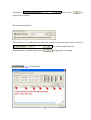
Step 7: After above step, you’ll see below prompt message. Please DO NOT click
. At the meantime, please start-up Nero™ software to burn a CD.
Step 8: After Nero™ software running, please select to burn a 『DATA CD』and then
the Nero™ will prompt to ask for adding files to burn. Then you’ll see the
backup files were already in the list. Just follow general step to click “Next”
and burn the CD. If you don’t see any files in the burning list, just click the
right button of mouse and press 『PASTE』to copy the files into the list. Now
you can press
at above window if the backup files were already in
the Nero™ burning list.
87
NOTE! : In the backup steps, it means the backup size was bigger than the backup
drive or device. Please click
to re-select the items and then
backup again.
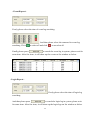
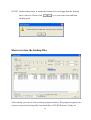
How to restore the backup files
After startup, you can see above backup program window. The program supports two
ways to restore from backup file from hard disk or CD/DVD burner. Firstly we
88
recommended to check the Backup Log for your restoring history as below if you want
to restore from local disk.
Restore steps:
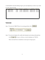
Step 1: To select the TARGET drive for restoring and then click
.
Step 2: To select the database file (.mdb) which already been backup in disk and then
click
. Of course, it allows to select the database in CD/DVD.
Please note that file size should not over the space of target space.
89
Step 3: And then please select the folder or make a new folder to restore the backup
files. To make a new folder, please Click
.
Click
90
to start restoring.
Step 4: If you want to restore the backup files to playback list of Client software, please
restore to “C:\SecurityMDB_Client\”.
Step 5: After restoring finished, t will prompt a message to inform users. Please click
to continue.
NOTE! : In the backup steps, it means the backup size was bigger than the backup
drive or device. Please click
to re-select the items and then backup again.
91
5.5 The Database Compact of Client software
What’s Database Compact?
Database Compact program was designed to fast-scan and re-build the database logs
quickly to more compact and stable.
When need to do Database Compact?
We suggest to run this program every half or one year. Especially to do it when you
find some errors on playback or searching the recorded files. This may help to optimize
the database for playback. Usually to use it with “Lost File Recovery” program
together.
How to startup the Database Compact?
Stop monitor and then turn off the Client software.
Please click START Æ PROGRAMS Æ SECURITY CLIENT Æ DATABASE
COMPACT
92
This function was used to compact the database which was recorded by Client software.
It cannot be used to compact other database files of other software.
After press the Database Compact, please wait for a little time to scan and compact.
And then below message window will prompt to inform users:
Please click
to finish.
If you see below message window prompt on screen:
Please click
again.
93
and then check the database
5.6 The Lost File Recovery of Client software
What’s Lost File Recovery?
Lost File Recovery program was designed to fast-scan and re-build the lost recorded
files.
When need to do Lost File Recovery?
We suggest to run this program especially when you find some errors on playback or
searching the recorded files. This may help to search and re-build the lost recorded files
for playback. Usually to use it with “Database Compact” program together.
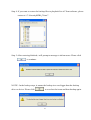
How to startup the Lost File Recovery?
Stop monitor and then turn off the Client software.
Please click START Æ PROGRAMS Æ SECURITY CLIENT Æ LOST FILE
RECOVERY
94
This function was used to recover the files which were recorded by Client software. It
cannot be used to recover other recorded files of other software. After press the
program to launch as below message window will prompt:
95
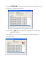
Please click
to start the recover process. After above, please wait for the
recover process working as below window.
NOTE! : Click
will stop the recover process, please note it may cause
some error of recovery.
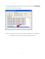
It will show the recover result if the record file has an error which already been
recovered as below.
96
It will prompt the finish message in list as below picture. Please click
exit the “Lost File Recovery” program.
NOTE! : Please DO NOT use other disk-rebuild or defragmenter to do anything on
recorded files or the files may be damaged by unexpected errors.
97
to
5.7 The Set IP Tool software
What’s Set IP Tool?
It’s a program help users to search and find out the IP cameras/servers faster, easier and
much more convenient under Intranet environment. Just needs to press one button to
find them out.
When need to use Set IP Tool?
We suggest to use this program especially while you want to search and setup the IP
cameras or servers in Intranet. So, if the IP camera or server located on Internet, this
program will not search and find them out.
How to startup the Set IP Tool?
Click
on CD Menu
98
or Copy
from Product CD to your PC desktop, click to run.
Choose “Unblock” to enable the Set IP Tool on your PC, click “Exit” from Set IP Tool.
Click on
again to run Set IP Tool.
99
Click on “Config” to modify IP setting.
Click on “WEB” to launch Microsoft™ Internet Explorer for users to login and setup
the IP camera. About the setup detail please refer to To login and setup IP camera.
100
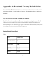
Appendix A: Reset and Factory Default Value
Press and hold the Hardware Reset button on IP camera over 10 seconds to reset the camera
to the factory defaults. You will see the Red indicator LED light again when it is finish reset
procedure.
Tip: The system will reset to the Default IP (192.168.0.100).
Note! : You’ll need to reconfigure the IP camera settings after resetting the camera. The IP
Camera will recover to the factory default username (admin) and password (admin). The
network settings on your camera will also restore to the default value, therefore you may need
to reconfigure the camera using the Utility Tool program.
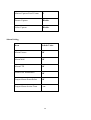
Factory Default Value Sheet
Video
Item
Default Value
Video Resolution
D1
Video Format
NTSC
OSD Timer
Disable
BitRate
1Mbps
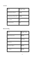
101
Frame Rate
30 fps (stream 1)
Disable of stream 2
Brightness
138
Contrast
71
Saturation
64
Hue
0
Flip
Disable
Zoom
100%
NTP
Item
Default
Value
Synchronized with Time Server
Enable
NTP Server
--
102
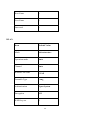
Account
Item
Default Value
Administrator Name
admin
Administrator Password
admin
User Name
user
User Password
user
Motion Setting
Item
Default Value
Motion Detection
Disable
Mask
All clear
Sensitivity
1
Use Direct Draw
Enable
IO Alarm
Disable
103
Motion Capture Post I Frame
1
Picture Capture
Disable
Video Capture
Disable
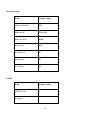
Alarm Setting
Item
Default Value
Alarm Picture
Off
Alarm Mail
Off
Alarm FTP
Off
Video Loss Alarm Mail
Off
Output Alarm Event Select
Off
Output Alarm Action Time
1 sec
104
Audio
Item
Default Value
Audio Channel
Mono
MP2 Bitrate
32kbps
Item
Default Value
User Name
--
Password
--
Password Retype
--
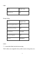
Item
Default Value
Dynamic DNS
Off
DDNS Service
DynDNS.org
PPPoE
DDNS
105
Host Name
--
User Name
--
Password
--
Item
Default Value
Mode
Infrastructure
Operation mode
Auto
Channel
Auto
Wireless AP SSID
PVAP
Preamble Type
Long
Authentication
Open System
Encryption
Off
WEP Key use
1
WLAN
106
WEP Key
--
WPA Encryption
TKIP
WPA PSK
--
Item
Default Value
DHCP Client
Off
PPPoE
Off
IP Address
192.168.0.100
Subnet Mask
255.255.255.0
Gateway
192.168.0.1
DNS 1
168.95.1.1
DNS 2
168.95.192.1
HostName
XL-ICA311
LAN
107
Stream Setting
Item
Default Value
Multicast Enable
Off
Multicast IP
234.5.6.11
Multicast Port
6000
RTSP Port
554
Control Port
21
Alarm Port
22
HTTP Port
80
Item
Default Value
SMTP Server
--
Recipient
--
E-mail
108
Username
--
Password
--
Authentication Mode
PLAIN
Item
Default Value
FTP Server
ServerIP
FTP Port
21
Username
UserName
Password
--
Remote Folder
--
Passive Mode
Off
FTP
109
UPnP
Item
Default Value
UPnP Service
Off
Storage Setting
Item
Default Value
Manual SnapShot Picture
Off
Manual Record Video
Off
Record Time
5 seconds
Schedule Snapshot
Off
Interval
10 minutes
NOTE:
*”--“ means that default value had no meaning.
*MAC address was assigned in factory which cannot be changed by users.
110
Appendix B: Network problematic Utilities
Windows™ operating system includes various network information utilities to
determine various network configurations. To determine your IP address and network
settings, please follow the procedures.
1. Click on “Start” => “Run” and type in: cmd and then press “ENTER”
2. Type command: ipconfig and then press “ENTER”.
3. This will display your network card’s IP address, Subnet Mask, and Default Gateway.
Please remember it, we will use it later.
4. Ping IP Camera’s IP address, the Default IP is 192.168.0.100. Please type in the same
command windows: ping XXX.XXX.XXX.XXX. The XXX.XXX.XXX.XXX is your
IP Camera’s IP address. For example: ping 192.168.0.100.
5. If there is a camera, or a PC or other network device online and using this address, you
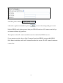
will see:
Pinging 192.168.0.100 with 32 bytes of data:
Reply form 192.168.0.100: bytes=32 time<1ms TTL=128
Reply form 192.168.0.100: bytes=32 time<1ms TTL=128
Ping statistics for 192.168.0.100:
Packets: Sent = 4, Received =4, Lost = 0 (0% loss),
Approximate round trip times in million-seconds:
Minimum = 0ms, Maximum = 0ms, Average = 0ms
111
6. If there is NO response on this address you’ll see
Pinging 192.168.0.100 with 32 bytes of data:
Request timed out.
Request timed out.
Ping statistics for 192.168.0.100:
Packets: Sent = 4, Received =0, Lost = 4 (100% loss),
This indicates that the address is available for use. However, there could still be a device
which is currently offline which is configured to use the address. To be certain, make
sure all your network devices are on and connected to your network when checking for
address availability.
112
Appendix C: Internet Explore Security
Settings
The IP Camera’s web environment Communications using both JavaScript and ActiveX
control technologies. The ActiveX control must be downloaded form the camera and installed
on your PC. There are four things that your Internet Explorer security settings must allow for
the web page to work correctly.
1. Download signed ActiveX controls
2. Run ActiveX control and Plug-ins
3. Script ActiveX controls marked safe for scripting
4. Active Scripting (Java Scripts)
All these things are enabled by the default Internet Explorer Security settings. You can
restore the default settings in Internet Explorer by clicking “Tool” => ”Internet Options” =>
“Security” => “Default Level”.
You can also click “Custom Level” and set each of the four items listed above to “Enable”.
The default security level n Internet Explorer is set to “Medium”.
CAUTION! : You do not need to enable the option foe downloading unsigned ActiveX
controls. Unsigned ActiveX controls may cause problems on your computer or allow hackers
or a virus to be installed on your system without notice. Signed controls have a digital
signature encoded in them verify the identity of the author.
113
Appendix D: Frequently Asked Questions
IP Camera Features
Q: What is an IP Camera?
A: The IP Camera is a standalone system connecting directly to an Ethernet or Fast
Ethernet network and supported by the wireless transmission based on the IEEE
802.11b/g standard. It is different from the conventional PC Camera; the IP Camera
is an all-in-one system with built-in CPU and web-based solutions providing a low
cost solution that can transmit high quality video images for monitoring. The IP
Camera can be managed remotely, accessed and controlled from any PC / Notebook
over the Intranet or Internet via a web browser.
Q: What is the maximum number of users that can be allowed to access IP camera
simultaneously?
A: Maximum number of users that can log onto the IP Camera at the same time is 6.
Please keep in mind the overall performance of the transmission speed will slow
down when multiple users are logged on.
Q: What algorithm is used to compress the digital image?
A: The IP Camera utilizes MPEG4 image compression technology and Motion JPEG
image compression technology to provide high quality images. JPEG is a standard
for image compression and can be applied to various web browser and application
software without the need to install extra software.
114
Q: Can I capture still images from the IP Camera?
A: Yes, you are able to capture still images with the snapshot function from the Client
Software supplied with the IP Camera CD-ROM.
You may also use the first page that shows up when you type in the IP Address of
the server. When viewing this page, click the “refresh” button on your web browser
to update the image. You can right-click the mouse on it and save to a new file.
Also you can type: http://{IP address}:{port}/cgi-bin/image.cgi on IE browser and
then the browser will get a current JPEG file of the live video.
IP Camera Installation
Q: What username and password do I use for the first time access the IP Camera
or after a factory default reset?
A: User Name = admin, password = admin (all lowercase).
Q: What do I do if I can’t remember my username and password?
A: Restore the factory default settings by pressing and holding down the reset button for
60 seconds. Caution: Any configuration settings you have entered will be lost.
Q: Can the IP Camera be used outdoors?
A: IF IP Camera is not weatherproof. It needs to be equipped with a weatherproof case
to be used outdoors and it is not recommended.
115
XL-ICA311 is designed with IP66 weather proof standard, which can be used in
outdoors.
Q: What network cabling is required for the IP Camera?
A: The IP Camera uses RJ-45 Category 5 UTP Twisted-pair cable allowing 10 Base-T
and 100 Base-T networking.
Q: Can the IP Camera be setup as a PC-cam on the computer?
A: No, the IP Camera is used only on Ethernet and Fast Ethernet network or supported
by wireless transmission.
Q: Can the IP Camera be connected on the network if it consists of only private IP
Addresses?
A: Yes, the IP Camera can be connected to a LAN with private IP Addresses.
Q: Can the IP Camera be installed if a firewall exists on the network?
A: If a firewall exists on the network, port 80 is open for ordinary data communication.
You will need to do port forwarding by opening a port to the camera (NAT function).
Please refer to your firewall’s product manual for detailed instructions. Another way
is modify the DMZ function on the Router, re-director the Internet connection Real
IP to the IP Camera’s intranet Virtual IP.
116
Q: I cannot access the IP Camera from a web browser.
A1: The possible cause might be the IP Address for the IP Camera is already being used
by another device. To correct the possible problem, you need to first disconnect the
IP Camera from the network. Then run the PING utility (follow the instructions in
Appendix B: Network problematic Utilities)
A2: Check the Ethernet status LED around the Ethernet ends. It should blink Green and
orange light. If not, check that both ends of the Ethernet cable connection are secure.
A3: Confirm that you are using the correct IP address and port number. You can use the
Utility Tool to observer the status. Please confirm that Camera’s gateway setting
matches the LAN IP of the gateway / router connection it to the Internet. The
gateway may be configured not to respond to pings on its WAN IP.
A4: Confirm that the http port used by the camera (default = 80) is forwarded to the
camera’s LAN IP address in the gateway / router’s configuration. Please refer to
your gateway / router’s manual.
A5: If IP Camera is inside the intranet (Behind a NAT router). Then the Internet
Explorer outside the NAT router can’t access the IP Camera’s IP address. You can
modify Router’s DMZ function or NAT forwarding function let Internet connection
can access the IP Camera. Also you can use DDNS function together to access you
IP Camera in Web address around the world.
Q: How Can I Register DDNS service?
A: Please go to the fallowing DDNS provider or the other DDNS provider company.
Register a account and finish the register procedure. Then apply a Domain on the
DDNS provider. Then input the Domain name (from by DDNS provider), User Name
(account of the DDNS), Password (password for the DDNS) and DDNS Server
117
address (Please find in the DDNS provider Web Page) or the IP Server address in
Your IPCam configuration. Then presses apply for Enable the DDNS services.
For example:
User Name: xxxxxxxx
Password: ●●●●●●●●
Server: dynupdate.dyndns.org
Here are some Free DDNS providers:
http: //www.dyndns.org/ (recommended DDNS provide)
http: //www.3322.org/
DDNS Service must operation under Real IP environment, if the IPCam is behind the
NAT router or the Firewall. Please set NAT redirection or DMZ functions to the
IPCam IP address.
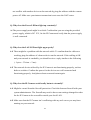
Q: Why E-mail configuration’s correct but cannot send E-mail?
A: Some times user configure E-mail setting is correctly, however the LAN or Wireless
setting configure didn’t setup the DNS server address. Therefore the IPCam cannot
find the correct E-mail server address. So E-mail cannot be sent. So, correction the
DNS server address can solve this problem.
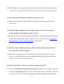
Q: Why camera cannot be pinged?
A: Check the camera is on and the Ethernet status LED is on and blinking. Cycle the
power off and then on and re-check. Confirm that the IP address of the camera does
118
not conflict with another device on the network by ping the address with the camera
power off. Make sure your internet connection is not cross the NAT router.
Q: Why does the Power LED not light up constantly?
A: The power supply used might be at fault. Confirm that you are using the provided
power supply, which is DC 12V, for the IP Camera and verify that the power supply
is well connected.
Q: Why does the LAN LED not light up properly?
A1: There might be a problem with the network cable. To confirm that the cables are
working, ping the address of a known device on the network. If the cabling is OK
and your network is reachable, you should receive a reply similar to the following
(…bytes = 32 time = 2 ms).
A2: The network device utilized by the IP Camera is not functioning properly, such as
hubs or switches. Confirm the power for the devices are well connected and
functioning properly. And please shout-sown and restart again.
Q: Why does the IP Camera work locally but not externally?
A1: Might be caused from the firewall protection. Check the Internet firewall with your
system administrator. The firewall may need to have some settings changed in order
for the IP Camera to be accessible outside your local LAN.
A2: Make sure that the IP Camera isn’t conflicting with any web server you may have
running on your network.
119
A3: The default router setting might be a possible reason. Check that the configuration
of the router settings, allow the IP Camera to be accessed outside your local LAN.
Q: The focus on the IP Camera is bad, how can I correct it?
A: Adjust the IP Camera focus manually, it can turn left and right to adjust for the
correct focus.
Q: Internet Explorer displays the following message: “Your current security
settings prohibit downloading ActiveX controls”.
A: Restore the default IE security settings (Medium) or configure the individual settings
to allow downloading and scripts of signed ActiveX controls. Refer to Appendix C:
Internet Explore Security Settings chapter for more detail.
Q: Internet Explorer displays message: “Error on Page in the status bar in the
lower left corner of the web page”.
A: Most likely, the camera ActiveX control did not download and install correctly.
Check your Internet Explorer security settings and them close and restart Internet
Explorer. Try to browser and log in again.
Q: How can I tell if the camera’s ActiveX is installed on my PC?
A: Go to C: \Windows\Downloaded Program files and check to see if there is an entry
for the file Cam Image Class. The status column should show “Installed”. If the file
is not listed, make sure your Security Settings in Internet Explorer are configured
120
properly and then try reloading the camera’s home page.
Q: My browser does not seem to work too well with the IP Camera?
A: Make sure that you are using Internet Explorer 5.0 or higher. If you are experiencing
problems, try upgrading to the latest version of Microsoft’s Internet Explorer from
the Microsoft website ate: http: //www.microsoft.com/windows/ie
Q: Noisy images occur. How can I solve the problem?
A: The video images might be noisy if the IP Camera is used in a very low light
environment. To solve this issue you need more lighting.
Q: There are no images available through the web browser?
A1: The ActiveX might be disabled. If you are viewing the images from Internet
Explorer 7.0 above and make sure ActiveX has been enabled in the Internet Options
menu. Please see Appendix C: Internet Explore Security Settings to configure your
Internet Explorer.
A2: Make sure that your web browser supports ActiveX. If you are using Internet
Explorer with a version number of lower than 4, then you will need to upgrade your
web browser software in order to view the streaming video transmitted by the IP
Camera.
121
Q: When I use IPCam Wi-Fi mode, seems it always can’t connect. But the Wi-Fi
setting is correct. What should I Do?
A: Sometimes according to your environment, some channel of Wi-Fi is jam or to much
noise. So batter changes a channel for batter signal for IPCam. Please configuration
your Wi-Fi AP or Wi-Fi AP Router Wi-Fi Channel to another channel. Then restart
the IPCam to connect the new channel of Wi-Fi signal.
Q: What can I do if I have more questions?
A: We hope your experience with IP Camera is enjoyable; you may experience some
issues or have some questions that this Q&A has not answered. To obtain the newest
information and support for your IP Camera, please call or mail to our Sales dept.
([email protected]) for additional help.
122
Appendix E: PoE (optional) Technical
specifications
Important of POE (Power over Ethernet) pins definition:
Pin
Alternative B
1
--
2
--
3
--
4
Vport Positive
5
Vport Positive
6
--
7
Vport Negative
8
Vport Negative
Appendix F: 3G Mobile Surveillance
compatible list
Dopod CHT 9000, 9100, 9110
Dopod 595
All HTC series
Nokia N93, N95
Nokia N80
Motorola E1070
Motorola raza 3.x
Motorola V3x
Sony Ericsson K608i
Sony Ericsson K610i
Sony Ericsson W900i
How to connect IP camera with 3G mobile phones.
Step 1. Use mobile phone to link 3G network and then launch the Internet browser of
3G mobile. (Note! : For 3G mobile surveillance, the IP cannot be virtual IP)
Step 2. In the network address, please input the IP address of your IP camera follow
below examples (assume the IP camera’s IP is 192.168.0.100).
For STREAM 1 3GPP, please input: rtsp://192.168.0.100/3g
For STREAM 2 3GPP, please input: rtsp://192.168.0.100/3gv2
About the streaming settings, please refer to System Set - Video
124
Appendix G: Note of Network Ports and
SD/USB compatible list
1. the ports used on IP camera
a. Unicast (TCP), port=554, 21
b. Unicast (UDP), port=554, 21
c. Multicast (UDP), port=554, 21, 6000, 6002
Please be noted that, On IE, Multicast mode only can be enabled, and the Multicast
mode is really running on Client software only, it can not be run on IE.
Http port=80
Alarm port=22
Audio port (from PC to IP camera) = 1500
2. Some limitation on SD and USB
a. the maximum capacity of SD is 4GB
b. the maximum capacity of USB interfaced storage is 80GB
c. only support NTFS file system on USB interfaced storage
d. the power of USB interfaced storage should be self-powered, rather than the IP
Camera.
e. the suggested models of USB interfaced storage are PNY, ASUS, Sandisk, NuSlim,
eSENSE
3. How to identify the IP Camera is wired or wireless by our firmware?
If you want use wired mode, please have the Ethernet cable connected, if you have the
Ethernet cable disconnected, the firmware will detect it and set the IP camera to be
wireless mode.
125