1
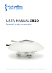
0344 200
INSTRUCTION MANUAL
IMPORTANT USER INFORMATION
Reading this entire manual is recommended for full understanding of the use of this product.
The exclamation mark within an equilateral triangle is intended to alert the user to the presence of important
operating and maintenance instructions in the literature accompanying the instrument.
Should you have any comments on this manual we will be pleased to receive them at:
Kipp & Zonen B.V.
Delftechpark 36
P.O. Box 507,
2628 XH Delft, Netherlands
2600 AM Delft, Netherlands
Telefon
Fax
E-mail
+31 (0)15 2755-210
+31 (0)15 2620-351
[email protected]
Kipp & Zonen reserve the right to make changes to the specifications without prior notice.
WARRANTY AND LIABILITY
Kipp & Zonen guarantees that the product delivered has been thoroughly tested to ensure that it meets its
published specifications. The warranty included in the conditions of delivery is valid only if the product has
been installed and used according to the instructions supplied by Kipp & Zonen.
Kipp & Zonen shall in no event be liable for incidental or consequential damages, including without limitation,
lost profits, loss of income, loss of business opportunities, loss of use and other related exposures, however
caused, arising from the faulty and incorrect use of the product.
User made modifications can affect the validity of the CE declaration.
COPYRIGHT© 2004 KIPP & ZONEN
All rights reserved. No part of this publication may be reproduced, stored in a retrieval system or transmitted
in any form or by any means, without permission in written form from the company.
Manual Version 0905-D
Instruction Manual NR LITE
1
2
Instruction Manual NR LITE
TABLE OF CONTENTS
IMPORTANT USER INFORMATION
1
1.
GENERAL INFORMATION
5
1.1
Five minutes user guide
6
2.
SENSOR PROPERTIES
9
2.1
Electrical
9
2.2
Spectral
10
2.3
Directional- / Cosine response
10
2.4
Sensitivity to wind speed
11
2.5
List of specifications
11
2.6
Dimensions
12
3.
CALIBRATION
13
4.
INSTALLATION AND MAINTENANCE
15
5.
TROUBLE SHOOTING
17
6.
DELIVERY
17
7.
ACCESSORIES
17
Instruction Manual NR LITE
3
4
Instruction Manual NR LITE
GENERAL INFORMATION
1.
GENERAL INFORMATION
The net radiometer NR LITE is an instrument for measuring solar and far infra red radiation balance. This
balance is usually called net (total) radiation. Its up facing sensor measures the solar energy and far infra
red energy that is received from the entire hemisphere (180 degrees field of view). Its down facing sensor
measures the energy received from the soil surface. The down facing sensor reading is automatically
subtracted from the up facing sensor value and converted to one output signal. The resulting output
represents the net radiation, which can be interpreted as the radiative energy that is absorbed by the soil
surface. The output is expressed in Watts per square metre.
The net radiometer is designed for continuous outdoor use. Contrary to most common instruments for
measurement of net radiation, it is not equipped with plastic domes. The domes are replaced by a Teflon
coated sensor surface. This has big advantages for maintenance and sensor stability, it also has
disadvantages; most particularly a higher sensitivity to wind speed (see 2.4). Therefore the accuracy of
the instrument is limited.
In its most frequent application the net radiometer is used for measuring the radiation balance as a
meteorological parameter. It can however also be used to measure indoor climate radiative stress.
The net radiometer is equipped with a bubble level for easy leveling the instrument.
The NR LITE fully complies with
directive 89/336/EEC.
Instruction Manual NR LITE
5
GENERAL INFORMATION
1.1
Five minutes user guide
Requirements:
1. net radiometer
2. voltmeter with a range from 0 to 50 millivolt and an input impedance of more than 5000 Ω
3. light
4. a table
Position the instrument such that the down facing sensor is 1 centimeter over a surface (e.g. a table), and
the upper sensor is facing the lamp. Please avoid contact between the sensor and your hand; this
creates thermal shocks to which the sensor is sensitive. Hold the sensor at the rod at all times.
• Connect the net radiometer wires to the voltmeter, the white wire to the voltmeter +, the green wire to
the voltmeter -.
• Put the voltmeter range to the most sensitive.
• With the lamp off, read the sensor signal (it takes about a minute for the signal to stabilize).
• Expose the sensor to light. The signal should give a more positive reading.
• Put the lamp off again, the signal should slowly return to the old signal level. This shows that the
sensor is sensitive to light.
• Put the sensor upside down. The signal should reverse sign (+10 mV should become -10 mV),
because it measures upper minus lower sensor. Don’t worry about a 20% difference under these
conditions! If OK, put the sensor in its original position again, and let it stabilize.
• Put your hand over the upper sensor. The signal should give a more positive reading, provided that
the sensor temperature is lower than the temperature of your hand. If the temperature of your hand is
lower than the temperature of the sensor, the signal will go more negative.
• The sensitivity to thermal shocks can be demonstrated by touching the sensor edge (the blank metal)
with your hand for some seconds. The resulting shock will result in a signal drift, or a zero offset that
only slowly will settle down again.
• Adjust the voltmeter range in such a way that the expected full scale output of the net radiometer fits
the full scale input of the voltmeter. This can be done on theoretical considerations. (When the
maximum expected radiation is +1500 W/m² metre, the minimum is -200 W/m², and the sensitivity of
the net radiometer is 10 µV per W/m², the expected output range of the pyranometer is 1700 W/m² x
10 µV/W/m² = 17000 µV = 17 mV = 0.017 V). These values are applicable for normal meteorological
applications.
• Calculate the radiation intensity by dividing the net radiometer output (0.017 volts) by the calibration
factor (0.000010 volt per watt per square metre).
6
Instruction Manual NR LITE
GENERAL INFORMATION
• For permanent installation mounting should be done using the net radiometer mounting rod. The
sensor should be mounted in a field which is free from obstructions. Under no condition a shadow
should be cast upon it.
• Maintenance: the sensor should be kept clean, using water or alcohol. Please treat the surface gently.
• Recalibration is suggested every two years, preferably by letting a higher standard run parallel to it
during two sunny days, and by comparing the daily totals. This reference could be a net radiometer
type CNR1, or a NR LITE that is kept safely in the cupboard (sensor stability mainly is a matter of
aging of the sensor surface black paint). Another way of checking sensor performance during field use
is to put the sensor upside down during stable atmospheric conditions. Theoretically the sensor output
should change sign. This method is no more accurate than 20% because of the fact that the sensor
symmetry is no more accurate than this.
Instruction Manual NR LITE
7
8
Instruction Manual NR LITE
SENSOR PROPERTIES
2.
SENSOR PROPERTIES
The net radiometer consists of a thermopile detector, two black Teflon coated sensor surfaces, a housing
and a cable.
The thermopile consists of a number of thermocouples that are connected in series. It essentially is a
very sensitive differential temperature sensor. The thermopile generates a voltage output (the sensor is
passive, no power supply required).
The up facing sensor surface is connected to the upper joints of the thermopile, the down facing sensor is
connected to the lower joints of the thermopile. The sensor will measure the temperature difference
between the upper and the lower sensor surface. This temperature difference can very accurately be
determined (changes of less than 0.001 degree are detectable. The temperature difference is
proportional to the net radiation.
Most electrical specifications are determined by thermopile. Spectral specifications are determined by the
black Teflon coating.
Both the up facing and the down facing sensors have a field of view of 180 degrees, and their angular
characteristics fulfill the so-called cosine response.
2.1
Electrical
The electrical circuit of the net radiometer is drawn in figure 1. The nominal output resistance of the net
radiometer is 2.3 Ω. This implies that the input impedance of the readout equipment should at least be
2300 Ω in order to make an error of less than 0.1 percent.
Cable can be extended without problems to a length of 100 metres, provided that cable resistance is less
than 0.1 percent of the input impedance of the readout equipment.
The electrical sensitivity of the thermopile changes with the temperature. A nominal value for this is not
specified. Calibration is done at 20 degrees Celsius.
radiation
thermopile
white
green
shield
Figure 1
Electrical circuit of the net radiometer
Instruction Manual NR LITE
9
SENSOR PROPERTIES
2.2
Spectral
The spectral properties of the net radiometer are determined by the Teflon sensor surface. The spectral
sensitivity is not specified in our list of specifications because it is not considered to be of critical
importance. A sketch of approximate spectral sensitivity is given in figure 2.
Figure 2
The approximate spectral sensitivity of the net radiometer combined with the spectrum of
the sun under a clear sky, and the spectrum of outgoing far infra red radiation.
The up facing sensor has been calibrated for solar radiation wavelengths. It is assumed that the lower
sensor has the same sensitivity. This might not be true; the sensor can have a non perfect symmetry.
This however is neglected. Secondly it is assumed that the sensor sensitivity to infra red radiation is the
same as for solar radiation.
2.3
Directional- / Cosine response
The measurement of the radiation falling on a surface (also called irradiance or radiative flux) requires
two assumptions: that the surface is spectrally black (that it absorbs all radiation from all wavelengths,
see previous paragraph) and that it has a field of view of 180 degrees. Another way of expressing these
directional properties is to say that the sensor has to comply with the cosine response.
The net radiometer sensor surface has a rather special shape, it is shaped like a cone, in order to have a
better compliance with the cosine response.
A perfect cosine response will show maximum sensitivity (1) at an angle of incidence of 90 degrees
(perpendicular to the sensor surface) and zero sensitivity at an angle of incidence of 0 degrees (radiation
passing over the sensor surface). In between 90 and 0 degrees the sensitivity should be proportional to
the cosine of the angle of incidence. Figure 3 shows the behavior of a typical net radiometer. The vertical
axis shows the deviation from ideal behavior, expressed in percentage deviation of the ideal value.
10
Instruction Manual NR LITE
SENSOR PROPERTIES
Figure 3
The directional response or cosine response of the net radiometer.
On the horizontal axis the zenith angle (0 degrees zenith angle equals 90 degrees angle
of incidence). On the vertical axis the percentage deviation from ideal cosine behavior.
The specifications of the net radiometer regarding the cosine response are very good
because the dedector surface is shaped like a cone.
2.4
Sensitivity to wind speed
The net radiometer is calibrated at zero wind speed. At higher wind speeds, the sensitivity and thus
voltage output will decrease. Using the original sensitivity figure will result in too low net irradiances. The
design however was made such that this error generally will not be large, so that correction is not
necessary. This is achieved by keeping the sensor-∆T low.
For scientific research to this matter a correction theoretically could be done by multiplying the calculated
irradiances with a factor (1+x.v3/4) where v is the wind speed in m/s, and x has to be determined
empirically. x is found to be approx. 0.01.
2.5
List of specifications
Electrical
•
•
•
•
•
•
•
Impedance (nominal):
Response time (1/e):
Sensitivity (nominal):
Expected signal range under atmospheric conditions:
Stability:
Non linearity (estimated):
Temperature dependence of sensitivity:
Instruction Manual NR LITE
2,3 Ω
< 20 s
10 µV/W/m2
-25 to +25 mV
< ± 2% per year
< 1 % up to 2000 W/m2
not specified
11
SENSOR PROPERTIES
Spectral
•
•
•
•
0,2 - 100 µm
Thermopile
Teflon coating
Cone
Spectral range:
Detector type:
Detector protection:
Detector shape:
Directional
•
•
Directional error 0 - 60
degrees at 1000 W/m2
Sensor asymmetry:
< 30 W/m2
± 20%
Mechanical
•
•
•
•
•
Material of housing:
Material of cable:
Weight:
Cable length:
Dimensions:
Anodised aluminium
Poly Urethane
200 g
15 metres
see figure 4
Environmental
•
-30 °C to +70 °C
Working temperature range:
Calibration conditions:
•
•
•
2.6
the upper sensor is calibrated for solar radiation
traceable to Kipp & Zonen secondary standard pyranometer
normal incidence, 500 Watt per metre square, 20 degrees Celsius, horizontal position, zero wind
speed
Dimensions
cable length 15 m
support arm d = 20 mm x L = 800
Figure 4
12
The dimensions of the net radiometer in mm, white lead positive / green lead
negative
Instruction Manual NR LITE
CALIBRATION
3.
CALIBRATION
The up facing sensor of the net radiometer is the one that is calibrated for solar radiation. It is assumed
that the sensitivity of the downfacing sensor is the same. In reality this might differ. (see specifications).
This error is accepted because the down facing sensor signal will generally be at least a factor 3 smaller
than the signal of the up facing sensor. Also it is assumed the sensitivity to infra red radiation is the same
as for solar radiation. The error caused by this is unknown. It is neglected because the solar radiation will
be the dominating factor. Another error is caused by wind this error is specifically treated in chapter 2.4.
During calibration there is no wind. It is suggested not to correct for this; to improve the accuracy of this
instrument would require more than a wind correction. The up-facing sensor of the NR LITE net
radiometer reference is calibrated against a Kipp & Zonen secondary standard pyranometer (this is a
radiometer that is sensitive to solar radiation only) under natural sunlight during clear sky conditions.
Further reference conditions are as follows: temperature 20 degrees Celsius, irradiance 500 Watts per
square metre, wind speed < 2 m/s. The primary standard for solar radiation, against which the secondary
standard pyranometer is calibrated, is the World Radiometric Reference.
Instruction Manual NR LITE
13
14
Instruction Manual NR LITE
INSTALLATION AND MAINTENANCE
4.
INSTALLATION AND MAINTENANCE
When installed permanently, the net radiometer can be attached to a mast using the rod that is attached
to the sensor. The rod diameter is standardized to Kipp & Zonen diameter. Leveling will be based with the
built in bubble level.
When installed on a mast, preferred orientation is such that no shadow is cast on the net radiometer
during any time of the day. On the northern hemisphere this implies that the net radiometer should be
south of the mast.
It is advised to measure at a height h of at least 1.5 meters above the surface in order to avoid shading
effects and to promote spatial averaging.
The down facing sensor signal is representative (99%) for a circular area with radius 10 h.
The net radiometer is an all weather instrument.
Once installed it needs little maintenance. It is suggested to clean the detector as part of a regular
routine, using water or alcohol.
Recalibration is suggested every two years, preferably by letting a higher standard run parallel to it during
two sunny days, and by comparing the daily totals. Preferably daily totals of several days should be
compared. Calibration factor could be corrected if results differ by more than five percent. The reference
could be a net radiometer type CNR1, or a NR LITE that is kept safely in the cupboard. Another way of
checking sensor performance during field use, is to put the sensor upside down during stable
atmospheric conditions. Theoretically the sensor output should change sign. Please mind that the sensor
response time for stabilizing is about one minute. This method is no more accurate than 20% because of
the fact that the sensor symmetry is no more accurate than this.
A third way is to let a recalibration be performed at Kipp & Zonen in Delft.
Instruction Manual NR LITE
15
16
Instruction Manual NR LITE
TROUBLE SHOOTING / DELIVERY / ACCESSORIES
5.
TROUBLE SHOOTING
If your net radiometer does not seem to work at all, please follow the following procedure:
• Check if the net radiometer reacts to light, using the procedure in the "five minutes user manual”.
• No result? Measure the impedance of the sensor across the white and the brown wires. This should
be close to 2.3 ohms. If it is close to five ohms, there is a short circuit. If it is infinite, the thermopile is
blown.
If the net radiometer shows bigger or smaller results than expected, the following questions might help
you out:
• Are you measuring under natural sunlight? If so the maximum expected radiation is 1500 Watts per
square metre. Under lamps this might be more. For indoor climate studies, smaller values are
expected unless solar radiation is present. A typical value for a room when facing a wall and a
relatively cold window is 50 Watts per square metre.
• Are you correcting for the calibration factor? Please note that this factor is an individual property,
which is different for each sensor. Do you divide by the factor? This is correct.
• What is the input impedance of your readout equipment? It should preferably be more than 5000 ohm.
If smaller than 250 ohm you will notice errors.
• Is your readout equipment properly calibrated?
If still no satisfactory answer is found, please contact your supplier.
6.
DELIVERY
Delivery includes:
1 net radiometer
1 bird stick (to be installed on the net radiometer)
1 calibration certificate
7.
ACCESSORIES
No options or accessories are available.
Instruction Manual NR LITE
17
18
Instruction Manual NR LITE
RECALIBRATION FORM
NAME:
_________________________________________________________________________
COMPANY / INSTITUT: _________________________________________________________________________
ADDRESS:
_________________________________________________________________________
POSTCODE / CITY:
_________________________________________________________________________
COUNTRY:
_________________________________________________________________________
PHONE:
_________________________________________________________________________
FAX:
_________________________________________________________________________
I would like to receive a price list for recalibration
I would like to submit my instruments for recalibration
Type / Model:
Qty
Requested delivery time
I intend to send the instrument(s) to
Gengenbach Messtechnik on:
. . . . . ./. . . . . ./. . . . . .
I would like to receive the instrument(s) back on:
. . . . . ./. . . . . ./. . . . . .
Conformation by Gengenbach Messtechnik
Yes, the dates are acceptable to us
No, unfortunately the dates do not fit into our calibration schedule.
We suggest the following dates:
. . . . . ./. . . . . ./. . . . . .
. . . . . ./. . . . . ./. . . . . .
Fax +49 – (0)7153 – 9258 - 160
or by mail to:
Gengenbach Messtechnik, Heinrich-Otto-Straße 3
D – 73262 Reichenbach / Fils
Instruction Manual NR LITE
19
RECALIBRATION FORM
NAME:
_________________________________________________________________________
COMPANY / INSTITUT: _________________________________________________________________________
ADDRESS:
_________________________________________________________________________
POSTCODE / CITY:
_________________________________________________________________________
COUNTRY:
_________________________________________________________________________
PHONE:
_________________________________________________________________________
FAX:
_________________________________________________________________________
I would like to receive a price list for recalibration
I would like to submit my instruments for recalibration
Type / Model:
Qty
Requested delivery time
I intend to send the instrument(s) to
Gengenbach Messtechnik on:
. . . . . ./. . . . . ./. . . . . .
I would like to receive the instrument(s) back on:
. . . . . ./. . . . . ./. . . . . .
Conformation by Gengenbach Messtechnik
Yes, the dates are acceptable to us
No, unfortunately the dates do not fit into our calibration schedule.
We suggest the following dates:
. . . . . ./. . . . . ./. . . . . .
. . . . . ./. . . . . ./. . . . . .
Fax +49 – (0)7153 – 9258 - 160
or by mail to:
Gengenbach Messtechnik, Heinrich-Otto-Straße 3
D – 73262 Reichenbach / Fils
20
Instruction Manual NR LITE
RECALIBRATION FORM
NAME:
_________________________________________________________________________
COMPANY / INSTITUT: _________________________________________________________________________
ADDRESS:
_________________________________________________________________________
POSTCODE / CITY:
_________________________________________________________________________
COUNTRY:
_________________________________________________________________________
PHONE:
_________________________________________________________________________
FAX:
_________________________________________________________________________
I would like to receive a price list for recalibration
I would like to submit my instruments for recalibration
Type / Model:
Qty
Requested delivery time
I intend to send the instrument(s) to
Gengenbach Messtechnik on:
. . . . . ./. . . . . ./. . . . . .
I would like to receive the instrument(s) back on:
. . . . . ./. . . . . ./. . . . . .
Conformation by Gengenbach Messtechnik
Yes, the dates are acceptable to us
No, unfortunately the dates do not fit into our calibration schedule.
We suggest the following dates:
. . . . . ./. . . . . ./. . . . . .
. . . . . ./. . . . . ./. . . . . .
Fax +49 – (0)7153 – 9258 - 160
or by mail to:
Gengenbach Messtechnik, Heinrich-Otto-Straße 3
D – 73262 Reichenbach / Fils
Instruction Manual NR LITE
21
22
Instruction Manual NR LITE
NOTICE
Instruction Manual NR LITE
23
24
Instruction Manual NR LITE
Customer Support
Our customer support
remains at your disposal
for any maintenance or
repair, calibration,
supplies and spares.
The address is as follows:
Für Servicearbeiten und
Kalibrierung, Verbrauchsmaterial und Ersatzteile
steht Ihnen unsere
Customer Support
Abteilung unter folgender
Adresse zur Verfügung:
Notre service 'Support Clientèle'
reste à votre entière disposition
pour tout problème de
maintenance, réparation ou
d'étalonnage ainsi que pour les
accessoires et pièces de rechange.
Leur adresse est la suivante :
Holland
Kipp & Zonen B.V.
Röntgenweg 1
2624 BD DELFT
T +31 15 269 8000
F +31 15 262 0351
E [email protected]
USA
UK
Kipp & Zonen Ltd.
P.O. Box 819,
LINCOLN, Lincolnshire LN6 0WY
T +44 1522 695 403
F +44 1522 696 598
E [email protected]
France Kipp & Zonen S.A.R.L.
7, avenue Clément Ader
ZA Ponroy - Bât. M
F-94420 LE PLESSIS TREVISE
T +33 1 49 62 4104
F +33 1 49 62 4102
E [email protected]
Germany Gengenbach Messtechnik
Heinrich-Otto-Strasse 3
D-73262 REICHENBACH/FILS
T +49 7153 9258 0
F +49 7153 9258 160
E [email protected]
WWW.RG-MESSTECHNIK.DE
Kipp & Zonen USA Inc.
125, Wilbur Place
BOHEMIA/NY 11716
T +1 631 589 2065
F +1 631 589 2068
E [email protected]
Kipp &
Zonen
www.kippzonen.com