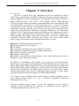
1
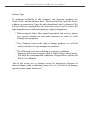
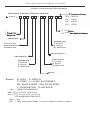
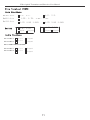
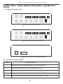
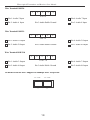
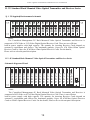
Fiber Optical Transmitter and Receiver User Manual Video, Audio, Data, Ethernet Digital Optical Transmitter and Receiver USER MANUAL Fiber Optical Transmitter and Receiver User Manual Solemn Tips: To maintain credibility of the company, our company products are sticked with anti-demolition label, The user shall not open the device without our permission. Once the anti-demolition Label is damaged ,We will not bear any responsibility for after-sales service and to reserve the right complaints for intellectual property rights infringement . * When using the Video fiber optical transmitter and receiver, please pay special attention to anti-static measures in order to avoid damage the equipment * The Company reserves the right to change products, we will not notify customer if some changes for products. * The following cases do not belong to warranty conditions: Improper access power supply such as High voltage, anti-polarity; Not meet the environmental conditions of application; operate not follow User Manual; Due to the wrong use or damage caused by negligence; Because of other accidents (such as lightning, water, fire, etc.) as well as all damage caused by man-made factors etc! Fiber Optical Transmitter and Receiver User Manual Products classification and order information Video optical Transmitter & Receiver name rule: Ex: XXXX D V A D Transmission Distance K MM:2KM SM: SM : 20KM SM : 40KM SM : 60KM E 10 T Transmitter R Receiver 100 10M Ethernet 10/100M Auto Adaptive Ethernet 请教郑工Video Channel 视频通道数 Switch Direction F Forward R Reverse Bi Bidirection Video direction NoForward direction and Bidirection Switch channel No. Audio channel No. Audio Direction F Forward R Reverse Bi Bidirection Data Direction F Forward R Reverse Bi Bidirection Data No Remark : D= DATA; S= SWITCH V=VIDEO;A= AUDIO; E=ETHERNET SM= SINGLE MODE;MM= MULTI MODE T= TRANSMITTER;R= RECEIVER Note: ①.FIBER TRANSMISSION MM:50/125 62.5/125 100/140μm SM:8.3/125 8.7/125 9/125 10/125μm ②TRANSMISSION DISTANCE MM:>: 2km SM:> 20km 40km 60km 100km,Can excess 120km as customers’ request Fiber Optical Transmitter and Receiver User Manual Content 1. Overview 2. Technical standards and instructions 2.1. Fiber technical parameters 2.2 Video Interface (VIDEO) 2.3 Audio Interface (AUDIO) 2.4 Data and Switch Interface (DATA, SWITCH) 3. Mini 1Ch Video+1Reverse Data Optical Transmitter and Receiver Series 3.1 Schematic diagram of Panel 3.2 Description of indicator lights 3.1 Description of connection for wire in panel. 4. 1Ch Video /Data Optical Transmitter and Receiver Series 4.1 Schematic diagram of Panel 4.2 Description of indicator lights 4.3 Description of connection for wire in panel. 5. 2Ch Video/Data Optical Transmitter and Receiver Series 5.1 Schematic diagram of Panel 5.2 Description of indicator lights 5.3 Description of connection for wire in panel 6. 4Ch Video/Audio/Data Optical Transmitter and Receiver Series 6.1 Schematic diagram of Panel 6.2 Description of indicator lights 6.3 Description of connection for wire in panel. 7. Multifuntional 2Ch Video Optical Transmitter and Receiver Series 7.1 Schematic diagram of Panel 7.2 Description of indicator lights 7.3 Description of connection for wire in panel. Fiber Optical Transmitter and Receiver User Manual Content 8. 8Ch Video/Audio/Data Optical Transmitter and Receiver Series 8.1 Schematic diagram of Panel 8.2 Description of indicator lights 8.3 Description of connection for wire in panel. 9. 16Ch Video/Audio/Data Optical Transmitter and Receiver Series 9.1 Schematic diagram of Panel 9.2 Description of indicator lights 9.3 Description of connection for wire in panel. 10. Multifuntional 16Ch Video Optical Transmitter and Receiver Series 10.1 Schematic diagram of Panel 10.2 Description of indicator lights 10.3 Description of connection for wire in panel. 11. 2U/4U Standard Rack Mounted Video Optical Transmitter and Receiver Series 11.1 2U Standard Rack mounted schematic diagram of Panel 11.2 4U Standard Rack mounted schematic diagram of Panel 12. Device Installation 12.1 Inspection for opening Box 12.1 Application Diagram Fiber Optical Transmitter and Receiver User Manual Chapter 1: Overview 1.1 Overview All series of digital fiber optic transmitter and receiver adopted the special ASIC design and the high-speed DSP technology full digital without compression, without damaged broadcast transmission, can transmitte long distance analog or digital DVR Recorder, VCR, DVD / VCD, Digital Camera, High-definition Television, High-resolution baseband 8 MHz bandwidth video signal through fiber with high-quality, no damaged to remote monitoring center. It is the use of digital technology that avoid incuring cross-modulation distortion interference, image and control data crosstalk each other, poor stability, the impact of environmental factor caused by analog FM, phase modulation, amplitude modulation. The independent modules or rack, Gigabit optical transmission technology have high-capacity, easy to upgrade, single, multimode fiber transmission, distance 0-100 KM; Support any high-resolution video signals, video relay nondestructive renewable, automatically compatible with PAL, NTSC, SECAM video formats, APC circuit, stable optical power output, large dynamic range. Its Main applications as below: ◆Intelligent Traffic Monitoring System (ITS) ◆The large-capacity Security System ◆ TV medical ◆ Long-distance broadcast television transmission system ◆ Long-distance multimedia teaching / campus monitoning ◆ Television /telephone conference ◆ Building control system ◆Occasions requirements for high-definition video, audio transmission .such as: Big public square, Big stadium, Airport. In addition to transmitting video signals, also provide you with multi-channel Bdirectional audio signal and multi-channel RS232/RS485/422 data signals for option. Multi-channel Bidirectional audio signals adopted full-digital uncompressed 24 bits high dynamic audio technology, it can support any hi-fi, stereo audio without distortion for transmission, the digital format complies with DVD format. Multichannel Bidirectional data used for controlling camera pan-tilt or video matrix switching and professional data interface for RS232/RS485/RS422. It is complete use of industrial Chips and all surface sticking technology, hence posses high reliability. Support -45 ~ +85 °C industrial environment of high and low temperatures; Using advanced switching power supply to ensure that equipment last for long-term operation without breakdown The card-type or standalong structure apply to centralized management 2U and 4U rack. 1 Fiber Optical Transmitter and Receiver User Manual 1.2 Functions and Features 1.2.1 Using high quality optoelectronic components provides good optical properties and electrical properties to ensure reliable data transmission, long working life. 1.2.2 plug-and-play design gets simple installation, no need for adjustment at the scene. The design complying with industrialization and modular standards enable equipments to be reliable flexible, Gigabit fiber transmission, large capacity, easy to upgrade. 1.2.3 provide a plentiful power status indicator, fiber link state, the video signal input and output, audio input and output, data input and output functions of effective indication, which enables users to easily conveniently install and test equipment. 1.2.4 support any high-resolution video signals, automatically compitable with PAL, NTSC, SECAM and other video formats; video interface in a standard 75 Ω BNC, power supply and other parameters status of the LED indicator can show the operation of the surveillance system. 1.2.5 It is the use of digital technology that avoid incuring cross-modulation distortion interference, image and control data crosstalk each other, poor stability, the impact of environmental factor caused by analog FM, phase modulation, amplitude modulation. 1.2.6 The connection and installation for all Single fiber video optic transmitter and reciver equipment is same as dual-fiber, but single fiber video optic transitter and receiver equipment be used only in pairs (1310 nm matchs with 1550 nm ) 1.2.7 support single-mode optical interface, transmission distance from 0 to 25 Km, the most long-distance can reach over 100 km , the optical interfaces : FC, SC or ST interface. 1.2.8 fully meets operating requirements for professional-level mornitoring, the average fault-free working hours is over 100,000 hours. 1.2.9 Perfect after-sale service, we can provide one month change new product. if is not artificial, one -year warranty of quality commitment. 2 Fiber Optical Transmitter and Receiver User Manual ChapterII: Technical standards and instructions Technical Parameters 2.1 Fiber optic Technical Parameters Technology Parameters Wavelength (nm) Fiber type Optical features Parameters 850/1310 1310/1300 Multi Mode 1550 Single Mode type of fiber interface FC, SC, ST FC, SC, ST FC/SC Transmission distance (km) 0~2 0~20 0~40 0~60 0~80 15~120 Transmission power (dBm) -14~18.5 -7~-16 -9~-4 -4~0 +1~-8 -5~0 Receiving Sensitivity (dBm) Optical Saturation (dB) OpticalLoss (dBm/Km) -31 -29 -32 -32 -34 -35 -14 -8 -3 -3 -3 -3 2.5 0.4 0.4 0.4 0.25 0.25 Power DC+5V/2A or DC +5V/1A Alternating current power supply Operating othervise temperature AC90-260V input -40 ~ 85℃ Storage temperature -50 ~100℃ Relative humidity 5% ~ 90% no condensation Our company commonly tend to recommend not to use multimode fiber transmission, its expanding capacity is poor; It is better to use of singlemode fiber transmission, which is cheap price, long transmission distance and facilitate expanding capacity. 3 Fiber Optical Transmitter and Receiver User Manual 2.2 Video Interface Video input / output impedance : BNC 75 Ω / non-equilibrium Interface Video input / output voltage: Typical: 1 V р - р, the largest 1.5 V р - р Video bandwidth: 5-8MHZ Video digital Interface: 10bit Differential gain <1% Differential phase <0.6 Field tilted <0.5% Signal to noise ratio ≥ 80dB 2.3 Audio Interface Audio input / output impedance: 600 Ω balanced / unbalanced interface, industrystandard wiring terminal. Audio input / output voltage: Typical 0 dBm Frequency response: 10HZ - 20KHZ Audio digital bit width: 24-bit digital audio DVD format SNR: 85dB 2.4 Data, Switch Interface Physical interface: Phoenix terminal (DATA) RS232 rate: 0-115200 bps RS-422/485 rate: 0 ~ 115200 bps RS-422/485 distance: 0 ~ 1200m RS-422/485, RS232 protocol: Transparent support arbitrary RS-485/422 protocol. There are other Cayman code / Biphase, switch signal 4 Fiber Optical Transmitter and Receiver User Manual 3. Mini 1Ch Video+1Reverse Data Optical Transmitter and Receiver Series 3.1: Schematic diagram of Panel 1V1RSD F ibe r 3.2 485 5V T+ T- + - P R F D Description of indicator lights Indicator light Funtions and State P (PWR) Power indicator the bright light means power supply in normal R (RUN) It is not in this system. F (FXD) Fiber Signal Indicator,it flickers once it receives fiber signal D (DATA) Data Indicator, it flickers once there is emission of Reverse Data 3. 3 Description of connection for wire in panel. V(BNC) Transmitter: Video input terminal (5-8 M video signal), Receiver: video output terminal(5-8 M video signal) Transmitter: RS485 output, other related devices connection: T- matches with T-, T+ matches T+( decoder) T+,TReceiver: RS485 input, other related devices connection: T- matches with T-, T+ matches T+ ( Monitoring center serial ports ) 5V+,5V- Power + connects the positive pole DC 5V/1A Power - connects the negative pole DC 5V/1A 5 Fiber Optical Transmitter and Receiver User Manual 4. 1Ch Video or 1Ch Video +1 Reverse Data Optical Transmitter and Receiver TRASMITTER 4.1 Schematic diagram of Panel DC5V P T + T- R F D V1 FIB ER V2 RECEIVER The front Panel of 1ChVideo+1Reverse Data Optical Transmitter The back Panel of 1ChVideo+1Reverse Data Optical Transmitter DC5V P T + T- R F D V1 V2 FIB ER The front Panel of 1ChVideo+1Reverse Data Optical Receiver The back Panel of 1ChVideo+1Reverse Data Optical Receiver 4 . 2 Description of indicator lights Indicator P (PWR) R(RUN) F(FXD) D(DATA) V1 (VIDEO) Funtions and State Power indicator bright light means power supply in normal System running indicator, it flicks when the power is on Fiber Signal Indicator,it flickers once receives fiber signal Data Indicator, it flickers once there is emission of Reverse Data Video signal indicator, it is bright when the video signal is in normal. 4 . 3 Description of connection for wire in panel. V1 BNC Transmitter BNC terminal is video signal input Receiver BNC terminal is video signal output T+ T- Transmitter : RS485 for the output and connecting with camer or pan unit & control decoder, T- to T,T + to T + Receiver : RS485 for the input and connecting with video matrix or other 485 data controlling device, 485 total wires terminal in Mornitoring Center.) 6 Fiber Optical Transmitter and Receiver User Manual 5. 2Ch Video/2Ch Video+1Reverse Data Optical Transmitter and Receiver TRASMITTER 5.1 Schematic diagram of Panel DC5V P T + T- R F D V1 V2 FIBER RECEIVER The front Panel of 2ChVideo+1Reverse Data Optical Transmitter The back Panel of 2ChVideo+1Reverse Data Optical Transmitter DC5V P T + T- R F D V1 V2 FIB ER The front Panel of 2ChVideo+1Reverse Data Optical Receiver The back Panel of 2ChVideo+1Reverse Data Optical Receiver 5 . 2 Indicator lights Indicator Funtions and State P (PWR) Power indicator the bright light means power supply in normal R(RUN) System running indicator, it flicks when the power is on F(FXD) Fiber Signal Indicator,it flickers once receives fiber signal D(DATA) V1 V2 Data Indicator, it flickers once there is emission of Reverse Data Video signal indicator, it is bright when the video signal is in normal. 5 . 3 Description of connection for wire in panel. V1,V2 BNC T+,T- Transmitter: Video input terminal (5-8 M video signal); Receiver: video output terminal (5-8 M video signal) Transmitter : RS485 for the output and connecting with other related devices , T- to T-,T + to T + ( decoder side) Receiver: RS485 for the input and connecting with other related devices, T- to T-,T + to T + ,(series terminal side in Mornitoring Center) 7 Fiber Optical Transmitter and Receiver User Manual 6. 4Ch Video + Data Optical Transmitter and Receiver Series TRANSMTTER 6.1 Schematic diagram of Panel 48 5 P R F D T+ T- 1 2 3 4 5 V1 V2 V3 V4 RECEIVER The Front Panel of 4ChVideo/Auido/Data Data Optical Transmitter 48 5 P R F D T+ T- 1 2 3 4 5 V2 V1 V3 V4 The Front Panel of 4ChVideo/Auido/Data Data Optical Receiver 6.2 Description of indicator lights Indicator Funtions and State P Power indicator the bright light means power supply in normal. R System running indicator, it flicks when the power is on. F Fiber Signal Indicator,it flickers once receives fiber signal. D Data Indicator, it flickers once there is emission of Reverse Data. V1-V4 Video signal indicator, it is bright when the video signal is in normal. 6.3 onnection for wire terminal in panel 485 T+ T- 1 2 3 4 Default: Pin1 and Pin2 are Reverse 485 Data T+ , T- respectively. R s 4 85 D a t a : R s 2 32 D a t a : 4:T+ 5:T4:TX 5:RX 3:GND Audio Funtion : Pin 3: Audio Pulblic GND Pin 4: A u d i o 1 Pin5:A u d i o 2 Output Output Input Input 8 5 Switch: Pin 4: K Switch type: Pin5: K’ Input Output Fiber Optical Transmitter and Receiver User Manual 7. Multifunctional 2Ch Video Optical Transmitter and Receiver Series TRANSMTTE R 7.1 The Front and Back Panel of Transmitter PORT1 1 2 3 4 PORT2 5 1 2 3 PORT3 4 5 1 2 3 4 P R F D 5 V1 V2 D C5V FIBER RECEIVER The Front and Back Panel of Receiver PORT1 1 2 3 4 PORT2 5 1 2 3 4 PORT3 5 1 2 3 4 P R F D 5 V1 V2 D C5V FIBER 7.2 Description of indicator lights Indicator P Power indicator the bright light means power supply in normal. R System running indicator, it flicks when the power is on. F Fiber Signal Indicator,it flickers once receives fiber signal. D Data Indicator, it flickers once there is emission of Reverse Data V1-V2 7 .3 Funtions and State Video signal indicator, it is bright when the video signal is in normal. Description of connection for wire terminal in panel. V1,V2 BNC Transmitter: Video input terminal (5-8 M video signal) Receiver: video output terminal (5-8 M video signal) 9 Fiber Optical Transmitter and Receiver User Manual The following connections for wire in panel are subject to mark attached file if there are special funtions. Wire Terminal PORT 1 Data Function: R s 485Data: 1:T+ 2:T- R s 422Data : R s 232Data : 1:TX+ Switch : 2:TX- 4:RX+ 4:T+ 5:T5:RX- 1:TX 2:RX 3:GND 1 : K 1 2 : K 1’ Input Output 4:TX 5 : R X 3: G N D 4:K2 5 : K 2’ Input Output Audio Functions Pin 1: Audio 1 output Pin 2: Audio 2 output input input Pin 3:Audio Public Ground Pin 4: Audio 3 Pin 5: Audio 4 output input output input Wire Terminal PORT 2 Data Functions: 4:T+ 5:T1:T+ 2:TR s 48 5data 1 : T X + 2: T X 4 : R X + 5:RXR s 42 2data 1:TX 2:RX 3:GND R s 23 2data 4 : T X 5 : R X 3: G N D Switch 1:K1 2 : K 1’ Input Output 4:K2 5 : K 2’ Input Output Audio Functions Pin 1: Audio 1 output Pin 2: Audio 2 output input input Pin 3:Audio Public Ground Pin 4: Audio 3 output input Pin 5: Audio 4 output input 10 , please read Fiber Optical Transmitter and Receiver User Manual Wire Terminal PORT3 Data F unctions R s 4 8 5 data R s 4 22 data R s 2 3 2 data Switch 1:T+ 2:T1:TX+ 2:TX1:TX 4:T+ 5:T4:RX+ 5:RX4:TX 5:RX 2: R X 3 : G N D 4 : K 2 5 : K 2’ i n p u t o u tput 1 : K 1 2 : K 1’ input output Audio Funtions Pin 1: Audio 1 output Pin 2: Audio 2 output input input Pin 3:Audio Public Ground Pin 4: Audio 3 output input Pin 5: Audio 4 output input 3: G N D 11 Fiber Optical Transmitter and Receiver User Manual 8. 8Ch Video + Data Optical Transmitter and Receiver Series 8.1 Schematic diagram of Panel PORT1 TRANSMTTER 1 V7 2 3 4 PORT2 5 1 2 3 4 PORT3 5 1 2 3 4 485 5 T+ T- V8 P R F D V1 V2 V3 V4 V5 V6 The Front Panel of 8Ch Video Transmitter Series PORT1 RECEIVER 1 V7 2 3 4 PORT2 5 1 2 3 4 PORT3 5 1 2 3 4 485 5 T+ T- V8 P R F D V1 V2 V3 V4 V5 V6 The Front Panel of 8Ch Video Receiver Series D C5V FIBER The Back Panel of 8Ch Video Transmitter and Receiver Series 8.2 Description of indicator lights Indicator Funtions and State P Power indicator the bright light means power supply in normal R System running indicator, it flicks when the power is on. F Fiber Signal Indicator,it flickers once receives fiber signal. D Data Indicator, it flickers once there is emission of Reverse Data V1-V8 Video signal indicator, it is bright when the video signal is in normal. 12 Fiber Optical Transmitter and Receiver User Manual 8.3 Description of connection for wire in panel. V1-V8 BNC T+,T- Transmitter: Video input terminal (5-8 M video signal); Receiver: video output terminal (5-8 M video signal) Transmitter : RS485 for the output and connecting with other related devices , T- to T-,T + to T + ( decoder side) Receiver: RS485 for the input and connecting with other related devices, T- to T-,T + to T + ,(series terminal side in Mornitoring Center) The following connections for wire in panel are subject to mark√ , please read attached file if there are special functions. Description of connection for 485 Data wire terminal in panel. 485 T+ T- 1 2 Default: Pin1 and Pin2 are Reverse 485 Data 1:T+ 2:T- Wire Terminal PORT 1 1 2 Pin 1: Audio 1 Input 3 4 5 Pin 4: Audio3 Input PORT1 Pin 3:Audio Public Ground Pin 2: Audio 2 Input Pin 5: Audio 4 Input Wire Terminal PORT 2 1 2 Pin 1: Audio 1 Input 3 4 5 Pin 4: Audio3 Input PORT2 Pin 3:Audio Public Ground Pin 2: Audio 2 Input Pin 5: Audio 4 Input Wire Terminal PORT 3 1 2 3 4 5 PORT3 R s 48 5dat a 1:T+ R s 42 2dat a R s 23 2data 1:TX+ 2:TX- Switch 1 : K 1 2 : K 1’ 4:T+ 5:T- 2:T- 4:RX+ 5:RX4:TX 5:RX 1:TX 2:RX 3:GND input 3: G N D 4 : K 2 5 : K 2’ output input 13 output Fiber Optical Transmitter and Receiver User Manual 9. 16Ch Video/Audio/Data Optical Transmitter and Receiver Series (16Ch Video 1U Standard Rack Mounted Optical Transmitter and Receiver ) The Panels of Transmitter and Reveiver are the same. 9.1 Schematic diagram of Panel AC11 0~2 2 0V P or t 1 485 T+ T - V1 V2 V3 V4 V5 V6 V7 V9 V8 V10 V11 V12 V13 V14 V15 V16 5 0 HZ Fibe r P R F D I O 9.2 Description of indicator Lights Funtions and State Indicator P Power indicator the bright light means power supply in normal R System running indicator, it flicks when the power is on F Fiber Signal Indicator,it flickers once receives fiber signal. D Data Indicator, it flickers when the data signal is linking V1-V16 Transmitter: It is bright when the transmitter gets video input signal. Receiver: It is bright when the receiver gets the signal from transmitter. 9.3 Description of connection for wire in panel. V1-V16 BNC Transmitter: Video input terminal (5-8 M video signal); Receiver: video output terminal (5-8 M video signal) T+,T- Transmitter : RS485 for the output and connecting with other related devices , T- to T-,T + to T + ( decoder side) Receiver: RS485 for the input and connecting with other related devices, T- to T-,T + to T + ,(series terminal side in Mornitoring Center) Wire Terminal PORT 1 (connection for wire terminal in panel on Transmiter is same as Receiver 1 2 3 4 5 PORT1 R s 48 5data R s 42 2data R s 23 2data S witch 4:T+ 5:T- 1:T+ 2:T1 : T X + 2: T X - 4:RX+ 5:RX4:TX 5:RX 3:GND 1:TX 2:RX 3:GND 1 : K 1 2 : K 1’ input ouput 4:K2 5 : K 2’ input output 14 Fiber Optical Transmitter and Receiver User Manual 10. Multifunctional 16Ch Video Optical Transmitter and Receiver Series 10.1 Schematic diagram of Panel 1 0 0 Li n k P ORT 1 1 2 3 4 P ORT 2 5 1 2 3 4 P ORT 3 5 1 2 3 4 P ORT 4 5 1 2 3 4 P ORT 5 5 1 2 3 P ORT 6 4 5 1 2 3 4 P ORT 7 5 1 2 3 P ORT 8 4 5 1 2 3 P ORT 9 4 5 1 2 3 AC 22 0 V 1 0 0 Link 50HZ P ORT 10 4 5 1 2 3 4 5 F ib er I 485 T+ T- V1 V2 V3 V4 V5 V6 V7 V8 V9 V10 V11 V12 V13 V14 V15 V16 P R F D O 10.2 Description of indicator lights Indicator Funtions and State P Power indicator the bright light means power supply in normal R System running indicator, it flicks when the power is on F Fiber Signal Indicator,it flickers once receives fiber signal D Data Indicator, it flickers once there is emission of Reverse Data V1-V16 Video signal indicator, it is bright when the video signal is in normal. 10.3 Description of connection for wire in panel. V1-V16 BNC Transmitter: Video input terminal (5-8 M video signal); Receiver: video output terminal (5-8 M video signal) Transmitter : RS485 for the output and connecting with other related devices , T- to T-,T + to T + ( decoder side). T+,TReceiver: RS485 for the input and connecting with other related devices, T- to T-,T + to T + ,(series terminal side in Mornitoring Center). please read attached file if there are special funtions. The following connections for wire in panel are subject to mark RS485/RS422 Terminal : Following is Terminal Panel 485 T+ T- 1 2 3 4 5 R s 48 5da t a : Pin 1and Pin 2 be acquiesced 485 data wire terminal by system R s 48 5da t a : Pin 4and Pin 5 is Bi-directional 485Data wire terminal, also other way reverse 485data :T+ TR s 42 2da t a : 1 : T X+ 2 : T X- 4 : RX+ 5 : RX- 15 Fiber Optical Transmitter and Receiver User Manual Wire Terminal PORT 1 1 2 3 4 5 PORT1 4:T+ R s 48 5da t a 1:T+ 2:T- R s 42 2da t a R s 23 2da t a 1:TX+ 2:TX- S witch 1 : K 1 2 : K 1’ 5:T- 4:RX+ 5:RX- 1:TX 2:RX 3:GND 4:TX 5:RX 3: G N D 4:K2 5 : K 2’ input output input output Wire Terminal PORT 2 1 2 3 4 5 PORT2 4:T+ R s 48 5dat a 1:T+ 2:T- R s 42 2dat a R s 23 2dat a 1:TX+ 2:TX- Switch 1:K1 4:RX+ 5:RX4:TX 5:RX 1:TX 2:RX 3:GND input 5:T3: G N D 4:K2 5 : K 2’ input o u tput 2 : K 1’ output Wire Terminal PORT 3 1 2 3 4 5 PORT3 R s 48 5dat a R s 42 2dat a R s 23 2dat a Switch 4:T+ 5:T- 1:T+ 2:T1:TX+ 2:TX- 4:RX+ 5:RX- 1 : T X 2: R X 3 : G N D 1 : K 1 2 : K 1’ input output 4:TX 5:RX 3: G N D 4 : K 2 5 : K 2’ input o u t p u t 16 Fiber Optical Transmitter and Receiver User Manual Wire Terminal PORT 4 1 2 3 4 5 PORT4 R s 48 5dat a R s 42 2dat a R s 23 2dat a S witch 4:T+ 5:T- 1:T+ 2:T1:TX+ 2:TX- 4:RX+ 5:RX- 1:TX 2:RX 3:GND 4:TX 1 : K 1 2 : K 1’ 5:RX 3:GND 4 : K 2 5 : K 2’ input output input output Wire Terminal PORT 5 1 Pin1 and Pin2 2 3 4 5 PORT5 telephon Pin4 and Pin5 Switch e Telephon Switch e Wire Terminal PORT 6 1 2 3 4 5 PORT6 R s 48 5dat a R s 42 2dat a R s 23 2dat a Switch 4:T+ 5:T1:T+ 2:T1:TX+ 2:TX- 4:RX+ 5:RX1:TX 4 : T X 5 : R X 3: G N D 2:RX 3:GND 4 : K 2 5 : K 2’ input output 1 : K 1 2 : K 1’ input output Wire Terminal PORT 7 1 2 3 4 5 PORT7 Pin 1: Audio1 Input Pin 2: Audio 2 Input Pin 3:Audio Public Ground 17 Pin 4: Audio3 Input Pin 5: Audio 4 Input Fiber Optical Transmitter and Receiver User Manual Wire Terminal PORT 8 1 2 3 4 5 PORT8 Pin 4: Audio 7 Input Pin 1: Audio 5 Input Pin 2: Audio 6 Input Pin 3:Audio Public Ground Pin 5: Audio 8 Input Wire Terminal PORT 9 1 2 3 4 5 PORT9 Pin 4: Audio 3 Output Pin 1: Audio 1 Output Pin 2: Audio 2 Output Pin 3:Audio Public Ground Pin 5: Audio 4 Output Wire Terminal PORT 10 1 2 4 5 PORT10 Pin 1: Audio5 Output Pin 2: Audio 6 Output 3 Pin 3:Audio Public Ground 2 Ethernet Network Port : Support 10/100Mbps Auto adaptable 1 0 0 Link 1 0 0 Link 1 2 18 Pin 4: Audio 7 Output Pin 5: Audio 8 Output Fiber Optical Transmitter and Receiver User Manual 11. 2U Standard Rack Mounted Video Optical Transmitter and Receiver Series FIB E R D V1 V2 V FIB E R R P D T+ T- V1 V2 V FIB E R R P D T+ T- V1 V2 V FIB E R R P D T+ T- V1 V2 V FIB E R R P D T+ T- V1 V2 V FIB E R R P T+ T- V1 V2 V D FIB E R R P D T+ T- V1 V2 V FIB E R R P D T+ T- V1 V2 V FIB E R R P D T+ T- V1 V2 V FIB E R R P D T+ T- V1 V2 V FIB E R R P T+ T- V1 V2 V D FIB E R R D P T+ T- V1 V2 V FIB E R R P D T+ T- V1 V2 V FIB E R R P D T+ T- V1 V2 V FIB E R R P D V T+ T- T+ T- V1 V2 R P D R V T+ T- V1 V2 P FIB E R 11.1 2U Standard Rack mounted schematic diagram of Panel Notes: The Centralized Management 2U Rack Mounted Video Optical Transmitter and Receiver is composed of 1Ch Video or 2 Ch Video Digital Optical Receiver Card. There are two efficient built-in power supplies with high capacity. The quantity for inserting Receiver Cards depend on customer’s requirments and choices. The maximum quantity: 16pcs for 1Ch Video+1Data Optical Receiver Cards or 16pcs for 2Ch Video+1Data Optical Receiver Cards .For the details, Please refer to relevant panel description. 11.2 4U Standard Rack Mounted Video Optical Transmitter and Receiver Series Schematic diagram of Panel RE CE IV ER RE CE IV ER RE CE IV ER RE CE IV ER RE CE IV ER RE CE IV ER RE CE IV ER RE CE IV ER RE CE IV ER RE CE IV ER RE CE IV ER RE CE IV ER RE CE IV ER RE CE IV ER RE CE IV ER RE CE IV ER 2 485 T+ T - 1 2 485 T+ T - 1 2 485 T+ T - 1 2 485 T+ T - 1 2 485 T+ T - 1 2 485 T+ T - 1 2 485 T+ T - 1 2 485 T+ T - 1 2 485 T+ T - 1 2 485 T+ T - 1 2 485 T+ T - 1 2 485 T+ T - 1 2 485 T+ T - 1 2 485 T+ T - 1 2 485 T+ T - 1 2 485 T+ T - 1 3 3 3 3 3 3 3 3 3 3 3 3 3 3 3 3 4 4 4 4 4 4 4 4 4 4 4 4 4 4 4 4 5 5 5 5 5 5 5 5 5 5 5 5 5 5 5 5 O I V2 V3 V3 V1 V2 V4 V4 V4 V1 V1 V2 V4 V4 V1 V2 V3 V4 V3 V1 V2 V3 V4 V2 V1 V2 V4 V4 V1 V2 V3 V4 V4 V4 V3 V1 V2 V3 V3 V1 V2 V3 V1 V2 V3 V1 V2 V3 V1 V2 V4 V4 V1 V2 V3 V4 V3 V1 V2 V3 V4 V1 V2 V3 V1 I N P U T : 8 5 - 2 6 5 VAC P R F D P R F D P R F D P R F D P R F D P R F D P R F D P R F D P R F D P R F D P R F D P R F D P R F D P R F D P R F D P R F D Notes: The Centralized Management 4U Rack Mounted Video Optical Transmitter and Receiver is composed of 4Ch Video or 8 Ch Video Digital Optical Receiver Card. There is one efficient built-in power supply with high capacity. The quantity for inserting Receiver Cards depend on customer’s requirments and choices.The maximum quantity: 16pcs for 4ChVideo Optical Receiver Cards or 8Video Optical Receiver Cards .For the details, Please refer to relevant panel description. 19 Fiber Optical Transmitter and Receiver User Manul 12, Device Installation 12.1 Inspection for opening Box. When open packing box, please inspect all related accessories, please timely contact with the local sales person if it lacks some accessries. Video Optical Transmitter and Receiver or Rack : 1set Power cable or outside power supply: 1pcs User Manul :1 pcs Warranty Card/Quality Certificate: 1 pcs The installation and connection for related devices , please refer to the following Application Diagram. Installation Notes: Please turn off the power when the user installs devices, The connection for all wire terminals should be exact, ensuring that check without any error, then turn the power on. 12.2 Application Diagram (Telephone, Camer, Optical transmitter , Microphone, Alarm, fiber cable, controlling keyboard, TV all, Video& Audio Matrix, Audio device, network devices,Hard disck recording, Programmed Controlled Switchboard, Optical Receiver 4U Rack , Hard disck recording. Dome camer,(半球,485)。 Box camer:bullet camer. 12 . 2 A p p l i c a t ion Scheme Phone C a m er Comput er Camer 电 视墙 Optical Transmitter Camer Microphone Infared ray Controll Alarm 视 频 矩阵 音 频 设备 程 控 交 换机 e d K e y b o a r d Fiber Phone Fiber Cable Cable Came 4 U Optical Receiver 4U Rack Camer Opti cal Transmitter Camer 网络设 备 硬 盘 录 像机 N e t w o r kMi crophone 20