1
026-1102 Rev 4 08-12-99
Refrigeration Monitor and
Case Control Installation
and Operation Manual
1640 Airport Road, Suite 104
Kennesaw, GA 31044
Phone: (770) 425-2724
Fax: (770) 425-9319
ALL RIGHTS RESERVED.
The information contained in this manual has been carefully checked and is believed to be accurate. However, Computer Process Controls, Inc. assumes no responsibility for any inaccuracies that may be contained herein. In no event will
Computer Process Controls, Inc. be liable for any direct, indirect, special, incidental, or consequential damages resulting
from any defect or omission in this manual, even if advised of the possibility of such damages. In the interest of continued
product development, Computer Process Controls, Inc. reserves the right to make improvements to this manual, and the
products described herein, at any time without notice or obligation.
THIS PRODUCT IS AN FCC CLASS A DIGITAL DEVICE.
This equipment has been tested and found to comply with the limits for a Class A digital device, pursuant to Part 15 of
the FCC Rules. These limits are designed to provide reasonable protection against harmful interference when the equipment is operated in a commercial environment. This equipment generates, uses, and can radiate radio frequency energy,
and—if not installed and used in accordance with this instruction manual—may cause harmful interference to radio communications. Operation of this equipment in a residential area is likely to cause harmful interference in which case correction of the interference will be at the user’s expense.
827-1005, RMCC CE VERSION, CONFORMS TO CE STANDARD BSEN 50082-1 AND BSEN 50081-1.
Table of Revisions
Revision
Description
Page
REV 4.................. CHANGED MAXIMUM NUMBER OF 8IO BOARDS FROM TEN TO NINE ................................................ 5-11
REV 3.................. NEW CCB PART NUMBER ADDED FOR USE WITH SPORLAN SEI VALVES.............................................. 7-1
REV 3.................. VALVE TYPE JUMPER SETTINGS FOR CCBS ARE NOW "12V" AND "24V"............................................. 7-2
REV 3.................. ADDED DEFAULT FAST RECOVERY HYSTERESIS FOR CONDENSER SETPOINTS................................ 11-17
REV 3.................. ADDED DEFAULT LOW PRESSURE CUTOFF HYSTERESIS FOR CONDENSER SETPOINTS .................... 11-17
REV 3.................. ADDED HELP LINE TO CONDENSER RUNTIMES SCREEN ................................................................... 11-18
REV 4.................. ADDED THAT RMCC DEFAULTS CASE TYPE TO "0" (SPARE) .......................................................... 11-25
REV 4.................. CASE TYPE 38 (POBX) CHANGED FROM PRODUCE BOX TO POULTRY BOX .................................... 11-25
REV 3.................. THREE TYPES OF CLEANING SWITCHES ARE AVAILABLE-NONE, CLEAN, DOOR ............................ 11-28
REV 3.................. ADDED USER OPTION TO DEFINE MINIMUM DEFROST PERCENTAGE ............................................... 11-28
REV 3.................. CORRECT GAIN FOR IRLDS SENSOR TYPE DEFINED ....................................................................... 11-48
REV 3.................. CONDENSER STATUS SCREEN NOW DISPLAYS "PHASE LOSS" IF PHASE FAILURE OCCURS ................ 13-1
RMCC I&O Manual
Table of Revisions • i
Table of Contents
1 RMCC INTRODUCTION ........................................................................................................................................ 1-1
2 HARDWARE OVERVIEW...................................................................................................................................... 2-1
2.1. REFLECS CONTROLLERS ........................................................................................................................................
2.1.1. Refrigeration Monitor and Case Control (RMCC)...........................................................................................
2.2. INPUT COMMUNICATION BOARDS ............................................................................................................................
2.2.1. 16AI Board ........................................................................................................................................................
2.3. OUTPUT COMMUNICATION BOARDS.........................................................................................................................
2.3.1. 8RO Board ........................................................................................................................................................
2.3.2. 8RO Form C Board...........................................................................................................................................
2.3.3. 4AO Analog Output Board................................................................................................................................
2.3.4. 8DO Digital Output Board ...............................................................................................................................
2.4. SPECIAL PURPOSE COMMUNICATION BOARDS .........................................................................................................
2.4.1. 8IO Board .........................................................................................................................................................
2.4.2. Case Controller.................................................................................................................................................
2.5. 485 ALARM PANEL ...................................................................................................................................................
2.6. HAND-HELD TERMINAL ...........................................................................................................................................
2.7. REMOTE COMMUNICATION.......................................................................................................................................
2.7.1. RS232 Bus Amplifier .........................................................................................................................................
2.7.2. Modems .............................................................................................................................................................
2.7.3. UltraSite™ ........................................................................................................................................................
2-1
2-1
2-2
2-2
2-3
2-3
2-3
2-4
2-4
2-4
2-4
2-5
2-5
2-6
2-6
2-6
2-6
2-6
3 HARDWARE MOUNTING...................................................................................................................................... 3-1
3.1. REFRIGERATION MONITOR AND CASE CONTROL .....................................................................................................
3.2. I/O BOARDS AND ENCLOSURES ................................................................................................................................
3.3. 485 ALARM PANEL ...................................................................................................................................................
3.4. RS232 BUS AMPLIFIER.............................................................................................................................................
3.5. CASE CONTROLLER ..................................................................................................................................................
3.6. PRESSURE TRANSDUCERS .........................................................................................................................................
3.7. TEMPERATURE SENSORS ..........................................................................................................................................
3.7.1. Outside (Ambient) Temperature Sensor............................................................................................................
3.7.2. Refrigeration System Temperature Probes and Sensors...................................................................................
3.8. LIQUID LEVEL SENSORS ...........................................................................................................................................
3.9. LEAK DETECTORS.....................................................................................................................................................
3.10. POWER MONITORING ..............................................................................................................................................
3.11. TRANSFORMERS ......................................................................................................................................................
3-1
3-1
3-4
3-5
3-5
3-5
3-6
3-6
3-6
3-6
3-7
3-7
3-7
4 THE REFLECS NETWORKS ................................................................................................................................. 4-1
4.1. RS485 INPUT/OUTPUT (I/O) NETWORK (COM A AND D).......................................................................................
4.2. RS485 HOST NETWORK (COM B)...........................................................................................................................
4.3. RS232 REMOTE COMMUNICATION NETWORK (COM C).........................................................................................
4.4. WIRING .....................................................................................................................................................................
4.4.1. Overview ...........................................................................................................................................................
4.5. LEGS AND SEGMENTS ...............................................................................................................................................
4.6. LEG AND SEGMENT WIRE LENGTH ..........................................................................................................................
4.7. NUMBER OF DEVICES PER SEGMENT ........................................................................................................................
4.8. DAISY CHAINS ..........................................................................................................................................................
4.9. STAR CONFIGURATIONS ...........................................................................................................................................
4.10. TERMINATING RESISTANCE JUMPERS (COM A, COM B, AND COM D ONLY) ....................................................
RMCC I&O Manual
4-1
4-1
4-1
4-2
4-2
4-2
4-2
4-2
4-2
4-3
4-3
Table of Contents • iii
4.11. NETWORK DIP SWITCHES AND ROTARY DIALS (COM A AND D ONLY) ...............................................................
4.12. BAUD RATE DIP SWITCHES (COM A AND D ONLY) ..............................................................................................
4.13. NETWORK SETTINGS ...............................................................................................................................................
4.13.1. Network Addresses ..........................................................................................................................................
4.14. BAUD RATE SETTINGS ............................................................................................................................................
4.14.1. Case Controllers .............................................................................................................................................
4.14.2. 8IO...................................................................................................................................................................
4.14.3. COM B.............................................................................................................................................................
4.14.4. COM C ............................................................................................................................................................
4.15. FAIL-SAFE DIP SWITCH SETTINGS ..........................................................................................................................
4-4
4-4
4-4
4-4
4-5
4-5
4-5
4-5
4-5
4-5
5 COMMUNICATION AND POWER CONNECTIONS ........................................................................................ 5-1
5.1. WIRING SPECIFICATIONS ..........................................................................................................................................
5.2. COM A AND D WIRING ...........................................................................................................................................
5.3. COM B WIRING .......................................................................................................................................................
5.4. COM C WIRING .......................................................................................................................................................
5.5. FINCOR® INVERTER WIRING ....................................................................................................................................
5.6. SENSOR AND TRANSDUCER WIRING .........................................................................................................................
5.7. POWER CONNECTION WIRING ..................................................................................................................................
5.7.1. Power Transformers..........................................................................................................................................
5-1
5-1
5-1
5-2
5-2
5-3
5-7
5-7
5.7.1.1. Wiring the 16AI, 8RO, 4AO, or 8DO.............................................................................................................................. 5-8
5.7.1.2. Wiring the 8IO Board ...................................................................................................................................................... 5-8
5.8. NETWORK SETTINGS ............................................................................................................................................... 5-10
5.8.1. Network Address ............................................................................................................................................. 5-10
5.8.1.1. Dip Switches .................................................................................................................................................................. 5-10
5.8.1.2. LED Indicator Lights ..................................................................................................................................................... 5-11
5.9. FAIL-SAFE AND RELAY DIP SWITCH SETTINGS......................................................................................................
5.9.1. 8RO..................................................................................................................................................................
5.9.2. 8IO and 8RO-FC.............................................................................................................................................
5.10. BAUD RATE DIP SWITCH SETTINGS .....................................................................................................................
5.10.1. COM A and D Networks................................................................................................................................
5-11
5-11
5-11
5-11
5-11
5.10.1.1. Case Controllers........................................................................................................................................................... 5-11
5.10.1.2. 8IO Baud Rates ............................................................................................................................................................ 5-11
5.10.2. COM B Network ............................................................................................................................................
5.10.3. COM C Network............................................................................................................................................
5.11. TERMINATING RESISTANCE JUMPER SETTINGS ...................................................................................................
5.12. INPUT TYPE DIP SWITCH SETTINGS ......................................................................................................................
6
5-12
5-12
5-12
5-12
CASE CONTROL HARDWARE OVERVIEW .................................................................................................... 6-1
6.1. INTRODUCTION .........................................................................................................................................................
6.2. HARDWARE DESCRIPTION ........................................................................................................................................
6.2.1. Case Controllers ...............................................................................................................................................
6.2.2. Input and Output Cables ...................................................................................................................................
6.2.3. Power Modules..................................................................................................................................................
6-1
6-1
6-1
6-2
6-2
7 CASE CONTROL INSTALLATION ...................................................................................................................... 7-1
7.1. CASE CONTROLLER ..................................................................................................................................................
7.1.1. Size ....................................................................................................................................................................
7.2. POWER ......................................................................................................................................................................
7.3. JUMPER SETTINGS .....................................................................................................................................................
7.4. BAUD RATE ..............................................................................................................................................................
7.5. OPTIONAL INPUTS AND OUTPUTS .............................................................................................................................
7.6. CABLE HARNESSES ...................................................................................................................................................
7.6.1. Input Cable........................................................................................................................................................
iv • Table of Contents
7-1
7-1
7-1
7-2
7-2
7-2
7-3
7-3
026-1102 Rev 4 08-12-99
7.6.2. Output Cables ...................................................................................................................................................
7.7. POWER MODULES .....................................................................................................................................................
7.8. SENSOR LOCATION ...................................................................................................................................................
7.8.1. Discharge Air Sensor (Green Leads)................................................................................................................
7.8.2. Coil Inlet Sensor (Blue Leads) ..........................................................................................................................
7.8.3. Coil Outlet Sensor (Red Leads) ........................................................................................................................
7.9. WIRING .....................................................................................................................................................................
7-3
7-4
7-5
7-5
7-5
7-5
7-5
8 CASE CONTROL SOFTWARE OVERVIEW ...................................................................................................... 8-1
8.1. SUPERHEAT CONTROL (LIQUID SIDE CONTROL ONLY) ...........................................................................................
8.2. TEMPERATURE CONTROL .........................................................................................................................................
8.3. VALVE CONTROL .....................................................................................................................................................
8.4. DEFROST CONTROL ..................................................................................................................................................
8.5. SYSTEM START-UP ...................................................................................................................................................
8.6. SYSTEM RECOVERY MODE.......................................................................................................................................
8.7. FAN CONTROL ..........................................................................................................................................................
8.8. LIGHT CONTROL .......................................................................................................................................................
8.9. WASH MODE ...........................................................................................................................................................
8.10. FAIL-SAFE MODE (LIQUID SIDE CONTROL ONLY)................................................................................................
8.10.1. Evaporator Control During Temperature Sensor Failure..............................................................................
8-1
8-1
8-2
8-4
8-4
8-4
8-5
8-5
8-5
8-6
8-6
9 SOFTWARE OVERVIEW ....................................................................................................................................... 9-1
9.1. PID CONTROL ...........................................................................................................................................................
9.2. PROGRAMMING PID .................................................................................................................................................
9.3. HOW PID CONTROL OPERATES................................................................................................................................
9.4. PRESSURE CONTROL .................................................................................................................................................
9.4.1. Control Strategies .............................................................................................................................................
9-1
9-1
9-1
9-2
9-2
9.4.1.1. Normal (PID Control) ...................................................................................................................................................... 9-2
9.4.1.2. Fixed Steps....................................................................................................................................................................... 9-2
9.4.2. Variable Speed Compressors ............................................................................................................................ 9-2
9.4.2.1. Normal Strategy ............................................................................................................................................................... 9-2
9.4.2.2. Alternate Strategy ............................................................................................................................................................ 9-3
9.4.3. Floating Set Point ............................................................................................................................................. 9-4
9.5. CONDENSER CONTROL ............................................................................................................................................. 9-4
9.5.1. Control Strategies ............................................................................................................................................. 9-4
9.5.1.1. Air Cooled Condensers .................................................................................................................................................... 9-4
9.5.1.2. Evaporative Condensers .................................................................................................................................................. 9-4
9.5.2. Fan Control....................................................................................................................................................... 9-4
9.5.2.1. Single-Speed Fans............................................................................................................................................................ 9-5
9.5.2.2. Two-Speed Fans .............................................................................................................................................................. 9-5
9.5.2.3. Variable-Speed Fans ........................................................................................................................................................ 9-5
9.5.3. Operation During Reclaim................................................................................................................................ 9-6
9.5.4. Condenser Split (Single-Speed Fans Only)....................................................................................................... 9-6
9.5.5. Fail-Safes .......................................................................................................................................................... 9-6
9.5.5.1. Fast Recovery .................................................................................................................................................................. 9-6
9.5.5.2. Discharge Unsplit (Single-Speed Fans only)................................................................................................................... 9-6
9.5.5.3. Discharge Trip ................................................................................................................................................................. 9-6
9.6. CIRCUIT CONTROL .................................................................................................................................................... 9-6
9.6.1. Refrigeration ..................................................................................................................................................... 9-6
9.6.2. Defrost............................................................................................................................................................... 9-7
9.6.2.1. Drain Time ....................................................................................................................................................................... 9-7
9.6.2.2. Pump Down Delay........................................................................................................................................................... 9-7
9.6.2.3. Demand Defrost ............................................................................................................................................................... 9-7
9.7. ANTI-SWEAT CONTROL ............................................................................................................................................ 9-7
9.8. SENSOR CONTROL .................................................................................................................................................... 9-8
RMCC I&O Manual
Table of Contents • v
9.9. INPUT/OUTPUT CONTROL ......................................................................................................................................... 9-8
9.9.1. Cells and Modules............................................................................................................................................. 9-8
9.9.1.1. Programming Cells and Modules .................................................................................................................................... 9-9
9.9.1.2. Module Inputs and Outputs.............................................................................................................................................. 9-9
9.9.2. RMCC I/O Module Descriptions....................................................................................................................... 9-9
9.9.2.1. Analog Input Module....................................................................................................................................................... 9-9
9.9.2.2. Digital Output Module................................................................................................................................................... 9-12
9.9.2.3. Analog Output Module .................................................................................................................................................. 9-14
10 SYSTEM CONFIGURATION GUIDE ............................................................................................................... 10-1
10.1.
10.2.
10.3.
10.4.
10.5.
10.6.
GENERAL ..............................................................................................................................................................
SETUP COMPRESSORS ...........................................................................................................................................
SETUP CONDENSERS .............................................................................................................................................
SETUP STANDARD CIRCUITS .................................................................................................................................
SETUP CASE CONTROL .........................................................................................................................................
SETUP SENSORS ....................................................................................................................................................
10-1
10-1
10-1
10-2
10-2
10-2
11 SYSTEM SETUP.................................................................................................................................................... 11-1
11.1. LOG ON ................................................................................................................................................................. 11-2
11.2. MAIN MENU.......................................................................................................................................................... 11-2
11.2.1. Pressure Control ........................................................................................................................................... 11-2
11.2.2. Bypass............................................................................................................................................................ 11-3
11.2.3. Group 1 Pressure Alarms Setup.................................................................................................................... 11-3
11.2.4. Pressure Alarms/Notices Setup ..................................................................................................................... 11-5
11.2.5. Checkit Sensor Setup..................................................................................................................................... 11-5
11.2.6. Compressor Setup ......................................................................................................................................... 11-5
11.2.7. Group 1 Setup................................................................................................................................................ 11-6
11.2.8. Pressure Setup............................................................................................................................................... 11-6
11.2.9. Two Stage System Setup ................................................................................................................................ 11-7
11.2.10. Group 1 Pressure Set Points ....................................................................................................................... 11-7
11.2.11. Group 1 Variable Speed Set Points............................................................................................................. 11-8
11.2.12. Group 1 Floating Suction............................................................................................................................ 11-9
11.2.13. Group 1 Strategy Setup ............................................................................................................................... 11-9
11.3. CONDENSER CONTROL........................................................................................................................................ 11-10
11.3.1. Condenser Setup.......................................................................................................................................... 11-10
11.3.2. Condenser Pressure Inputs Setup (Air-Cooled & Temp Diff Strategies Only)........................................... 11-11
11.3.3. Condenser Evaporative Inputs Setup .......................................................................................................... 11-12
11.3.4. Condenser Fan Delays Setup ...................................................................................................................... 11-12
11.3.5. Condenser Single-Speed Setup Screens ...................................................................................................... 11-12
11.3.5.1. Single-Speed Setup Screen 1 ..................................................................................................................................... 11-13
11.3.5.2. Single-Speed Setup Screen 2 ..................................................................................................................................... 11-13
11.3.5.3. Condenser Fan Fail Setup .......................................................................................................................................... 11-13
11.3.6. Condenser Two-Speed Fan Setup ............................................................................................................... 11-14
11.3.6.1.
11.3.6.2.
11.3.6.3.
11.3.6.4.
Two-Speed Setup Screen 1 ........................................................................................................................................ 11-14
Two-Speed Setup Screen 2 ........................................................................................................................................ 11-15
Condenser Fan Fail Setup .......................................................................................................................................... 11-15
Condenser Two-Speed Fan Fail Setup....................................................................................................................... 11-15
11.3.7. Variable-Speed Setup Screens..................................................................................................................... 11-15
11.3.7.1. Condenser VS Fan Setup ........................................................................................................................................... 11-15
11.3.7.2. Condenser Fan Fail Setup .......................................................................................................................................... 11-16
11.3.7.3. Condenser VS Fan Fail Setup .................................................................................................................................... 11-16
11.3.8. Condenser Setpoints Screen 1 .....................................................................................................................
11.3.9. Condenser Setpoints Screen 2 .....................................................................................................................
11.3.10. Condenser Split Setpoints..........................................................................................................................
11.3.11. Run Times..................................................................................................................................................
vi • Table of Contents
11-16
11-17
11-18
11-18
026-1102 Rev 4 08-12-99
11.3.12. Bypass .......................................................................................................................................................
11.4. CIRCUIT DEFROST CONTROL ..............................................................................................................................
11.4.1. Standard Circuit..........................................................................................................................................
11.4.2. Circuit Inputs ..............................................................................................................................................
11.4.3. Circuit Statistics..........................................................................................................................................
11.4.4. Circuit Set Points ........................................................................................................................................
11.4.5. Anti-Sweat Control Menu............................................................................................................................
11.4.6. Anti-Sweat Status Menu ..............................................................................................................................
11.4.7. Anti-Sweat Setup .........................................................................................................................................
11.4.8. Dewpoint/Humidity Offsets .........................................................................................................................
11.4.9. Anti-Sweat Outputs Setup............................................................................................................................
11.4.10. Anti-Sweat Circuit Setpoints .....................................................................................................................
11.4.11. Anti-Sweat Overrides ................................................................................................................................
11.4.12. Alarm Set Points........................................................................................................................................
11.4.13. Manual Defrost .........................................................................................................................................
11.4.14. Light Schedules .........................................................................................................................................
11.4.15. Holiday Schedule ......................................................................................................................................
11.4.16. Circuit Setup 1 ..........................................................................................................................................
11.4.17. Circuit Setup 2 ..........................................................................................................................................
11.4.18. Circuit Set Points 1 ...................................................................................................................................
11.4.19. Circuit Set Points 2 ...................................................................................................................................
11.4.20. Circuit Set Points 3 ...................................................................................................................................
11.4.21. Circuit Set Points 4 ...................................................................................................................................
11.4.22. Circuit Inputs Setup ..................................................................................................................................
11.4.23. Circuit Output Setup .................................................................................................................................
11.4.24. Advanced Defrost......................................................................................................................................
11.4.25. Advanced Defrost Options (Hot Gas) .......................................................................................................
11.4.26. Advanced Defrost Options (Electric) ........................................................................................................
11.4.27. Case Control .............................................................................................................................................
11.4.28. Circuit Set Points ......................................................................................................................................
11.4.29. CCB Set Point Screen 1 (Liquid Pulse and Stepper Only) .......................................................................
11.4.30. CCB Set Points Screen 1 (CPC Suction Stepper Only) ............................................................................
11.4.31. CCB Set Points Screen 1 (Hussmann Suction Stepper Only) ...................................................................
11.4.32. CCB Set Point Screen 2 (Liquid Pulse and Stepper Only) .......................................................................
11.4.33. CCB Set Points Screen 2 (Suction Stepper Only) .....................................................................................
11.4.34. CCB Set Point Screen 3 (Liquid Pulse and Stepper Only) .......................................................................
11.4.35. CCB Set Points Screen 3 (Suction Stepper Only) .....................................................................................
11.4.36. CCB Set Point Screen 4 (Liquid Pulse and Stepper Only) .......................................................................
11.4.37. CCB Set Points Screen 4 (CPC Suction Stepper Only) ............................................................................
11.4.38. CCB Stepper Set Points Screen (Stepper Only) ........................................................................................
11.4.39. Manual Defrost .........................................................................................................................................
11.4.40. Logs/Graphs..............................................................................................................................................
11.4.41. Summary....................................................................................................................................................
11.4.42. Light Schedules .........................................................................................................................................
11.4.43. Setup..........................................................................................................................................................
11.4.44. Circuit Setup 1 (Add/Edit Circuit) ............................................................................................................
11.4.45. Circuit Setup 2 (Add/Edit Circuit) ............................................................................................................
11.4.46. Circuit Set Points 1 (Add/Edit Circuit) .....................................................................................................
11.4.47. Circuit Set Points 2 (Add/Edit Circuit) .....................................................................................................
11.4.48. Circuit Set Points 3 (Add/Edit Circuit) .....................................................................................................
11.4.49. Circuit Set Points 4 (Add/Edit Circuit) .....................................................................................................
11.4.50. Circuit Inputs Setup 1 (Add/Edit Circuit) .................................................................................................
11.4.51. Circuit Outputs Setup (Add/Edit Circuit)..................................................................................................
11.4.52. Board to Circuit Assignment.....................................................................................................................
RMCC I&O Manual
11-19
11-19
11-19
11-20
11-20
11-20
11-21
11-21
11-21
11-21
11-22
11-22
11-22
11-23
11-23
11-24
11-24
11-24
11-26
11-27
11-28
11-29
11-29
11-30
11-30
11-31
11-31
11-32
11-32
11-32
11-33
11-33
11-34
11-34
11-35
11-36
11-36
11-36
11-37
11-37
11-37
11-38
11-38
11-38
11-38
11-38
11-39
11-40
11-41
11-42
11-42
11-42
11-42
11-43
Table of Contents • vii
11.4.53. Board/Point Assignment.............................................................................................. ..............................
11.4.54. Utilities ........................................................................................................... ...........................................
11.4.55. Anti-Sweat Setup .................................................................................................... ...................................
11.4.56. Circuit Summary ..................................................................................................... ..................................
11.5. SENSOR CONTROL...............................................................................................................................................
11.5.1. Setup ............................................................................................................................................................
11.5.2. Set Points (all sensor types except IRLDS and Linear) ..............................................................................
11.5.3. Set Points (for Linear sensor types only) ....................................................................................................
11.5.4. Set Points (for IRLDS sensor type only)......................................................................................................
11.5.5. Shut Off Schedule 1 .....................................................................................................................................
11.5.6. Shut Off Schedule 2 .....................................................................................................................................
11.5.7. Input/Output Control...................................................................................................................................
11.5.8. Analog Input Module Bypass ......................................................................................................................
11.5.9. Analog Output Module Bypass....................................................................................................................
11.5.10. Digital Output Module Bypass..................................................................................................................
11.6. MAIN STATUS .....................................................................................................................................................
11.7. POWER MONITOR................................................................................................................................................
11.7.1. Demand Set Points ......................................................................................................................................
11.8. CONFIGURATION .................................................................................................................................................
11.8.1. Input Definitions..........................................................................................................................................
11.8.2. Output Definitions .......................................................................................................................................
11.8.3. System Information......................................................................................................................................
11.8.4. System Options ............................................................................................................................................
11.8.5. System Information......................................................................................................................................
11.8.6. Send to 485 Alarm Panel.............................................................................................................................
11.8.7. System Units ................................................................................................................................................
11.8.8. Dialout Setup...............................................................................................................................................
11.8.9. Logging Setup..............................................................................................................................................
11.8.10. Communications Setup..............................................................................................................................
11.8.11. Modem Initialization .................................................................................................................................
11.8.12. Transducer Offsets ....................................................................................................................................
11.8.13. Oil Pressure Transducer Offsets ...............................................................................................................
11.8.14. Transducer Setup.......................................................................................................................................
11.8.15. Host Network.............................................................................................................................................
11.8.16. On-Line Status...........................................................................................................................................
11.8.17. Set Device Numbers ..................................................................................................................................
11.8.18. Reset ..........................................................................................................................................................
11.8.19. Host Inputs ................................................................................................................................................
11.8.20. I/O Board Setup.........................................................................................................................................
11.8.21. Set Device Numbers ..................................................................................................................................
11.8.22. Reset ..........................................................................................................................................................
11.8.23. Satellite Communication ...........................................................................................................................
11.8.24. Pressure Transducer Type ........................................................................................................................
11-43
11-43
11-44
11-44
11-45
11-45
11-46
11-47
11-48
11-49
11-49
11-49
11-49
11-50
11-51
11-51
11-52
11-52
11-52
11-53
11-54
11-55
11-56
11-57
11-57
11-58
11-58
11-59
11-59
11-60
11-61
11-61
11-61
11-62
11-62
11-62
11-62
11-63
11-63
11-63
11-64
11-64
11-64
12 SYSTEM LOGS AND GRAPHS .......................................................................................................................... 12-1
12.1. LOGS .....................................................................................................................................................................
12.1.1. Suction Pressure Log Interval.......................................................................................................................
12.1.2. Suction Group 1 Logs....................................................................................................................................
12.1.3. Anti-Sweat Daily Logs...................................................................................................................................
12.1.4. Standard Circuit Log/....................................................................................................................................
12.1.5. CCB Log Interval ..........................................................................................................................................
12.1.6. Sensor Logs ...................................................................................................................................................
12.1.7. Hourly Demand Log......................................................................................................................................
12.1.8. Daily Demand Log ........................................................................................................................................
viii • Table of Contents
12-1
12-1
12-1
12-1
12-1
12-2
12-2
12-2
12-2
026-1102 Rev 4 08-12-99
12.2. GRAPHS ................................................................................................................................................................ 12-3
12.2.1. Graph Control Screen................................................................................................................................... 12-3
12.2.2. Graph View ................................................................................................................................................... 12-3
13
STATUS SCREENS.............................................................................................................................................. 13-1
13.1. MAIN STATUS SCREEN ......................................................................................................................................... 13-1
13.1.1. Condenser Status........................................................................................................................................... 13-1
13.2. STATUS MENU ...................................................................................................................................................... 13-2
13.2.1. Main Status .................................................................................................................................................. 13-2
13.2.2. Input Status ................................................................................................................................................... 13-3
13.2.3. Variable Speed Status ................................................................................................................................... 13-3
13.2.4. I/O Network Status (I/O Board Status) ......................................................................................................... 13-3
13.2.5. Host Network Status...................................................................................................................................... 13-3
13.3. CIRCUITS............................................................................................................................................................... 13-4
13.3.1. Circuit Status................................................................................................................................................. 13-4
13.3.2. Standard Circuit Summary............................................................................................................................ 13-4
13.3.3. Anti-Sweat Status Menu. ............................................................................................................................... 13-4
13.3.4. Anti-Sweat Dewpoint Status Screen.............................................................................................................. 13-4
13.3.5. Anti-Sweat Output Status .............................................................................................................................. 13-5
13.4. CASE CONTROL STATUS ....................................................................................................................................... 13-5
13.4.1. Case Control Circuit Status .......................................................................................................................... 13-5
13.4.2. CCB Status 1 (Liquid Pulse and Stepper Only) ............................................................................................ 13-5
13.4.3. CCB Status 1 (Suction Stepper Only) ........................................................................................................... 13-6
13.4.4. CCB Status 2 (Liquid Pulse and Stepper Only) ............................................................................................ 13-7
13.4.5. CCB Status 2 (Suction Stepper Only) ........................................................................................................... 13-7
13.4.6. CCB Status 3 (Liquid Pulse Only) ................................................................................................................ 13-8
13.4.7. CCB Status 4 (Liquid Pulse and Stepper Only) ............................................................................................ 13-8
13.5. SENSORS ............................................................................................................................................................... 13-8
13.5.1. Sensor Status ................................................................................................................................................. 13-8
13.6. ALARMS ................................................................................................................................................................ 13-9
13.6.1. Alarm Override Status .................................................................................................................................. 13-9
13.7. INPUT/OUTPUT MODULES..................................................................................................................................... 13-9
13.7.1. Analog Input Module Status.......................................................................................................................... 13-9
13.7.2. Analog Output Module Status ....................................................................................................................... 13-9
13.7.3. Digital Output Module Status ..................................................................................................................... 13-10
13.8. DEMAND ............................................................................................................................................................. 13-10
13.8.1. Demand Status ............................................................................................................................................ 13-10
13.9. I/O BOARDS ........................................................................................................................................................ 13-11
13.9.1. On-Line Status............................................................................................................................................. 13-11
13.9.2. Suction Group Status .................................................................................................................................. 13-11
14 ALARMS ................................................................................................................................................................ 14-1
14.1.
14.2.
14.3.
14.4.
14.5.
14.6.
14.7.
14.8.
ALARM SET POINTS ..............................................................................................................................................
CASE CONTROL ALARM SET POINTS ...................................................................................................................
CASE CONTROL ALARM SET POINTS (ADD/EDIT CIRCUIT) .................................................................................
SENSOR ALARM SETPOINTS..................................................................................................................................
ALARM OVERRIDES ..............................................................................................................................................
ALARM OVERRIDE STATUS ..................................................................................................................................
SEND TO 485 ALARM PANEL ................................................................................................................................
ALARMS ................................................................................................................................................................
14-1
14-1
14-1
14-1
14-2
14-3
14-3
14-4
15 HAND-HELD TERMINAL SCREENS............................................................................................................... 15-1
15.1. LIQUID PULSE HHT SCREENS .............................................................................................................................. 15-2
15.2. LIQUID STEPPER HHT SCREENS ........................................................................................................................... 15-4
RMCC I&O Manual
Table of Contents • ix
15.3. CPC SUCTION STEPPER VALVES .......................................................................................................................... 15-7
15.4. HUSSMANN SUCTION STEPPER HHT SCREENS..................................................................................................... 15-9
APPENDIX A: ADVANCED PRESSURE CONTROL (RMCT 2.10) .................................................................. A-1
APPENDIX B: SENSOR HARDWARE/SOFTWARE SETUP TABLE................................................................ B-1
APPENDIX C: PRESSURE/VOLTAGE AND TEMPERATURE/RESISTANCE CHARTS FOR ECLIPSE
TRANSDUCERS & CPC TEMP SENSORS............................................................................................................... C-1
APPENDIX D: SYSTEM NAVIGATION SCREENS............................................................................................. D-1
APPENDIX E: WIRING FOR CASE CONTROLLER, POWER MODULE, DEFROST MODULE, AND PULSE
EEV VALVE.................................................................................................................................................................... E-1
APPENDIX F: WIRING FOR CASE CONTROLLER, POWER MODULE, DEFROST MODULE, AND
SPORLAN EEPR VALVE ............................................................................................................................................. F-1
INDEX ............................................................................................................................................................................ I-1
x • Table of Contents
026-1102 Rev 4 08-12-99
1
RMCC Introduction
The Refrigeration Monitor and Case Control (RMCC) (PN 827-1000) is a microprocessor-based controller designed to
provide complete control of all refrigeration systems. The RMCC is the controlling component of a three network configuration (I/O, Host, Remote Communication) that includes case controllers, input and output communication boards, remote
communication software, and a variety of sensors, probes, and transducers.
RMCC I&O Manual
RMCC Introduction • 1-1
2
Hardware Overview
ware package—is tailored to perform one or all of these
three tasks.
2.1.1.
Computer Process Controls uses both an RS485 host
network, I/O network, and an RS232 remote communication network to monitor and manage all aspects of
refrigeration control.
Within the framework of each of these networks various components are required to monitor system performance; control system operation; and interact with remote
communication packages. In general, a standard refrigeration control network will consist of the following components:
1. RMCC
2. Various input and output communication boards
3. 485 Alarm Panel
4. RS232 Bus Amplifier
5. Remote communication modem
6. Network wiring
7. Sensors and loads
The following sections provide an overview of the
function of each of these components. A more detailed examination of the installation and configuration of these
components for actual in-store operation is provided in
Section 3, Hardware Mounting.
2.1.
REFLECS Controllers
The “brain” of any CPC network is the REFLECS controller. REFLECS is an acronym for (REF)rigeration,
(L)ighting, and (E)nvironmental (C)ontrol (S)ystem. The
following list categorizes the current REFLECS line of
controllers:
Refrigeration Control
• Refrigeration Monitor and Control (RMC)
• Refrigeration Monitor and Case Control (RMCC)
Environmental Control
• Refrigeration Monitor and Case Control (RMCC)
Refrigeration Monitor and Case
Control (RMCC)
The Refrigeration Monitor and Case Control primarily
interacts with refrigeration system components including
compressors, condensers, and refrigerated cases. In addition, the RMCC provides extensive sensor control and logging and graphing features that allow the user to view
accurate real-time information about system conditions.
The RMCC may be configured to control a refrigeration system using traditional pressure control of up to four
suction groups and as many as 22 compressors, or it may be
used to interact with CPC’s case controller for complete
control of refrigerated case valves, superheat, fans, lights,
defrost, and anti-sweat heaters.
All other refrigeration system components must be connected to the RMCC for proper monitoring and control of
the system. The RMCC has connections for I/O, host, and
remote communication components. Compressors, condensers, refrigerated cases, and sensors and transducers,
while not directly connected to the RMCC, are accessed by
the controller through the communication boards described
below.
Installation of the RMCC consists of mounting the unit
in an easily accessible location. All communication boards,
additional RMCCs, alarms panels, and remote communication equipment must be wired to the RMCC. Network
switches must be set to give the RMCC a relative address
on the I/O network. A 120/208 volt power supply is required to provide power to the unit. Finally, the RMCC
must be configured based on the refrigeration components
to be controlled.
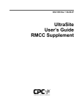
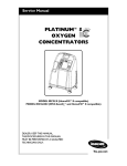
The RMCC consists of a rugged steel enclosure containing a processor board and Power Interface Board (PIB).
The Processor Board (Figure 2-1) contains the LCD
screen, the main processor, and the memory chips that hold
all the code required to operate the RMCC and the data entered at the front panel or through UltraSite. The Processor
Board is mounted on the door of the enclosure and is connected to the PIB with a ribbon cable. The PIB (Figure 22) contains all power and network connections required to
power the RMCC and drive the network, and is attached to
the rear wall of the enclosure.
• Building Control Unit (BCU)
• Building Environmental Control (BEC)
• Store Environmental Control (SEC)
Data Logging
• Intelligent Data Logger (IDL)
CPC REFLECS controllers are designed to perform
three specific tasks: system control, system monitoring,
and data storage. Each controller—depending on its soft-
RMCC I&O Manual
Hardware Overview • 2-1
2.2.
10
9
Input Communication
Boards
8
1
2
7
To properly interact with any environmental control
system, the REFLECS requires constant, accurate system
information. CPC provides this information to the REFLECS through a series of input communication boards.
Except for boards designed to supply both input and output
functions, the 16AI Communication Board is the only input
board used by CPC.
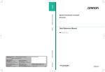
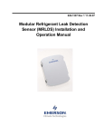
2.2.1.
The 16AI Analog Input Board is a general purpose input board capable of receiving an input signal through any
of 16 two-wire input connections. To function, the 16AI
must be connected through the RS485 I/O network to the
REFLECS. When properly installed, the board receives either digital or analog data from sensors wired to any of the
16 input connections located on the board. Input definition
screens within the REFLECS allow the user to define each
input for refrigeration control.
6
3
4
1
2
3
4
5
6
16AI Board
5
LEGEND
7 Ribbon Cable Connection to Power
LCD Screen Contrast Dial
Interface Board
Main Processor Chip
Ribbon Cable Connection to Keypad
8 RAM Battery
Flash Memory Chips
9 Clock Battery
Manufacture Date
10 Network Baud Rate Dip Switch
RAM Chips
A maximum of sixteen 16AIs may be connected to
an RMCC through the RS485 COM A and D networks.
26502005
Figure 2-1 - REFLECS Processor Board
Within a refrigeration system, the 16AI may be connected to temperature, humidity, or dew point sensors and
pressure transducers, liquid level indicators, and refrigerant
leak transducers.
The 16AI Board is designed with several features that
make it easy to install, wire, and configure. These main
user interface features are shown in Figure 2-3.
Figure 2-3 - 16AI Analog Input Board
Figure 2-2 - Power Interface Board
2-2 • Input Communication Boards
026-1102 Rev 4 08-12-99
2.3.
Output Communication
Boards
because of its straightforward design. Several of these features are shown in Figure 2-4.
When a REFLECS receives data from the 16AI board,
it interprets that information based on current stored set
points. System changes required as a result of this examination are then made through one of several output communication boards. CPC offers four different output boards for
refrigeration system control: 1) 8RO, Relay Output Board,
2) 8RO FC, Form C Relay Output Board, 3) 4AO, Analog
Output Board and 4) 8DO, Digital Output Board.
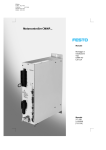
2.3.1.
8RO Board
The 8RO Relay Board is a general-purpose board capable of supplying an output signal through any of eight standard contact relays.
Figure 2-4 - 8RO Relay Output Board
A maximum of sixteen 8ROs and 8RO-FCs may be
connected to an RMCC through the RS485 COM A and
D networks.
To function, the 8RO board must be connected through
the RS485 I/O network to the REFLECS. When properly
installed, the 8RO receives an electrical impulse from the
REFLECS, which either opens or closes any of eight contact relays. Output definitions within the REFLECS software allow the user to configure the 8RO board to interact
with any refrigeration system component.
The 8RO board is the direct link between the REFLECS
and refrigeration system component operation. Information
gathered by the controller from the 16AI board or 8IO
board is checked against current stored set points. If differences in the received input data and the set point information are detected, a signal is either sent to the proper 8RO
relay, or an existing signal is discontinued. Through the use
of this relay signal, refrigeration control functions that can
be properly maintained by a simple contact closure sequence are effectively operated by the REFLECS.
2.3.2.
8RO Form C Board
A maximum of sixteen 8ROs and 8RO-FCs may be
connected to an RMCC through the RS485 COM A and
D networks.
The 8RO Relay Output Board with Form C contacts
(Figure 2-5) is identical in function to the standard 8RO
Relay Output Board, except that it uses relays with form C
contacts and does not use fail-safe jumpers (wiring the contacts as either normally open or normally closed creates the
fail-safe condition). The 8RO-FC is slightly larger than the
standard 8RO; therefore, specific mounting instructions for
the 8RO-FC provided in Section 3.2., I/O Boards and Enclosures, should be used.
Like the 16AI input board, the 8RO board is easily installed and operated within the CPC network environment
Figure 2-5 - 8RO-FC Relay Output Board with Form C Contacts
RMCC I&O Manual
Hardware Overview • 2-3
2.3.3.
4AO Analog Output Board
Three 4AOs may be connected to an RMCC
through the RS485 COM A and D networks.
The 4AO Analog Output Board (Figure 2-6), is configured with four analog output connections that provide a
variable voltage signal to any of four variable speed devices that may be controlled by a single REFLECS.
Figure 2-7 - 8DO Digital Output Board
2.4.
Special Purpose
Communication Boards
Special purpose communication boards are boards that
either possess greater capabilities than standard input and
output boards, or combine the features of both input and
output boards into a single package.
2.4.1.
Figure 2-6 - 4AO Analog Output Board
2.3.4.
8DO Digital Output Board
Up to two 8DOs may be connected to an RMCC
through the RS485 COM A and D networks.
The 8DO digital output board (Figure 2-7) is similar to
the 8RO board, except that instead of a relay that closes on
and off, each output generates either a high (12VDC) or
low (0VDC) signal. The 8DO has eight outputs which may
pulse up to 150mA at 12VDC. The 8DO’s primary functions are to control anti-sweat heaters.
2-4 • Special Purpose Communication Boards
8IO Board
When programming the REFLECS, the 8IO must
be listed as one 16AI board and one 8RO board.
The 8IO combination input and output board is a communication board designed to provide input and output
functions within the same board when space restrictions do
not allow for installation of dedicated boards. Like the
16AI and the 8RO, the 8IO must be connected to the REFLECS to perform input retrieval and output transmission
functions. The 8IO has input and form C relay output connections for monitoring of sensors and control of loads.
Since the 8IO has no memory capability, the hand-held terminal jack is removed from the board. The 8IO is shown in
Figure 2-8.
026-1102 Rev 4 08-12-99
system reading falling outside of these set points is detected
by the REFLECS, a signal is sent to the alarm panel, which
in turn emits an alarm signal and displays the alarm information on the notification screen. Other features of the
alarm panel provide the user with additional information
and capabilities:
• Alarm reset
• Date and time adjustment
• Storage of twenty separate alarms
• Audible annunciation can be set to either pulsed or
continuous mode
• Interfaces with existing facility alarm system
• 25-pin parallel printer interface port.
Wiring of the alarm panel to the REFLECS is discussed
in Section 5.3., COM B Wiring.
4
5
Figure 2-8 - 8IO Combination Input/Output Communication
Board
1
2.4.2.
Case Controller
3
2
CPC offers a variety of case controllers depending on
the valve control approach being used. Because of this variety, and the multiple power modules that are available, a
complete overview of case control is provided in Section 5,
Case Control.
1 Date/Time Button
2 Screen Scroll Buttons
3 Alarm Reset Button
LEGEND
4 LED Power Indicator
5 LCD Alarm Screen
6 LED Alarm Indicator
Figure 2-9 - 485 Alarm Panel
2.5.
485 Alarm Panel
One of the most important requirements of any network
environment is its ability to notify personnel of system failures or possible problems. The REFLECS is designed with
sophisticated logging, graphing, notification, and alarming
features that put system data at the fingertips of the service
technician or store manager. However, no network is complete without the basic ability to provide annunciated
alarms in the event of serious system problems.
CPC uses the 485 Alarm Panel (Figure 2-9) to accomplish this task. The 485 Alarm Panel is linked to all REFLECS Controllers through the RS485 COM B Host
Network. Although the alarm panel has many features that
make it a powerful notification tool, the primary and most
important function of the alarm panel is to receive signals
from the REFLECS and deliver an alarm annunciation.
The REFLECS constantly compares real time system
conditions against user-defined alarm set points. When a
RMCC I&O Manual
Hardware Overview • 2-5
2.6.
Hand-Held Terminal
The Hand-Held Terminal (HHT), shown in Figure 210, connects directly to the RJ11 jack on a case controller
and is used to make set point and setup adjustments during
system start-up or for routine or emergency maintenance.
The HHT displays several screens for viewing refrigeration
system status, making control set point adjustments, and
bypassing loads on or off. Set point changes made through
the HHT are transferred to the RMCC by the case controller and overwrite any existing set points.
Figure 2-11 - RS232 Bus Amplifier
Figure 2-10 - Hand-Held Terminal
2.7.
Remote Communication
2.7.1.
RS232 Bus Amplifier
The RS232 Bus Amplifier (P/N 812-1800), shown in
Figure 2-11, is used to connect CPC controllers together as
an integrated communication system. Communication
problems sometimes associated with large control systems—such as limited cable lengths, data rate limitations,
and terminal and modem communication interference—are
eliminated through the use of the RS232 Bus Amplifier.
2.7.2.
Modems
To communicate with a site from a remote location, the
network must be connected to a modem directly, or through
the RS232 Bus Amplifier. CPC supplies a standard 14400
fax/9600 data modem (P/N 370-9600) for use with the REFLECS network.
The REFLECS and CPC’s RS232 Remote Communication Network are designed to connect to and be compatible with most modems in use today. Remote
communication screens allow the user to define modem
type, baud rate settings, automatic dial-out functions, and
auto-polling.
2.7.3.
UltraSite™
Remote communication with a site controlled by the
REFLECS is accomplished using UltraSite, CPC’s remote
communication software package. UltraSite is a
Microsoft® Windows™-based program that uses animated
graphics, icon buttons, and tabular and graphical data to
display real-time conditions of any site.
UltraSite accesses any site controller through the onsite modem, and, if present, the RS232 Bus Amplifier. All
commands available through the front panel of the REFLECS may be accessed through UltraSite using pop-up
dialog boxes that duplicate information displayed on the
screen of the controller. Changes made to set points in the
dialog boxes are immediately transferred to the unit. Control of the system using the new parameters is instantaneous.
2-6 • Hand-Held Terminal
026-1102 Rev 4 08-12-99
Although most users will make alterations to the system
using the front panel of the REFLECS, individuals who
have access to a laptop computer may find it easier to enter
data—especially during start-up—using UltraSite. A list of
the available UltraSite user guides are listed below:
Part No.
Description
026-1002
UltraSite User’s Guide
026-1003
UltraSite User’s Guide BEC Supplement
026-1004
UltraSite User’s Guide BCU Supplement
026-1005
UltraSite User’s Guide RMCC Supplement
Table 2-1 - UltraSite User’s Guides
RMCC I&O Manual
Hardware Overview • 2-7
3
Hardware Mounting
without removal of any boards inside the enclosure. Figure
3-1 shows the enclosure dimensions and weight.
Hardware Mounting provides all information necessary
to assemble a refrigeration system control network.
3.1.
Refrigeration Monitor and
Case Control
Location
The operating environment of the RMCC is -20°F
(-28.9°C) to 120°F (48.9°C), and 0% to 95% humidity—
non-condensing.
The Refrigeration Monitor and Case Control (RMCC)
is the main controller of the CPC refrigeration control network. As such, it is the component most accessed by store
managers and service technicians. The RMCC should be
located in an easily accessible area, but away from customers and most supermarket employees. Generally, the
RMCC is mounted on the rack by the rack manufacturer.
For information on setting up all components of a standard refrigeration system control network, see Section 10,
System Configuration Guide.
Mounting
The REFLECS is supplied with four mounting holes in
the rear panel of the enclosure. These holes are accessible
Figure 3-1 - RMCC Mounting Dimensions
3.2.
I/O Boards and Enclosures
Location
The 16AI Input Board; 8RO, 8RO-FC, 8DO, and 4AO
Output Boards; and 8IO Combination Input/Output Board
are usually installed within the refrigeration rack or the
condenser by the equipment manufacturer. Therefore, the
installer need only make the necessary connections between the REFLECS, the condenser boards, and the refrigerated cases.
In some instances, an installer may be required to
mount an I/O board. There are no restrictions on the location of these boards; however, for ease of network configuration, it is recommended that the boards be located
adjacent to the REFLECS. If the boards are not located near
the REFLECS, ensure the leg and segment length restrictions described in Section 4.6. are followed. The I/O
boards may be mounted without an enclosure, but should
be mounted in a location that is not easily accessible to
avoid tampering or damage.
Mounting
Single Enclosure Mounting
The Single enclosure is supplied with four mounting
holes in the rear panel of the enclosure. These holes are ac-
RMCC I&O Manual
Hardware Mounting • 3-1
cessible without removal of any boards inside the enclosure. Figure 3-2 shows the enclosure dimensions and
weight. Figure 3-6 shows mounting dimensions for the
8RO and 16AI. Figure 3-7 shows mounting dimensions for
the 8RO-FC.
8RO and 16AI. Figure 3-7 shows mounting dimensions for
the 8RO-FC.
Figure 3-2 - Single Enclosure Mounting Dimensions
Double Enclosure Mounting
The Double enclosure is supplied with four mounting
holes in the rear panel of the enclosure. These holes are accessible without removal of any boards inside the enclosure. Figure 3-3 shows the enclosure dimensions and
weight. Figure 3-6 shows mounting dimensions for the
Figure 3-3 - Double Enclosure Mounting Dimensions
8IO Weather Resistant Enclosure Mounting
The 8IO Combination Input/Output Board is generally
supplied with a weather resistant enclosure.
The weather resistant enclosure is supplied with four
mounting holes on flanges at the top and bottom of the enclosure. These holes are accessible without access to the inside of the enclosure. Figure 3-4 shows the enclosure
dimensions and weight. Figure 3-8 provides mounting dimensions for the 8IO.
3-2 • I/O Boards and Enclosures
026-1102 Rev 4 08-12-99
1. REMOVE THE 16AI OR 8RO BOARD
AND THE INSULATOR FROM THE
SNAP-TRACK.
2. MOUNT THE SNAP-TRACK USING
THE .1875" SLOTS PROVIDED.
3. REINSTALL THE INSULATOR
IN THE SNAP-TRACK.
4. REINSTALL THE 16AI OR 8RO BOARD
IN THE SLOTS IN THE SNAP-TRACK.
Figure 3-4 - Weather Resistant Enclosure
16AI, 8RO, and 8DO Boards Without Enclosures
Mounting
16AI, 8RO, and 8DO boards not supplied with an enclosure are supplied with a snap-track for easy installation.
The insulation sheet and I/O board must be removed from
the track, and the track mounted using the.1875-inch
mounting slots. Figure 3-5 shows this installation procedure. Figure 3-6 provides mounting dimensions for the
16AI and 8RO board.
26501040
Figure 3-5 - 4AO, 8RO, or 16AI Snap-Track Installation
10.00"
4.75"
TYP 2 PL
4.00"
3.50"
16AI/8RO/8DO BOARD
O 0.218"
TYP 6 PL
WEIGHT: 0.50 LB.
26501055
Figure 3-6 - 16AI/8RO/8DO Mounting Dimensions
8RO Form C Boards Without Enclosures Mounting
The 8RO Form C board is slightly larger than the 16AI
and 8RO boards, and is not supplied with a snap-track. If
the 8RO-FC is supplied without an enclosure it is supplied
with.500-inch long metal stand-off dowels which are
RMCC I&O Manual
Hardware Mounting • 3-3
pressed into the mounting holes in the board. Figure 3-7
shows the mounting dimensions for the 8RO-FC.
6.00"
10.00"
4.75"
TYP 2 PL
5.00"
3.50"
8RO-FC BOARD
4.75"
O 0.156"
TYP 6 PL
4.00"
4AO BOARD
WEIGHT: 0.50 LB.
3.50"
O 0.218"
TYP 4 PL
WEIGHT: 0.50 LB.
26501019
26501009
Figure 3-7 - 8RO-FC Mounting Dimensions
8IOs Without Enclosures Mounting
Figure 3-9 - 4AO Mounting Dimensions
8IO boards not supplied with an enclosure are supplied
with.500-inch long metal stand-off dowels that are pressed
into the mounting holes in the board. Figure 3-8 shows the
mounting dimensions for the 8IO Board.
3.3.
485 Alarm Panel
Location
The 485 Alarm Panel is used to alert store personnel to
system problems that require immediate attention; therefore, it is important to mount the panel where it will be visible and easily accessible.
Mounting
The 485 Alarm Panel is supplied with four mounting
holes in the rear panel of the enclosure. These holes are accessible without removal of any boards inside the enclosure. Figure 3-10 shows the enclosure dimensions and
weight.
Figure 3-8 - 8IO/ARTC Mounting Dimensions
4AO Boards Without Enclosures Mounting
4AO boards not supplied with an enclosure are supplied
with a snap-track for easy installation. The insulation sheet
and I/O board must be removed from the track, and the
track mounted using the.1875-inch mounting slots. Figure
3-5 shows this installation procedure for 16AI and 8RO
boards. Installation for the 4AO board is identical. Figure
3-9 provides mounting dimensions for the 4AO board.
3-4 • 485 Alarm Panel
026-1102 Rev 4 08-12-99
4. Replace the front panel.
Figure 3-11 shows the enclosure dimensions and
weight.
Figure 3-11 - RS232 Bus Amplifier Mounting Dimensions
3.5.
Figure 3-10 - 485 Alarm Panel Mounting Dimensions
3.4.
Case Controller
For information regarding locating and mounting case
controllers, refer to Section 5, Case Control.
RS232 Bus Amplifier
Location
Although there are no specific location requirements
for installation of the RS232 Bus Amplifier, it is recommended that the amplifier be located close to the bussed
CPC controllers to prevent data loss over long cable
lengths. It is also recommended that the bus amplifier be located adjacent to the modem and, if present, the local computer terminal to provide easy access to all components
necessary for building control.
In some cases, location of the modem and local terminal will not allow location of the bus amplifier to both the
modem and local terminal and the CPC controllers. Since
data loss is possible when multiple CPC controllers transmit data over long cable lengths, it may be necessary to
connect the CPC controllers to a remote amplifier adjacent
to the controllers, and then connect the remote amplifier to
a main amplifier connected to the modem and local terminal. For complete information on operation of the RS232
Bus Amplifier, refer to 026-1401, RS232 Bus Amplifier Installation and Operation Manual.
Mounting
To mount the RS232 Bus Amplifier,
1. Remove the four front panel screws.
3.6.
Pressure Transducers
CPC uses Eclipse®pressure transducers as pressure
sensing devices. These transducers convert pressure readings to proportional electrical signals between 0.5 and 4.5
volts. The transducer is designed with a 1/8-inch male fine
pipe thread fitting for connection to a standard access fitting. If the fitting is configured with a Schrader valve, this
fitting will have to be removed and replaced with a 1/8-inch
female fitting. Each pressure transducer is supplied with 20
feet of cable for connection to a 16AI input board.
Location
CPC supplies three pressure transducers: 0-100 lb. for
suction pressure, 0-200 lb. for oil pressure, and 0-500 lb.
for discharge pressure. Each is generally installed on the
system by the equipment manufacturer. If a transducer
must be added to the system, consult the refrigeration
equipment manufacturer for proper location.
Mounting
In high-humidity environments, mount the transducer
so that the cable is at the bottom or side. This prevents creating a moisture trap. However, if pressure media might
freeze, mount the transducer with the pressure port pointing
down.
2. Remove the front panel (with circuit board attached).
3. Mount the empty amplifier body, with the power
connection cut-out down.
RMCC I&O Manual
Hardware Mounting • 3-5
3.7.
Temperature Sensors
3.7.1.
Outside (Ambient) Temperature
Sensor
Application
Location
Sensor Type
Condenser Outlet (Drop Leg)
High Temperature Bullet
Liquid (Manifold)
Pipe Mount
Suction Temperature
Pipe Mount
The outside or ambient temperature sensor should be
located on the north side of the building, preferably under
an eave to prevent sun-heated air from affecting the temperature at the sensor.
Discharge Air
Bullet
Ambient Temperature (Outside)
Bullet
Condenser Sump
Insertion Probe
Mounting
Defrost Termination
Bullet
The temperature sensor may be mounted using any
standard tubing clamp. CPC also offers an aluminum cover
and clamp which may be mounted as shown in Figure 3-12
(fasteners are not provided).
Table 3-1 - Sensor Application and Type
Mounting Bullet and Pipe Mount Sensors
Bullet or pipe mount sensors mounted on refrigerant
lines should be secured with a Panduit low temperature cable tie, number PLT2S-M120, or equivalent. For pipe
mount sensors, the curved surface should be placed against
the pipe and the tie should be positioned in the groove on
the top surface of the sensor. A second tie should be used
to secure the lead to the pipe for additional support.
Sensors located on refrigerant lines should be insulated
to eliminate the influence of the surrounding air. A self-adhering insulation that will not absorb moisture is recommended to prevent ice logging at the sensor location.
Depending on the size of the refrigeration line, the sensor should be positioned as shown in Figure 3-13.
Figure 3-12 - Outside Temperature Sensor with Cover and
Clamp
3.7.2.
Refrigeration System Temperature Probes and Sensors
Location
CPC supplies several temperature monitoring devices
including bullet sensors, pipe mount sensors, immersion
probes, insertion probes, and sensors for high temperature
applications. Each of these sensors is generally installed on
the system by the equipment manufacturer. If a device must
be added to the system, refer to the information supplied
with the device and consult the refrigeration equipment
manufacturer. Table 3-1 lists some typical sensor applications and the sensor or probe most suited for that purpose.
The use of these devices is not limited to these applications,
however. Refer to Table 5-1 for wiring of these device
types.
3-6 • Temperature Sensors
26509022
Figure 3-13 - Sensor Orientation
3.8.
Liquid Level Sensors
CPC supplies both a probe (207-1000) and float (2070100) type liquid level sensor. Each is installed by the refrigeration and equipment manufacturer. Table 5-1 shows
how to wire both kinds of liquid level sensors to a 16AI.
026-1102 Rev 4 08-12-99
When setting up the probe in the RMCC system software, specify the probe as a linear sensor with a gain of 20
and an offset of zero. See Section 7.6.2., Setup and Section
7.6.4., Set Points (for Linear sensor types only) for specific software setup instructions.
3.9.
Leak Detectors
CPC supplies both a refrigerant transducer (809-1550)
and Checkit refrigeration system monitor (508-2000) for
monitoring refrigerant leaks. Each is installed by the refrigeration and equipment manufacturer. If a replacement
transducer or Checkit must be installed in the field, complete installation and operation instructions are available in
either 026-1302, Refrigerant Transducer Installation and
Operation Manual, or 026-1303, Checkit Refrigeration
System Monitor Installation and Operation Manual.
3.10. Power Monitoring
The current transformer, watt-hour transducer, and
transducer power supply are all required to perform power
monitoring. CPC uses standard off-the-shelf configurations
of each of these products. Installation instructions supplied
with the units should be used for both the watt-hour transducer and the transducer power supply. A single current
transformer should be located on each phase of the incoming power supply of the motor room.
3.11. Transformers
Transformers are required for all input and output communication boards and case controllers. The transformer
should be located within 10 feet of the board it is powering,
preferably within the board enclosure. CPC supplies four
types of transformers for standard refrigeration applications: three board transformer, six board transformer, 10
board transformer, and 8IO/ARTC transformer. The multiple board transformers may not be used to power an 8IO or
ARTC.
RMCC I&O Manual
Hardware Mounting • 3-7
4
The REFLECS Networks
depth explanation of CPC network wiring practices is provided in Section 4.4., Wiring.
The REFLECS uses four separate networks:
1. The RS485 Input/Output (I/O) Network (COM
A) connects the controller to the input and output
communication boards.
2. The RS485 Host Bus Network (COM B) connects
multiple controllers to a 485 alarm panel.
3. The RS232 Remote Communication Network
(COM C) connects multiple controllers to a modem,
thus allowing remote communication.
4. The RS485 Input/Output (I/O) Network (COM
D) is an additional I/O network that connects the
controller to the input and output communication
boards.
The following sections provide an overview of the basic network components and their function. Wiring requirements for each of the networks is provided in Section 4.4.,
Wiring.
4.1.
RS485 Input/Output (I/O) Network (COM A and D)
The RS485 Input/Output (I/O) network connects all input and output communication boards together in an open
communication loop. This loop connects the REFLECS to
multiple input and output communication boards, and terminates at the last input or output board on the network.
The term “daisy-chain” is sometimes applied to this open
loop arrangement.
Figure 4-1 - Network Loop Wiring Configurations
4.2.
RS485 Host Network (COM
B)
Similar to the I/O network loop, the host network,
shown in Figure 4-2, also uses an open loop configuration.
The primary function of the Host Network Loop is to allow
single or multiple REFLECS Controllers to be connected
together to one common 485 Alarm Panel. The Host Network is always labeled as COM B on the REFLECS. Input
and output boards cannot be connected directly to the host
network.
The REFLECS is configured to monitor and control
two separate RS485 input/output communication networks. These two networks are labeled as either COM A or
COM D. Each network is capable of supporting up to 31
separate input or output boards, plus the single REFLECS
controller. This means that a single REFLECS can monitor
or control up to sixty-two individual input or output boards.
Figure 4-1 shows the I/O network configurations.
The concept of a loop is critical to operation of the I/O
network. The REFLECS cannot properly interact with the
input and output boards unless the boards are connected
and identified within the confines of the loop. The I/O network is always identified as COM A or COM D on the controller. Input and output communication boards are
configured with a RS485 network connection only, which
can be used to connect the board to either COM A or COM
D.
In addition to the primary loop arrangement, a single
star configuration may be connected to the loop. A more in-
RMCC I&O Manual
Figure 4-2 - RS485 Host Communication Network (COM B)
4.3.
RS232 Remote Communication Network (COM C)
The RS232 Remote Communication Network connects
single or multiple REFLECS Controllers to a modem to
provide remote access using a remote communication software package. In some configurations, an RS232 Bus Amplifier may be installed to improve transmission rates and
The REFLECS Networks • 4-1
overall data quality. Like the host network, input and output boards cannot be connected directly to the remote communication network. Figure 4-3 shows a typical remote
communication network layout.
Figure 4-3 - RS232 Remote Communication Network (COM C)
4.4.
Wiring
4.4.1.
Overview
All CPC I/O and host bus communication components
(COM A and D, and COM B) have been designed to conform to RS485 standards. Remote communication components (COM C) have been designed to conform to RS232
standards. When wiring CPC components together, it is
necessary to follow the rules and requirements specified in
this section to ensure proper communication between network devices and effective control of refrigeration control
equipment. Unless noted, all information in this section
pertains to COM A, B, C, and D networks. Information
provided in Section 3, Hardware Mounting, conforms to
these requirements.
4.5.
Legs and Segments
A leg is defined as a cable running between two devices
such as two communication boards, or a REFLECS unit
and a communication board. A segment is defined as the total combined length of all legs connected to one REFLECS
power interface board output connection such as the COM
A or COM D connections. Figure 4-4 demonstrates the relationship between legs and segments.
Figure 4-4 - Relationship Between Legs and a Segment
4.6.
Leg and Segment Wire
Length
A single segment connected to COM A, B, or D may
not exceed 4000 feet. Therefore, the combined length of all
legs in a single segment may not exceed 4000 feet. This
length restriction includes the length of legs in a single star
configuration described in Section 4.9., Star Configurations.
A single segment connected to COM C may not exceed
2500 feet.
4.7.
Number of Devices per Segment
A single segment beginning with a REFLECS controller may have no more than 31 additional devices. A device
is considered to be any controller, board, or alarm panel.
There are restrictions to the number of each board type that
may be connected to the COM A and D networks.
No more than sixteen 8ROs or 8RO-FCs, sixteen
16AIs, three 4AOs, and two 8DOs may be connected to
both the COM A and COM D networks at the same time.
In addition, an 8IO board must be listed as one 16AI and
one 8RO.
4.8.
Daisy Chains
Except for the single star configuration described below, all devices in a segment must be connected in an open
loop or “daisy chain” configuration. A daisy chain must
start with the first device in the segment and continue to the
last device. Branching from a device in the middle of the
segment is prohibited. Figure 4-5 demonstrates correct and
incorrect daisy chain configurations.
4-2 • Wiring
026-1102 Rev 4 08-12-99
I/O BOARD
The purpose of the jumpers is to indicate the two ends,
or termination points, of the segment. If a segment contains
a star, the hub of the star must be one of the segment termination points. The other termination point in the star configuration is the longest leg contained in the network.
I/O NETWORK
CPC
CONTROLLER
LEG
END OF SEGMENT
CORRECT LOOP
CONFIGURATION
INCORRECT LOOP
CONFIGURATION
26513037
Figure 4-5 - Correct and Incorrect Loop Configurations
4.9.
If a device is at either end of a segment in a daisy chain
configuration (Figure 4-7), or if the device is the hub of a
star configuration (Figure 4-8), the terminating resistance
jumpers must be set in the up position. All other devices in
a segment should have their jumpers set to the down position. No segment shall have more than two devices with the
terminating resistance jumpers in the up position.
Star Configurations
Within a single segment, a single star branching from a
single device is allowable. A star is multiple devices connected to a single device within a segment. The device from
which the star extends is called the hub. The legs within a
star may not exceed 100 feet. No more than one star in a
single segment is permitted. Star configurations are not
permitted on the COM B, Host, and COM C, Remote Communication, networks. Figure 4-6 shows correct and incorrect star configurations.
Figure 4-7-Terminating Jumpers for a “Daisy Chain”
Configuration
Figure 4-6 - Correct and Incorrect Star Configurations
4.10. Terminating Resistance
Jumpers (COM A, COM B,
and COM D Only)
Each device that may be connected to a network segment has a set of terminating resistance jumpers (one jumper for each wire lead). These jumpers are always labeled
JU1, JU2, and JU3 for COM A. COM B jumpers are always labeled JU4, JU5, and JU6. COM D jumpers are always labeled JU9, JU10, and JU11.
RMCC I&O Manual
Figure 4-8-Jumper Settings for Star Network
The REFLECS Networks • 4-3
4.11. Network Dip Switches and
Rotary Dials (COM A and D
only)
Each device that may be connected to a segment has either a network dip switch or rotary dials that provide a
unique identifier for each device on the network. Devices
on a segment may numbered in any order; however, gaps
or omissions in the numbering sequence are not permitted.
As an example, if a segment contains four devices, then
board addresses one, two, three, and four must be used;
one, two, three, and five would not be permitted.
In addition, when setting network dip switches and dials, both COM A, COM B, and COM D must be considered
together. If the last device on COM A is numbered five,
then the first device on COM D must be numbered six.
The REFLECS automatically identifies the board types
on the network; therefore, boards that are the same type are
numbered together. For example, if a segment contains
four 16AI boards and five 8RO boards, the 16AIs are numbered one, two, three, and four; and the 8ROs are numbered
one, two, three, four, and five. Figure 4-9 provides a graphic representation of board numbering. Actual dip switch
and rotary dial setup is described fully in Section 5.8.1.1.,
Dip Switches.
rate setup is described fully in Section 4.14., Baud Rate
Settings.
4.13. Network Settings
For all boards, except 8IO boards, the network dip
switch labeled S1 (or S3 for the 16AI board) is used to set
the unique board number of the unit and the baud rate. The
8IO uses rotary dials to set the board number of the unit.
4.13.1. Network Addresses
Board numbering is accomplished using the first five
rockers on dip switch S3 on the 16AI board, the first five
rockers on dip switch S1 on the 8RO and 8RO-FC boards,
and two rotary dials on the 8IO board.
Dip Switches
Each of the first five rockers of either S1 or S3 is given
a value which is twice as large as the value for the rocker to
the left of it. The first rocker is given a value of one. With
these five rockers, a board may be given any value between
1 and 31; however, network restrictions limit the actual
number of boards that may reside on both the COM A and
COM D networks at one time. These restrictions are given
in Section 4.7., Number of Devices per Segment. Use Figure 4-10 to determine the switch settings for 16AI, 8RO,
and 8RO-FC boards.
If a pulse type input is connected to a 16AI Board with
software older than version E.02, the input must be connected to point one, and rocker number eight on the board’s
network dip switch and must be configured to the ON or up
position.
BAUD RATE
ADDRESS
PULSE INPUT
2
1
BOARD 1
1
Figure 4-9 - Network Device Numbering
2
3
4
5
6
8
1
2
2
3
4
5
6
8
1
3
4
5
6
5
6
8
3
4
5
6
2
8
7
1
2
3
4
5
6
4
5
6
BOARD 4
7
8
2
3
4
5
6
8
1
2
3
4
5
6
1
2
3
4
5
6
2
1
2
7
8
1
2
7
1
2
3
4
5
6
7
1
2
6
7
8
3
4
5
6
7
8
3
4
5
6
7
8
ON
1
ON
5
BOARD 12
8
BOARD 15
8
4
ON
BOARD 11
8
3
BOARD 8
7
ON
ON
1
BOARD 7
7
BOARD 14
8
3
ON
BOARD 10
7
BOARD 13
2
1
8
BOARD 3
7
ON
1
7
ON
BOARD 9
2
6
BOARD 6
7
ON
ON
4
ON
1
5
ON
BOARD 5
All networks (COM A, B, C, D) have specific baud rate
requirements; however, only COM A and COM D require
manual setting of the baud rate dip switch. Currently, the
baud rate dip switch in network components may be set at
either 4800, 9600, 19,200, and 38,400. Setting of the baud
rate is accomplished using switch S1 on the REFLECS processor board, the RS485 alarm panel board, and 4AO, 8RO,
and 8RO-FC output boards; and switch S3 on the 16AI input board. The COM B baud rate is preset on the REFLECS
and 485 Alarm Panel dip switch S1 at 4800. The 8IO board
automatically adjusts to the required baud rate. Actual baud
3
ON
1
4
BOARD 2
7
ON
ON
4.12. Baud Rate Dip Switches
(COM A and D only)
3
2
3
4
5
6
7
BOARD 16
8
3
4
5
6
7
8
ON
26501036
Figure 4-10 - Network Address Settings for Dip Switch S1 or S3
on I/O Boards
Numbering 8IO Boards
The 8IO board uses rotary dials to set the network address instead of dip switches. The rotary dial S1 is used to
define the output portion of the board. Therefore, the board
may only be defined as board 1 through 9. Likewise, dial
4-4 • Network Dip Switches and Rotary Dials (COM A and D only)
026-1102 Rev 4 08-12-99
S2 is used to define the input portion of the board and may
be set from 1 to 9.
LED Indicator Lights
Each board contains a green LED Power Indicator Light.
This light indicates whether or not the board is receiving
power. It is also a good indication if the board is on-line
when the LED pulses.
4.14.4. COM C
The COM C baud rate setting is established within the
remote communications screens in the RMCC and is related
to the speed of the modem being used at the store. The
RMCC can communicate at 300, 1200, 2400, and 9600
baud. It is recommended that a baud rate of 9600 be used for
remote communication.
4.14. Baud Rate Settings
The COM A and D networks may be set to either 4800,
9600, 19,200, or 38,400 baud. Positions one and two of the
dip switch located on the processor board of the RMCC are
used to set the baud rate. A different baud rate setting may
not be set for the COM A and D networks.
Positions six and seven on dip switch S1 of the 4AO,
8RO, and 8RO-FC, and switch S3 of the 16AI, are used to
set the baud rate for the communication boards. This baud
rate should match the setting for the RMCC. Figure 4-11
shows the possible baud rate settings and dip switch positions for the COM A and D networks.
COM B
BAUD RATE
(PRESET AT 4800)
COM A AND D
BAUD RATE
COM A AND D
BAUD RATE
1
1
2
3
4
5
6
7
2
3
4
5
6
7
8
8
REFLECS PROCESSOR
BOARD
4AO, 8RO, AND 8RO-FC
(SWITCH S1)
16AI (SWITCH S3)
9600
4800
19200
Figure 4-12-Baud Rate Dip Switch Settings
4.15. Fail-Safe Dip Switch Settings
CPC uses two fail-safe devices on its output boards: a
dip switch and jumpers. These two devices are used to provide fail-safe operation of equipment in the event of either
power loss or network communication loss. The use of these
devices differs depending on the board or controller.
Boards using Form C contacts do not have fail-safe devices, since the contacts are wired for the position required
during power loss, but have a dip switch which illuminates
the LED relay indicator depending on the contact position.
The 8RO has both a fail-safe dip switch (S2) to force the
contacts open or closed if the network fails, and a jumper for
each output (JU4 through JU11) that forces the contact open
or closed during a power loss. Figure 4-13 shows the possible settings for the dip switch and jumpers.
38400
26501045
Figure 4-11 - Baud Rate Dip Switch Settings
4.14.1. Case Controllers
If using case controllers, the baud rate setting for COM
A and D must be set to 19,200 since the baud rate for the case
controller is hard-coded at 19,200. Refer to Section 4.12.,
Baud Rate Dip Switches (COM A and D only), for more information.
4.14.2. 8IO
Baud rate settings for the 8IO board are automatically
adjusted by the board based on the baud rate setting of the
RMCC. The 8IO and ARTC can communicate at baud rates
between 4800 and 38,400 baud.
4.14.3. COM B
The COM B baud rate is preset on the RMCC and 485
Alarm Panel dip switch S1 at 4800 baud since the 485 alarm
panel can only communicate at 4800 baud.
RMCC I&O Manual
Figure 4-13 - 8RO Board Fail-Safe Dip Switch and Jumper
Settings
The ARTC, 8IO, and 8RO-FC have a dip switch (S2)
which indicates the state of the relay (NC or NO). When the
relay is set normally closed, the appropriate LED relay indicator (one through eight) is illuminated. Dip switch rockers
one through eight should be set to the up position if the relay
is wired normally closed and down if the relay is wired normally open.
The REFLECS Networks • 4-5
5
Communication and
Power Connections
This section describes how to wire the CPC refrigeration control system. Information is provided for the REFLECS and all sensors, alarm panels, modems, loads, and
output functions.
5.2.
COM A and D Wiring
Connect the three-wire COM A or COM D network cable to the REFLECS and I/O board 485 network connections as shown in Figure 5-1.
POWER INTERFACE BOARD
All wiring schemes shown in this section conform to
the requirements outlined in Section 5.1., Wiring Specifications.
TB1
+A
RS485
0V
COMA
TB2
-A
+B
POWER
IN
RS485
0V
POWER
ON
-B
COMB
COMC
GND NEU HOT
COMD
POWER
AC1 0V AC2
Wiring Specifications
All CPC I/O and host bus communication components
(COM A and D, and COM B) have been designed to conform to RS485 standards. Remote communication components (COM C) have been designed to conform to RS232
standards. When wiring CPC components together, it is
necessary to follow the rules and requirements specified in
this section to ensure proper communication between network devices and effective control of refrigeration equipment. Unless noted, all information in this section pertains
to COM A, B, C, and D networks. Information provided in
Section 5, conform to these requirements.
Network wiring must meet or exceed the following
specifications:
RS485 (COM A, B, and D)
N E T
5.1.
+485
16AI/8RO/8IO/ARTC
0V
-485
OTHER
BOARDS
COMMUNICATION
PORT
26513032
26513032
Figure 5-1 - COM A Network Connections
5.3.
COM B Wiring
Connect the three-wire COM B network cable to the
REFLECS controllers and 485 Alarm Panel as shown in
Figure 5-2.
.
• Shielded twisted pair
• 18 - 24 AWG wire
• 31 pf/ft maximum capacity between signal wires
• 59 pf/ft maximum capacity between signal and
shield
• 120 ± 50 ohm nominal impedance
• Belden part number 8641 (for plenum installations:
82641 or 88641)
Figure 5-2 - COM B Network Connections
RS232 (COM C)
• Shielded
• 22 AWG wire
• 23 pf/ft max cap. between signal wires
• 41 pf/ft max cap. between signal and shield
• Belden part number 8771
RMCC I&O Manual
Communication and Power Connections • 5-1
5.4.
2.
Jumper 3 to 9 - Place a jumper between terminals 3 and 9.
3.
Inverter Reset Setup - To allow the RMCC to
automatically reset the inverter, connect terminal 9 to one contact of the defined INV(x)
RESET relay (where X equals the group
number of the compressor). Connect the other contact to the compressor relay (see step
4). The INV RESET relay must be set up in
the system software (see Section 7.9.2., Output Definitions).
4.
Compressor Relay - Connect terminals 7 and
12 to one contact of the defined CMP(xx) relay (where XX equals the compressor number). Connect the other contact of the relay to
the VS Alarm relay (see step 4). The CMP relay must be set up in the system software (see
Section 7.9.2., Output Definitions).
5.
4AO Analog Output - A 0-10 VDC signal
from a 4AO board determines the RPM of the
variable-speed compressor. Wire the positive
terminal of this 4AO point to terminal 27 on
the inverter’s contact strips. Wire the negative terminal to terminal 24. The 4AO board
and point address must be set up as a variable-speed compressor output (VS COMP 1 VS COMP 4) in the system software (see
Section 7.9.2., Output Definitions).
6.
External Fault - Place a jumper across terminals 25 and 26.
7.
Fault Input - The Fincor® inverter sends a
signal to a 16AI when an inverter fault occurs. Wire the 16AI point to terminals 30 and
32 on the inverter. The 16AI board and point
address must be set up as an inverter alarm
(VS INVALM) input in the system software
(see Section 7.9.1., Input Definitions).
COM C Wiring
Connect the three-wire COM C network cable to the
REFLECS controllers and modem as shown in Figure 5-3.
Figure 5-3 - COM C Network Connection
5.5.
Fincor® Inverter Wiring
Fincor® brand inverters may be used to power variablespeed compressors. The following sections show how to
set up a Fincor® inverter to work with REFLECS I/O
boards.
Wiring is as shown in Figure 5-4. The terminal strips
shown in the bottom of Figure 5-4 diagram correspond to
the terminal strips in the lower right corner of the inverter’s
control board. Consult the Fincor® user’s manual for more
information about these terminals.
Dip Switches
Figure 5-5 shows how dip switches JD and JE on the
inverter control board must be set. Jumper JD must be set
to the ENABLE position to allow the RMCC to control the
inverter. Jumper JE must be set to the DISABLE position
Figure 5-4 - Fincor Inverter Control Wiring
Fincor® Inverter Wiring Procedure
1.
E-STOP - Terminals 1 and 2 are the inverter’s emergency stop (E-STOP) contacts.
When this connection is open, the inverter
will be overridden off. If desired, terminals 1
and 2 may be wired to a normally closed 8RO
relay so that the RMCC may be configured to
stop the inverter when necessary. Otherwise,
place a jumper between these terminals.
5-2 • COM C Wiring
026-1102 Rev 4 08-12-99
to disable the FWD, REV, and JOG keys on the inverter
keypad.
5.6.
Sensor and Transducer Wiring
Table 5-1 shows some typical sensor and transducer
connections.
For a complete list of hardware and software setup instructions, refer to Appendix B: Sensor Hardware/Software Setup Table.
Figure 5-5 - Fincor Inverter Dip Switch Settings
P/N
Various
Sensor
Temp Sensors
and Probes
Connect to
Input Point
by Board
Type
Wiring
16AI-Any
Available Point
8IO-Any Available Input Point
ARTC-Any
Temp or Aux
Input
1. Connect one lead to the odd numbered terminal and the other lead to the even numbered
terminal (polarity insensitive).
2. Set input dip switch up.
Various
Digital Sensors
(Klixons, Sail
Switches, etc.)
16AI-Any
Available Point
1.Connect one lead to the odd
numbered terminal and the other
lead to the even numbered terminal (polarity insensitive).
8IO-Any Available Input Point
2.Set input dip switch up.
ARTC-An Aux
Input
800-1100
800-1200
800-1500
Pressure Transducers (Eclipse)
100, 200, 500
lb. ratings
16AI-Any
Available Point
8IO-Any Available Input Point
ARTC-An Aux
Input
1. Connect RED power wire
to +5VDC supply on
input board.
2. Connect WHITE signal
wire to even numbered
terminal.
3. Connect BLACK ground
wire to odd numbered terminal.
4. Connect the bare
SHIELD wire to odd
numbered terminal.
5. Set input dip switch
down.
Table 5-1 - Sensor Wiring
RMCC I&O Manual
Communication and Power Connections • 5-3
P/N
800-0100
800-0200
800-0500
Connect to
Input Point
by Board
Type
Sensor
Pressure Transducers (Standard) 100, 200,
500 lb. ratings
16AI-Any
Available Point
8IO-Any Available Input Point
ARTC-An Aux
Input
Wiring
1. Connect RED wire to
+12VDC source on input
board.
2. Connect WHITE signal
wire to even numbered
terminal.
3. Connect BLACK ground
wire to odd numbered
terminal.
4. Connect the bare
SHIELD wire to odd
numbered terminal.
5. Set input dip switch
down.
203-5750
Relative Humidity Sensor
16AI-Any
Available Point
8IO-Any Available Input Point
ARTC-An Aux
Input
1. Wire the “P” sensor terminal to 12VDC supply on board.
2. Wire the “GND” sensor terminal to odd numbered terminal.
3. Wire the “OUT” sensor terminal to even numbered terminal.
4. Jumper sensor terminal “N” to sensor terminal “GND”.
5. Set input dip switch down.
206-0002
Light Level
16AI-Any
Available Point
8IO-Any Available Input Point
ARTC-An Aux
Input
1. Wire GREEN
ground wire to odd
numbered terminal.
2. Wire YELLOW
and RED signal
wires to even
numbered terminal.
3. Wire the POWER
wire to a +12VDC
source on input
board.
4. Set input dip
switch down.
Table 5-1 - Sensor Wiring
5-4 • Sensor and Transducer Wiring
026-1102 Rev 4 08-12-99
P/N
207-0100
Sensor
Analog Liquid
Level
Connect to
Input Point
by Board
Type
16AI-Any
Available Point
8IO-Any Available Input Point
Wiring
1. Connect RED power
wire to +12VDC
source on input
board.
2. Connect BLACK
ground wire to odd
numbered terminal.
3. Connect GREEN signal wire to even numbered terminal.
4. Set input dip switch
down.
Refrigerant
Level Transducer (Hansen
Probe)
16AI-Any
Available Point
8IO-Any Available Input Point
BLACK (GND)
1. Wire BLACK
ground wire from
“GND” sensor terminal to odd numbered board
terminal.
GREEN (SIGNAL)
TO ODD # TO EVEN #
TERMINAL TERMINAL
2. Wire GREEN signal wire from “SIGNAL” sensor
terminal to even
numbered board terminal.
RED (POWER)
207-1000
TO +12 VDC
ON BOARD
3. Wire RED power
wire from
“POWER” sensor
terminal to +12VDC
terminal on board.
4. Set input dip switch
down.
203-1902
Dew Point
Probe
16AI-Any
Available Point
8IO-Any Available Input Point
ARTC-An Aux
Input
1. Connect the WHITE and GREEN wires
to AC1 and AC2 power terminals.
2. Connect BLACK ground wire to odd
numbered board terminal.
3. Connect RED signal wire to even numbered board terminal.
4. Set input dip switch up.
Table 5-1 - Sensor Wiring
RMCC I&O Manual
Communication and Power Connections • 5-5
P/N
550-2500
Connect to
Input Point
by Board
Type
Sensor
KW Transducer
550-2550
16AI (E.02 and
Above)-Any
Available Point
Wiring
4-20 mA Output to Input Board
16AIs Below v.
E.02-Pulse
Accumulator
Must be Connected to Point 1
8IO-Any Available Input Point
ARTC-An Aux
Input
1. Wire positive transducer terminal to positive 24VDC supply.
2. Wire negative transducer terminal to odd numbered input terminal.
3. Wire negative 24VDC supply to even numbered input terminal.
4. Place 250Ω resistor across odd and even numbered input terminals.
5. Set input dip switch down.
Pulse Accumulator Output to Input Board
1. If the input board is an 8IO or a 16AI version E.02
or greater, connect the two KWH terminals to the
input point (polarity insensitive)
2. If the input board is a 16AI version less than E.02,
connect the KWH terminals to board point 1. Set
input switch #1 DOWN, and set network switch
#8 UP.
3. Set input dip switch down.
Table 5-1 - Sensor Wiring
5-6 • Sensor and Transducer Wiring
026-1102 Rev 4 08-12-99
5.7.
Power Connection Wiring
ThreeBoard
Power Requirements
Each board used with the RMCC has specific power requirements. These requirements determine how many
boards may be wired to each transformer. Power requirements for each board on the RMCC network are listed in
Table 5-2.
8IO
16AI
amps
.75
P/N
Power
Rating
Six-Board
TenBoard
640-0043
640-0045
640-0048
56 VA
100 VA
175 VA
Figure 5-6-Power Ratings for CPC Transformers
8RO
.25
10
.75
1
VA
18
5.0
15.0
VAC
24
24
24
8
2
6
4
5
PINOUT
Ground
Centertapped
4AO
Centertapped
485 Alm.
10
8
6
8DO
0.5
1.5
VA
10.0
18
Ground
120
Centertapped
8
6
AC1
0V
AC2
2
110 VAC
4
208 VAC
24
Centertapped
5
5
FOR 110 VAC POWER SOURCE
Table 5-2 - Power Requirements
5.7.1.
10
1
2
4
24
AC2
1
amps
VAC
AC1
0V
Power Transformers
FOR 208 VAC POWER SOURCE
26513001
Figure 5-7 - Wiring for 640-0043, Three Board, and 640-0045,
Six Board Transformer
Transformers for powering the input and output boards
should be wired according to Figure 5-7 and Figure 5-8
depending on the number and type of boards being powered.
To select a power transformer for a board or a series of
boards:
1.
Determine what the total VA is for the boards
that will be powered by the transformer.
EX: Two 8IOs (18.0 VA each), and one 4AO
(10.0 VA) boards are to be powered by one
transformer
( 2 × 18VA ) + ( 1 × 10VA ) = 46VA
2.
Use a transformer that has a power rating
higher than the total calculated VA (see Figure 5-6).
EX: Three board transformer (56 VA) is sufficient
56 VA is greater than 46 VA
RMCC I&O Manual
Communication and Power Connections • 5-7
Figure 5-8 - Wiring for 640-0048, Ten Board Transformer
5.7.1.1. Wiring the 16AI, 8RO, 4AO, or 8DO
The 16AI, 8RO, 4AO, and 8DO all require the use of a
center tap. The number of boards that need power will determine the transformer size that is required. (see Section
5.7.1., Power Transformers). It is important that the transformer size match the board’s power requirement.
Figure 5-9 diagrams the wiring for three 16AIs, 8ROs,
4AOs, or 8DOs, or any combination of the four board
types. These boards all use a center tap configuration for
grounding.
Figure 5-9-Wiring for Three 16AIs, 8ROs, 4AOs, or 8DOs or
Any Combination of
5.7.1.2. Wiring the 8IO Board
The 8IO board can be wired for power in three different
ways:
5-8 • Power Connection Wiring
1.
By itself with one transformer for power
(Figure 5-10)
2.
In combination with a or multiple 16AI, 8RO,
4AO, or 8DO boards(Figure 5-11)
3.
On a 24 V AC line with the ground in the sys-
026-1102 Rev 4 08-12-99
tem on either side of the power line or with no
ground in the system at all (Figure 5-12)
0V
0V
-485
+485
+485
AC1 0V AC2
POWER
0V
-485
POWER
AC1 0V AC2
TE N
+485
TE N
8IO
POWER
TRANSFORMER
SECONDARY
16AI/8RO/
4AO/8DO
POWER
TRANSFORMER
SECONDARY
EARTH GROUND
26513095
Figure 5-10-Single 8IO Board Wired to One Transformer
When the 8IO board is used by itself, it is satisfactory
to wire the board with no grounding on either side of the 24
V AC power supply.
-485
TE N
POWER
AC1 0V AC2
8IO
EARTH GROUND
26513094
Figure 5-11-8IO Board Wired in Combination with A or Multiple
16AI, 8RO, 4AO, 8DO
When the 8IO board is wired in conjunction with other
boards, the 8IO board is not grounded through the other
board’s center tap. A separate Earth ground should be run
off of the 8IO.
RMCC I&O Manual
Communication and Power Connections • 5-9
When the 8IO is wired alone, either or neither side of
the power supply may be grounded however, a separate
Earth ground should be made off of the center terminal
(power connection).
5.8.
8IO
5.8.1.
-485
0V
16AI, 8RO,
4AO, 8DO
BOARD
+485
POWER
Network Settings
For all boards, except 8IO boards, the network dip
switch labeled S1 (or S3 for the 16AI board) is used to set
the unique board number of the unit and the baud rate. The
8IO uses rotary dials to set the board number of the unit and
the baud rate is set internally at 9600.
TEN
AC1 0V AC2
24 V AC
POWER
SUPPLY
Network Address
Board numbering is accomplished using the first five
rockers on dip switch S3 on the 16AI board, the first five
rockers on dip switch S1 on the 8RO and 8RO-FC boards,
and two rotary dials on the 8IO board.
EARTH GROUND
OR
5.8.1.1. Dip Switches
Each of the first five rockers of either S1 or S3 is given
a value which is twice as large as the value for the rocker to
the left of it. The first rocker is given a value of one. With
these five rockers, a board may be given any value between
1 and 31; however, network restrictions limit the actual
number of boards that may reside on both the COM A and
COM D networks at one time. These restrictions are given
in Section 4.7., Number of Devices per Segment. Use Figure 5-13 to determine the switch settings for 16AI, 8RO,
and 8RO-FC boards.
8IO
0V
If a pulse type input is connected to a 16AI Board with
software older than version E.02, it must be connected to
input one and rocker number eight on the board’s network
dip switch must be configured ON or in the up position.
-485
+485
POWER
AC1 0V AC2
16AI, 8RO,
4AO, 8DO
BOARD
TEN
24 V AC
POWER
SUPPLY
EARTH GROUND
BAUD RATE
ADDRESS
OR
PULSE INPUT
2
1
8IO
24 V AC
POWER
SUPPLY
BOARD 1
1
2
3
4
5
6
8
POWER
AC1 0V AC2
1
3
4
5
6
2
3
4
5
6
4
5
6
1
2
1
8
BOARD 3
7
8
4
5
6
BOARD 4
7
8
2
3
4
5
6
2
3
4
5
6
1
2
1
2
1
2
1
2
BOARD 7
7
8
1
2
3
4
5
6
7
8
4
5
6
7
8
3
4
5
6
7
8
ON
BOARD 11
8
ON
3
BOARD 8
7
ON
1
8
3
ON
BOARD 10
7
8
1
2
3
4
5
6
7
BOARD 12
8
ON
3
4
5
6
7
8
ON
-485
0V
7
TEN
+485
6
BOARD 6
7
BOARD 9
BOARD 13
1
ON
26513097
Figure 5-12-One 8IO Wired to a 24 V AC Line with a Ground on
Either Side
5-10 • Network Settings
3
ON
1
5
ON
BOARD 5
2
ON
ON
EARTH GROUND
2
ON
1
4
BOARD 2
7
ON
16AI, 8RO,
4AO, 8DO
BOARD
3
2
3
4
5
6
7
BOARD 14
1
8
ON
2
3
4
5
6
7
BOARD 15
8
1
ON
2
3
4
5
6
7
BOARD 16
8
3
4
5
6
7
8
ON
26501036
Figure 5-13 - Network Address Settings for Dip Switch S1 or S3
on I/O Boards
026-1102 Rev 4 08-12-99
Rotary Dials on 8IO Board
The 8IO board uses rotary dials to set the network address in lieu of dip switches. The rotary dial S1 is used to
define the output portion of the board. Therefore, the board
may only be defined as board one through nine Likewise,
dial S2 is used to define the input portion of the board and
may be set from one to nine. Do not select the “0” on the
dial.
5.8.1.2. LED Indicator Lights
Each board contains a LED Power Indicator Light. This
light indicates if the board is receiving power. It also indicates if the board is on-line with the network by sending a
pulsing signal.
5.9.
Fail-Safe and Relay Dip
Switch Settings
set normally closed, the appropriate LED relay indicator
(one through eight) is illuminated. Dip switch rockers one
through eight should be set to the up position if the relay is
wired normally closed and down if the relay is wired normally open.
5.10. Baud Rate Dip Switch
Settings
The ARTC, 8IO, and 8RO-FC have a dip switch (S2)
which indicates the state of the relay (NC or NO). When the
relay is set normally closed, the appropriate LED relay indicator (one through eight) is illuminated. Dip switch rockers one through eight should be set to the up position if the
relay is wired normally closed and down if the relay is
wired normally open.
5.10.1. COM A and D Networks
CPC uses two fail-safe devices on its output boards: a
dip switch and jumpers. These two devices are used to provide fail-safe operation of equipment in the event of either
power loss or network communication loss. The use of
these devices differs depending on the board or controller.
The COM A and D networks may be set to either 4800,
9600, 19,200, or 38,400 baud. Positions one and two of the
dip switch located on the processor board of the RMCC are
used to set the baud rate. A different baud rate setting may
not be set for the COM A and D networks.
Boards using Form C contacts do not have fail-safe devices, since the contacts are wired for the position required
during power loss, but have a dip switch which illuminates
the LED relay indicator depending on the contact position.
Positions six and seven on dip switch S1 of the 4AO,
8RO, and 8RO-FC, and switch S3 of the 16AI, are used to
set the baud rate for the communication boards. This baud
rate should match the setting for the RMCC. Figure 5-15
shows the possible baud rate settings and dip switch positions for the COM A and D networks.
5.9.1.
8RO
The 8RO has both a fail-safe dip switch (S2) to force
the contacts open or closed if the network fails, and a jumper for each output (JU4 through JU11) that forces the contact open or closed during a power loss. Figure 5-14 shows
the possible settings for the dip switch and jumpers.
COM B
BAUD RATE
(PRESET AT 4800)
COM A AND D
BAUD RATE
COM A AND D
BAUD RATE
1
1
2
3
4
5
6
7
2
3
4
5
6
7
8
8
REFLECS PROCESSOR
BOARD
4AO, 8RO, AND 8RO-FC
(SWITCH S1)
16AI (SWITCH S3)
9600
4800
19200
38400
26501045
Figure 5-15 - Baud Rate Dip Switch Settings
5.10.1.1. Case Controllers
If using case controllers, the baud rate setting for COM
A and D must be set to 19,200 since the baud rate for the
case controller is hard-coded at 19,200. Refer to Section
4.12., Baud Rate Dip Switches (COM A and D only), for
more information.
Figure 5-14 - 8RO Board Fail-Safe Dip Switch and Jumper
Settings
5.9.2.
8IO and 8RO-FC
The 8IO and 8RO-FC have a dip switch (S2) which indicates the state of the relay (NC or NO). When the relay is
RMCC I&O Manual
5.10.1.2. 8IO Baud Rates
Baud rate settings for the 8IO board are automatically
adjusted by the board based on the baud rate setting of the
RMCC. The 8IO can communicate at baud rate settings between 4800 and 38,400.
Communication and Power Connections • 5-11
5.10.2. COM B Network
The COM B baud rate is preset on the RMCC and 485
Alarm Panel dip switch S1 at 4800 since the 485 alarm panel can only communicate at 4800 baud.
S2
1
2
3
4
5
6
7
8
ON
5.10.3. COM C Network
The COM C baud rate setting is established within the
remote communications screens in the RMCC and is related to the speed of the modem being used at the supermarket. The RMCC can communicate at 300, 1200, 2400, and
9600 baud. It is recommended that a baud rate of 9600 be
used for remote communication.
Set DOWN for
sensors requiring
voltage
INPUTS 1-8
S1
1
2
3
4
5
6
7
Set UP for
sensors not requiring
voltage
8
ON
INPUTS 9-16
5.11.
Terminating Resistance
Jumper Settings
26501070
Figure 5-16 - Input Type Switches (S1 and S2)
Each device on the network has a set of three terminating resistance jumpers (JU1, JU2, JU3). These jumpers are
critical to network operation. If a device is at the beginning
or end of the COM A or COM D network, or if the device
is at the hub of a star, the terminating resistance jumpers
must be set to the up position. If the device is any where
else on the network, set the jumpers down. Refer to Section
4.10., Terminating Resistance Jumpers (COM A, COM B,
and COM D Only) for more information.
5.12. Input Type Dip Switch
Settings
The 16AI and 8IO Boards have input type dip switches
that are used to establish the type of inputs connected to the
board. On the 16AI, switches S2 and S1 contain all the
rockers that correspond to each of the 16 inputs (shown in
Figure 5-16). On the 8IO, switch S4 contains eight rockers
that represent inputs one through eight.
If a sensor requires voltage to operate, the input type dip
switch rocker must be set to the DOWN position. Sensors
that require no voltage must have their input type dip
switch rockers set to the UP position.
5-12 • Terminating Resistance Jumper Settings
026-1102 Rev 4 08-12-99
6
Case Control Hardware
Overview
lay, and it has a jumper that is set based on whether the
valve is bipolar or unipolar.
6
This section provides complete information for installing and programming all versions of CPC’s case controller.
Information is also given for both the CCB and defrost
power modules, which are designed to provide power within the space restrictions of the refrigerated case. The section should be used in conjunction with the other sections
within this manual to configure a complete refrigeration
control system. Information for controlling refrigerated
cases without case controllers is provided in Section 2,
Hardware Overview, and Section 9, Software Overview.
6.1.
1
2
3
4
5
6
7
8
6.2.
Hardware Description
6.2.1.
Case Controllers
CPC produces two different hardware versions of the
case controller to interact with either a pulse valve or stepper valve.
The pulse valve case controller (Figure 6-1) may be
configured with a second valve relay for simultaneous control of two pulse valves. Control of two valves simultaneously is intended for applications where two evaporators
are being used to refrigerate a single space such as a walkin box cooler. A single pulse case controller is not capable
of controlling two separate cases. The stepper valve case
controller (Figure 6-2) does not have the second valve re-
3
8
10
9
12
11
13
1
2
14
Network Address Rotary Dials
Leak Sensor Input
Frost Sensor Input
Door Switch Sensor Input
Hand-Held Terminal Jack RJ11
Input Cable Connector
Termination Resistance Jumpers
Fan and Light Fail Safe Jumpers
(JU7, JU8)
LEGEND
11 Valve Relay (Plug-In)
12 Fuse 250 V, 5 A, AGC-5, or Equivalent
13 Valve Fuses 250 V, AGC-2 or
Equivalent
14 Output Cable Connector
Lights (12 VDC, 170 Ma max.)
Fan (12 VDC, 170 Ma max.)
Anti-Sweat (12 VDC, 170 Ma max.)
Defrost (12 VDC, 170 Ma max.)
Pulse Valve 1 (24 VAC)
9 Second Valve Output (24 VAC)
10 Optional 2nd Valve Relay (Plug-In)
Introduction
A case controller is typically designed to control all refrigerated case functions including lights, fans, defrost,
anti-sweat, and suction side or liquid side valve control.
4
5
7
26502018
Figure 6-1 - Pulse EEV Case Controller
8
6
5
4
7
3
2
Network Address Rotary Dials
Leak Sensor Input
Frost Sensor Input
Door Switch Sensor Input
Hand-Held Terminal Jack RJ11
Input Cable Connector
Termination Resistance Jumpers
Fan and Light Fail Safe Jumpers
(JU7, JU8)
10
11
1
1
2
3
4
5
6
7
8
9
LEGEND
10 Fuse 250 V, 5 A, AGC-5, or Equivalent
11 Output Cable Connector
Lights (12 VDC, 170 Ma max.)
Fan (12 VDC, 170 Ma max.)
Anti-Sweat (12 VDC, 170 Ma max.)
Defrost (12 VDC, 170 Ma max.)
Pulse Valve 1 (24 VAC)
9 Valve Type Jumper (JU5)
26502022
Figure 6-2 - Stepper EEV Case Controller
Full installation of the case control kit requires five
standard components:
1. Case Controller
2. Applicable Temperature Sensors
3. Input Cable
4. Output Cable
5. Power Module
Items 1 and 2 are supplied as a single kit. The input and
output cables must be ordered separately depending on the
power modules being used.
RMCC I&O Manual
Case Control Hardware Overview • 6-1
Table 6-1 lists the different case controller types and
their part numbers. Table 6-2 lists the available input and
output cable configurations and their part numbers.
Table 6-2 lists the harness configurations and their part
numbers.
Description
Description
Part
Number
Part
Number
Input Cable - Includes coil in and coil out for
one valve, discharge air, defrost termination,
suction valve, and network I/O communication.
335-3151
335-3156
810-3151
Output Cable - Includes lights, fans, antisweat, defrost. For use with non-CPC power
modules (without connectors).
Suction Stepper EEPR Case Controller Kit
(Hussmann)**
810-3152
Output Cable - For use with CPC power modules (with connectors).
335-3158
Suction Stepper EEPR Case Controller (Hussmann) (no sensors)
810-3153
Output Cable - For Sporlan SEI and CDS
valves.
335-3159
Suction Stepper EEPR Case Controller Kit
(CPC)**
810-3154
Table 6-2- Case Controller Cable Harness Part Numbers
Suction Stepper EEPR Case Controller (CPC)
(no sensors)
810-3155
6.2.3.
Second Valve Kit (pulse only). Includes:
510-3130
Liquid Pulse EEV Case Controller Kit*
810-3140
Liquid Pulse EEV Case Controller (no sensors)
810-3141
Liquid Stepper EEV Case Controller Kit*
810-3150
Liquid Stepper EEV Case Controller (no sensors)
Coil Inlet Temperature Sensor (Blue Leads)
Coil Outlet Temperature Sensor (Red Leads)
Solid State Relay
75 VA Transformer
501-1125
501-1126
221-7000
140-0050
Second Valve Kit, without 75 VA Transformer
510-3125
* Includes:
Discharge Air Sensor (Green Leads)
Coil Inlet Temperature Sensor (Blue Leads)
Coil Outlet Temperature Sensor (Red Leads)
** Includes:
Discharge Air Sensor (Green Leads)
501-1122
501-1125
501-1126
Power Modules
In addition to the case controllers, CPC manufactures a
power module for distribution of incoming power to the
controller and electric defrost circuits. The power module
is available with or without circuit protection. See Figure
6-3 and Figure 6-4. The CPC power module configurations and part numbers are listed in Table 6-3. The electrical ratings for the power modules are shown in Table 6-4.
The case controllers may also be installed within the
case in conjunction with an OEM-designed power module.
501-1122
Table 6-1 - Case Controller Part Numbers
6.2.2.
Input and Output Cables
CPC produces a single input cable harness, and three
different output cable harnesses depending on the power
module or valve type being used.
The input cable harness (335-3151) is supplied with a
connector for connection to the case controller, and connector ends which mate to the temperature sensors supplied
with the case controllers.
Figure 6-3 - Case Controller Power Module
The output cable harness may be any of three types. The
full output cable harness is supplied without connectors
(335-3156) for connection to non-CPC power modules, or
with connectors (335-3158) for connection to CPC power
modules, which are supplied with female connectors. A
third output cable harness (335-3159) is provided if a
Sporlan suction stepper unipolar valve is being used.
6-2 • Hardware Description
026-1102 Rev 4 08-12-99
Figure 6-4 - Case Controller Power Module Without Fuse
Protection
Part
Number
Description
120 VAC 1 Phase/240 VAC 3 Phase Defrost, Full Configuration
120 VAC 1 Phase/240 VAC 3 Phase Defrost, No Fuses,
No Fuse Holder
120 VAC 1 Phase/240 VAC 3 Phase Defrost, No Fuses,
with Fuse Holder
240 VAC 1 Phase, Full Configuration
Lights
AntiSweat
Fans
816-3000
Yes
Yes
816-3005
Yes
Yes
Yes
816-3010
Yes
Yes
Yes
Defrost
Yes
816-3100
Yes
Yes
816-3105
Yes
Yes
Yes
816-3110
Yes
Yes
Yes
816-3200
Yes
Yes
816-3205
Yes
Yes
Yes
816-3210
Yes
Yes
Yes
Yes
816-3310
Yes
Yes
Yes
Yes
Yes
Table 6-3 - Power Module Part Numbers
Power Module Output Ratings
Output
Lights
Volts
Normally
Open
Normally
Closed
120 V
20 A
10 A
240 V
6A
3A
120 V
¾ hp
¼ hp
240 V
1½ hp
½ hp
Anti-Sweat
120 V
12 A
240 V
12 A
Defrost
120 V
30 A (1 or 2 pole)
25 A (3 pole)
240 V
30 A (1 or 2 pole)
25 A (3 pole)
Fans
Maximum
Fuse
20 A
15 A
15 A
30 A
Table 6-4 - Power Module Output Ratings
RMCC I&O Manual
Case Control Hardware Overview • 6-3
7
Case Control Installation
7.1.
Case Controller
replaced or installed in the field, it should be located based
on the specific design of the case; however, the following
guidelines are provided to help ensure proper installation..Use Table 7-1 to help ensure that the correct CPC case
control board is being installed.
Generally, the case controller will be mounted within
the raceway or on top of the case. If a controller must be
Valve Type
Manufacturer
Valve Description
Generic
Pulse
Alco
Sporlan
Case Control
Type
CPC Case Control
Board Required
None
P/N 810-3141
W/ Probes*
P/N 810-3140
W/ High Humidity
Probes
P/N 810-3142
Second Valve Kit (Pulse Only)
W/ Coil Inlet Temperature Sensor, Coil Outlet
Sensor, Solid State Relay, & 75 VA Transformer
P/N 510-3130
Second Valve Kit (Pulse Only) W/out 75 VA
Transformer
W/ Coil Inlet Temperature Sensor, Coil Outlet
Sensor, Solid State Relay
P/N 510-3125
Stepper
Liquid Stepper ESV
Valve
None
P/N 810-3151
W/ Probes*
P/N 810-3150
Hussman Suction
Stepper ESR Valve
None
P/N 810-3157
W/ Probes*
P/N 810-3156
CPC (Standard) Suction ESR Valve
None
P/N 810-3159
W/ Probes*
P/N 810-3158
Hussman Suction
Stepper CDS Valve
None
P/N 810-3153
W/ Probes*
P/N 810-3152
CPC (Standard) Suction CDS Valve
None
P/N 810-3155
W/ Probes*
P/N 810-3154
Liquid Stepper SEI
valves
None
P/N 810-3139
W/ Probes*
P/N 810-3138
Stepper
Liquid Pulse
Probe Types Included
*Includes Discharge Air Sensor, Coil Inlet Temperature Sensor, & Coil Outlet Temperature Sensor
Table 7-1 - Required CPC Case Control Boards based on Valve Type and Case Control Type
7.1.1.
Size
The case controller enclosure measures 14.375 inches
long by 3 inches wide by 1.875 inches deep. The cover is
secured to the base plate by two 6/32 lock nuts. The base
has one 0.218 inch mounting hole located at each corner.
7.2.
Power
Do not use the center tap of any transformer to power the CCB. Do not use a single transformer to power a
CCB and another I/O board (16AI, 8RO, etc.).
The case controller should only be used with a Class 2,
24 VAC (50 VA) transformer with no center tap. Wiring of
RMCC I&O Manual
Case Control Installation • 7-1
the case controller to the transformer is diagrammed in
Figure 7-1.
T1
P1
120 VAC
P2
S1
WHITE
S2
GREEN
S3
WHITE
24 VAC
Jumper
Position
CASE CONTROLLER
Figure 7-1 - Case Controller to Transformer Wiring
Output
Load
Up
On
12 VDC
On
Down
On
No voltage
On
Table 7-3 - JU7 and JU8 setting result
7.4.
Jumper Settings
Valve Type Jumper (JU5) (Stepper EEV Only)
Set the valve type jumper (JU5) UP for 24V valves (Alco ESV & ESR Liquid Stepper) and DOWN for 12V valves
(Sporlan SEI Liquid Stepper). See Table 7-2
Set
Jumpers
For
Indicator
Light
26513068
GND
7.3.
down position, wire the fans and lights to the NC connection on the power module relays. See Table 7-3.
ALCO
ESV
Liquid
Stepper
(S/EEV)
Unipolar
(24V)
Alco ESR
Bipolar
(24 V
Only)
Sporlan
SEI
Liquid
Stepper
(S/EEV),
CDS EEPR
Bipolar
(12V)
Unipolar
Unipolar
Bipolar
Baud Rate
The CCB baud rate is hard-coded at 19,200 and cannot
be changed. For networks with case controllers attached,
the baud rate setting for COM A and D on the RMCC
should be set to 19,200. See Section 4.12., Baud Rate Dip
Switches (COM A and D only).
7.5.
Optional Inputs and Outputs
The case controller is configured with optional inputs
for a leak detector, optical frost sensor, and clean/door
switch (non-voltage contact change of state). One optional
output for a second 24 VAC, pulse electronic expansion
valve is provided. If a second valve is used, a valve relay
must be installed as shown in Figure 6-1, Item 10. Wiring
for these connections is shown in Figure 7-2.
Table 7-2 - Valve Type Jumper Settings
See Section 8.3., Valve Control, for valve types available.
Lights and Fans Output Jumpers (JU7 and JU8)
If the lights and fans are wired to the NC connection
of the power module relays, then the relays are de-rated
to 10 amps.
Jumpers JU7 for lights and JU8 for fans define whether
the relay is normally open or normally closed when 12
VDC power is applied. Set the jumpers up for normally
open or down for normally closed. The case controller is
supplied in the normally open configuration and should be
wired to the case controller power module as shown in Figure 5-13 and Figure 5-14. If JU7 and JU8 are set in the
7-2 • Jumper Settings
Figure 7-2 - Case Controller Optional Inputs and Outputs
Wiring
026-1102 Rev 4 08-12-99
7.6.
Cable Harnesses
7.6.1.
Input Cable
module. The schematic diagrams for these cables are
shown in Figure 7-4 and Figure 7-5.
CPC’s case controller input cable harness (335-3151) is
designed for use with either a pulse or stepper valve case
controller. The connector is constructed with 18 AWG color-coded wire with a male end, 20-pin connector for connection to the case controller. Female connectors are
supplied for each of the sensors and wire leads are supplied
for an optional suction valve and the RS485 network. The
schematic diagram for the cable is shown in Figure 7-3.
Figure 7-4 - Output Cable Harness Without Quick Connects
(335-3156) Schematic Diagram
Figure 7-3 - Input Cable Harness (335-3151) Schematic
Diagram
7.6.2.
Output Cables
Full Output Cables
CPC’s case controller full output cable harness without
connectors (335-3156) and with connectors (335-3158) are
designed for use with either a pulse or stepper valve case
controller. The connector is constructed with 18 AWG color-coded wire with a 16-pin, male end connector for connection to the case controller. The 335-3156 output cable is
supplied with wire leads for connection to non-CPC power
modules, while the 335-3158 cable is supplied with an 8pin, male end connector for connection to the CPC power
RMCC I&O Manual
Figure 7-5 - Output Cable Harness With Quick Connects (3353158) Schematic Diagram
Case Control Installation • 7-3
Full Output Cable for Sporlan Suction Stepper Bipolar
Valve
CPC’s case controller full output cable harness (3353159) is designed for use with a stepper valve case controller controlling a Sporlan suction stepper bipolar valve. The
connector is constructed with 18 AWG color-coded wire
with a 16-pin, male end connector for connection to the
case controller, an 8-pin, male end connector for connection to a CPC power module, and a 4-pin female end connector for connection to the Sporlan valve.
The schematic diagram for this cable is shown in Figure 7-6.
CPC
Wire
Color
Pin
#
ALCO
ESV
Liquid
Stepper
(S/EEV)
Unipolar
(24V)
Alco
ESR
Bipolar
(24 V
Only)
Sporlan
SEI
Liquid
Stepper
(S/EEV),
CDS
EEPR
Bipolar
(12V)
Blue
1
Blue
Red
Red
Green
2
Red
Blue
Green
Black/
Yellow
13
Black
Black
Black
Purple/
Red
14
White
White
White
Yellow
16
Yellow
Not Used
Not Used
Table 7-4 - Valve Cable Wire Colors
7.7.
Power Modules
Size
The case controller power module measures 16.25
inches long by 3 inches wide by approximately 3.25 inches
deep. The base plate has one 0.218 inch mounting hole located at each corner.
Figure 7-6 - Sporlan Stepper Valve Output Cable Harness (3353159) Schematic Diagram
Power
Full Output Cable for Alco ESR Valve
The case controller power module should be connected
to a 120 VAC single phase power source. Complete wiring
of the case controller power module is diagrammed in Figure 7-7. Follow all local, NEC, and UL wiring practices
The CCB is designed to use the 24 V version of the
Alco ESR Valve. The 24 V version of the valve has
-24VDC appended to the part number. The ESR valve harness from Alco comes in two versions, with an in-line
molex connector, the CPC harness (P/N 335-3159) can be
used. If the valve is purchased with the in-line molex, the
CPC Output Cable Harness with Quick Connects (3353158) must be used. The connector must be cut off of the
harness and the valve wired according to specifications in
Table 7-4.
Table 7-4 shows the relationship between the CPC output cable colors and the associated valve cable colors.
7-4 • Power Modules
026-1102 Rev 4 08-12-99
7.8.3.
DEFROST HOT
DEFROST HOT
DEFROST HOT
DEFROST OUT
DEFROST OUT
DEFROST OUT
ANTI-SWEAT HOT
FANS HOT
LIGHTS HOT
ANTI-SWEAT OUT
COM
NO
COM
NO
Coil Outlet Sensor (Red Leads)
Proper location of the coil outlet sensor is critical since
valve control is dependent upon accurate measurement of
changes to evaporator discharge gas temperature. The coil
outlet sensor should be located on a horizontal section of
the suction line, near the evaporator outlet. Follow the
mounting instructions listed for the coil inlet sensor. For
orientation of the sensor on the coil, see Figure 7-8.
FANS OUT (NC or NO)
LIGHTS OUT (NC or NO)
2
HOT
3
LINE
4
NEUTRAL
5
6
OUTPUT CABLE
1
7
EARTH GROUND
8
26513067
Figure 7-7 - Case Controller and Defrost Power Module Wiring
Schematic
26509022
7.8.
Sensor Location
7.8.1.
Discharge Air Sensor (Green
Leads)
In general, the discharge air sensor should be located in
the air stream leaving the evaporator coil, but just before
the air stream enters the food compartment of the refrigerated display case.
7.8.2.
Coil Inlet Sensor (Blue Leads)
Proper location of the coil inlet sensor is critical since
valve control is dependent upon accurate measurement of
changes to evaporator liquid temperature. The coil inlet
sensor should be located on either the first or second pass
through the evaporator. Preferably, the sensor should be
placed six inches into the evaporator on the first pass.
Figure 7-8- Sensor Location
7.9.
Wiring
Complete wiring of the Case Controller, Case Controller Power Module, and optional Defrost Power Module is
shown in Appendix E: Wiring for Case Controller,
Power Module, Defrost Module, and Pulse EEV Valve
and Appendix F: Wiring for Case Controller, Power
Module, Defrost Module, and Sporlan EEPR Valve.
Place the coil inlet sensor with the curved surface
against the pipe and secure with a Panduit low-temperature
cable tie number PLT2S-M120 or equivalent. The tie
should be positioned in the groove on the top surface of the
sensor. A second tie should be used to secure the lead to the
pipe for additional support.
Sensors located on refrigerant tubing should be insulated to eliminate the influence of the surrounding air. A selfadhering insulation that will not absorb moisture is recommended to prevent ice accumulating at the sensor location.
For orientation of the sensor on the coil, see Figure 7-8.
RMCC I&O Manual
Case Control Installation • 7-5
8
Case Control Software
Overview
CPC’s case controller supports both liquid-side pulse
and stepper valves, and suction-side stepper valves.
The fundamental control algorithms and their associated set points may be segregated into the following parts:
1. Superheat control - control of the temperature differential of the coil (only applicable to liquid side
control). The CCB is capable of supporting two
pulse valves independently.
2. Temperature control - regulation of the temperature
in the controlled space by monitoring either discharge or return air. This may be either liquid side
or suction side control.
3. Pulse and stepper valve control.
4. Defrost operation including pump-down, drip, and
wait.
5. Defrost recovery and system start-up.
6. Anti-sweat control.
7. Fan control.
Name
Type
Default
Value
8. Light control.
9. Wash mode.
The following sections describe each of the control
components and their associated set points.
8.1.
Superheat Control (Liquid
Side Control Only)
The case controller determines the valve percentage
opening by monitoring the temperature differential between the coil inlet and outlet sensors and comparing that
value to the superheat set point. The set points necessary
for superheat control are shown in Table 8-1. Refrigerant
control may be accomplished using either a pulse type
valve using pulse width modulation or a stepper valve.
The superheat control algorithm is identical for either
valve type. Once a valve percentage has been determined,
this value is fed to the valve output algorithm. The valve
output algorithm converts the valve percentage into the appropriate control value depending on the valve type being
used. For a pulse valve, the control value is a duration the
valve will be fully open within a fixed period of time. For
a stepper valve, the valve is the number of steps the valve
opening must be adjusted to move from the current opening
to the new required opening. Control of the coil’s superheat
applies to liquid side valve control only.
Min/Max
Description
Coil In
Input
NA
-50.0°F - 120°F
Current coil inlet temperature.
Coil Out
Input
NA
-50.0°F - 120°F
Current coil outlet temperature.
Desired Superheat
Set point
9°F
1°F - 15°F
Target coil differential.
Valve Multiplier
Set point
100%
10% - 100%
Multiplier applied to output %. Used to support overcapacity
valves.
Sensitivity
Set point
4
0 - 9, 16 - 255
Sets throttling range and integral gain.
Valve %
Output
NA
0% - 100%
Calculated valve % required to reach/maintain set point.
Table 8-1 - Superheat Control Parameters
8.2.
Temperature Control
Liquid Side Control
The case controller controls case temperature from the
liquid side of the evaporator through simple thermostatic
control of refrigerant supply to the coil. If the case temperature is satisfied, no refrigerant is allowed to flow. If the
case temperature is too high, refrigerant is allowed to flow,
and is then regulated by the superheat control algorithm.
The method of determining case temperature is selected
as a set point, and may be supplied by a single sensor or a
RMCC I&O Manual
combination of the return air and discharge air sensors using the “Mix% Dsch” set point shown in Table 8-2.
Liquid side control uses superheat control (discussed
earlier) while refrigerant is being supplied. If the case temperature is greater than the desired set point + ½ dead band
the coil control algorithm is invoked and refrigerant is allowed to flow. The refrigerant flow will be stopped when
the case temperature is less than the desired set point - ½
dead band.
Valve Filter
At times, the EEV may react too quickly to the control
commands supplied by the CCB. To compensate, the CCB
may be programmed with a valve filter value. The change
Case Control Software Overview • 8-1
would open to 60% at the end of the six-second control
loop. An EEV with a filter rating of 50, however, would
open only half of that distance at the end of the control
loop—from 50% to 55%. Similarly, an EEV with a valve
filter value of 25 would open to 52.5%.
in valve opening or closing called for by the RMCC during
each six-second control loop is automatically multiplied by
the valve filter percentage, resulting in a smaller adjustment to the EEV.
For example, if the RMCC ordered an EEV to open
from 50% to 60%, an EEV with a valve filter rating of 100
Name
Type
Default
Value
Min/Max
Description
Case Temp
Input
NA
-20°F - 120°F
Temp sensor reading.
Case Temp From
Set point
Disch Air
NA
Method of calculating case temperature (disch Air, return air,
mixed).
Mix% Dsch
Set point
50%
0% - 100%
The weight given to the discharge air if “mixed” is selected.
Circuit Case Temp
Set point
20°F
-40°F - 70°F
Case temperature set point.
Dead band
Set point
0.6°F
0.1°F - 10.0°F
Dead band around case temp set point.
Case Offset
Set point
20°F
-99°F - 99°F
Varies a single case temp from the circuit case temp set point.
Close Rate
Set point
0
10 - 255
Determines how fast the valve will close when the case temperature set point is reached.
Valve Filter
Set Point
100%
0% - 100%
Reduces the valve opening value supplied by the PID algorithm.
Table 8-2 - Liquid Side Temperature Control Parameters
Suction Side Control
The case controller controls case temperature from the
suction side of the evaporator by controlling the valve
opening percentage of the suction valve to regulate the suction pressure. In suction side control, superheat is not being
Name
Case Temperature
Type
Default
Value
controlled. The case temperature is being monitored, and
the suction valve percentage is controlled via a suction algorithm to maintain the set point. The suction side parameters are shown in Table 8-3.
Min/Max
Input
NA
-20.0°F - 120.0°F
Valve%
Output
NA
1% - 100%
Case Temp Combination Type
Set point
Update Rate
Set Point
Description
Average of installed discharge air temp
sensors.
Calculated % from suction algorithm.
Determines how case temperature reading of installed sensors will be combined (avg, max, min).
6 seconds
1 second - 60 seconds
Determines how often the algorithm
will update the valve position.
Table 8-3 - Suction Side Temperature Control Parameters
8.3.
Valve Control
The CCB is capable of supporting two types of valves:
pulse and stepper. A pulse valve controls flow by pulsing
fully open and fully closed within a fixed period of six seconds. A stepper valve controls flow by adjusting the valve
opening from zero to 100 percent using a fixed number of
steps.
Both valve types are controlled using PID control. PID
control is explained in-depth in Section 3.1., PID Control.
However, programming the PID parameters for case con-
8-2 • Valve Control
trol is slightly different than programming for other systems. In case control, throttling range (TR) and a multiplier
called integral gain (Ki) are both set by specifying a single
value called sensitivity.
Sensitivity determines the size of the PID output’s reaction to changes in the input. Sensitivity is set by entering a
value from 0 to 9. Zero is the lowest sensitivity and thus
will have a lesser reaction to error; nine is the highest sensitivity.
The sensitivity levels specified correspond to preset
values of the throttling range and the integral gain, as
026-1102 Rev 4 08-12-99
shown in Table 8-4 and Table 8-5. Throttling range determines the range of inputs that will result in a 0-100% proportional reaction; therefore, the higher the sensitivity
rating, the lower the throttling range. The integral gain is
simply a multiplier that adjusts the size of the integral part
of PID; therefore, greater integral gains result in higher
sensitivity.
Sensitivity
TR
Ki
0
12°F
0.5
1
10°F
0.5
2
10°F
1.0
3
8°F
0.5
4
8°F
1.0
5
8°F
2.0
6
6°F
1.0
7
6°F
2.0
8
4°F
1.0
9
4°F
2.0
Table 8-4 - Relationship of Sensitivity to Throttling Range (TR)
and Integral Gain (Ki) for Suction Side Control
Sensitivity
TR
Pulse Valve Control
Pulse valve control is used by the liquid algorithm to
control superheat. The coil control algorithm calculates an
output percentage and passes this value to the valve control
algorithm. The valve control algorithm pulses the valve on
and off. The period used to pulse the valve is fixed at six
seconds.
When case temperature is satisfied, the valve control algorithm uses a close rate set point to determine the speed at
which the valve transitions to the closed position. The algorithm closes the valve at a rate of 1/10th the close rate set
point every six seconds until the fully closed position is
reached. The valve control algorithm also has a rapid close
rate function that multiplies the close rate set point by four
if the case temperature is two degrees cooler than the case
temperature set point.
Stepper Valve Control
Stepper valve control is used by the liquid and suction
algorithms. Basically, in stepper valve control, the valve is
positioned at the % open as determined by the control algorithm. The control algorithm (liquid stepper or suction) determines the output % and passes this to the stepper valve
control algorithm. The valve control algorithm controls the
valve according to set points that define the number of
steps for full travel, the maximum rate, and hysteresis.
Valve Types
Ki
0
20°F
1.0
1
16°F
0.5
2
16°F
1.0
3
12°F
0.5
4
12°F
1.0
5
12°F
2.0
6
10°F
7
The CCB is capable of controlling two types of valves:
bipolar and unipolar. Representative characteristics for
both valve types are shown below:
Sporlan EEPR or EEV (bipolar)
•
Full Travel: 2500 steps
•
Maximum Step Rate: 100 steps/second
1.0
•
Hysteresis: 10 steps
10°F
2.0
•
Valve Type: 2 phase PM 2 coil bipolar
8
8°F
1.0
9
8°F
2.0
Table 8-5 - Relationship of Sensitivity to Throttling Range (TR)
and Integral Gain (Ki) for Liquid Side Control
Throttling ranges and integral gains not shown in the tables may also be used. To determine the sensitivity number
for a custom combination, use the following formula:
Alco EEV (unipolar)
•
Full Travel: 384 steps
•
Maximum Step Rate: 33 steps/second
•
Hysteresis: 0 steps
•
Valve Type: 4 phase unipolar
Alco ESR-12 (bipolar)
Sensitivity = 16 x (TR/2) + (5 x Ki)
•
Full Travel: 500 steps
Sensitivity calculated with this formula will not correspond with the sensitivities listed in Table 8-4 and Table 85. The formula listed above is used to calculate custom sensitivities only.
•
Maximum Step Rate: 50 steps/second
•
Hysteresis: 0 steps
•
Valve Type: 2 phase PM 2 coil bipolar
RMCC I&O Manual
Case Control Software Overview • 8-3
Alco ESR-20 (bipolar)
•
Hysteresis: 0 steps
•
Full Travel: 800 steps
•
Valve Type: 2 phase PM 2 coil bipolar
•
Maximum Step Rate: 50 steps/second
Name
Type
Default
Min/Max
Description
Max Step Rate
Set point
0 steps/sec
1 - 100
The maximum number of steps per second the valve will support.
Hysteresis
Set point
0 steps
0 - 100
Number of steps required for valve to change direction.
Full Travel
Set Point
0 steps
0 - 6553
Number of step at which the valve is open 100%.
Table 8-6 - Stepper Valve Parameters
8.4.
Defrost Control
8.5.
There are three types of defrost supported by the case
controller: hot gas, electric off cycle (also called timed),
and reverse air. For hot gas, a suction valve must be wired
to the optional suction valve terminal of the case controller.
See Figure 7-2 in Section 7.5., Optional Inputs and Outputs. This suction valve closes during hot gas defrost. The
state of the outputs during defrost is shown below in Table
8-7.
State
Expansion
Valve
Suction
Valve
Defrost
Output
Normal
NORMAL
ON
OFF
Start Defrost (pump
down)
OFF
ON
OFF
Defrost
OFF
OFF
ON
Drip
OFF
OFF
OFF
Wait
OFF
OFF
OFF
Recovery
NORMAL
ON
OFF
Table 8-7 - Output State During Defrost
The fan may be configured to be ON or OFF during defrost.
Termination of the defrost may be via
1. termination temperature reached,
2. defrost termination input, or
System Start-Up
When the CCB is powered-up, either for the first time
or after a power failure, it sits idle for a period of 72 seconds before beginning case control. During this time, the
CCB waits for communication with an RMCC to begin. If
communication with the RMCC is begun, the CCB starts
normal case control at that time. If, after 72 seconds, no
communication is established with the RMCC, the CCB assumes that no RMCC is available and begins control on its
own. If the CCB is controlling a stepper valve, the valve is
fully closed during start-up to ensure that the position of the
valve is known when normal control is reestablished. After
start-up, recovery is initiated.
8.6.
System Recovery Mode.
The CCB may exit recovery mode early and begin
normal superheat control if, after 24 seconds, superheat is greater than 150 percent of the superheat set
point.
Recovery occurs when the valve has been fully closed
because either the temperature set point was satisfied or because of defrost or system start-up. A recovery sequence is
necessary since, in both of these instances, the coil is empty. To refill the coil and reestablish superheat, the valve is
opened a certain percentage for a fixed period of time. After the recovery period is complete, normal superheat control algorithms are used. Table 8-8 describes how the
recovery time is determined.
3. expiration of the defrost time.
If an input is configured as a demand defrost input, the
CCB will check the demand defrost state before entering
the defrost state. If no demand defrost is present, the CCB
will not enter the defrost state unless overridden by an
emergency defrost command.
Defrost control is configured through the RMCC. Refer
to Section 7, System Navigation.
8-4 • Defrost Control
026-1102 Rev 4 08-12-99
Name
Type
Default
Min/Max
Description
Maximum Recovery time
Set point
0 seconds
30 - 255 seconds
Maximum amount of time valve will be
left open to establish superheat.
Recovery %
Set point
7 (70%)
0 - 10 (0% - 100%)
Amount to open valve during recovery.
Table 8-8 - Recovery Parameters
Anti-Sweat Control
The anti-sweat algorithm controls the pulsing of the
anti-sweat output to control the heat applied to the heaters.
Table 8-9 lists the set points used to control the anti-sweat
algorithm. The anti-sweat control algorithm compares a
value sent by the RMCC to the high and low anti-sweat set
points. Based on that reading, the algorithm pulses the heaters ON for some fraction of six seconds depending on
where the humidity reading falls within the anti-sweat set
Name
Type
Default
point range. See Section 3.5., Anti-Sweat Control, for a
complete explanation of the anti-sweat algorithm.
The value sent by the RMCC may be from either a dew
point probe or a relative humidity sensor. The anti-sweat
algorithm does not differentiate between the two types, it
only reads the raw value and compares it to the high and
low anti-sweat set points.
Min/
Max
Description
Period
Fixed
6 seconds
None
Number of seconds the anti-sweat algorithm divides between time on
and time off.
High anti-sweat
set point
Set point
60%
0% 100%
Humidity level when heaters will be on 100% of six seconds.
Low anti-sweat
set point
Set point
40%
0% 100%
Humidity level when heaters will be on 10% of six seconds.
Table 8-9 - Anti-Sweat Control Parameters
8.7.
Fan Control
The fan control algorithm controls operation of the fan
output. The fans will be on while in normal operation (liquid control or suction control). When in defrost mode, the
fan status may be programmed to be either ON or OFF. If
the fan status is programmed OFF during defrost, a coil out
delay may be specified that forces the fan to continue to run
until the coil outlet temperature exceeds the delay set point.
See Section 8.4., Defrost Control, for more information.
For walk in box control, the fan will turn off when the door
switch is activated.
8.8.
Light Control
The case controller controls the light output as shown
below. The light control set point is shown in Table 8-10.
1. The lights default to on.
2. For walk-in box control, when the door switch input
is activated (door open) the lights will turn on. The
lights turn off when the switch is deactivated.
RMCC I&O Manual
Name
Light
Active
Level
Type
Set point
Default
Active hi
Description
Defines the active
(on) level for the
lights (active hi or
active lo).
Table 8-10 - Light Level Parameters
8.9.
Wash Mode
Wash mode is initiated by activation of the cleaning
switch or through the hand-held terminal. During wash
mode, refrigerant flow is stopped, the fan and anti-sweat
outputs are turned off, and the lights are turned on. Wash
mode may end by either a time-out condition, or by the
cleaning switch.
When a time-out condition is detected, the case controller automatically ends wash mode and enters recovery
mode.
If manual deactivation of the cleaning switch is detected, the CCB will end wash mode and enter recovery mode.
The wash mode set points are shown in Table 8-11.
Case Control Software Overview • 8-5
It is possible to define a cleaning switch input at both a
16AI and the case controller. When this is done, the 16AI
takes priority over the case controller cleaning switch inputs. That is, when a circuit is in clean mode because of a
contact closure at the 16AI input, a single case cannot be
brought out of clean mode through the cleaning switch connected to the case controller. However, if a contact closure
is not received from the 16AI, a single case may be put into
wash mode using the local cleaning switch.
Name
Type
Default
Cleaning
Switch
Input
NA
Wash Deactivate
Type
Wash Time
Min/
Max
Description
NA
Contact closure.
Set
point
NA
Timed or
manual deactivate.
Set
point
0/120
minutes
Time to stay
in wash
mode (Time
deactivate
only).
Table 8-11 - Wash Mode Parameters
8.10.
Fail-Safe Mode (Liquid Side
Control Only)
Under the following conditions, the CCB will enter failsafe mode:
1. Corruption detected in case and circuit set points.
The CCB will revert to the default settings as described in the tables within this section.
2. Unrecoverable sensor failure(s). The CCB will calculate a sensor value or use a default setting as described below.
8.10.1. Evaporator Control During Temperature Sensor Failure
Case Set Point = 20
Coil Inlet = Open or Short (bypass)
Coil Outlet = 15
15 - 20 + 12 = 7 (calculated inlet temperature)
Coil Outlet Sensor Failure
If the coil outlet reads open or short, or if the coil outlet
temperature reading is 35°F above the control set point for
60 minutes, the case controller will go into sensor bypass.
During sensor bypass, the case controller controls the valve
using the Default Valve Percentage defined under CCB Set
Points in the RMCC System Navigation.
Coil Inlet and Coil Outlet Sensor Failure
If both the coil inlet and coil outlet read open or short
the case controller will go into sensor bypass. During sensor bypass, the case controller controls the valve using the
Default Valve Percentage defined under Case Set Points in
the RMCC, page 51.
Discharge Air Sensor Failure (Liquid)
If the discharge air sensor reads open or short, or if the
discharge air temperature reading is 15°F above the control
set point for 15 minutes (when not in defrost), the case controller initiates recovery mode (see Section 8.6., System
Recovery Mode.). After the recovery sequence is complete,
the case controller will return to normal control. The case
controller will wait another 15 minutes before repeating the
recovery sequence again.
Discharge Air Sensor Failure (CPC Suction)
If the discharge air sensor reads open or short, the
RMCC writes a case fail alarm to the Alarm log.
Discharge Air Sensor Failure (Hussmann Suction)
If the discharge air sensor reads open or short, or if the
discharge air temperature reading is 15°F above the control
set point for 15 minutes (when not in defrost), the case controller initiates a pull-down (valve open 100% until case
temperature meets the case temperature set point). After
pull-down is complete, the case controller will return to
normal control.
During a temperature sensor failure, the case controller
must compensate for the lost data by either performing a
calculation to define an alternate value or using data already defined at an alternate source. The case controller is
designed to compensate for several sensor failures: coil inlet, coil outlet, both coil inlet and outlet, and discharge air.
Coil Inlet Sensor Failure
If the coil inlet reads open or short, or if the coil inlet
temperature reading is 20°F above the control set point for
10 minutes, the case controller will go into sensor bypass.
During sensor bypass, the case controller calculates the coil
inlet temperature as follows:
Coil Inlet = Coil Outlet - Control Set Point + 12
Example:
8-6 • Fail-Safe Mode (Liquid Side Control Only)
026-1102 Rev 4 08-12-99
9
Software Overview
The following section will discuss the frequently used
control functions within the RMCC. For specific screen descriptions, please refer to the related screens in Section 7,
System Navigation.
9.1.
9.3.
How PID Control Operates
Most of the PID output percentage is determined by the
proportional part of PID control, which is determined by
comparing the input to the set point and throttling range. A
simplified illustration showing how proportional mode
works is given in Figure 9-1.
PID Control
THROTTLING
RANGE
Before going into detail about the RMCC’s system software, it may be helpful to first talk about the primary method used by the RMCC to control systems such as pressure
control, condenser control, case control, and Analog Output Modules.
PID Control is a method of control that attempts to
make an input equal to a set point by changing a single output value. PID control is made up of three parts: proportional, integral, and derivative (PID). The proportional part
of PID checks the difference between the input and the set
point (called the error), the integral part measures the error
that has existed over time, and the derivative part predicts
what the future error will be based on previous rates of
change.
The result of the three PID comparisons is an output in
the form of a percentage (0-100%). This percentage is used
differently in RMCC systems; in pressure control, for example, this percentage corresponds to a percentage of total
rack horsepower. For all systems that use PID control, the
PID percentage is recalculated at a constant rate, called the
update rate (usually every 2-6 seconds).
9.2.
Programming PID
In order to set up a system that uses PID control, several
constants and parameters must be specified. However,
most of these constants are pre-configured with default values that do not need to be adjusted. The two values that
must be set up for all PID systems are the PID set point and
the throttling range.
The PID set point is the desired value of the control input. PID control constantly changes the PID output percentage in an effort to make the control input equal to the
PID set point.
0%
OUTPUT AT
SETPOINT
(shown here as 50%)
100%
CONTROL INPUT
26512028
Figure 9-1 - PID Proportional Mode Diagram
When the control input is equal to the PID set point, the
proportional part of the PID output will be 50% (or, in
some cases, whatever value the user specifies as the Output
at Setpoint value). The proportional part of PID moves proportionately as the output moves within the throttling
range; that is, the output is at 100% when the input is at the
top of the throttling range, and the output is at 0% when the
input is at the bottom of the throttling range.
The integral part of PID control makes adjustments to
the output based on the error that has existed over time. The
integral mode is necessary because the proportional mode
alone cannot force the control input to match the PID set
point; it can only stabilize the control input at a value which
may be higher or lower than the set point. The integral
mode “grabs” the value and brings it towards the set point.
Finally, the derivative part of PID control observes the
rate of change of the input and makes slight adjustments
based on the predicted future values of the input. This allows PID control to “catch” a rapidly changing input before
it gets too far away from the set point.
A diagram showing the operation of all three modes is
shown in Figure 9-2.
Throttling range (sometimes called the “throttle range”)
is a band of values surrounding the PID set point. The proportional part of the PID output is determined by where the
PID input falls within the throttle range (a more detailed
explanation is given below in Section 9.3., How PID Control Operates).
RMCC I&O Manual
Software Overview • 9-1
9.4.1.2. Fixed Steps
As an alternative to the normal suction pressure control
strategy, the RMCC allows the user to build a specific control method for a pressure group using fixed steps.
ACTUAL READING
"P" MAKES INITIAL
ADJUSTMENT TO THE
PID PERCENTAGE
TEMPERATURE
OR
SUPERHEAT
"I" TRACKS THE ERROR AND
ERROR DURATION AND
MAKES AN ADDITIONAL
ADJUSTMENT
ERROR
SET POINT
THROTTLING
RANGE
"D" NOTES ANY LARGE RATES
OF CHANGES AND ADJUSTS THE
PERCENTAGE AS NECESSARY
TIME
26512007
Figure 9-2 - Typical PID Control
To initiate the fixed steps strategy, a matrix is built by
the user that tells the RMCC when each compressor should
be cycled on or off. Because the RMCC can only cycle the
compressors based on that matrix, the ability to match
available compressor capacity to the refrigeration needs of
the system is greatly reduced.
If the fixed steps strategy is selected, only 10 compressor stages may be defined per group.
9.4.2.
9.4.
Pressure Control
The RMCC controls temperature within the cases of a
circuit by varying the suction pressure of a compressor
group based on a user-defined suction set point. The suction pressure is adjusted by cycling compressors on or off,
or, in the case of variable speed compressors, adjusting the
speed of the compressor.
The RMCC is capable of simultaneously controlling up
to four compressor groups with a total of 16 compressor
stages designated for any single group. However, no more
than 22 compressor stages may be defined for a single RMCC.
Each compressor group may contain a single variable
speed compressor, and the RMCC is capable of controlling
multiple stages of unloading within each group.
9.4.1.
Control Strategies
The RMCC provides two methods for controlling suction pressure: normal and fixed steps. CPC recommends
using normal control whenever possible since it provides a
greater degree of control over the suction group.
9.4.1.1. Normal (PID Control)
The normal control strategy is a method of managing
the suction group using PID control. Normal control measures the suction pressure, compares it to the suction pressure set point, and generates a PID output percentage from
0-100%. This percentage corresponds to the percentage of
total compressor horsepower that will be activated. For example, if 15% of a 100 HP compressor rack were called for,
one or more compressors totalling 15 HP would be activated.
The normal control strategy varies both the number of
compressors and run duration to achieve proper system
performance. To initiate the normal control strategy, the
user provides the RMCC with the number of compressor
stages within the group, the stage type (compressor, variable speed, unloader), and the horsepower of the stage.
9-2 • Pressure Control
Variable Speed Compressors
Each of the four suction groups may have one variablespeed compressor. The chief advantage of having a variable-speed compressor in a compressor rack is that a variable-speed compressor can operate at a wide range of
horsepowers, whereas a standard compressor may only operate at 100% or 0% capacity. Variable-speed compressors
thus allow the RMCC to supply the exact horsepower necessary to maintain the set point.
Variable-speed pressure control may follow either of
two strategies in the RMCC pressure control software: the
Normal strategy or the Alternate strategy.
9.4.2.1. Normal Strategy
The Normal strategy is the default pressure control
strategy used by the RMCC. This strategy dictates that if
there is a variable-speed compressor in a suction group,
then it will be treated as the primary pressure controlling
device, and any other standard compressors in the rack are
secondary devices used only if the VS compressor is unable
to fully handle the required horsepower. The variablespeed compressor will therefore always be the first compressor on and the last compressor off when the Normal
strategy is used.
A flowchart of the Normal strategy’s control scheme is
shown in Figure 9-3. When an inactive compressor rack
receives a call from the RMCC to activate, the variablespeed compressor turns on. The RMCC attempts to operate
the VS compressor at the percentage of its maximum horsepower necessary to bring the suction pressure back down.
Note, however, that the rate of change is limited by the VS
compressor’s maximum RPM increase and decrease rates
(defined by the user).
If the VS compressor reaches 100% capacity and the
RMCC still demands more horsepower, the RMCC will
look at the standard compressors available and determine
the most appropriate combination of standard compressors
026-1102 Rev 4 08-12-99
to activate. Some of the criteria for determining the most
appropriate combination are:
• Best match to desired horsepower,
• Staging on a compressor before its unloader,
• Matching the minimum on and off times, and
• Equalizing compressor run times.
When the RMCC has activated enough standard compressors to satisfy the HP requirement and the suction pressure begins to decrease below the suction set point, the
RMCC will begin decreasing the active compressor HP by
first decreasing the RPM of the variable-speed compressor.
During this stage of operation, the VS compressor is again
the primary pressure control device, and it will be increased
and decreased as necessary to maintain the set point. If during this phase the VS compressor reaches 100% capacity
and the RMCC requires more HP, the RMCC will again
look for a standard compressor combination to activate.
If the VS compressor reaches its minimum capacity and
the RMCC still requires less HP, the RMCC will begin to
deactivate standard compressors. If there are no standard
compressors left to deactivate, the VS compressor will turn
off.
The above description of the Normal strategy is only
the basic framework of how compressor control works.
Other settings in the RMCC may slightly alter the way in
which the rack operates, such as:
• Compressor ON and OFF delays,
Figure 9-3 - VS Compressor Control Flowchart
• Unloader ON and OFF delays,
9.4.2.2. Alternate Strategy
• Inverter alarming, and
The Alternate strategy is very similar to the Normal
strategy described above, except that the VS compressor is
not always the first compressor on. Instead, when the
RMCC calls for the first compressor(s) to activate, it takes
into account the amount of HP needed and considers activating a combination of standard compressors to meet the
requirement. For example, if 5 HP is needed and there is a
5 HP standard compressor in the group, the RMCC may activate the standard compressor rather than activate a 15 HP
variable-speed compressor.
• Specialized settings that keep one or more compressors on during defrost and reclaim modes.
In order to determine whether the first compressor on
will be variable-speed or standard, the RMCC compares
the required HP amount to the VS HP On Edge set point.
The VS HP On Edge set point is a horsepower value below
which the variable speed compressor will not be turned on.
If a VS HP On Edge is not entered, the RMCC establishes
the value at 50 percent of the maximum horsepower rating
of the compressor.
The RMCC will not cycle the variable-speed compressor on until a horsepower value above the VS HP On Edge
value is called for. Before that time, the RMCC will cycle
the lower capacity standard compressors to try and match
system demand. When the variable speed compressor is cycled, it will be brought on at the minimum horsepower rat-
RMCC I&O Manual
Software Overview • 9-3
ing (not the On Edge value) and will increase in capacity
until the suction pressure requirement is fulfilled.
Once the VS compressor is ON, the compressor rack
operates and deactivates in the same manner as the Normal
strategy described above.
9.4.3.
Floating Set Point
The RMCC is capable of using the average, maximum, or minimum value of the four temperature sensors, or a single value from one of the temperature
sensors, as the float temperature.
The Floating Set Point strategy within the RMCC provides a method for varying the suction set point of the
group based on the temperature within a circuit. When activated, the Floating Set Point strategy monitors up to four
temperature sensors within a circuit and makes adjustments
to the suction pressure when the temperature is too low or
too high.
The user establishes a range outside of which the
RMCC is instructed to make a one pound adjustment to the
suction pressure set point to either reduce or increase the
case temperature. If the temperature continues to remain
outside of the range for a user-defined period of time, the
RMCC continues to make pressure set point adjustments
until the temperature is within the established range.
By varying the suction pressure set point to match the
temperature requirements of the circuit, the RMCC is able
to ensure product integrity while achieving maximum rack
efficiency.
9.5.
Condenser Control
The RMCC is capable of controlling up to 12 condenser
fan stages including changes to normal condenser operation based on abnormal system conditions or special system requirements. The RMCC can control both air-cooled
and evaporative condensers with either single-, two-, or
variable-speed fans.
9.5.1.
Control Strategies
9.5.1.1. Air Cooled Condensers
The RMCC may employ either of two strategies to control air-cooled condensers: the Air Cooled strategy or the
Temperature Differential strategy.
Air Cooled Strategy
The Air Cooled strategy simply controls condenser fan
operation based on a single pressure or temperature value
from either the condenser inlet, the condenser outlet, or the
discharge line. The Air Cooled strategy activates fans in order to keep this pressure or temperature below the set point
(see Section 9.5.2., Fan Control. for details).
9-4 • Condenser Control
Temp Differential Strategy
The Temperature Differential strategy attempts to keep
a maximum distance between the refrigerant temperature
and the ambient (outside) temperature. Refrigerant condensing temperature is measured from the condenser inlet,
condenser outlet, or discharge using a pressure transducer.
The pressure value is automatically converted to temperature based upon the refrigerant type defined in the system
software. The resulting temperature value is compared to
the ambient temperature value plus the condensing temperature differential value (specified by the user).
MINIMUM
CONDENSING
SETPOINT
(Condensing
Setpoint will not
go below this value)
AMBIENT CONDENSER CONDENSING
TEMP + TEMP DIFF = SETPOINT
SETPOINT
CONTROL PRESSURE
(converted to temperature)
26512027
Figure 9-4 - Temperature Differential Strategy
As shown in Figure 9-4, the PID set point is proportionally changing in the Temperature Differential strategy
based on the ambient temperature value. Therefore, to prevent the PID set point from dropping too low during cold
weather, a Minimum Condensing set point may be defined.
If the combined total of the ambient temperature and the
condensing temperature differential is less than the Minimum Condensing set point, the Minimum Condensing set
point becomes the new PID set point.
9.5.1.2. Evaporative Condensers
The RMCC uses a single strategy to control evaporative
condenser fans. This strategy uses either the average, the
highest, or the lowest of up to five separate temperature or
pressure values as the control value. These inputs may be
used to control the fan based on sump temperature or condenser pressure values.
The Evaporative strategy activates the fan in order to
keep the sump temperature or the combined pressure value
below the set point (see Section 9.5.2., Fan Control. for details).
9.5.2.
Fan Control.
The Output at Setpoint for Condenser Control defaults to 0%, NOT 50% as is the case with most other
PID-controlled systems. In other words, proportional
mode begins at 0% when the input is equal to the set
point and ends at 100% when the input is equal to the
set point plus the throttling range.
Regardless of the control strategy used, condenser fans
are controlled using PID control (see Section 9.1.). The
026-1102 Rev 4 08-12-99
control value (determined by the control strategy) is compared to the condenser set point and throttling range, and
the resulting 0-100% output is used to activate the corresponding percentage of fan capacity. The percentage is
used differently based on whether the fans are single-, two, or variable-speed.
9.5.2.1. Single-Speed Fans
For single-speed fan stages, the percentage corresponds
to the number of fan stages. A 75% output in a 12-stage
condenser, for example, would activate nine fans. Singlespeed fan operation may be further fine-tuned by specifying on/off delays and minimum on/off durations.
9.5.2.2. Two-Speed Fans
A two-speed condenser is a condenser that has either a
single set of fans that may operate at two different speeds
or two sets of single-speed fans with different horsepower
ratings. Generally, two-speed condenser control cycles the
fans from off to low and from low to high as the PID output
goes from 0% to 100%. Likewise, fans cycle from high to
low and from low to off as the PID output goes from 100%
to 0%.
Two-speed condenser fans change speeds at three different PID output values: 0%, the cut-on / cut-off value (determined by taking the ratio of the low-speed fans’
horsepower vs. the high-speed fans’ horsepower), and
100%.
For example, if the low fan’s horsepower rating is 10
and the high fan’s horsepower rating is 40, the cut-on/cutoff value would be 25% (10 ÷ 40) (see Figure 9-5).
If the fan is currently off (0%) and the condenser calls
for 10% of the fan, the low fan will not come on until the
condenser calls for 25% of the fan.
At a call for 25%, the low fan will come on and remain
on until the condenser calls for 100% fan. At the call for
100% fan, the high fan will turn on and the low fan will turn
off.
If the condenser calls for 80% fan, the high fan will remain on even though the percentage is lower than 100%.
The high fan will continue to run until the condenser calls
for 25% fan. At a call for 25% fan, the low fan will turn on
and the high fan will turn off.
RMCC I&O Manual
Figure 9-5 - Diagram of Two-Speed Condenser Operation
Two-speed fan operation may be further fine-tuned by
specifying on/off delays, low-to-high and high-to-low transition delays, specified start speeds and durations, and minimum on/off durations.
9.5.2.3. Variable-Speed Fans
Variable-speed fan control simply interprets the 0%100% PID output given by the condenser control algorithm
as 0%-100% of the fan's maximum output. The percentage
at which the fan cuts on and off is determined by the fan's
maximum and minimum RPM. The RMCC divides the
minimum RPM by the maximum RPM to yield a percentage; any PID output above this value means the fan will be
on, and any PID output below this value means the fan will
be off.
An example of how variable-speed condenser control
works is shown in Figure 9-6. In this example, the Minimum Fan RPM is set to 900, and the Maximum Fan RPM
is set to 1800. As the PID output rises from 0% to above the
cut-on/cut-off value (Minimum / Maximum RPM, or
50%), the fan activates and begins operating at 900 RPM
(the fan's defined Minimum Speed). When the PID output
is between the cut-on/cut-off value and 100%, the fan operates at a percentage of the Maximum Fan RPM dictated
by the PID output value (i.e. 65% of Maximum RPM when
the output is 65%, maximum RPM when the PID is 100%,
etc.). The fan continues to operate in this manner until the
PID output drops below the cut-on/cut-off percentage, at
which time the fan deactivates.
Software Overview • 9-5
Fast Recovery for Evaporative Condensers
.
FAN ON@MIN RPM (900)
FAN ON@MAX RPM (1800)
Condenser PID Output
FAN OFF
FAN ON
50%
0%
100%
MIN RPM / MAX RPM
(900 / 1800 = 50%)
26512025
Figure 9-6 - Diagram of Variable-Speed Condenser Operation
To fine-tune condenser fan operation, users may specify on/off delays, minimum ON/OFF times, and maximum
RPM increase and decrease rates for variable-speed condenser fans.
9.5.3.
Operation During Reclaim
During heat reclaim, it may be preferable to raise (or
shift) the condenser set point to increase the temperature of
the refrigerant in the system. The RMCC provides a userdefinable shift value that may be added to the condenser set
point. This change is made when the RMCC receives a signal from the RMCC’s defined Reclaim input that heat reclaim has been initiated.
9.5.4.
Condenser Split (Single-Speed
Fans Only)
Unlike Air Cooled or Temperature Differential condensers, the Evaporative strategy does not use the discharge pressure transducer in Fast Recovery. Evaporative
condensers use the same combination of up to five sensors
that is used in condenser fan control. However, users have
the option of using the Maximum sensor combination strategy in place of the combination strategy used in condenser
fan control.
When the Average or Minimum sensor combination
strategy is being used in condenser fan control (see Section
9.5.1.2., Evaporative Condensers), a single high sensor
value will either be averaged into the other sensor values or
ignored entirely. In either case, Fast Recovery would not
properly react to high pressures. If either of these strategies
are being used, it is recommended that the Maximum strategy be used for the Fast Recovery strategy.
9.5.5.2. Discharge Unsplit (Single-Speed Fans
only)
The RMCC will bring a condenser out of split if the system pressure rises to a user-definable unsplit pressure set
point.
9.5.5.3. Discharge Trip
If the system pressure continues to rise after all other
failsafes have been initiated, the RMCC will shut down all
compressors when the user-definable discharge trip set
point is reached.
In cold conditions it may be preferable to reduce the operational capacity of the condenser by either limiting the
number of fans that maybe activated or by activating a
valve which reduces the effective condensing area of the
coil. The RMCC provides a user-defined set point at which
a signal is sent to the condenser to initiate split. A different
set point is definable for heat reclaim, and a dead band may
also be established.
The RMCC provides standard defrost and refrigeration
control of up to 48 separate circuits. Information on circuit
control using case controllers may be found in Section 5,
Case Control.
9.5.5.
9.6.1.
Fail-Safes
9.5.5.1. Fast Recovery
Under certain conditions the system pressure may increase too quickly above the condenser set point to be reduced effectively by normal condenser control. The RMCC
provides a user-definable fast recovery rate set point at
which the condenser fans are cycled on to reduce system
pressure.
Fast Recovery for Air Cooled and Temp Diff Condenser Strategies
When an Air Cooled or a Temperature Differential condenser control strategy is being used, (see Section 9.5.1.,
Control Strategies), the RMCC uses the discharge pressure
transducer as the input source for Fast Recovery. In other
words, Fast Recovery will initiate whenever the discharge
temperature rises above the Fast Recovery set point.
9-6 • Circuit Control
9.6.
Circuit Control
Refrigeration
Refrigeration control of a standard circuit involves actuation of the refrigeration liquid line solenoid. The RMCC
provides two methods for controlling the solenoid: full and
EPR.
When Full control is selected, the RMCC pulses (opens
and closes) the solenoid based on whether the temperature
within the circuit is above or below the circuit set point. In
addition, the RMCC closes the liquid line solenoid whenever defrost is initiated.
When EPR control is selected, the RMCC opens the
valve when the system is not in defrost. This allows the
temperature in the circuit to be maintained by a mechanical
EPR valve or other regulating device. The RMCC closes
the liquid line solenoid whenever defrost is initiated.
026-1102 Rev 4 08-12-99
9.6.2.
Defrost
The RMCC provides control for four defrost types: hot
gas, off-cycle, electric, and reverse air. If hot gas defrost is
configured, the RMCC closes the liquid line solenoid,
switches the master liquid line solenoid to divert hot gas
from the condenser to the circuit, and opens a defrost solenoid which allows hot gas to flow through the evaporator.
If electric defrost is selected, the RMCC closes the liquid
line solenoid, and energizes a relay for electric heat. If offcycle or reverse air defrost is selected, the RMCC only
closes the liquid line solenoid.
For each defrost type, the RMCC uses a user-defined
defrost schedule to determine when to shift the system from
refrigeration to defrost. This schedule is defined at the Circuit Set points screen (see Section 7.5.24., Circuit Set
Points 1).
When a defrost time is reached, the RMCC closes the
liquid line solenoid valve and either opens a defrost solenoid valve, activates a relay, or sits idle for a specified period depending on the defrost option selected by the user.
Defrost may be ended by either defrost duration, termination temperature, contact closure, or change of state from a
thermostat. All options are user-configurable. Defrost may
also be ended by bypassing the system on.
non-case-controlled RMCC networks requires a Pulse
Modulating Anti-Sweat Control panel (P/N 809-1105).
Case-controlled anti-sweat may control the case heaters
using either the humidity or dewpoint value (see AntiSweat Control, page 5-7). Standard circuit systems control
by dewpoint only; however, this may be supplied either by
a dewpoint probe or by an automatic calculation from temperature and relative humidity sensor values. The circuit’s
dewpoint temperature is compared to two user-defined values: the All Off and All On values.
If the circuit’s dewpoint is lower than the All Off set
point, all the anti-sweat heaters will remain off. If the circuit’s dewpoint is higher than the All On set point, all the
anti-sweat heaters will be 100% on. If the dewpoint falls
between the All Off and All On set points, the anti-sweat
heaters will pulse on and off for a percentage of a user-defined time window (1-999 seconds). The percentage of
time in which the heaters will be on depends upon where
the circuit’s dewpoint falls between the range of dewpoints
formed by the All Off and All On set points. The percentage is figured by using the following equation:
9.6.2.1. Drain Time
The RMCC may be configured to wait a specified time
period before reentering refrigeration to allow the evaporator coil to dry.
9.6.2.2. Pump Down Delay
The RMCC may be configured to pump down the evaporator coil for a specified period to ensure that refrigerant
is not present in the coil when defrost begins.
9.6.2.3. Demand Defrost
Figure 9-7 illustrates the operation of an anti-sweat circuit with a time window of 10 seconds, an All Off dewpoint
of 20°F, and an All On dewpoint of 70°F. If a dewpoint of
45°F is measured in the circuit, the anti-sweat heaters will
operate at 50%. This is because the 45°F dewpoint is directly between the All On and All Off set point. The heaters,
therefore, will be on for five seconds and off for five seconds. A measured dewpoint of 30°F will result in the heaters being on 20% of the time.
The RMCC may be configured to monitor a Demand
defrost optical sensor. When the RMCC reaches a scheduled defrost time, it first determines if the sensor has detected frost buildup on the coil. If no frost is detected, the
defrost time is skipped. At each subsequent defrost time,
the sensor is checked and the same determination is made
by the RMCC.
A fail-safe time may be entered to ensure that defrost is
initiated if the sensor is malfunctioning.
9.7.
Anti-Sweat Control
In a case-controlled refrigeration system, each Case
Control Board is capable of operating a single anti-sweat
heater. Independent of the Case Controllers, however, the
RMCC is also capable of controlling a single circuit of up
to eight heaters, which may be used in standard refrigeration circuits or for other applications. Anti-sweat control in
RMCC I&O Manual
Figure 9-7 - Illustration of Anti-Sweat Control
Each anti-sweat heater output may be configured to
override OFF when a defined contact closure is detected.
Software Overview • 9-7
Anti-sweat heaters may also be overridden manually from
the RMCC front panel or by using UltraSite.
I/O Control, while sacrificing the boilerplate ease of applications, provides the user with the ability to completely
customize control of mechanical components.
9.8.
9.9.1.
Sensor Control
The RMCC can monitor a total of 48 generic sensors
configured by the user.
Section 7.6., Sensor Control, provides the set points
and setup functions necessary to customize a generic
sensor input. Users may select from several sensor types
and may make adjustments to gain and offset to ensure
accurate values are read by the RMCC. On, off, and delay
values, entered at the sensor set points screen Section
7.6.5., determine when a generic output will be activated.
A generic sensor input is tied to a generic sensor output
by defining a board and point for the sensor output under
Section 7.9.2., Output Definitions.
9.9.
Input/Output Control
RMCC Input and Output Modules are not programmable from the RMCC front panel. I/O Modules may
only be programmed using UltraSite version 1.31 or
greater. For specific I/O Module programming instructions, see the UltraSite User’s Guide RMCC Supplement (P/N 026-1005).
Input/Output, or I/O Control, is a method of controlling
refrigeration and building control using user-configured
modules that both interpret and manipulate data from input
components, and monitor and control mechanical equipment.
The traditional approach to component control is
through the use of applications. Applications are boilerplate programs that provide the user with a fill-in-the-blank
method of controlling common building functions. Such
systems are flexible only in that the existing inputs, outputs, settings, and set points are configured by the user; the
ability to manipulate and customize the control framework
is nonexistent when using the applications approach.
Most standard refrigeration circuit control, condenser
control, and lighting schedule control functions still use the
applications approach. These common control functions
require the ability to simultaneously control many components with similar or different set points.
Cells and Modules
I/O Control is best defined as the process of reading a
sensor value, comparing the value to a set of user-defined
set points, and activating or deactivating a load based on
the comparison. Unfortunately, control of large systems requires multiple layers of set points that have different priorities and control many loads. To simplify this complex
array of set points, the RMCC uses the concept of cells and
modules.
Cells are groups of set points that share common functions or priorities, such as Override or Proof set points.
While different types of cells perform different functions in
different applications, all cells are basically alike in their
operation. A cell reads one or more input values, applies
these values to the cell’s settings and set points, and exports
one or more resultant values as outputs. Depending upon
the set function of the cell, the cell’s outputs may then be
used as inputs for other cells or modules, or they may be
used to drive physical devices.
The number of cells used within the RMCC’s I/O modules is fixed and comprises the various controlling features
of the RMCC, such as Alarming, Logging, Overrides, Bypassing, etc. The arrangement of these cells may not be
changed. The user may choose to use certain cells and not
others, but may not add, delete, or rearrange features in the
RMCC.
Various cells that share a common bond such as manipulating a sensor value or providing a control command to a
physical relay are grouped together within a Module. A
module may be used alone or combined with other modules. Unlike cells, modules may be connected in many different ways depending on the needs of the user.
Figure 9-8 provides an example of the relationship between set points, cells, and modules. Set points—such as
the limiting, cut-in, and cut-out set points shown—are organized into cells. These cells use their set points, along
with the cell’s inputs, to perform certain functions that generate output values. These cells, along with other cells, fit
into the fixed structure of a module, where each cells’ functions work together. The module may then be connected
via its inputs and outputs to other sensors, output devices,
and I/O modules in a variety of control applications.
While applications are a quick, easy-to-understand way
to control conditions within a building, they do suffer from
a lack of flexibility. Many of today’s refrigeration control
environments require a greater degree of latitude that allows for complex overriding and scheduling features not
available with the traditional applications approach.
9-8 • Sensor Control
026-1102 Rev 4 08-12-99
Modules. In general, the cells grouped within the Analog
Input and Digital Output Modules are those cells that are
necessary to combine several analog or digital values into
a single control value that may be used by physical devices
or other modules. The cells grouped within the Analog
Output Module are those cells that control an output using
a closed-loop PID control method.
6(732,176
High Limit = 150
Low Limit =0
Occ. Cut In = 30
Occ. Cut Out=20
9.9.1.1. Programming Cells and Modules
Unoc. Cut In = 25
Unoc. Cut Out=15
In UltraSite, set points for RMCC I/O Modules are
grouped together in their respective cells. Modules, therefore, may be easily programmed cell by cell.
&(//6
Cut In/Cut Out
Limiter
High Limit = 150
Low Limit = 0
Up to 24 separate Analog Input Modules, 16 separate
Digital Output Modules, and 8 Analog Output Modules
may be configured within the RMCC. Although the user
may not change which cells fall within the two types of
modules, users may often customize a module’s functions
by disabling certain cells.
Occ. Cut In = 30
Occ. Cut Out = 20
Unoc. Cut In = 25
Unoc. Cut Out = 15
9.9.1.2. Module Inputs and Outputs
02'8/(6
The inputs used to drive I/O Modules may come from
external I/O board inputs and outputs, other I/O Module
outputs, or a number of RMCC internal values, including:
pressure control, sensor control, anti-sweat control, case
control, and circuit control inputs. Most module inputs can
also be set up as constant analog or digital values.
Analog Input Module
,QSXWV
&XW,Q&XW2XW
$9&RPELQHU
$OW&RPE
2YHUULGH
&RPPDQG
/LPLWHU
/LPLWLQJ
$QDORJ,QSXW
)LOWHU
9DOXH
&RXQWHU
&RXQW
6XVSHQG
&RXQW
&RXQW7ULSSHG
5HVHW&RXQW
$ODU P
3URFHVV$ODUP
$ODU P
1RWLFH
'LVDEOHUV
1RWLFH
2FFXSLHG
AV OUTPUT 1
8
9.9.2.
DV OUTPUT 1
RMCC I/O Module Descriptions
9.9.2.1. Analog Input Module
CONTROL
VALVE
AV INPUT 2
26512029
Figure 9-8 - Relationship Between Set Points, Cells, and
Modules
The RMCC uses three kinds of modules: Analog Output Modules, Analog Input Modules, and Digital Output
RMCC I&O Manual
An example of this is the Analog Input Module’s
“First” strategy, which passes the first of four defined inputs along to a module’s output. If Input #1 of a module is
NONE, the First strategy will skip Input #1 and use the value of Input #2. If Input #1 is zero or OFF, the First strategy
would use the value of Input #1.
Some digital I/O outputs may also be configured with
user-specified definitions of ON and OFF. For example, instead of having an output be either ON or OFF, a user may
configure the output be ON/NONE, NONE/OFF, or even
OFF/ON.
&21752/$33/,&$7,216
AV INPUT 1
Digital inputs and outputs of I/O modules may be any
of three states: OFF, ON, or NONE. The NONE state in
most respects is interpreted to be the same as OFF, except
NONE represents “don’t care” rather than “off”. In certain
input combining strategies, a NONE input will be ignored,
whereas an OFF input will be read as an input value.
General Description
The primary purpose of the Analog Input Module is to
combine up to four analog inputs (from either analog sensors or Analog Output Modules) into a single analog output
value. This value may then be sent to other modules or
physical devices, and it may also be compared to cut in/cut
out set points to generate a digital signal. Secondarily, the
Analog Input Module generates alarms and notices, and
Software Overview • 9-9
processes override commands. A diagram of the Analog Input Module is shown in Figure 9-9.
Analog Input Module
,QSXW9DOXH
&XW,Q&XW2XW
$9&RPELQHU
Input
In 1
In 2
In 3
In 4
AV
Out
Out
Occup
Occ Setpts
Unocc Setpts
$OW&RPELQHU
Use Alt Comb
DV
DV
2YHUULGH
Comb Type
Alt Comb
In
Command
(on, off, normal)
Type
(timed, fixed)
OV time
AV
/LPLWHU
Limiting
Out
In
Out
&RPPDQG
DV
/LPLWLQJ
DV
High/Low Limits
$QDORJ,QSXW
9DOXH
AV
)LOWHU
Out
In
AV
AV
Ratio
Period
&RXQWHU
Count
Suspend
Trip
Reset
DV
5HVHW&RXQW
DV
AV
$ODUP
1RWLFH
'LVDEOHUV
&RXQW
In
6XVSHQG
&RXQW
3URFHVV$ODUP
DV
Input
Disable Alarm
Disable Notice
Alarm
Initial Count Value
Trip Set Point
Reset Type
Count Increment
AV
&RXQW7ULSSHG
DV
$ODU P
DV
1RWLFH
Notice
DV
Occup
2FFXSLHG
Occ Setpts
Unocc Setpts
DV
26512020
Figure 9-9 - Analog Input Module
Inputs
Input Value 1-4 (In1-In4)
Up to four analog inputs may combined in an Analog
Input Module.
Alt Combiner (Use Alt Comb)
The Analog Input Module allows for a user to specify
two different input combination strategies: a primary combination type, and an alternate combination type. The module reads the state of the Alt Combiner input to determine
which combination method to use.
Suspend Count and Reset Count
output goes from OFF to ON. There are two inputs that manipulate the module’s Counter cell. The Suspend Count input, while ON, prevents the Counter cell from counting ON
transitions. The Reset Count input supplies a digital signal
that resets the Counter cell to its user-specified initial value.
Alarm Disable and Notice Disable
The Alarm Disable and Notice Disable inputs affect the
Analog Input Module’s ability to generate alarms and notices. When the alarm disable input is HIGH, the Analog
Input Module’s Process Alarm cell will not be able to activate the alarm output. Likewise, when Notice Disable is
high, the Notice output will not be allowed to activate.
The Analog Input Module has a cell (called the Counter
cell) that counts the number of times the Digital Command
9-10 • Input/Output Control
026-1102 Rev 4 08-12-99
Occupied (Occup)
The state of this input tells the Analog Input Module
that the building is either occupied or unoccupied.
Cells
Analog Value Combiner (AVCombiner)
The AVCombiner cell’s function is to read up to four
input values, combine these values into a single value
(based on the combination strategy), and send the combined value to the Limiter cell.
Two different combination strategies may be specified
by the user: a primary combination strategy and an alternate combination strategy. The primary combination strategy will be used whenever the Use Alt Comb input is OFF.
When the Use Alt Comb input is HIGH, the alternate combination will be used. If an alternate combination strategy
is not desired, only the primary combination strategy needs
to be defined.
Limiter
The Limiter cell simply applies a user-defined set of
high and low limits to the value leaving the AVCombiner
cell. If the combined value is greater than the specified high
limit value, the Limiter cell will block the combined value
from the rest of the module and replace it with the high limit value. Likewise, when the combined value is lower than
the low limit value, the low limit value will be substituted.
This limited analog value is passed on to the Filter cell.
The Limiter cell also commands a digital output, called
the Limiting output. This output is ON when the Limiter
cell is enabled and OFF when the Limiter cell is disabled.
Filter
The Filter cell’s primary function is to slow the rate of
change of the combined input. The filter reads the difference between the current input value and the input’s value
x seconds ago, where x = a user-specified amount of time
(called the “period”). The difference between these two
values is multiplied by the filter ratio, which is a percentage
between 0% and 100%. The result of this multiplication is
the filtered output value. Note that if the filter ratio is at
100%, or if the Filter cell is disabled, the input is not modified by the Filter cell.
The Filter output value is the final Analog Input Module Value. This value is also sent to the Process Alarm cell
and the Cut In/Cut Out cell for use in alarm generation and
digital output control.
Process Alarm
The Process Alarm cell reads the Analog Input Module
Value from the Filter cell and compares it to the notice and
alarm set points defined by the user. When an alarm condition is detected, the Process Alarm cell sends digital values
to the Alarm or Notice outputs and sends an alarm message
to the RMCC Alarm Log.
RMCC I&O Manual
Different set points may be specified for occupied or
unoccupied building states. The Process Alarm cell reads
the digital state of the Occup input to determine which set
of set points to use (HIGH=occupied, LOW=unoccupied).
If the input exceeds a high set point or falls below a low
set point for an amount of time greater than the specified
delay period, the corresponding Alarm or Notice Output
will turn ON.
The Alarm Disable and Notice Disable inputs, when
HIGH, force the Alarm and Notice Outputs OFF.
Cut In/Cut Out
The Cut In/Cut Out cell’s function is to read the Analog
Input Module Value from the Filter cell, compare it to a set
of user-specified cut-in and cut-out set points, and turn an
output ON or OFF based on the results of the set point comparison.
Users may specify different cut-in and cut-out set
points for occupied and unoccupied building states. The
cell uses the occupied set points when the Occupancy input
reads HIGH and the unoccupied set points when the Occupancy input reads LOW.
The Cut In/Cut Out cell’s digital signal is sent to the
Override cell.
Override
The primary purpose of the Override cell is to provide
a method of overriding the Digital Command output to a
user-specified value instead of the value dictated by the Cut
In/Cut Out cell. Unlike other Analog Input Module cells,
the Override cell may be accessed from the RMCC front
panel without using UltraSite. The RMCC’s Analog Input
Module Bypass screen is shown below.
ANALOG INPUT MODULE 01 BYPASS
Name
:AV INPUT 01
Enable :YES
Command :OFF
Type:NORMAL
Time
:0005 minutes
12:00
Ov State:NORMAL
Time Left:---- sec
=PREV =NEXT ->=SET
0=MENU
Figure 9-10 - Analog Input Module Bypass Screen
The Override cell may override the Digital Command
output ON, OFF, or NONE. The override may be either
fixed or timed. A fixed override remains overridden until
the user deactivates the override using the Analog Input
Module Bypass Screen. A timed override remains in effect
until a user-specified time period elapses or until the user
cancels the override.
Counter
The Count cell simply increments the Count output value every time the digital Command output turns ON. The
initial value of the Count output is entered by the user, as
well as the amount the Count output is incremented every
time an ON is detected.
Software Overview • 9-11
Counting may be suspended via the Suspend Count input. While this input is ON, the Counter will not increment
the Count output regardless of the state of the Command
output.
If desired, the Count cell may also be configured to turn
on a digital output whenever the Count value exceeds a
user-specified Trip Setpoint. This digital output, called the
Count Tripped output, may be connected to a relay on an
alarming device, or it may be used as an input for another
I/O Module.
9.9.2.2. Digital Output Module
General Description
The Count output value is reset by sending a signal to
the Reset Count input. The user specifies whether the count
will be reset when the Reset Count is ON, OFF, or transitioning from ON to OFF. When the appropriate type of signal is read from the Reset Count output, the Count output
reverts to the initial value specified by the user.
The primary purpose of a Digital Output Module is to
combine up to four digital values into a single digital value,
which may drive a physical relay or be used as an input for
other modules. In addition, the Digital Output Module may
be configured to count the number of Output transitions,
and it may be set up to detect proof failures. The Digital
Output Module is shown in Figure 9-11.
Digital Output Module
,QSXW9DOXH
DV
'9&RPELQHU
Trigger
In 1
In 2
In 3
In 4
Out
Out
In
2XWSXW
Out
DV
Command
(on, off, normal)
Type
(timed, fixed)
OV time
Pulse Width
Timer
$OW&RPELQHU
DV
&RPPDQG
2YHUULGH
2QH6KRW
Use Alt Comb
DV
&RXQWHU
Comb Type
Alt Comb
Invert Output
In
&RXQW
6XVSHQG
&RXQW
Count
AV
Suspend
DV
&RXQW7ULSSHG
DV
Trip
5HVHW&RXQW
DV
Reset
DV
6FKHGLI
2FFXSLHG
DV
Logic In
Sched In
Out
Initial Count
Trip SP
Reset Type
Counter Increment
$OW6FKHGXOH
DV
Use Alt Sch
Comb Type
Alt Comb
Invert Output
DV
6HOHFW
0LQ2Q2II
In
3URRI ,QSXW
In1
Out
In2
Min On/Off Times
Min On/Off Delays
3URRI
Out
Desired
Actual
3URRI 2XWSXW
Fail
DV
Delay
Latch Time
DV
Figure 9-11 - Digital Output Module
Inputs
Suspend Count and Reset Count
Input Value 1 - 4 (In1-In4)
The Digital Input Module has a cell (called the Counter
cell) that counts the number of times the Output goes from
OFF to ON. There are two inputs that manipulate the mod-
Up to four digital inputs may be combined in a Digital
Output Module.
9-12 • Input/Output Control
026-1102 Rev 4 08-12-99
ule’s Counter cell. The Suspend Count input, while ON,
prevents the Counter cell from counting ON transitions.
The Reset Count input supplies a digital signal that resets
the Counter cell to its user-specified initial value.
Occupied (Occup)
The state of this input tells the Digital Output Module
that the building is either occupied (ON) or unoccupied
(OFF).
from the DVCombiner cell with the Occup input. The result is then sent to the Min On/Off cell.
While the Schedif cell’s function is similar to the DVCombiner cell’s function, their combination strategies are
not similar. The Schedif cell’s combination strategies are
specially made for occupancy-driven control, and are not as
logic-based as the DVCombiner strategies.
The Digital Output Module allows for a user to specify
two different input combination strategies: a primary combination type and an alternate combination type. The module reads the state of the Alt Combiner input to determine
which combination method to use.
Two different combination strategies may be specified
by the user: a primary combination strategy and an alternate combination strategy. The primary combination strategy will be used whenever the Use Alt Comb input is
LOW. When the Use Alt Comb input is HIGH, the alternate combination will be used. If an alternate combination
strategy is not desired, only the primary combination strategy needs to be defined.
Alt Schedule (Use Alt Sched Comb)
Min On/Off
After the module’s Digital Inputs are combined in the
DVCombiner, the Digital Input Module allows the user the
option of combining the resulting value with the value of
the Occupied (Occup) input. Two different combination
strategies may be chosen: a primary combination type, and
an alternate combination type. The module reads the state
of the Alt Schedule input to determine which combination
method to use.
The Min On/Off cell gives users a method of assuring
that the Digital Output Module’s Command Output remains ON for a minimum amount of time and/or OFF for a
minimum amount of time—regardless of the input value
read from the Schedif cell.
Alt Combiner (Use Alt Comb)
Proof Input
The Digital Output Module issues a command (called a
proof failure command) as a result of comparing the final
control value issued by the module with a digital value
called the Proof Input. The Proof Input is most often
hooked to the physical device being controlled by the Digital Output Module’s Output, so that the RMCC has a
means of assuring that the device is being properly activated and deactivated.
Cells
Digital Value Combiner (DVCombiner)
The DVCombiner cell’s function is to read up to four
digital input signals, combine these signals into one value
(based on the combination strategy), and send the combined value to the Schedif cell.
Two different combination strategies may be specified
by the user: a primary combination strategy and an alternate combination strategy. The primary combination strategy will be used whenever the Alt Combiner input is LOW.
When the Alt Combiner input is HIGH, the alternate combination will be used. If an alternate combination strategy
is not desired, only the primary combination strategy needs
to be defined.
Schedule Interface Combiner (Schedif)
The Schedif cell gives users a method of modifying the
combined value of the Digital Inputs based upon the occupied or unoccupied state of the building. Using a user-defined strategy, the Schedif cell combines the input value
RMCC I&O Manual
Every time a change of state is detected in the input value, the Min On/Off cell begins to actively measure the
length of time the input remains in its current state. If the
input switches from ON to OFF before a user-specified
Minimum On duration is reached, the output signal being
sent from the Min On/Off cell will not reflect the input’s
change of state; it will remain ON until the Minimum On
duration has passed. If the input is still OFF when the duration is over, the output will switch OFF.
The reverse is true with the Minimum Off duration. If
the input signal switches ON before the Minimum Off duration is reached, the output signal from the Min On/Off
cell will remain OFF until the duration has passed.
One Shot
Some applications for the Digital Output Module require digital pulses instead of ON/OFF logic. The One Shot
cell, when enabled, reads the ON/OFF output from the Min
On/Off cell and sends a digital pulse whenever a user-defined transition type is detected. The pulse width of the One
Shot cell’s pulse is defined by the user, as is whether the
pulse is a Momentary OFF, Momentary ON, or Change of
State pulse.
If the One Shot cell is not enabled, the output value will
pass the input value on to the Override cell without modification.
Override
The primary purpose of the Override cell is to provide
a method of overriding the Digital Output Module Output
to a user-specified value instead of the value dictated by the
One Shot cell. Unlike other Digital Output Module cells,
the Override cell may be accessed from the RMCC front
Software Overview • 9-13
panel without using UltraSite. The RMCC’s Digital Output
Module Bypass screen is shown below.
DIGITAL OUTPUT MODULE 01 BYPASS
Name
:DV OUTPUT 01
Enable :YES
Command :OFF
Type:NORMAL
Time
:0005 minutes
Ov State:UNKNOWN
=PREV <- -> SET
12:00
Time Left:0000 sec
0=MENU
Figure 9-12 - Digital Output Module Bypass Screen
The Override cell may override the Digital Command
output to ON, OFF, or NONE. The override may be either
fixed or timed. A fixed override remains overridden until
the user deactivates the override using the Digital Output
Module Bypass Screen. A timed override remains in effect
until a user-specified time period elapses or until the user
cancels the override.
Counter
The Count cell simply increments the Count output value every time the Command Output turns ON. The initial
value of the Count output is entered by the user, as well as
the amount the Count output is incremented every time an
ON is detected.
If desired, the Count cell may also be configured to turn
on a digital output whenever the Count value exceeds a
user-specified Trip Setpoint. This digital output, called the
Count Tripped output, may be connected to a relay on an
alarming device, or it may be used as an input for another
I/O Module.
Proof
The Proof cell compares the Select cell’s output value
to an external digital input and turns on the Proof Fail Output when the two inputs are not the same for a specified
amount of time. The most common application of this cell
is to connect the Proof input to the external device being
controlled by the Command Output, so that the Proof Fail
Output may be used as an indicator of device failure.
In order for the Proof Fail Output to be activated, the
two inputs must be different for an amount of time equal to
the user-specified delay.
9.9.2.3. Analog Output Module
The Analog Output Module’s main function is to read
the value of an analog input, compare the value to a set
point, and generate a single analog output value. This output value is represented in three different forms: a single
analog value from 0% to 100%, up to eight digital stage
outputs, and a digital pulse width modulation output.
The output value(s) are generated by a PID Control cell,
which takes into account both the input’s instantaneous
value and its rate and direction of change. In many ways,
the PID Control algorithm is similar to the PID algorithm
used by Pressure Control, except the Analog Output Module is designed to be used in a wider array of applications.
Refer to Section 9.4.1.1., Normal (PID Control), for more
information about PID control.
The Count output value is reset by sending a signal to
the Reset Count input. The user specifies whether the count
will be reset when the Reset Count is ON, OFF, or transitioning from ON to OFF. When the appropriate type of signal is read from the Reset Count output, the Count output
reverts to the initial value specified by the user.
Counting may be suspended via the Suspend Count input. While this input is ON, the Counter will not increment
the Count output regardless of the state of the Command
output.
Select
The Select cell’s primary function is to send either of
two values to the Proof cell: the output value from the Min
On/Off cell, or the final Command Output value from the
Override cell.
In most cases, the final Command Output value would
be used for proof checking, since this Output will be mirroring the Proof input. However, for relays or modules that
are controlled by digital pulses (supplied by the One Shot
cell), the pulse from the output will not match the Proof input. In these cases, the logical signal from the Min On/Off
cell may be used as the Proof value.
9-14 • Input/Output Control
026-1102 Rev 4 08-12-99
A diagram of the Analog Output Module is shown in
Figure 9-13.
Analog Output Module
2FF63
AV
In 1
In
Out
8QRF63
AV
)LOWHU
6HOHFW
$QDORJ3,'3:0
In 2
AV
2YHUULGH
Ratio
Period
2FFXSLHG
DV
Out
In
Occup
Out
Command
(on, off, normal)
Type
(timed, fixed)
OV time
Occ Fallback
Unoc Fallback
Output during Failure
/RRS2XWSXW
AV
$QDORJ
3,'6HWSRLQW
AV
AV
6HWSW)ORDW
)ORDW
AV
SP In
AV
Input
Float
AV
3,'
AV
Setpoint
Input
Out
AV
Direct Acting
PID Gains
Output @ setpoint
Min/Max Output
DV
Delays
Num Stages
Type
'LUHFW$FWLQJ
DV
2XWSXW
Stage 1
Stage 2
Stage 3
Stage 4
Stage 5
Stage 6
Stage 7
Stage 8
Float Hi/Lo
Output Range
&RQWURO9DOXH
'LJLWDO6WDJH
6HTXHQFHU
Out
3:0
'LJLWDO3:0
2XWSXW
In
Out
DV
Period
Range
26512022
Figure 9-13 - Analog Output Module
Inputs
Control Value
The Control In value is the primary signal the Analog
Output Module uses in PID control.
Float
The Float Control input provides an analog value to the
Analog Output Module’s Setpoint Float cell, which is used
to adjust, or “float,” the PID setpoint value.
Occupied (Occup)
The state of this input tells the Analog Output Module
that the building is either occupied or unoccupied.
Occupied Setpoint/Unoccupied Setpoint (Occ SP/
Unoc SP)
The Occ SP and Unoc SP values are the PID set point
values used during occupied and unoccupied building
times. These set points may be fixed values specified by the
user, or they may be inputs from sources within or outside
the RMCC.
RMCC I&O Manual
The Analog Output Module uses either the Occ SP or
the Unoc SP as the control set point based upon the status
of the Occup input (ON=occupied, OFF=unoccupied).
Direct Acting
The Direct Acting input determines how the output of
the Analog Output Module changes in relation to the input.
When the Direct Acting output is ON, the output value will
move in the same direction as the input value; in other
words, when the input value increases, the output value increases. When the Direct Acting input is OFF, the output
value will move in the opposite direction as the input value.
The primary purpose of the Direct Acting input is to allow a single Analog Output Module to control both cooling
(typically requiring direct action) and heating (typically requiring reverse action) with a single input and output.
Cells
Select
The Select cell’s primary function is to select either the
Occ SP or Unoc SP analog signals to be used as the Analog
Software Overview • 9-15
Output Module’s PID Setpoint. To perform this function,
the Select cell reads the value of the Occup input; if this
value is HIGH, the Select cell sends the Occ SP analog signal to the Setpt Reset cell. If the Occup value is LOW, the
Select cell sends the Unoc SP analog signal to the Setpt
Float cell.
Control values in between the Low and High values, the
PID set point modification varies linearly.
Because the Occ SP and Unoc SP values may be supplied by external analog signals—and because the Analog
Output Module requires a set point value to function correctly—the Select value may be programmed with “fallback” set points, which are used if the set point values
become corrupted.
As an added safety measure, the Analog Output Module
may be programmed to supply a fixed numerical value that
will be used as the PID Output in case the set point or control input(s) become corrupted.
Setpt Float
Figure 9-14 - Example of a Setpt Float cell
The Setpt Float cell provides users with a method of
raising and lowering the PID Setpoint based on the value of
the Float Control input. This cell is primarily designed for
heating and cooling applications, such as modifying space
temperature set points based on outside air temperature
sensor values.
The output value of the Setpt Float cell is the final PID
Setpoint value that will be used by the PID Control cell.
PID Control
To set up the Setpt Float cell, users must supply three
set point values: a High Float Value, a Low Float Value,
and an Output Range.
The PID Control cell uses a PID algorithm (see Section
9.1., PID Control) to compare the Control Value with the
PID Setpoint values. From this comparison, an analog output representing a 0% - 100% data range is generated. The
PID control cell repeats this command sequence in a constant loop every few seconds.
The Output Range is the maximum amount that the PID
Setpoint may vary. An Output Range of 4, for example,
means that the PID Setpoint input being read from the Select cell may only be increased by 2 or decreased by 2.
The 0% - 100% output from the PID Control cell is
passed along to the Filter cell. Users have the option of bypassing PID altogether, in which case the Control Value is
passed unaltered to the Filter cell.
The High Float Value and Low Float Value form a
range of values that determines what portion of the Output
Range is applied to the final PID Setpoint. For the example
shown in Figure 9-14, a Setpt Float cell is set with a High
Float Value of 100, a Low Float Value of 0, and an Output
Range of 4. Consequently, when the Float Control input is
at 100, the PID Setpoint is modified by +2. When the Float
Control is 0, the PID set point is modified -2. For all Float
Filter
The Filter cell’s primary function is to slow the rate of
change of the PID cell’s output. The filter reads the difference between the current value and the value x seconds ago,
where x = a user-specified amount of time (called the “period”). The difference between these two values is multiplied by the filter ratio, which is a percentage between 0%
and 100%. The result of this multiplication is the output
value. Note that if the filter ratio is at 100%, or if the Filter
cell is disabled, the input is not modified by the Filter cell.
The Filter output value is sent to the Override cell.
Override
The primary purpose of the Override cell is to provide
a method of overriding the analog output going to the Sequencer and PWM cells to a user-specified value instead of
the value dictated by the Filter cell. Unlike other Analog
Output Module cells, the Override cell may be accessed
from the RMCC front panel without using UltraSite. The
RMCC’s Analog Input Module Bypass screen is shown in
Figure 9-15.
9-16 • Input/Output Control
026-1102 Rev 4 08-12-99
ANALOG OUTPUT MODULE 01 BYPASS
Name
:AV OUTPUT 01
Enable :YES
Value
:000.0
Type:NORMAL
Time
:0005 minutes
12:00
Ov State:NORMAL
Time Left:---- sec
=PREV =NEXT ->=SET
0=MENU
Figure 9-15 - Analog Output Module Bypass Screen
The Override cell may override the output to any value
between 0% and 100%. The override may be either fixed or
timed. A fixed override remains overridden until the user
deactivates the override using the Analog Output Module
Bypass Screen. A timed override remains in effect until a
user-specified time period elapses or until the user cancels
the override.
The output from the Override cell is the final Analog
PID/PWM Loop Output. This value is also sent to the Sequencer and PWM cells.
Sequencer
The Sequencer cell simply activates a certain percentage of the Digital Stage 1-8 Outputs based on the percentage of the PID output. For example, if the PID output is
50%, the Sequencer cell will activate 50% of the total defined outputs. The Sequencer cell always rounds the PID
value down; in other words, if there are four stages defined
in a Sequencer cell and the output is 74%, the Sequencer
cell will treat the output value as 50% and only activate two
stages. If the output then climbed above 75%, however, a
third stage would come on.
If desired, delays may be specified for stage activation
and deactivation. Also, the definitions of ON and OFF may
be defined as either ON, OFF, or NONE. In other words,
when the Sequencer cell calls for an output to be ON or
OFF, the actual output can be configured to be NONE/
OFF, ON/NONE, or even OFF/ON.
PWM
The PWM cell (short for Pulse Width Modulation) converts the PID output percentage to a periodic ON pulse. The
period of time over which the pulse takes place is called the
Output Time. The PWM cell turns the PWM output ON for
a percentage of the Output Time equal to the PID percentage. For example, if the PID output is 60% and the Output
Time is 10 minutes, the PWM output would be ON for six
minutes and OFF for four minutes. After the Output Time
has passed, the PWM starts over again with the new PID
percentage.
RMCC I&O Manual
Software Overview • 9-17
10
System Configuration Guide
This guide can be used for the general configuration of an RMCC system. The System Configuration Guide presents the steps for general configuration of an RMCC. Some steps of this guide can be skipped if the RMCC is not to perform the functions defined. Before attempting to program the RMCC, decide what functions the RMCC will perform and
then identify what sections are pertinent to the configuration.
10.1. General
1.
Make All Network and Power Connections
2.
Define Board Types and Numbers—Section 11.8.21., Set Device Numbers
10.2. Setup Compressors
1.
Name Pressure Groups and Define the Number of Compressors Used—Section 11.2.6., Compressor Setup
2.
Setup Pressure Group (Groups 1–4 are Accessible from this Screen)—Section 11.2.7., Group 1 Setup
3.
Define Pressure Options—Section 11.2.8., Pressure Setup
4.
Define Two Stage System Setup—Section 11.2.9., Two Stage System Setup
5.
Set Pressure Setpoints for the Group (Groups 1–4 are Accessible from this Screen)—Section 11.2.10., Group
1 Pressure Set Points
6.
Define Variable Speed Set Points (Groups 1–4 are Accessible from this Screen)—Section 11.2.11., Group 1
Variable Speed Set Points
7.
Set Floating Suction Set Points (Groups 1–4 are Accessible from this Screen)—Section 11.2.12., Group 1
Floating Suction
8.
Define Group Control Strategy (Groups 1–4 are Accessible from this Screen)—Section 11.2.13., Group 1
Strategy Setup
10.3. Setup Condensers
1.
Condenser Setup—Section 11.3.1., Condenser Setup
2.
Define Condenser Input & Output Pressure—Section 11.3.2., Condenser Pressure Inputs Setup (Air-Cooled
& Temp Diff Strategies Only)
3.
Define Condenser Fan Delays—Section 11.3.4., Condenser Fan Delays Setup
4.
Setup Condenser Fan
Single Speed Condenser Fan—Section 11.3.5., Condenser Single-Speed Setup Screens
Two Speed Condenser Fan—Section 11.3.6., Condenser Two-Speed Fan Setup
Variable Speed Condenser Fan—Section 11.3.7., Variable-Speed Setup Screens
5.
Define Condenser Fan Fail
For Single Speed Fans—Section 11.3.5.3., Condenser Fan Fail Setup
For Two Speed Fans—Section 11.3.6.3., Condenser Fan Fail Setup
6.
Define Condenser Split Setpoints (Single Speed Condenser Fans Only)—Section 11.3.10., Condenser Split
Setpoints
RMCC I&O Manual
System Configuration Guide • 10-1
10.4. Setup Standard Circuits
1.
Setup Standard Circuit
Screen 1—Section 11.4.16., Circuit Setup 1
Screen 2—Section 11.4.17., Circuit Setup 2
2.
Define Standard Circuit Set Points
Screen 1—Section 11.4.18., Circuit Set Points 1
Screen 2—Section 11.4.19., Circuit Set Points 2
Screen 3—Section 11.4.20., Circuit Set Points 3
Screen 4—Section 11.4.21., Circuit Set Points 4
4.
Define Circuit Inputs—Section 11.4.22., Circuit Inputs Setup
5.
Define Circuit Outputs—Section 11.4.23., Circuit Output Setup
6.
Setup Advanced Defrost—Section 11.4.24., Advanced Defrost
7.
Setup Advanced Defrost Option
Hot Gas—Section 11.4.25., Advanced Defrost Options (Hot Gas)
Electric—Section 11.4.26., Advanced Defrost Options (Electric)
10.5. Setup Case Control
1.
Define CCB Set Points Screen 1
Liquid Pulse and Stepper Only—Section 11.4.29., CCB Set Point Screen 1 (Liquid Pulse and Stepper Only)
CPC Suction Stepper Only—Section 11.4.30., CCB Set Points Screen 1 (CPC Suction Stepper Only)
Hussmann Suction Stepper Only—Section 11.4.31., CCB Set Points Screen 1 (Hussmann Suction
Stepper Only)
2.
Define CCB Set Points Screen 2
Liquid Pulse and Stepper Only—Section 11.4.32., CCB Set Point Screen 2 (Liquid Pulse and Stepper Only)
Suction Stepper Only—Section 11.4.33., CCB Set Points Screen 2 (Suction Stepper Only)
3.
Define CCB Set Points Screen 3
Liquid Pulse and Stepper Only—Section 11.4.34., CCB Set Point Screen 3 (Liquid Pulse and Stepper Only)
Suction Stepper Only—Section 11.4.35., CCB Set Points Screen 3 (Suction Stepper Only)
4.
Define CCB Set Points Screen 4
Liquid Pulse and Stepper Only—Section 11.4.37., CCB Set Points Screen 4 (CPC Suction Stepper
Only)
Stepper Only—Section 11.4.38., CCB Stepper Set Points Screen (Stepper Only)
10.6. Setup Sensors
1.
Define Sensors—Section 11.5.1., Setup
2.
Define Sensor Setpoints
All Sensor Types Except IRLDS and Linear—Section 11.5.2., Set Points (all sensor types except
IRLDS and Linear)
Linear Sensor Types—Section 11.5.3., Set Points (for Linear sensor types only)
IRLDS Sensor Types—Section 11.5.4., Set Points (for IRLDS sensor type only)
10-2 • System Configuration Guide
026-1102 Rev 4 08-12-99
11
System Setup
Section 11, System Setup, provides a system description for every screen programmed in the RMCC. With over
150 accessible screens, navigation through the RMCC can
be complex. The following descriptions provide information necessary to access any screen, what data entries are
required, how those data are entered, what data ranges are
acceptable for each field, and any default settings when applicable. The screens and instructions were prepared for
RMCC software versions 2.0 and above; therefore, some of
these instructions may not apply to earlier software versions.
should be pressed that number of times to reach the desired
screen. In some instances, a subscripted number may be
followed by a + symbol:
2+. This means that the key
may need to be pressed an additional time to reach the desired screen.
Help Prompt Lines
To help ease the use of this section, the general layout
of the section and the icons used are described below.
Most RMCC screens contain a help prompt line at the
bottom of the screen that provides the user with information about navigation and field data ranges. Within this section, the help prompt line shown is always the line that is
displayed when the cursor is off the screen. Generally, the
prompt line changes when the cursor is moved to a data entry field. For information on what data are displayed see
Section Data Ranges and Default Settings below.
Page Layout
Data Fields
A main heading entry is provided for each screen found
in the RMCC. For Menu Screens such as the Main or Pressure Control menu screens, the screen graphic is accompanied by a quick reference table that provides page numbers
for the options listed at that menu screen.
Data fields where entry is required by the RMCC user
are shaded on the screen graphics.
An overall layout of the RMCC screens is provided in
the foldouts in this section.
In addition to the screen graphic, key graphics are provided that show the exact key sequence necessary to access
a particular screen. Although most of these buttons are selfexplanatory, several require further discussion.
:
ENT
- Data Entry. The Data Entry button means that
data, such as circuit numbers, may be required before
#
pressing the
button. These data vary from screen to
screen and a description of the data is provided when necessary.
2 - Follow-On Keystroke. When a subscripted number appears next to a key graphic, it means that the key
RMCC I&O Manual
Data Ranges and Default Settings
Data ranges for data fields—the information supplied
in the help prompt lines—are displayed in brackets and
bold type [-99° - 99°] either at the heading for the particular field description, or—when a heading does not exist—
within the body of the description. Suggested or default
values for a particular entry are always shown in brackets
and bold type immediately following the data range [-99°
- 99°] [-15.5].
Alternate Screen Entries
Alternate screens are displayed for Standard and Case
Control Circuit setup as well as for the multiple case control types. If a screen description does not match the screen
on the RMCC front panel, ensure that the description is not
for a different hardware or setup function.
System Navigation • 11-1
11.1. Log On
RMCC
10/02/96
12:00
Password:
Password required to change setpoints.
Press ENT for viewing only...
Level
Enter Your Password (up to 6 digits)
The RMCC requires a password for users to log on and
modify the system. This ensures security of system settings. Passwords also determine the access level of the user.
New passwords may be added to replace the default
passwords at the System Information screen (see Section
11.8.3. System Information).
To view the Log On screen, press the Enter key. To log
on to the system, enter the appropriate password in the
Password field and press Enter. Default passwords are displayed in Table 11-1.
Default
Password
Actions Allowed
1
100
• Manual Defrost
• Acknowledge and Reset
Alarms
• Bypass Compressors and Fans
2
200
Level 100, plus
• Adjust Set Points
• Clear Alarm Logs
3
300
Level 200, plus
• Perform Setup Functions
4
400
Level 300, plus
• Unit Configuration
• Edit System Information
• Edit Communication Information
Table 11-1 - Password Levels and Available Tasks
11.2. Main Menu
Item
Description
Page
1
Pressure Control
2
Condenser Control
11-10
11-2
3
Circuit/Defrost Control
11-19
4
Sensor Control
11-45
5
Status
11-51
6
Power Monitoring
11-52
7
Configuration
11-52
8
Graphs
12-3
9
Alarms
14-4
11.2.1. Pressure Control
Item
11-2 • Log On
Description
Page
1
Status
13-11
2
Bypass
11-3
3
Alarms
11-5
4
Logs
12-1
026-1102 Rev 4 08-12-99
Item
Description
Page
5
Compressor Setup
11-5
6
Pressure Set Points
11-6
7
Variable Speed Compressor Set Points
11-8
8
Floating Suction Set Points
11-9
9
Fixed Steps Strategy Setup
11-9
11.2.2. Bypass
-
COMPRESSOR
C01 NORM
C02 NORM
C03 NORM
C04 NORM
C05 NORM
BYPASS
C06 NORM
C07 NORM
C08 NORM
C09 NORM
C10 NORM
=PREV NUMBER
=NEXT
SELECT
->=SET-DATA
C11
C12
C13
C14
C15
12:00
NORM
NORM
NORM
NORM
NORM
0=MENU
The bypass commands for compressors are retained
by the RMCC even if power to the RMCC is lost.
Any compressor may be manually bypassed at the
Compressor Bypass screen. The bypass overrides the system compressor settings until “N” is entered at the Compressor Bypass screen. However, in the event of phase loss,
or if the high discharge trip point is reached, the compressor will be shut down regardless of the bypass condition.
The RMCC displays the compressors as defined under
Output Definitions (page 54), but does not differentiate between groups.
To bypass a compressor, enter “O” (On) or “F” (Off).
To return a compressor to normal operation, enter “N” for
Normal.
11.2.3. Group 1 Pressure Alarms Setup
Dchg Alm [(Y)es, (N)o] [Y]
-
GRP1 PRESSURE ALARMS SETUP
12:00
High Suct:45.0 Dly:060m Dchg Alm:Y
Low Suct:01.0 Dly:060m Proof Dly:030
Pump Down:00.5 Dly:010s
Automatic Oil Reset: NO
Copeland Oil System: N
Window 010 sec
=PREV NUMBER
=NEXT
SELECT
->=SET-DATA
0=MENU
The RMCC sends an alarm to the RS485 Alarm Panel
and writes an alarm to the alarm log when specific control
values exceed HI and LO alarm set points. Compressor
alarm set points are defined at the Group 1-4 Pressure
Alarms Setup screens. The Group 2, 3, and 4 screens are
accessed by pressing the down arrow.
High Suct [-20 - 999 lb.] [45.0]
The RMCC will generate an alarm when the measured
suction pressure rises to the High Suction Pressure set
point.
Dly [0 - 240 minutes] [60]
The High Suction Time Delay is the duration the
RMCC must wait before generating an alarm when the
High Suction set point is reached.
RMCC I&O Manual
The Discharge Alarm is generated when the Discharge
Pressure Trip Point is met. The Discharge Pressure Trip
Point is defined at the Group 1-4 Pressure Set Points
screens (see 7).
Low Suct [-20 - 999 lb.] [1.0]
When the measured suction pressure equals the Low
Suction Pressure set point, the RMCC will generate an
alarm.
Dly [0 - 240 minutes] [60]
The Low Suction Time Delay is the duration the
RMCC must wait before generating an alarm when the
Low Suction Pressure set point is met.
Proof Dly [0 - 240 seconds] [30]
If a compressor proof has been defined for any compressor, the RMCC may be configured to issue an alarm if
a proof signal closure is not received after a specified duration following a call for a compressor stage to activate. The
RMCC will generate a run-proof failure alarm while continuing to call for the compressor. The RMCC will also display “FAIL” in the Proof field of the Pressure Control
Status screen (Section 13.9.2., Suction Group Status).
System Navigation • 11-3
Pump Down [-20 - 999 lb.] [0.5]
The Pump Down alarm has a default setting of 0.5 lb.
Changing the set point to zero does not disable the
Pump Down alarm. The Pump Down alarm must be
disabled by placing a “D” in the pump down field of
the Pressure Alarms/Notices Setup screen (Section
11.2.4. Pressure Alarms/Notices Setup).
The RMCC will generate an alarm and shut down all
compressors when the measured suction pressure falls to a
specified Pump Down set point. Compressors will remain
shut down until the suction pressure rises to the Suction
Pressure Set Point defined at the Group 1-4 Pressure Set
Points screens (see Section 11.2.10. Group 1 Pressure Set
Points). Define the Pump Down Suction Pressure set point
in the Pump Down field.
Dly [0 - 240 seconds] [10]
The Pump Down Delay is the specified duration the
measured suction pressure must remain below the
Pump Down set point before the RMCC will generate
an alarm.
Automatic Oil Reset [(Y)es, (N)o] [N]
In screw compressor applications where low oil conditions are common, it may be advantageous to provide an
automatic reset whenever a low oil condition is recognized
through a digital sensor closure. When a low oil condition
occurs, the associated compressor will be shut down for 20
seconds. After 20 seconds, the RMCC will read the digital
sensor relay again. If the low oil condition remains, the associated compressor will be turned on for 20 seconds. The
RMCC will run this oil pressure safety cycle three times.
On the third low oil pressure occurrence, the RMCC yields
alarm and safety control to the mechanical safety device installed on the compressor and turns the compressor off.
If at any time during the pressure safety cycle the
RMCC finds normal oil pressure, the associated compressor will return to normal operation.
Copeland Oil System [(Y)es, (N)o] [N]
Enabling the Copeland Oil System for a compressor
group disables Oil Sensor monitoring that may be set
up for individual compressors (see Section 11.2.7.,
Group 1 Setup).
oil levels by building a percentage of good versus bad readings.
The Copeland Oil System takes a number of pressure
readings during a user-defined time window [0 - 120 sec.].
If during this window the oil readings are 100% good, the
compressor operates as normal. If the readings are below
100% good, the RMCC sets up a “time-out period,” the
length of which is dependent on the percentage value (lower percentages generate a smaller time-out period than
higher percentages). If the percentage of bad oil readings
continues throughout the length of the time-out period, the
compressor will bypass OFF and an alarm will be written
to the RMCC Alarm Log. Table 11-2 shows the percentages and their corresponding time-out periods
If the percentage of good readings changes during a
time-out, the time-out period will change, and the percentage of time elapsed will be applied to the new time-out period. For example, if a compressor had 60% good readings,
the time-out period would be twelve minutes. Six minutes
into the time period, the percentage of good readings drops
to 30%. This immediately changes the time-out period
from 12 minutes to 5 minutes. Since six of the twelve minutes in the previous time-out period (i.e. 50% of the time)
had already passed, the RMCC continues with the new
time-out period as if 2.5 minutes (50% of the new period)
has already elapsed.
Percentage
Time-Out Period (approx.)
0%
2 min.
10%
3 min.
20%
3.5 min.
30%
5 min.
40%
6.5 min.
50%
9.5 min.
60%
12 min.
70%
16.5 min.
80%
22 min.
90%
30 min.
≈100%
40 min.
Table 11-2 - Copeland Oil Time-Out Periods vs. Percentages
The Copeland Oil System allows the RMCC to take
samples of oil input from a compressor and determine low
11-4 • Main Menu
026-1102 Rev 4 08-12-99
11.2.4. Pressure Alarms/Notices Setup
-
-
4
PRESSURE ALARMS/NOTICES SETUP
GP1 GP2 GP3 GP4
Suction :
A
A
A
A
Discharge:
A
Pump Down:
A
A
A
A
Oil Fail :
A
Phase
:
N
=PREV NUMBER
=NEXT ->=SET-DATA
SELECT
12:00
0=MENU
The RMCC may be configured to generate either an
alarm or notice when user-defined Alarm set point conditions are met. An alarm is a high-level warning that indi-
cates abnormal system conditions. An alarm is always sent
to the RS485 Alarm Panel and to the Alarm Log. A notice
is a low-level warning that also indicates abnormal system
conditions. A notice is sent to the Alarm Log and may be
sent to the 485 Alarm Panel if the RMCC is configured to
do so.
To specify which type of alarm is to be generated when
alarm conditions are met, select the desired alarm type for
each suction group at the Pressure Alarms/Notices Setup
screen. Different alarm types may be selected for different
groups as well as for different types of alarm conditions.
The Pump Down alarm feature defined at the Pressure
Alarms Setup screen (see Section 11.2.3. Group 1 Pressure
Alarms Setup) may also be disabled at this screen.
11.2.5. Checkit Sensor Setup
-
-
uid levels within the system. The RMCC may be
configured to generate an alarm and/or a notice when the
measured Checkit temperature rises to a defined value.
5
-CheckIt SENSOR SETUPAlarm Setpoints: 150
Notice Setpoint: 135
Disabled During Hot Gas:N
Disabled During Reclaim:N
12:00
Delay: 030 m
Delay: 030 m
Delay: 000 m
=PREV NUMBER ->=SET-DATA
SELECT
0=MENU
If a Checkit sensor is defined as an input at the Input
Definitions screen (see Section 11.8.1. Input Definitions),
the RMCC may be configured to generate an alarm when
the input senses a low liquid level within the system at the
Checkit Sensor Setup screen.
Alarm Setpoint/Notice Setpoint [0 - 240] [150/135]
The Checkit sensor continuously monitors the refrigeration system for a temperature increase indicating low liq-
The value at which an alarm will be generated is defined in the Alarm Setpoint field. The value at which a notice will be generated is defined in the Notice Setpoint
field. Delays are defined for alarms [0 - 240 minutes] [30]
and for notices [0 - 240 minutes] [30] in the Delay fields.
Disabled During Hot Gas/Disabled During Reclaim [(Y)es, (N)o] [N]
The Checkit sensor monitors the system for all temperature increases, regardless of cause. Therefore, Checkit
may detect normal flash gas occurrences as a result of hot
gas defrosts or heat reclamation.
When the Checkit sensor is disabled during Hot Gas defrost, the RMCC must wait a specified amount of time after
the completion of the defrost before accurate measurements of the liquid level can be made.
11.2.6. Compressor Setup
-
PRESSURE GROUPS SETUP
#1. Name:
#2. Name:
#3. Name:
#4. Name:
=PREV
=NEXT
#Comps
#Comps
#Comps
#Comps
->=SET-DATA
12:00
00
00
00
00
0=MENU
The RMCC is capable of simultaneously controlling up
to four compressor groups with a total of 16 compressor
RMCC I&O Manual
stages designated for any single group when using standard
control. However, no more than 22 compressor stages may
be defined for a single RMCC. When using the Fixed Step
Strategy activated at the Group 1-4 Pressure Set Point
screen (see Section 11.2.10. Group 1 Pressure Set Points),
up to 10 compressors may be assigned to a suction group.
To establish a suction pressure group, enter the desired
name in the Name field. Each pressure group name may be
no more than 15 characters long. The number of compressors within the defined group is entered in the # Comps
field. The RMCC is capable of simultaneously controlling
up to 16 compressor stages designated within any single
System Navigation • 11-5
group. However, no more than 22 compressor stages may
be defined for a single RMCC.
Each compressor group may contain a single variable
speed compressor, and the RMCC is capable of controlling
multiple stages of unloading within each group.
11.2.7. Group 1 Setup
-
-
1
GROUP1 SETUP
TYPE CMP:
C01
C02
C03
RUN TIME: 00000 00000 00000
OIL SENS: NONE NONE NONE
OIL PRES: 00.0 00.0 00.0
HP:AMPs :
015
015
015
PROOF
:
NO
NO
NO
=PREV =NEXT
->=SET-DATA
04
12:00
05
the transducer rises to the Oil Pressure set point defined in
the Oil Pres field. If a contact is indicated, the RMCC monitors the system for a contact change of state from a generic
mechanical oil sensor switch and terminates the compressor stage. If the compressor is not equipped with an oil sensor, select N (default) for None in the Oil Sens field.
Oil Pres [0 - 999] [15]
0=MENU
After suction pressure groups are defined at the Pressure Groups Setup screen (see Section 11.2.6. Compressor
Setup), the compressors within each group are defined and/
or edited at the Group 1 Setup screen (use the down arrow
to access the Group 2, 3, and 4 setup screens).
Type CMP [(C)omp, (V)S or (U)nldr, (X) Clear] [C]
Compressor stages are defined in the Type CMP fields.
A variable speed compressor “V” may be defined as the
first stage in each compressor group. An unloader “U” may
be defined for any stage immediately following a compressor stage “C”. Unused stages within a group should always
be cleared “X”.
If the oil sensor is defined as a pressure transducer in
the Oil Sens field, the net oil pressure that will cause the
compressor to terminate must be defined in the Oil Pres
field. This value is determined by the compressor manufacturer. The RMCC calculates the net oil pressure based on
the actual oil pressure reading of the transducer minus the
suction pressure reading.
HP:AMPs [0 - 999] [15]
The RMCC will only accept horsepower in whole
number increments. Round all fractional horsepower
to the nearest whole number.
The Run Time field displays the total hours of operation
for the selected compressor stage.
Enter the Horse Power or BTU rating of the selected
compressor in the HP:AMPs field. If using a Hussmann
PROTOCOL® system with the advanced defrost option,
enter the amperage of the selected compressor in the
HP:AMPs field. Make sure that either all compressors are
defined in HP or all compressors are defined in amps.
Oil Sens [(P)ress, (C)lsd, (O)pen, (N)one] [N]
Proof [(Y)es, (N)o] [N]
An Oil monitoring sensor is defined in the Oil Sens
field. If the compressor is equipped with an oil sensor, it
may be defined as either a pressure transducer or a contact.
If a pressure transducer is indicated, the RMCC will terminate compressor stages when the net oil pressure read by
If a compressor proof input has been defined for the selected compressor stage at the Input Definitions screens
(see Section 11.8.1. Input Definitions), the RMCC must be
configured to look for a contact closure indicating the activation of the compressor or unloader.
Run Time [(0) Clear Runtime]
11.2.8. Pressure Setup
-
-
5
PRESSURE SETUP
Phase: Y
Force Comp On During Defr: Y
Run Comp During Reclaim : Y
One Comp Always Remain On
Grp1: N
Grp2: N
Grp3: N
=PREV =NEXT
->=SET-DATA
11-6 • Main Menu
Phase loss monitoring and special situation compressor
activation for all suction groups are defined at the Pressure
Setup screen.
12:00
Grp4: N
0=MENU
Phase [(Y)es, (N)o] [Y]
The RMCC is designed to monitor a phase loss device
(non-voltage contact closure). When phase loss is detected,
the RMCC will shut down all compressors. A phase loss
device must be setup at the Input Definitions screens. See
Section 11.8.1. Input Definitions.
026-1102 Rev 4 08-12-99
Force Comp On During Defr/Run Comp During
Reclaim [(Y)es, (N)o] [Y]
When suction pressure within a group has been satisfied, the RMCC will terminate all compressor stages. A
single compressor may be forced on during hot gas defrost
and/or during reclaim when all compressors are terminated.
One Comp Always Remain On [(Y)es, (N)o] [N]
To ensure one compressor is always on within a selected suction group regardless of the suction pressure reading,
select “Y” (Yes) in the appropriate Grp fields.
11.2.9. Two Stage System Setup
-
-
6
TWO STAGE SYSTEM SETUP
Low Suction Group: 0
High Suction Group: 0
=PREV
->=SET-DATA
12:00
When a two stage rack is to be controlled, the user must
specify which pressure suction group is high, and which is
low. This choice will ensure a high stage compressor is running when the low stage is running [1 - 4 Group Number,
(0) Disable] [0]. Group numbers are determined at the
Pressure Groups Setup screen (see Section 11.2.6. Compressor Setup).
0=MENU
11.2.10.Group 1 Pressure Set Points
Contr. by [(T)emperature, (P)ressure] [P]
-
GROUP 1 PRESSURE SETPTS(ENABLED)
12:00
STRATEGY : NORMAL
Contr. by PRESSURE
SETPOINT : 22.0
DISCHARGE
DEADBAND : 00.2
Trip Point:350.0
DELAYS - ON OFF
Trip Delay:005
COMP
003s 003s
Autoreset :50.0
UNLDR 005s 005s
(Below Trip Point)
=PREV =NEXT
->=SET-DATA
0=MENU
Select “T”emperature or “P”ressure to determine the
method by which the RMCC will control the suction group
in the Contr. by field.
Setpoint [-999 - 999] [22.0]
The Suction Pressure set point establishes the pressure
or temperature the compressors within the suction group
will maintain during normal operation.
Deadband [0 - 99] [0.2]
Set points for compressor operation are established at
the Pressure Setpoints screens. Each compressor pressure
group must be defined separately at these screens. Screens
for Group 2, 3, and 4 are accessed by pressing the down arrow.
Strategy [(N)ormal, (F)ixed Steps] [N]
The compressor strategy determines the cycling of
compressors to maintain the appropriate suction pressure.
A complete overview of these strategies may be found in
Section 3, Software Overview. Users may choose from the
following strategies:
•
Normal - the RMCC cycles compressors to maintain suction pressure based on HP/Amps defined at
the Group 1-4 Setup screens (see Section 11.2.7.
Group 1 Setup) using PID control algorithms.
•
Fixed Steps - the RMCC cycles compressors to
maintain suction pressure based the sequence of operation defined by the user at the Fixed Steps Strategy Setup screens (see Section 11.2.13. Group 1
Strategy Setup).
RMCC I&O Manual
The dead band is the value equally above and below the
set point within which the pressure or temperature level is
considered to be acceptable. This value should be based on
the suction set point to reduce short-cycling of the compressors.
Delays
Changing the compressor delays affects how quickly
changes determined by the PID algorithm are used to
control the compressors and unloaders. It is recommended that the delays be set to the default values (3
and 3 for the compressor, and 5 and 5 for the unloader).
Time delays are specified measurements of time the
RMCC must wait before activating or deactivating system
components when a command is received for activation or
deactivation.
System Navigation • 11-7
Comp [0 - 240 seconds] [3]
The Comp Delay is the duration—in seconds—the
compressors will remain off or continue to run when a
command is received from the RMCC.
Unldr [0 - 240 seconds] [5]
The Unldr Delay is the duration—in seconds—the
unloader will delay before turning on or turning off depending on the current operation.
Discharge
Trip Point [5 - 499 lb.] [350.0]
On rare occasions, a fan motor fails or a condenser
becomes blocked, causing the discharge pressure to rise
to an unacceptable level, thus endangering the entire re-
frigeration system. The Trip Point is the pressure at
which all compressors are shut down.
Trip Delay [0 - 240 seconds] [5]
The Trip Delay is the specified measure of time the
RMCC must wait before shutting down the compressors after the Trip Point is reached.
Autoreset [2 - 99 lb.] [50.0]
After the trip point has been reached and the RMCC
has shut down all compressors, the compressors are automatically reset when the discharge pressure falls to an
acceptable level. This reduction in pressure is defined
in the Autoreset field. This value must be lower than the
Trip Point. Therefore, if the trip point is set to 350
pounds and the autoreset value is 50 pounds, the compressors will reset at 300 pounds.
11.2.11.Group 1 Variable Speed Set Points
Max Decrease Rate [0 - 9999] [2000]
GRP1 VARIABLE SPEED SETPOINTS
VS MINIMUM SPEED: 0900
VS MAXIMUM SPEED: 1800
MAX INCREASE RATE: 2000
MAX DECREASE RATE: 2000
Altern. Strategy: N OFF
=PREV =NEXT ->=SET
12:00
rpm
rpm
rpm
rpm
on Failure: N
0=MENU
All set points for variable speed compressor operation
are established in the Variable Speed Setpoints screens.
The default settings are appropriate for most common compressors. To verify variable speed set points, refer to the
compressor user’s manual. Screens for Groups 2, 3, and 4
are accessed by pressing the down arrow.
VS Minimum Speed [0 - 9999] [0900]
The VS Minimum Speed is the minimum rated speed at
which the compressor may operate.
VS Maximum Speed [0 - 9999] [1800]
The VS Maximum Speed is the maximum rated speed
at which the compressor may operate.
Max Increase Rate [0 - 9999] [2000]
The Maximum Decrease Rate is the maximum rate at
which the speed of the compressor may be decreased.
Altern. Strategy [(Y)es, (N)o] [N]
Normal compressor operation dictates that a variable
speed compressor be the first compressor on and the last
compressor off in a compressor group. Users may define an
alternative strategy to bring on whichever compressor is
most closely matched to the current system suction pressure demanded by entering “Y” for Yes in the Altern. Strategy field.
Off on Failure [(Y)es, (N)o] [N]
The Off on Failure feature allows the user to define the
compressor status when an inverter failure is detected within the system. When an inverter failure is detected by the
inverter alarm input defined at the Input Definitions
screens (see Section 11.8.1. Input Definitions), the RMCC
will attempt to reset the inverter three times. Note that for
the RMCC to reset the failed inverter, an output must be defined as an inverter reset at the Output Definitions screens
(see Section 11.8.2. Output Definitions). After the third attempt to reset the inverter, the compressor will bypass Off
if the Off on Failure feature is activated. If the Off on Failure feature is not active, the compressor will bypass On.
The Maximum Increase Rate is the maximum rate at
which the speed of the compressor may be increased.
11-8 • Main Menu
026-1102 Rev 4 08-12-99
11.2.12.Group 1 Floating Suction
Max Suction [-20 - 99 lb.] [30.0]
-
GRP1 FLOATING SUCTION
12:00
Float on/off: OFF
INTERVAL(M):15
MAX SUCTION:030.0
MIN SUCTION:020.0
Use Circuit: 01
Delay Floating After Defrost: 10 min
Extern. Shift: 00.0
=PREV =NEXT
->=SET-DATA
0=MENU
The Maximum Suction is the highest pressure the Suction set point may be adjusted to when the Floating Strategy is enabled.
Min Suction [-20 - 99 lb.] [20.0]
The Minimum Suction is the lowest pressure the Suction set point may be adjusted to when the Floating Strategy is enabled.
Use Circuit [0 - 48] [1]
The Floating Set Point Strategy operates the compressor system at the highest possible suction pressure while
maintaining proper temperatures in the controlled cases
and coolers. This strategy adjusts suction pressure settings
as long as temperature conditions are acceptable. Floating
Set Point Strategy settings are defined at the Group 1 Floating Suction screens. Screens for Group 2, 3, and 4 are accessed by pressing the down arrow.
Float On/Off [(O)n, O(f)f] [F]
The Floating Set Point Strategy is activated in the Float
On/Off field.
Interval [0 - 60 minutes] [15]
The Interval is the duration the current circuit temperature must be above or below the Circuit Temperature set
point before a one pound adjustment is made to the suction
pressure. When the current circuit temperature reading is
below the defined Circuit Temperature set point defined at
the Circuit Setpoints screen (see Section 11.4.28. Circuit
Set Points) for the defined Float Interval, the Suction Pressure set point is raised one pound. When the current circuit
temperature reading is above the defined Circuit Temperature set point for the defined Float Interval, the Suction
Pressure set point is lowered one pound. The interval
counter is reset anytime the current circuit temperature is
within the circuit temperature set point range.
The RMCC monitors a specified circuit temperature
when utilizing the Floating Set Point Strategy. To define
the circuit to monitor for the selected suction group, enter
the appropriate circuit number in the Use Circuit field.
Delay Floating After Defrost [0 - 60 minutes] [10]
During defrost, the circuit temperature is not an accurate reading for the Floating Set Point Strategy; therefore,
the strategy is disabled during defrost. After defrost, there
is a period of time that the system must wait before reactivating the Floating Set Point Strategy. This duration is the
Floating After Defrost Delay and is defined in the Delay
Floating After Defrost field.
Extern. Shift [-99 - 99] [0]
In certain instances, users may wish to increase suction
pressure during hours when refrigeration demand is greatly
reduced. This shift to the Suction set point is achieved by
entering a value in the External Shift field. On a contact
closure (defined as a sensor input under Input Definitions,
Section 11.8.1. Input Definitions), the RMCC adds the External Shift value to the Suction Pressure set point and controls compressor operation based on the new increased
value.
11.2.13.Group 1 Strategy Setup
M
-
Z
9
-
-GROUP1 STRATEGY SETUP
ST C1
01 02 03 04 05 Press 'H' for Help <-Exit
12:00
HP
0
0
0
0
0
Press (1...9 0) To Toggle Compr. 12:00
(-><-) - Exit
-Prev -Next
(CLR)-Clear Step (-)-Last Step
(I)-Insert Step (D)-Delete Step
Max Number of Steps for This group- 20
When the Fixed Step Strategy is activated at the Group
Pressure Set Points screen (see Section 11.2.10. Group 1
RMCC I&O Manual
System Navigation • 11-9
Pressure Set Points), the RMCC cycles compressors within
the selected group according to a sequence of operation defined by the user at the Fixed Step Strategy Set Up screens.
Each suction group may have its own strategy. Options for
defining this sequence of operation for each suction group
are displayed in the Fixed Steps Strategy Menu.
The Fixed Step Strategy for each suction group is configured at the Group 1 - 4 Strategy Setup screens. The
Fixed Step Strategy must be defined at the Group 1 - 4
Pressure Set Points screens (see Section 11.2.10. Group 1
Pressure Set Points) for the RMCC to cycle the compressors according to the strategy configured at the Strategy
Setup screens.
Displayed across the top of the screen are the defined
compressors and unloaders within the suction group. Displayed down the left-hand side of the screen are all of the
possible stages the group may have according to the available combinations of compressors and unloaders. This calculated amount is also displayed in the Max Number of
Steps for This group field at the Help Screen.
It is recommended that all compressors be configured
OFF in the first stage of the strategy. For the remaining
stages, select the appropriate compressors or unloaders to
be activated by entering their appropriate compressor or
unloader number in the stage fields.
The RMCC will activate the stages when the suction
pressure is above the suction pressure set point. The RMCC
will cycle through the defined stages until the pressure falls
to the set point. When the suction pressure set point is met,
the RMCC will cycle backwards through the defined stages
until the first stage of the cycle is complete, or until the suction pressure rises above the suction pressure set point.
When a stage is activated or deactivated, the RMCC will
wait the defined ON or OFF delay defined for compressors
and unloaders at the Groups 1-4 Pressure Set Points screen
before activating or deactivating the stage.
A dash must be inserted after the last step or the
RMCC will assume all unused stages are configured
and should be off.
Stages not defined are configured by default as all compressors OFF because no compressors or unloaders are selected for the stage. Therefore, after the last stage is
defined, enter a dash “-” to indicate that the defined step is
the last step in the cycle.
The total combined horsepower for each defined cycle
is automatically calculated by the RMCC and displayed in
the HP field.
11.3. Condenser Control
Item
CONDENSER MENU
1.Status
2.Setup
3.Setpoints
12:00
4.Run Times
5.Bypass
SELECT NUMBER
0=MENU
Description
Page
1
Status
13-2
2
Condenser Setup
11-10
3
Condenser Set Points
11-16
4
Condenser Fan Run Times
11-18
5
Condenser Fan Bypass
11-19
11.3.1. Condenser Setup
CONDENSER SETUP
12:00
Control Strategy
Control Source
Input Type
Condenser Fan Type
=PREV
=NEXT
:AIR COOLED
:DISCHARGE
:PRESSURE
:SINGLE SPEED
->=SET-DATA
0=MENU
Condenser characteristics that determine the operation
of the fans during normal, split, and fast recovery modes
are specified in the Condenser Setup screens. The first
11-10 • Condenser Control
Condenser Setup screen is where the condenser’s control
strategy, input types and locations, and fan types are specified. The content of the setup screens that follow the first
screen are largely dependent upon the Control Strategy and
Condenser Fan Type settings chosen in the first screen.
The condenser fans are set up at the Output Definitions
screen (see Section 11.8.2. Output Definitions).
Control Strategy [(A)ir Cooled, (T)emp Diff, (E)vaporative] [A]
The method of determining the control value used by
the condenser’s PID control algorithm is specified in the
026-1102 Rev 4 08-12-99
Control Strategy field. There are three strategies to choose
from:
•
Air Cooled - The control value is read directly from
the control source chosen in the Control Source
field (see below).
•
Temp Diff - The RMCC takes a pressure value from
the control source chosen in the Control Source
field (see below) and converts this pressure value to
a temperature value based on the selected Refrigerant Type (see below).
•
Evaporative - The RMCC uses a combination of
pressure or temperature values from up to five
sources. The method the RMCC will use to combine
the values must be entered in the Control Using
field (see below). Note that when this strategy is selected, “Evap Inputs” becomes locked in as the default value for the Control Source field.
Control Source [(D)ischarge, (I)nlet, (O)utlet] [D]
The temperature sensor or pressure transducer used to
control the condenser fans may be mounted in either of
three places: on the condenser’s discharge line, on the condenser’s inlet, or on the condenser’s outlet. Enter the location of the sensor or transducer in this field.
Control Type [(T)emperature, (P)ressure] [P]
Condenser fans are controlled by either temperature or
pressure. This control type is defined in the Control Type
field. The method entered in this field will determine the
units used when defining condenser set points (see “Setpoints” on Section 11.3.8. Condenser Setpoints Screen 1).
Condenser Fan(s) Type [(S)ingle Speed, (D)ouble
Speed, (V)ariable Speed] [S]
Condenser fans may be either single-speed, double- or
two-speed, or variable-speed.
uses the refrigerant type to determine the refrigerant temperature based on the refrigerant pressure.
Use the period “.” and dash “—” keys to scroll through
the possible refrigerant types. There are ten different refrigerant types to choose from:
•
R22
•
R401A
•
R401B
•
R402A
•
R402B
•
R408A
•
R134A
•
R404A
•
R507
•
R502
Control Using [(O)NE, (A)VG, MI(N), MA(X)] [O]
When “Evaporative” is selected as the control strategy
in the Control Strategy field, this field will become visible
at the bottom of the screen. The discharge pressure or temperature of an evaporative condenser may be controlled by
a single temperature or pressure sensor or a combination of
up to five temperature or pressure sensors. The method
used to combine the multiple values into a single control
value must be specified in this field. There are four different refrigerant types to choose from:
•
(O)NE - Only one sensor will be used to determine
the control value.
•
(A)VG - The average of all sensor values will be
used as the control value.
•
MI(N) - The lowest of all sensor values will be used
as the control value.
•
MA(X) - The highest of all sensor values will be
used as the control value.
Refrigerant Type [options] [R502]
When “Temp Diff” is selected as the control strategy in
the Control Strategy field, this field will become visible at
the bottom of the screen. The refrigerant type used in the
refrigerant system must be entered in this field. The RMCC
Sensors for evaporative condensers must be given
board and point addresses in the Input Definition screens
(see Section 11.8.1. Input Definitions).
11.3.2. Condenser Pressure Inputs Setup (Air-Cooled & Temp Diff Strategies Only)
-
-
This screen is present only if the Control Strategy field
in Section 11.3.1., Condenser Setup, is set to “Air Cooled”
or “Temp Diff.” If the Evaporative strategy is being used,
this screen is replaced with the Condenser Evaporative Inputs Screen as shown in Section 11.3.3.
The Condenser Pressure Inputs Setup screen allows users to enter an offset value to correct the inlet and outlet
transducer values. The current transducer values are shown
RMCC I&O Manual
System Navigation • 11-11
in the Curr fields. Any offset value entered in the Offset
fields are added to the current values [-99 - 99] [0].
An offset for the discharge pressure transducer may be
entered using the screen shown in Section 11.8.12., Transducer Offsets.
11.3.3. Condenser Evaporative Inputs Setup
Input Types [options] [Temp]
-
-
CONDENSER EVAP INPUTS SETUP
Input 1:TEMP
Input 2:TEMP
Input 3:TEMP
Input 4:TEMP
Input 5:TEMP
=PREV =NEXT
Offset:00.0
Offset:00.0
Offset:00.0
Offset:00.0
Offset:00.0
->=SET
12:00
Curr:
Curr:
Curr:
Curr:
Curr:
....
....
....
....
....
0=MENU
The types of sensors used as evaporative inputs must be
specified in the Input Type fields. There are two different
sets of choices to choose from depending upon whether the
Control Type field in Section 11.3.1., Condenser Setup, is
set to Temperature or Pressure:
Temperature
•
TEMP - Standard temperature sensor.
•
6450Tm - Margaux 6450 temperature sensor.
This screen is present only if the Control Strategy field
in Section 11.3.1., Condenser Setup, is set to “Evaporative.” If the Air Cooled or Temp Diff strategies are being
used, this screen is replaced with the Condenser Pressure
Inputs Setup screen as shown in Section 11.3.2.
Pressure
The Condenser Evaporative Inputs Setup screen allows
users to specify the sensor types used for the evaporative
inputs and to calibrate sensors by specifying offsets.
•
100 LB - 100 pound pressure transducer.
•
200 LB - 200 pound pressure transducer.
•
500 LB - 500 pound pressure transducer.
Offset [-99 - 99] [0]
Offset values may be entered in the Offset fields to correct sensor or transducer values. The current values are
shown in the Curr fields. Any offset value entered in the
Offset fields are added to the current values.
11.3.4. Condenser Fan Delays Setup
Fan Minimum On Time [0 - 240 min.] [0 min.]
-
-
2
CONDENSER FAN DELAYS SETUP
Fan Minimum On Time
Fan Minimum Off Time
=PREV
=NEXT
12:00
:000 min
:000 min
->=SET-DATA
When condenser fans activate, they must remain on for
an amount of time specified in the Fan Minimum On Delay
field.
Fan Minimum Off Time [0 - 240 min.] [0 min.]
0=MENU
When condenser fans deactivate, they must remain off
for an amount of time specified in the Fan Minimum Off
Delay field.
11.3.5. Condenser Single-Speed Setup Screens
The Condenser Single-Speed Fan Setup screens are accessible only if the Condenser Fan(s) Type field is set to
“Single-Speed”. Double- and variable-speed setup screens
are described in the Condenser Two-Speed Fan Setup and
11-12 • Condenser Control
the Condenser Variable-Speed Fan Setup sections (on Section 11.3.6. Condenser Two-Speed Fan Setup and Section
11.3.7. Variable-Speed Setup Screens respectively).
026-1102 Rev 4 08-12-99
11.3.5.1. Single-Speed Setup Screen 1
-
-
will be disabled. These fans are chosen in the Split Fans
field.
3
CONDENSER SINGLE SPEED FAN SETUP 12:00
Fan On Delay
:0030 sec
Fan Off Delay
:0030 sec
Fast Rec Fan On Delay :0006 sec
Fast Rec Fan Off Delay :0006 sec
=PREV =NEXT
->=SET-DATA
0=MENU
Fan On Delay [0 - 3600 sec.] [30 sec.]
The Condenser Split feature uses the addresses of the
fans’ 8RO board connections. Choosing “O”dd disables all
odd-numbered fan outputs (e.g. C1 FAN #01, C1 FAN #03,
C1 FAN #05, etc.). Choosing “E”ven disables all even
numbered fan inputs. Choosing “1”st Half disables fan inputs C1 FAN #01 through C1 FAN #06. Choosing “2”nd
Half disables fan inputs C1 FAN #07 through C1 FAN #12.
Choosing “N”-None leaves all fans operational on a call for
a condenser split.
Before the RMCC turns on a condenser fan, it will wait
a number of seconds equal to the Fan On Delay. Enter the
desired value in this field.
If “N”-None is chosen, be sure to identify an output relay at the Output Definitions screens to control operation of
a condenser split valve; otherwise, regardless of any split
settings defined, condenser operation will remain unchanged.
Fan Off Delay [0 - 3600 sec.] [30 sec.]
Force Split in Reclaim [(Y)ES, (N)O] [N]
Before the RMCC turns off a condenser fan, it will wait
a number of seconds equal to the Fan Off Delay. Enter the
desired value in this field.
To activate the split configuration when the RMCC detects a closure on the Reclaim input, enter “Y”es in the
Force Split in Reclaim field.
Fast Rec Fan On Delay [0 - 3600 sec.] [6 sec.]
Unsplit-Split Delay [0 - 240 minutes] [2]
When the condenser is switched from normal to fast recovery mode, the RMCC will wait a number of seconds
equal to the Fast Rec Fan On Delay before activating all
condenser fans. Enter the desired value in this field.
The Unsplit-Split Delay is the specified measurement
of time the RMCC must wait before reactivating the split
mode after reaching the Discharge Unsplit Pressure.
Fast Rec Fan Off Delay [0 - 3600 sec.] [6 sec.]
When the condenser is switched from fast recovery to
normal mode, the RMCC will wait a number of seconds
equal to the Fast Rec Fan Off Delay before returning the
condenser to normal operation. Enter the desired value in
this field.
11.3.5.2. Single-Speed Setup Screen 2
-
-
4
Equalize Runtimes [(Y)es, (N)o] [N]
The real-time clock within the RMCC records the cumulative runtimes of each condenser fan. The RMCC may
be configured to select condenser fans for operation based
on which fans have the fewest operational hours by selecting “Y” for Yes in the Equalize Runtimes field.
To prevent condenser damage, condenser manufacturers recommend that condenser fan cycles should be configured so that the fans closest to the condenser manifold
always cycle on first. These fans will not always cycle on
first when runtimes are equalized.
11.3.5.3. Condenser Fan Fail Setup
min
Split Enable [(Y)ES, (N)O] [N]
The Condenser Split feature allows the RMCC to reduce or expand the condensing capabilities of the condenser when the outside ambient temperature is appropriate. To
enable Condenser Split, enter a “Y” in this field.
Split Type [(N)ONE, (E)VEN, (O)DD, (1)ST HALF,
(2)ND HALF] [N]
When the Condenser Split feature is active and the
RMCC calls for the condenser fans to be split, selected fans
RMCC I&O Manual
-
5
CONDENSER FAN FAIL SETUP
12:00
Fan Fail Enable
:NO
Fan Fail Delay
:0005
Continually try to Clear Failure:NO
Num Clear Attempts :000
Delay Between Clear Attempts:0030 sec
=PREV =NEXT
->=SET-DATA
0=MENU
Fan Fail Enable [(Y)es, (N)o] [N]
When the Fan Fail Enable field is set to YES, the
RMCC will check for condenser fan failure by monitoring
System Navigation • 11-13
the condenser fan proof inputs (see Input Definitions on
Section 11.8.1. Input Definitions).
Fan Fail Delay [0 - 3600 sec.] [5 sec.]
If a fan proof indicates a fan failure for a duration equal
to the Fan Fail Delay, the RMCC will consider that fan to
have failed.
Continually try to Clear Failure [(Y)es, (N)o] [N]
When this field is set to YES, the RMCC will automatically attempt to clear fan proof failures. When a fan proof
is closed, the RMCC attempts to clear it by turning the fan
on. If the proof is successfully cleared after this attempt, the
fan shuts off and condenser control reverts to normal. If the
attempt is unsuccessful, the RMCC shuts off the fan. After
a specified number of attempts are made to clear the fan
(see below), the fan will be considered “failed” and will be
bypassed OFF.
Num Clear Attempts [0 - 240] [0]
The number of clear attempts the RMCC will make before considering a fan to be failed is entered in this field.
Delay Between Clear Attempts [0 - 3600 sec.] [30
sec.]
The Delay Between Clear Attempts value is the number
of seconds the RMCC will wait between clear attempts.
11.3.6. Condenser Two-Speed Fan Setup
The following screens are accessible only if the Condenser Fan(s) Type field is set to “Two Speed”. Single- and
variable-speed setup screens are described in the Condenser Two-Speed Fan Setup and the Condenser VariableSpeed Fan Setup sections (on Section 11.3.5. Condenser
Single-Speed Setup Screens and Section 11.3.7. VariableSpeed Setup Screens respectively).
11.3.6.1. Two-Speed Setup Screen 1
-
-
3
CONDENSER 2-SPEED FAN SETUP
12:00
Fan High Output:2Spd Relay 2
Fan Low Output :2spd Relay 1
Fan Off Output :No Relays
Start Speed
=PREV =NEXT
:Off
->=SET-DATA
No Relays - Neither relay will be closed during
high-speed operation.
Relays #1 and #2 must be defined as “C1 2S REL 1”
and “C1 2S REL 2” in the Output Definitions section (see
Section 11.8.2. Output Definitions).
Fan Low Output [(1)-2Spd Relay 1, (2)-2Spd Relay
2, (0)-Both Relays, (N)o Relays] [1]
The relay or relays chosen in the Fan Low Output field
are closed when the RMCC calls for low-speed output on
the condenser fans. Options for this field are the same as for
the Fan High Output field above, except the default setting
is “2 Spd Relay #1”.
Fan Off Output [(1)-2Spd Relay 1, (2)-2Spd Relay
2, (0)-Both Relays, (N)o Relays] [N]
0=MENU
Fan High Output [(2)-2Spd Relay 2, (1)-2Spd Relay
1, (0)-Both Relays, (N)o Relays] [2]
The relay or relays chosen in the Fan High Output field
are closed when the RMCC calls for high-speed output on
the condenser fans. There are four options:
•
2 Spd Relay 1 - Two-speed relay #1 will be closed
during high-speed operation.
•
2 Spd Relay 2 (default) - Two-speed relay #2 will be
closed during high-speed operation.
•
Both Relays - Both two-speed relay #1 and #2 will
be active during high-speed operation.
11-14 • Condenser Control
•
The relay or relays chosen in the Fan Off Output field
are closed when the RMCC calls for the condenser fans to
be turned off. Options for this field are the same as for the
Fan High Output field above, except the default setting is
“No Relays”.
Start Speed [(O)ff, (H)igh, (L)ow] [O]
The Start Speed is the speed at which the condenser
must begin to operate when activated from an OFF state.
The condenser must begin operation at either Off, High, or
Low speed until the defined Start Duration has passed, at
which point the condenser operates at the speed required by
the RMCC.
The Start Duration is defined in Two-Speed Setup
Screen 2 (see below).
026-1102 Rev 4 08-12-99
High Speed HP [0 - 240 HP] [100 HP]
11.3.6.2. Two-Speed Setup Screen 2
-
-
4
CONDENSER 2-SPEED FAN SETUP
Start Duration
:0000
High to Low Delay:0030
Low to High Delay:0000
Low Speed HP
:050
High Speed HP
:100
=PREV =NEXT
->=SET-DATA
12:00
In this field, enter the horsepower of the fan (or the total
horsepower, if more than one fan) that is active when the
condenser is operating at high speed.
11.3.6.3. Condenser Fan Fail Setup
0=MENU
Start Duration [0 - 3600 sec.] [0 sec.]
Before the condenser can be activated from an OFF
state, it must undergo a “start duration”. During this time,
the condenser operates at a fixed, user-defined speed until
the end of the start duration. After the start duration is complete, the condenser will operate at the speed called for by
the RMCC.
The Start Speed is defined in Two-Speed Setup Screen
1 (see above).
-
-
5
CONDENSER FAN FAIL SETUP
Fan Fail Enable
:NO
Fan Fail Delay
:0005
12:00
Continually try to Clear Failure:NO
Num Clear Attempts :000
Delay Between Clear Attempts:0030 sec
=PREV =NEXT
->=SET-DATA
0=MENU
Refer to Condenser Fan Fail Setup on Section 11.3.5.3.
Condenser Fan Fail Setup.
11.3.6.4. Condenser Two-Speed Fan Fail Setup
High to Low Delay [0 - 3600 sec.] [30 sec.]
The High to Low Delay is the number of seconds the
RMCC must wait before switching a condenser’s fan speed
from High to Low.
Low to High Delay [0 - 3600 sec.] [0 sec.]
The Low to High Delay is the number of seconds the
RMCC must wait before switching a condenser’s fan speed
from Low to High.
Low Speed HP [0 - 240 HP] [50 HP]
In this field, enter the horsepower of the fan (or the total
horsepower, if more than one fan) that is active when the
condenser is operating at low speed.
-
-
6
CONDENSER 2-SPEED FAN FAIL SETUP
12:00
Try Other Speed On Fan Fail:NO
=PREV
=NEXT
->=SET-DATA
0=MENU
Try Other Speed On Fan Fail [(Y)es, (N)o] [N]
The Try Other Speed On Fan Fail feature allows the
RMCC to compensate for a fan failure by substituting the
11.3.7. Variable-Speed Setup Screens
The following screens are accessible only if the Condenser Fan(s) Type field is set to “Variable-Speed”. Singleand two-speed setup screens are described in the Condenser Single-Speed Fan Setup and the Condenser Two-Speed
Fan Setup sections (on Section 11.3.5. Condenser SingleSpeed Setup Screens and Section 11.3.6. Condenser TwoSpeed Fan Setup, respectively).
11.3.7.1. Condenser VS Fan Setup
-
-
3
CONDENSER VS FAN SETUP
VS
VS
VS
VS
Minimum Speed:
Maximum Speed:
Increase Rate:
Decrease Rate:
=PREV
=NEXT
0900
1800
2000
2000
12:00
rpm
rpm
rpm/minute
rpm/minute
->=SET-DATA
0=MENU
VS Minimum Speed, VS Maximum Speed [0 32000 rpm] [0 rpm]
When the RMCC calls for the variable-speed condenser
fans to be on at 0%, the fans will operate at the defined VS
RMCC I&O Manual
System Navigation • 11-15
Minimum Speed. Likewise, when the RMCC calls for the
fans to be on at 100%, the fans will operate at the defined
VS Maximum Speed.
VS Increase Rate, VS Decrease Rate [0 - 32000
rpm/minute] [0 rpm/minute]
The VS Increase Rate is the maximum rate at which the
speed of the condenser fan may be increased. The VS Decrease Rate is the maximum rate at which the speed of the
condenser fan may be decreased.
11.3.7.3. Condenser VS Fan Fail Setup
-
-
5
CONDENSER VS SPEED FAN FAIL SETUP
Inverter Reset Count:003
Inverter Reset Delay:0030
=PREV =NEXT
->=SET-DATA
12:00
0=MENU
11.3.7.2. Condenser Fan Fail Setup
-
-
Inverter Reset Count [0 - 240 attempts] [3 attempts]
4
CONDENSER FAN FAIL SETUP
Fan Fail Enable
:NO
Fan Fail Delay
:0005
12:00
Continually try to Clear Failure:NO
Num Clear Attempts :000
Delay Between Clear Attempts:0030 sec
=PREV =NEXT
->=SET-DATA
0=MENU
Refer to Condenser Fan Fail Setup on Section 11.3.5.3.
Condenser Fan Fail Setup.
In order for the RMCC to automatically reset failed
inverters, an inverter reset output must be defined in
the Output Definitions screen on Section 11.8.2. Output Definitions.
When an inverter failure is detected on the condenser
fans’ inverter alarm input (see Input Definitions on Section
11.8.1. Input Definitions), the RMCC will attempt to reset
the inverter. The Inverter Reset Count is the number of reset attempts the RMCC will make before bypassing the
failed compressor off.
Inverter Reset Delay [0 - 3600 sec.] [30 sec.]
When the RMCC is set up to make multiple attempts to
reset failed inverters, the Inverter Reset Delay is the number of seconds between each inverter reset attempt.
11.3.8. Condenser Setpoints Screen 1
Setpoint value. See Section 3.3., Condenser Control, for
more information about throttle ranges.
-
CONDENSER SETPOINTS
Setpoint
Throttle Range
Shift During Reclaim
12:00
: 200.0
: 004.0
: 000.0
If the condenser is being controlled by pressure, be sure
to set the Throttle Range to 60. At the same time, the PID
Output as Setpoint should be set to 50 (set the PID Output
as Setpoint on the Condenser PID Parameters screen).
Shift During Reclaim [-99 - 999] [0]
=PREV =NEXT
->=SET-DATA
0=MENU
Setpoint [-99 - 999] [200.0]
The Setpoint value is the discharge pressure or temperature (or temperature differential, as is the case with TD
condensers) the RMCC will attempt to maintain during
condenser control. See Section 3.3., Condenser Control,
for more information about condenser control.
Throttle Range [0 - 99] [4.0]
During reclaim, it may be preferable to increase the
pressure at which the fans begin to operate in order to increase the temperature of the refrigerant in the system. The
Shift During Reclaim set point shifts the First Fan set point
pressure by the number entered. All subsequent fan set
points are adjusted accordingly.
For example, if the Setpoint is 175, the Throttle Range
is 25, and the Shift During Reclaim set point is 25; the first
condenser fan set point will be shifted to 200 and the last
condenser fan will be activated at 225 when a call for reclaim is received from an environmental control system.
The Throttle Range value forms an operational range
for the condenser fans that is equally above and below the
11-16 • Condenser Control
026-1102 Rev 4 08-12-99
Minimum Condensing Setpt (Temp Diff Strategy
Only) [0 - 999] [50.0]
This field appears at the bottom of the Condenser Set
Points screen only if the Temperature Differential strategy
is specified in the Condenser Setup screen (see Section
11.3.1.).
The Minimum Condensing Setpoint is the lowest possible value of the condensing setpoint. If the ambient temperature plus the temperature differential entered in the
Setpoint field (above) falls below the Minimum Condensing Setpoint, the RMCC will use the Minimum Condensing
Setpoint as the control set point.
11.3.9. Condenser Setpoints Screen 2
-
-
1
CONDENSER SETPOINTS
Fast Recovery Setpoint :NONE
12:00
Low Pressure Cutoff Setpoint :NONE
=PREV
=NEXT ->=SET
0=MENU
Fast Recovery Setpoint [-99 - 999 or NONE]
[NONE]
The Fast Recovery feature within the RMCC attempts
to prevent the discharge pressure from reaching the Trip
Point defined at the Pressure Setpoints screen (see Section
11.2.10. Group 1 Pressure Set Points). The set point entered in the Fast Recovery Setpoint field is the discharge
pressure or temperature at which the RMCC bypasses the
normal fan operational settings and cycles on all fans to
bring the discharge pressure or temperature down to an acceptable level.
The RMCC uses a default Fast Recovery Hysteresis of
2.0. This value is subtracted from the Fast Recovery set
point to determine the control input value below which the
RMCC will exit recovery mode. For example, if a condenser’s discharge pressure is above 300 psi when the Fast Recovery set point is 300 psi, the RMCC begins fast recovery
mode. The RMCC will continue fast recovery until the discharge pressure drops below 298 psi (300 - 2.0).
Evaporative condensers may use a combination of one
or more sensor values as a control value. Some of the combination strategies used in evaporative condenser control—
namely Average (AVG) and Minimum (MIN)—may not
yield appropriate control values for use in Fast Recovery,
because a high pressure in one sensor might have little or
no effect on the control value. Since the Fast Recovery feature is designed to keep discharge pressure from going too
high, it might be a better option to use the maximum sensor
value as the control value for Fast Recovery.
To use the highest sensor value as the Fast Recovery
control value, select Max in this field. To use the same control value that is used in condenser fan control, select Ctl
Value.
Low Pressure Cutoff Setpoint [-99 - 999 or NONE]
[NONE]
The Low Pressure Cutoff Setpoint is the lowest condenser control input value at which the condenser control
fans will be allowed to operate. If the condenser control
value falls below this set point, all condenser fans will be
deactivated EXCEPT those in bypass.
The RMCC uses a Low Pressure Cutoff Hysteresis default value of 2.0 to determine the control input value above
which the RMCC will exit recovery mode. The Low Pressure Cutoff Hysteresis is added to the Low Pressure Cutoff
Setpoint For example, if a condenser’s discharge pressure
is 49 psi when the Low Pressure Cutoff set point is 50, the
RMCC begins Low Pressure Cutoff mode. The RMCC will
continue low pressure cutoff mode until the pressure rises
above 52 psi (50 + 2.0).
Fast Recovery Control Type (Evaporative Only)
[Ctl Value/Max] [Ctl Value]
This field only appears in this screen when the Control
Strategy field in the Condenser Setup screen (Section
11.3.1. Condenser Setup) is set to EVAPORATIVE.
RMCC I&O Manual
System Navigation • 11-17
11.3.10.Condenser Split Setpoints
Ambient Split Temp [-50 - 99°, (N)one] [50]
-
-
2
CONDENSER SPLIT SETPOINTS
12:00
Discharge Unsplit Press
:NONE
Discharge Unsplit Press Deadband:010.0
Ambient Split Temp
:050.0
Ambient Split Temp During Recl :NONE
Ambient Split Temp Deadband
:004.0
=PREV
->=SET-DATA
0=MENU
Discharge Unsplit Pressure [0 - 999 lb., (N)one] [N]
In some instances, unacceptable pressure levels within
the refrigeration system require that a condenser be brought
out of split mode. When the discharge pressure level reaches the Discharge Unsplit Pressure Set Point, the selected
condenser will be brought out of split mode and the condenser fans will return to normal operation. To activate the
Discharge Unsplit Pressure feature, enter a value in pounds
in the Discharge Unsplit Pressure field. A “NONE” in this
field disables this feature.
Discharge Unsplit Press Deadband [0 - 50 lb.] [10]
The Discharge Unsplit Pressure Dead Band is a value
equally above and below the Discharge Unsplit Pressure
set point within which the pressure level in the refrigeration
system is considered to be acceptable. This value ensures
the condenser does not drop in and out of split mode when
the discharge pressure hovers around the Discharge Unsplit
Pressure set point.
The Ambient Split Temperature is the temperature at
which the condensing capabilities of the condenser are reduced—or split—either by limiting the number of fans that
may be operated or by activating a valve which reduces the
effective cooling area of the coil.
Configuration of condensers during split operation is
defined at the Condenser Setup screen (see Section 11.3.1.
Condenser Setup).
Ambient Split Temp During Reclaim [-50 - 99°,
(N)one] [N]
When heat is being reclaimed, it may be desirable to
have the condenser split at an ambient temperature higher
than the Ambient Split Temperature set point. Degree units
are determined by the unit selected at the System Units
screen (see Section 11.8.7. System Units).
Ambient Split Temp Deadband [0 - 99°, (N)one]
[4.0]
The dead band is a value equally above and below both
the Ambient Split Temperature and the Reclaim Ambient
Split Temperature set points within which the ambient outside temperature is considered to be acceptable. This value
ensures the condenser does not drop in and out of split
mode when the ambient outside temperature hovers around
the split temperature set point. To define an ambient split
temperature dead band, enter a value between 0° and 99°F
in the first Dead Band field.
11.3.11.Run Times
-
CONDENSER RUNTIMES
F1
F2
F3
00000 00000 00000
.7
.8
.9
00000 00000 00000
=PREV N
SELECT
F4
00000
.10
00000
F5
00000
.11
00000
R=Clear Runtimes
11-18 • Condenser Control
12:00
F6
00000
.12
00000
0=MENU
0=MENU
The real-time clock within each RMCC records the cumulative runtimes of each condenser fan. These runtimes
are displayed at the Condenser Runtimes screen. The cumulative runtime is the total number of hours each fan has
been activated for the duration the RMCC has been connected or since the last clear runtimes command.
The clear runtimes command clears the cumulative
runtimes for each fan. To reset the runtimes for any fan,
move the cursor to the desired fan runtimes and press the
blue key then the “R” key.
026-1102 Rev 4 08-12-99
11.3.12.Bypass
-
CONDENSER BYPASS
F1
F2
F3
NORM NORM NORM
.7
.8
.9
NORM NORM NORM
=PREV N
SELECT
F4
NORM
.10
NORM
F5
NORM
.11
NORM
->=SET-DATA
F6
NORM
.12
NORM
12:00
0=MENU
0=MENU
Any defined condenser fan may be bypassed for a fixed
duration at the Condenser Bypass screen. A fixed bypass
overrides the system condenser fan settings with a user-defined ON or OFF setting until the bypass command is returned to normal at the Condenser Bypass screen.
To activate a condenser bypass, specify “O”n or Of”f”
for each defined condenser fan to be bypassed. To deactivate a condenser bypass, change the On or Off status to the
Normal command and the selected condenser fan will resume controlling with its original settings.
11.4. Circuit Defrost Control
Item
CIRCUIT CONTROL
1. Standard Circuit
2. Case Control
3. Circuit Summary
SELECT NUMBER
12:00
Description
Page
1
Standard Circuit
11-19
2
Case Control
11-32
3
Circuit Summary
11-44
0=MENU
11.4.1. Standard Circuit
Item
-
CIRCUIT CONTROL
1.Status
2.Set Points
3.Anti-Sweat
4.Alarm Set Points
5.Manual Defrost
SELECT NUMBER
RMCC I&O Manual
Description
Page
12:00
6.Logs/Graphs
7.Summary
8.Light Schedules
9.Setup
1
Status
13-11
2
Circuit Set Points
11-20
3
Anti-Sweat
11-21
4
Alarm Set Points
11-23
0=MENU
5
Manual Defrost
11-23
6
Circuit Logs and Graphs
12-1
7
Circuit Summary
13-4
8
Light Schedules
11-24
9
Circuit Setup
11-24
System Navigation • 11-19
11.4.2. Circuit Inputs
Term
:
-
-
-
ENT
#
-
CIRCUIT INPUTS 01
Temp:
Term:
Wash Switch:
Demand:
ENT=Next
=+-Circuit
12:00
0=MENU
The Circuit Inputs Status screen displays the current
status information about selected inputs defined within the
selected circuit.
If the termination sensors were set up as analog temperature sensors, the current termination temperature reading
is displayed in the Term field. This field will display either
OPN (open) or CLSD (closed) if the termination sensors
were set up as digital sensors.
Wash Switch
The current status of the Clean Switch Input is displayed in the Wash Switch field if the switch is defined at
the Circuit Setpoints 2 screen (see Section 11.4.19. Circuit
Set Points 2). The field will display either OPN (open) or
CLSD (closed)
Demand
Temp
The current Circuit Temperature is displayed in the
Temp field.
The current status of the Demand Defrost Input is displayed in the Demand field if a Demand Defrost Sensor is
defined at the Circuit Set Points 3 screen (see Section
11.4.20. Circuit Set Points 3). The field will display either
ON or OFF.
11.4.3. Circuit Statistics
The Circuit Statistics screen displays daily status information for both the refrigeration and defrost outputs.
:
-
-
-
ENT
#
-
2
CIRCUIT STATISTICS
12:00
CYCL Su
Mo
Tu
We
Th
Fr
Sa
Rfr
0
0
0
0
0
0
0
Dfr
0
0
0
0
0
0
0
RUN
Rfr 0m 0m
0m
0m
0m
0m 0m
Dfr 0m 0m
0m
0m
0m
0m 0m
ENT=Next
=+-Circuit
0=MENU
Cycl
The total numbers of refrigeration and defrost cycles
initiated during the past seven days are displayed in the
Cycl fields.
Run
The total runtimes of refrigeration and defrost cycles
for the past seven days are displayed in the Run fields.
11.4.4. Circuit Set Points
Standard Circuit Control Set Point screens are also accessed by selecting the Setup Command from the Standard
Circuit Control Menu. For descriptions of these screens,
see Section 11.4.18. Circuit Set Points 1 through Section
11.4.21. Circuit Set Points 4.
-
11-20 • Circuit Defrost Control
-
026-1102 Rev 4 08-12-99
11.4.5. Anti-Sweat Control Menu
Item
-
-
Description
Page
1
Status
13-4
2
Setup
11-21
3
Setpoints
11-22
4
Daily Logs
12-1
5
Overrides
11-22
11.4.6. Anti-Sweat Status Menu
-
-
Item
-
Description
Page
1
Dewpoint Status
13-4
2
Output Status
13-5
11.4.7. Anti-Sweat Setup
-
-
Item
-
-- ANTI-SWEAT SETUP -1.Dewpoint/Humidity Offsets
2.Output Setup
SELECT NUMBER
12:00
Description
Page
1
Dewpoint/Humidity Offsets
11-21
2
Output Setup
11-22
0=MENU
11.4.8. Dewpoint/Humidity Offsets
-
-
-
-
RMCC I&O Manual
Anti-sweat circuits are controlled by dewpoint. Dewpoint in an anti-sweat circuit’s area may be determined either by a dewpoint cell or by a relative humidity sensor
used in conjunction with a temperature sensor. If the dewpoint cell or relative humidity sensor is known to read high
or low, offsets may be specified in the Dewpoint Offset and
Humidity Offset fields to correctly calibrate the sensors.
Users may enter a value from -20% to 20% or from -20° to
20°.
System Navigation • 11-21
11.4.9. Anti-Sweat Outputs Setup
-
-
-
All anti-sweat heaters connected to the PMAC’s 8DO
must be given board and point addresses in the Input
Definition screen (Section 11.8.1.).
-
ON/OFF Interval [1 - 240 sec.] [10 sec.]
The 8DO on the PMAC panel pulses heaters ON for a
percentage of a defined time interval. This interval is entered in the ON/OFF Interval field.
Heater zone names and the on/off interval of the antisweat circuit are set up in this screen.
Name [15 characters max]
In the field to the right of the anti-sweat heater number,
a name may be entered.
11.4.10.Anti-Sweat Circuit Setpoints
Dewpoint All OFF/All ON [-20° - 99°] [25°/65°]
-
-
.
.
Anti-sweat circuits are controlled by comparing a measured or calculated dewpoint value to a range of dewpoints
defined in the Anti-Sweat Circuit Setpoints screen. See
Section 3.5., Anti-Sweat Control, for a complete explanation of anti-sweat control.
The Dewpoint All OFF set point is the minimum dewpoint below which the anti-sweat circuit’s heaters will remain OFF at all times. The Dewpoint All ON set point is
the maximum dewpoint above which the anti-sweat circuit’s heaters will remain ON at all times. Between these
dewpoint values, the anti-sweat circuit will pulse ON and
OFF for a percentage of the time interval defined in Section 11.5.1., Setup.
Percent On During All OFF [0 - 30%] [0%]
By default, anti-sweat circuits operate at 0% when the
dewpoint is below the Dewpoint All OFF set point. If desired, a lower value for All OFF may be specified.
Percent On During All ON [70 - 100%] [100%]
By default, anti-sweat circuits operate at 100% when
the dewpoint is above the Dewpoint All ON set point. If desired, a lower value for All ON may be specified.
11.4.11.Anti-Sweat Overrides
Name
-
-
-
The name defined for the anti-sweat heater is shown in
the Name field next to the number.
Screen Override
Users may order a manual bypass by entering ON or
OFF in the heater’s Screen Override field. When bypassed
in this manner, the anti-sweat heater will remain ON or
OFF until a user terminates the bypass by entering NORM
in the heater’s Screen Override field.
Manual and external anti-sweat heater bypasses are
configured at the Anti-Sweat Overrides screen.
11-22 • Circuit Defrost Control
026-1102 Rev 4 08-12-99
Input OVR Time Min [0 - 240 min.] [0 min.]
Anti-sweat heaters may also be overridden OFF by
closing an external input. When this input is closed, the
heater will remain OFF for as long as the output is closed
or for an amount of time equal to the Input OVR Time Min,
whichever is greater. Enter the minimum amount of time
the heater will remain OFF in this field.
Anti-sweat override inputs must be configured in the
Input Definition screen (see Section 11.8.1. Input Definitions). They are listed in the Input Definitions screen as inputs ASC#1 OVRD through ASC#8 OVRD.
11.4.12.Alarm Set Points
-
Standard Circuit Control Alarm Set Point screens are
also accessed by selecting the Setup Command from the
Standard Circuit Control Menu. For descriptions of these
screens, see Section 14.1., Alarm Set Points.
-
11.4.13.Manual Defrost
End
-
-
-MANUAL MODES01
03
05
07
09
11
=PREV =NEXT
Rfr 02
Rfr 04
Rfr 06
Rfr 08
Rfr 10
Rfr 12
->=SET-DATA
12:00
Rfr
Rfr
Rfr
Rfr
Rfr
Rfr
0=BACK
0=MENU
In the Manual Modes screens, the status of circuits 1-48
are shown in the field to the right of the number (Rfr for refrigeration, Dfr for defrost, etc.) Defrost for each defined
circuit within the RMCC may be manually activated or deactivated by entering a command in the circuit’s field
[1=Defrost, 2=End, 3=Start Override, 4=Emergency
Defrost] [Rfr].
Defrost
When defrost is manually activated, defrost will run
within the selected circuit for the defrost duration defined
at the Circuit Set Points 1 screen (see Section 11.4.18. Circuit Set Points 1). Defrost termination strategies defined at
the Circuit Setup 2 screen (see Section 11.4.17. Circuit
Setup 2) are ignored. After the defrost duration has been
completed, the circuit will return to normal refrigeration after the defined Drain Time. To manually activate a defrost
cycle within a selected circuit, enter “1” in the appropriate
circuit field.
RMCC I&O Manual
Both manual and scheduled defrost cycles may be manually deactivated at the Manual Defrost screen. When defrost is manually deactivated, the circuit is returned to
normal refrigeration after the programmed termination
drain time is completed. To manually deactivate a defrost
cycle within a selected circuit, enter “2” in the appropriate
circuit field.
Start Override
In addition to the activation and deactivation of defrost,
circuits may also be manually overridden OFF at the Manual Defrost screen. When a manual override is activated,
the selected circuit will shut down until the override is deactivated at this screen. To activate a manual override within a selected circuit, enter “3” in the appropriate circuit
field.
Emergency Defrost
Pressing “4” initiates an emergency defrost sequence.
Emergency defrost is practically identical to the normal defrost sequence initiated by pressing “1”, except the emergency defrost ignores the values of termination sensors and
defrosts for the full defrost duration (defined in Section
11.4.18., Circuit Set Points 1). The only way an emergency
defrost may be terminated before the full defrost duration
is to select the End “2” option from the manual defrost
screen.
System Navigation • 11-23
11.4.14.Light Schedules
:
-
-
-
ENT
#
SCHEDULE 1
From Until Event
00:00 00:00
00:00 00:00
00:00 00:00
00:00 00:00
From
00:00
00:00
00:00
00:00
OFF 12:00
Until Event
00:00
00:00
00:00
00:00
=PREV =NEXT
->=SET-DATA
->=SET-DATA
0=MENU
0=BACK
A schedule is a grouping of times that designates when
the lights in the circuit cases will be ON or OFF. Up to four
schedules may be defined for assignment the standard circuits. These schedules are defined at the Light Schedules
screen.
At this screen, users are first prompted to name the current schedule [15 Characters]. Users may then configure
the schedule in the From and Until fields. Enter the time
when the lights will be turned on in the From field and the
time when the lights will be turned off in the Until field
[00:00 - 24:00]. For each time period, designate the day of
the week the time period will take effect in the Event field
[(S)unday, (M)onday, (T)uesday, (W)ednesday,
Thu(R)sday, (F)riday, S(A)turday, or (7) Days].
11.4.15.Holiday Schedule
:
-
-
-
ENT
#
-
HOLIDAY SCHEDULE
Date
1. 00/00
3. 00/00
5. 00/00
7. 00/00
Date
2. 00/00
4. 00/00
6. 00/00
8. 00/00
<- ->=SET
12:00
Up to eight holiday dates may be entered into the RMCC’s Holiday Schedule. All lighting schedules will be
overridden OFF during any of the defined holiday dates
[01/01 - 12/31] [00/00].
0=MENU
11.4.16.Circuit Setup 1
M
-
-
Z
9
:
-
ENT
#
-CIRCUIT SETUP- #1
Case Type
: 000
--> SPARE
Enter Defaults: No
Circuit Name :
Master Liq Line Solenoid: None
=PREV
=NEXT
->=SET-DATA
12:00
the default values for circuit defrost be entered since this
action guarantees that all necessary set points are established. Each set point may then be reviewed, revised, or
cleared as necessary.
Circuit Name [12 Character Limit]
0=BACK
0=MENU
All standard circuits defined within the controlled system are setup using the Circuit Setup screens.
The Circuit Name is a user-defined or default systemdefined identifier for the selected circuit.
Master Liquid Line Solenoid [(M)aster LLS, (1 - 4)
Group LLS, (N)one] [N]
Enter Defaults [(Y)es, (N)o] [N]
All hot gas circuits contain a master liquid line solenoid. When using a refrigeration system other than the
Hussmann PROTOCOL® system, there will be a single
master liquid line solenoid for all groups controlled by the
RMCC; enter “M”aster in the Liq Line Solenoid field.
When using a Hussmann PROTOCOL® system, the group
supplying the circuit will have its own master liquid line
solenoid; enter the number of the suction group within
which the solenoid is located.
Default configuration information for all available case
types is stored within the RMCC. It is recommended that
If the selected circuit is not a hot gas circuit, enter
“N”one in the Master Liq Line Solenoid field.
Case Type [0 - 64] [0]
The type of case controlled by the selected standard circuit is defined in the Case Type field. Users may choose
from the case types displayed in Table 11-3. Select any key
to view a list of all available case types.
11-24 • Circuit Defrost Control
026-1102 Rev 4 08-12-99
Defrost Type
Type
Abbr.
0 Spare
1
2
3
4
5
6
7
8
9
10
11
12
13
14
15
16
17
18
19
20
21
22
23
24
25
26
27
28
29
30
31
32
33
34
35
36
37
38
39
40
41
42
43
44
45
46
47
48
SDIC
MDIC
SDFJ
MDFJ
RIIC
ICBX
SDFF
RIFJ
FRBX
FFBX
FJBX
MDFF
FZBK
RIFF
SDMT
SDPF
PZZA
KOSH
SDFH
MDMT
MDPO
MDFH
RIMC
SVMT
SVFH
MTBX
HDBX
DYCS
RFDY
RIDY
DYBX
BKBX
PRBX
MILK
PKDL
DLDS
CHEZ
POBX
BEER
BVCS
DLBX
FHBX
SVDL
PRCS
ISPR
SALD
FLBX
FLWR
Set
Description
Point
Spare for future use
RMCC defaults the case type to this setting. Make sure that a case type is selected.
Single deck ice cream
-25
Multi-deck ice cream
-25
Single deck freezer juice
-18
Multi-deck freezer juice
-10
Reach-in ice cream
-15
Ice cream freezer box
-20
Single deck freezer food
-15
Reach-in freezer juice
-15
Frozen food box
-12
Frozen fish box
-12
Frozen juice box
-12
Multi-deck freezer food
-10
Multi-deck freezer bakery
-10
Reach-in freezer food
-10
Single deck meat
22
Single deck prepared
22
Single deck pizza
22
Single deck kosher
22
Single deck fish
22
Multi-deck meat
23
Multi-deck poultry
23
Multi-deck fish
23
Reach-in meat
25
Service meat
22
Service fish
22
Meat cooler
30
Meat holding box
30
Multi-deck dairy
35
Rear load dairy
28
Reach-in dairy
30
Dairy cooler
34
Bakery Cooler
36
Produce cooler box
36
Milk case
34
Packaged deli
32
Deli display case
34
Cheese case
34
Poultry box
36
Beer/Beverage
34
Beverage case
34
Deli cooler box
36
Fish cooler box
36
Service deli
32
Produce case
35
Produce case (island)
35
Salad table
36
Flower cooler box
40
Flower cooler
40
High
Low
Alarm/ Alarm/
Time
Time
-5/60
-5/60
0/60
5/60
-5/60
-5/60
5/60
-5/60
-5/60
-5/60
-5/60
0/60
0/60
5/60
32/60
32/60
32/60
32/60
32/60
34/60
34/60
34/60
35/60
35/60
35/60
42/60
44/60
44/60
38/60
40/60
44/60
46/60
50/60
40/60
38/60
38/60
40/60
42/60
44/60
44/60
46/60
46/60
42/60
45/60
45/60
50/60
54/60
54/60
-30/60
-30/60
-30/60
-25/60
-25/60
-30/60
-25/60
-20/15
-20/15
-20/15
-25/60
-20/60
-20/60
-15/60
12/60
12/60
12/60
12/60
12/60
18/60
18/60
18/60
15/60
15/60
15/60
22/60
22/60
24/60
18/60
20/60
24/60
26/60
30/60
20/60
18/60
18/60
20/60
22/60
24/60
24/60
26/60
26/60
22/60
25/60
25/60
30/60
34/60
34/60
Hot
Gas
Elec.
2/18
3/22
2/18
3/22
2/22
3/20
2/18
2/22
3/18
3/18
3/18
2/22
2/22
1/20
3/18
3/18
3/18
3/18
3/18
4/18
4/18
4/18
2/18
2/18
2/18
3/18
3/18
4/20
4/20
4/20
2/22
2/22
2/22
4/20
4/20
4/20
3/18
4/20
2/18
2/18
3/18
3/18
2/16
2/16
2/16
2/16
2/16
2/16
1/45
3/45
1/45
3/45
1/45
2/45
1/60
1/45
3/45
3/45
3/45
1/45
1/45
1/60
3/45
3/45
3/45
3/45
3/45
4/45
4/45
4/45
2/45
2/45
2/45
3/45
3/45
4/45
4/45
4/45
2/45
2/45
2/45
4/45
4/45
4/45
3/45
4/45
2/45
2/45
3/45
3/45
2/45
2/45
2/45
2/45
2/45
2/45
Rev.
Air
1/60
2/60
1/60
2/60
1/60
2/60
1/60
1/60
2/60
2/60
2/60
2/60
2/60
1/60
3/60
3/60
3/60
3/60
3/60
4/60
4/60
4/60
2/60
2/60
2/60
2/60
2/60
2/60
2/60
2/60
2/60
2/60
2/60
2/60
2/60
2/60
2/45
2/45
2/45
2/45
2/45
2/45
2/60
2/60
2/60
2/60
2/60
2/60
Time
1/60
2/60
1/60
2/60
1/60
2/60
1/60
1/60
2/60
2/60
2/60
2/60
2/60
1/60
3/60
3/60
3/60
3/60
3/60
4/60
4/60
4/60
2/60
2/60
2/60
2/60
2/60
4/60
4/45
2/60
2/60
2/60
2/60
2/60
2/60
2/60
2/60
2/60
2/60
2/60
2/60
2/60
1/40
3/40
1/60
1/60
2/40
2/40
Table 11-3 - Case Type Default Settings
RMCC I&O Manual
System Navigation • 11-25
Defrost Type
Type
49
50
51
52
53
54
55
56
57
58
59
60
61
62
63
64
Abbr.
CTBX
SDPO
CAKE
BART
RTDR
MTPK
MTCU
MTPR
MTWR
FHPR
SBCL
PRPR
SDFM
RIFM
MDFM
BKFZ
Description
Controlled temp box
Single deck poultry
Bakery cake case
Bakery retarder
Bakery retarder
Meat packaging room
Meat cutting room
Meat prep room
Meat wrapping room
Fish prep room
Subcooler
Produce prep room
Single deck freezer meat
Reach-in freezer meat
Multi-deck freezer meat
Bakery freezer box
Set
Point
50
24
40
35
35
45
45
45
45
45
55
55
-10
-10
-10
-12
High
Low
Alarm/ Alarm/
Time
Time
75/30
40/15
38/60
18/60
55/60
35/60
60/60
40/60
60/60
40/60
60/60
40/60
60/60
40/60
60/60
40/60
60/60
40/60
60/60
40/60
60/30
45/30
65/60
45/60
0/60 -20/60
2/60 -18/60
0/60 -20/60
-2/60 -22/60
Hot
Gas
2/16
2/16
2/16
2/16
2/16
2/16
2/16
2/16
2/16
2/16
2/16
2/16
2/18
2/18
2/18
2/18
Elec.
2/45
2/45
2/45
2/45
2/45
2/45
2/45
2/45
2/45
2/45
2/45
2/45
2/40
2/40
2/40
2/30
Rev.
Air
2/60
2/45
2/45
2/45
2/45
2/45
2/45
2/45
2/45
2/45
2/60
2/45
1/35
1/35
2/60
2/60
Time
2/45
2/60
2/60
2/60
2/60
2/90
2/90
2/90
2/90
2/90
2/45
2/90
1/45
1/45
2/45
2/45
Table 11-3 - Case Type Default Settings
11.4.17.Circuit Setup 2
M
-
-
Z
9
•
(T)emp - the RMCC will terminate defrost when the
temperature monitored by the defrost termination
sensor surpasses the defined Termination Temperature set point. This set point is defined at the Circuit
Setpoints 1 screen (see Section 11.4.18. Circuit Set
Points 1).
•
(N)one - the RMCC will terminate defrost after the
defined Defrost Duration has elapsed. This duration
is defined at the Circuit Setpoints 1 screen (see Section 11.4.18. Circuit Set Points 1).
:
-
ENT
#
-
All standard circuits are set up at the Circuit Setup
screens. If the Enter Defaults feature was activated at the
first Circuit Setup screen (see Section 11.4.16. Circuit Setup 1), the default settings for the defined case type should
be displayed in all fields at the Circuit Setup 2 screen.
Defrost Type [(H)ot Gas, (E)lectric, (R)ev Air,
(T)imed] [H]
Defrost Termination Type [(N)ormal, (P)ulsed] [N]
The Termination Type is defined in the Defrost Termination Type field. This type determines the status of the
system after defrost is terminated. Users may choose from
the following Termination Types:
•
(N)ormal - when defrost is terminated, the RMCC
will prevent refrigerant from entering the coil for
the duration specified in the Drain Time field (see
Section 11.4.18. Circuit Set Points 1). The RMCC
will then resume refrigeration.
•
(P)ulsed - the circuit will remain in defrost mode for
the defined Defrost Duration. If during this time a
termination is called for by either the Stat or Temp
Termination strategies, the RMCC will remain in
defrost and pulse the defrost heat on and off in an effort to keep the case temperature within the range of
the Termination Temperature’s dead band (defined
in Section 11.4.18. Circuit Set Points 1). The
RMCC will shut off defrost heat when the case temperature exceeds the defined Termination Tempera-
The defrost type for the selected circuit is defined in the
Defrost Type field and should be defined according to the
case type.
Defrost Termination [(S)tat, (T)emp, (N)one] [S]
The strategy the RMCC uses to terminate defrost within
the selected standard circuit is defined in the Defrost Termination field. Users may enter one of the following strategies:
•
(S)tat - the RMCC will terminate defrost when it detects a change of state from a dry contact (non-voltage contact closure).
11-26 • Circuit Defrost Control
026-1102 Rev 4 08-12-99
ture’s dead band and reactivate if the temperature
falls below the Termination Temperature dead
band.
When the defrost duration is over, the RMCC will
prevent refrigerant from entering the coil for the duration specified in the Drain Time field (see Section
11.4.18. Circuit Set Points 1). The RMCC will then
resume normal refrigeration.
•
Full - the refrigeration solenoid is being used to
control refrigeration in this circuit. When Full is selected, this solenoid will open and close in an effort
to maintain the Control Temperature within the circuit. The Control Temperature is defined at the Circuit Setpoints 1 screen (see Section 11.4.18. Circuit
Set Points 1).
•
EPR Valve - a mechanical EPR or other regulating
device is being used to control refrigeration in this
circuit. When EPR is selected, the refrigeration solenoid will only be used to activate or deactivate refrigerant flow during calls for defrost.
# Termination Sensors [0 - 6] [0]
Each standard circuit may be configured with up to six
Termination Sensors. Enter the number of sensors within
the selected circuit in the # Termination Sensors field.
# Temp Sensors [0 - 6] [0]
Termination Sensors Strategy [Min, Max, Avg]
[Avg]
Enter the number of case temperature sensors within
the selected circuit in the # Temp Sensors field.
Temp Strategy [(0) Average, (1) Max, (2) Min] [0]
If all termination sensors are digital sensors, defrost
will terminate when all sensors are CLOSED.
The Termination Sensors Strategy field determines
how multiple termination sensors will be combined into a
single termination control value. Users may choose from
the following strategies:
When multiple temperature sensors are being used to
measure case temperature, the RMCC must be told how to
calculate the controlling temperature reading from the different sensors. Users may choose from the following strategies:
•
(0) Average - the average of the temperature sensor
readings is used to control case temperature.
•
Avg - the average of the temperature sensor readings
is used to control termination.
•
(1) Maximum - the highest temperature sensor reading is used to control case temperature.
•
Max - the highest temperature sensor reading is
used to control termination.
•
(2) Minimum - the lowest temperature sensor reading is used to control case temperature.
•
Min - the lowest temperature sensor reading is used
to control termination.
Temperature Strategy [(F)ull, (E)PR Valve] [F]
The Temperature Strategy field determines how the refrigeration solenoid will operate within this circuit. Users
may choose from the following two strategies:
Fans On During Defrost [(Y)es, (N)o] [N]
To continue normal operation of fans during defrost,
enter “Y”es in the Fans On During Defrost field. Enter
“N”o to shut off all fans during defrost.
11.4.18.Circuit Set Points 1
Defr Duration [0 - 240 minutes] [0]
M
-
-
Z
9
:
-
ENT
#
-
2
-CIRCUIT SETPOINTS- # 1
12:00
Defr Duration 000
Control Temp 000.0
Drain Time
000
Dead Band
000.0
Terminate Temp 000.0
1st Defrost NONE
4th Defrost NONE
2nd Defrost NONE
5th Defrost NONE
3rd Defrost NONE
6th Defrost NONE
=PREV =NEXT
->=SET-DATA
0=MENU
0=BACK
Set points for controlling each Standard Circuit are defined at the Circuit Setpoints screens.
RMCC I&O Manual
The Defrost Duration is the maximum amount of time
the circuit should remain in defrost. If no Termination Type
is defined, or when termination temperature is not met, the
circuit will exit defrost when the defined Defrost Duration
is complete.
Control Temp [-99° - 99°] [0]
When controlling the selected circuit based on the Full
Temperature Strategy (see Section 11.4.17. Circuit Setup
2), the Control Temperature is the temperature that should
be maintained within the circuit. Degree units are determined by the unit selected at the System Units screen (see
Section 11.8.7. System Units).
System Navigation • 11-27
Drain Time [0 - 240 minutes] [0]
Immediately following defrost, an unacceptable
amount of moisture may still be present on the evaporator
coils. When refrigeration begins, this moisture may freeze
and reduce system performance.
screen (see Section 11.4.17. Circuit Setup 2). Degree units
are determined by the unit selected at the System Units
screen (see Section 11.8.7. System Units).
1st - 6th Defrost (Circuit Defrost Times) [00:00 23:59, (N)one] [N]
Dead Band [0 - 10] [0]
A dead band may be established around the Control
Temperature and the Terminate Temperature set points.
The dead band is a value equally above and below the Control Temperature set point within which the temperature
level is considered to be acceptable. Establishing a dead
band helps alleviate short-cycling of the case expansion
valves during refrigeration and, for certain types of defrost,
alleviates short-cycling of the defrost heat.
Terminate Temp [-99° - 99°] [0]
The Termination Temperature set point is the temperature at which defrost should terminate if Temp is chosen as
the Defrost Termination Strategy at the Circuit Setup 2
RMCC software version 1.05 will not allow defrost to
begin within 60 minutes after the conclusion of the
previous defrost event.
Circuit defrost start times are established in the 1st-6th
Defrost fields. Defrost begins within the selected circuit at
the times defined in these fields. Up to six defrost times
may be defined for each circuit.
When programming defrost start times, note that the
RMCC will allow overlapping of defrost times within circuits. Overlapping defrost times may not be appropriate,
especially when running hot gas defrost systems.
11.4.19.Circuit Set Points 2
M
-
-
Z
9
-CIRCUIT
Cleaning
Cleaning
Cleaning
:
-
ENT
#
-
3
SETPOINTS-#1
12:00
Override Switch: None
Switch Type
: Switched 000h
Notice Enabled : No
Minimum Defrost Duration Percent:000%
=PREV =NEXT
->=SET-DATA
0=BACK
0=MENU
If Door is selected as the Cleaning Override Switch,
only the refrigeration output will be turned off when the
cleaning switch input is closed. If a defrost is active, the defrost output remains energized and the defrost continues as
normal.
Cleaning Switch Type [(1) Timed, (2) Switched] [2]
Cleaning Switches perform cleaning overrides according to the strategy defined in the Cleaning Switch Type
field. Users may choose from two cleaning override strategies:
Selected circuits are overridden OFF for cleaning purposes based on the configuration defined at the Circuit Set
Points 2 screen. This feature is optional within the RMCC;
therefore, default values will not apply to this screen.
•
(1) Timed - momentary switch that overrides the circuit OFF for a defined period of time. When selected, the override duration should be entered in the
second Cleaning Switch Type field.
Cleaning Override Switch [(N)one, (C)lean, (D)oor]
[N]
•
(2) Switched - manual switch that when closed activates the override and when open deactivates the
override.
When the RMCC receives a contact closure from a
Clean Switch input defined at the Input Definitions screens
(see Section 11.8.1. Input Definitions), the circuit’s refrigeration valve, defrost valve, and fans will be overridden
OFF.
None must be entered in the Cleaning Override Switch
field if no switch is to be used. If Clean is selected, the refrigeration and defrost outputs will be turned off when the
cleaning switch input is closed. If a defrost was active, the
defrost timer will continue to run while the Clean switch is
closed. If the Clean switch is opened before the defrost time
has expired, the defrost output will energize and continue
until the defrost time does expire.
11-28 • Circuit Defrost Control
Cleaning Notice Enabled [(Y)es, (N)o]
To generate a notice in the RMCC Alarm Log when a
Cleaning Override is activated, enter “Y”es in the Cleaning
Notice Enabled field.
Minimum Defrost Duration Percentage [0–100%]
The minimum defrost duration percentage is the minimum percentage of time a circuit will be in defrost. If the
Defrost Duration is set to 30 minutes (Section 11.4.18.,
Circuit Set Points 1) and the Minimum Defrost Duration
Percent is defined as 50%, the circuit will be in defrost at
least 15 minutes.
026-1102 Rev 4 08-12-99
11.4.20.Circuit Set Points 3
M
-
-
Z
9
:
-
ENT
#
-
4
-CIRCUIT SETPOINTS-#1
# Demand Sensors
: 0
Demand Fail-safe Time: 000 hrs
Alarm Time
: 000 hrs
=PREV
=NEXT
->=SET-DATA
12:00
mand Sensors are used, the RMCC must receive an ON status from both sensors to activate Demand Defrost. If either
of the two sensors relay OFF, Demand Defrost will not be
activated.
Demand Fail-safe Time [0 - 240 hours]
0=BACK
0=MENU
When the Demand Defrost feature is activated, the
RMCC will only activate defrost when a contact closure is
received from the installed Demand Defrost sensors or
when the system reaches the demand fail-safe time. For
more information about the Demand Defrost feature, see
Section 3, Software Overview. This feature is optional
within the RMCC; therefore, default values will not apply
to this screen.
# Demand Sensors [0 - 2]
The Demand Fail-safe is the maximum duration the
RMCC will keep the circuit out of defrost when a contact
closure is not received from the Demand Defrost sensor installed in the case. This time should be the maximum duration in hours the case should remain in normal refrigeration
mode without a stage of defrost. When controlling defrost
using defrost times set within the RMCC, defrost will occur
at the defined defrost time following the demand fail-safe
time.
Alarm Time [0 - 240 hours]
The RMCC will activate an alarm in the Alarm Log
when defrost has not occurred in the selected circuit for the
defined Alarm Time.
The number of Demand Sensors installed within each
circuit is defined in the # Demand Sensors field. If two De-
11.4.21.Circuit Set Points 4
M
-
-
Z
9
delay, the Defrost and Master Liquid Line Valves are also
closed.
:
-
ENT
#
-
5
-CIRCUIT SETPOINTS-#1
12:00
Case Pump Down Delay
: 000 sec
Dual Tmp Alarm Set Point Shift: 000.0
Dual Temp Shift Input
: None
=PREV
=NEXT
->=SET-DATA
0=BACK
0=MENU
Circuit settings for the Pump Down Delay and Dual
Temp Case features are defined at the Circuit Set Points 4
screen.
Case Pump Down Delay [0 - 240 seconds] [0]
Defrost performance is improved by specifying a duration during which the system empties or “pumps down” refrigerant from the evaporator coil. This procedure ensures
that residual refrigerant in the coil will not work against the
defrost cycle. When the delay is activated within a Standard Circuit, the refrigeration solenoid is closed for the defined delay before the defrost cycle begins. During this
RMCC I&O Manual
Dual Tmp Alarm Set Point Shift [-99° - 99°] [0]
This setting does not change the temperature set point
within the case, it only offsets the alarm set point by
the amount specified in the field.
The Dual Temperature Alarm Shift Set Point is the value added to the defined Circuit Alarm Temperature Set
Points when a contact closure is detected from the Extra input. The Circuit Alarm Temperature Set Points are defined
at the Alarm Set Points screen (see Section 14.1., Alarm Set
Points).
Dual Temp Shift Input [(0) None, (1) Dual Temp
Support] [0]
Enter “1” for Dual Temp Support in the Dual Temp
Shift Input field if a dual temperature case is defined within
the circuit.
System Navigation • 11-29
11.4.22.Circuit Inputs Setup
M
-
-
Z
9
The RMCC uses this address to locate the selected sensor.
:
-
ENT
#
-
6
CIRCUIT INPUTS SETUP
Input Name:
Tmp1
Location:
00:00
Log Interval:
00:00:00
Bypass:
NONE
Sensor Type:
Temp
Offset:
0000.0
=PREV =NEXT
->=SET-DATA
12:00
Trm1
00:00
00:00:00
NONE
Digit
0000.0
0=MENU
Log Interval [00:00:00 - 24:00:00]
The RMCC periodically records the values received
from the defined sensors and stores the information in the
RMCC Log. The Logging Interval defines when the data
received from the sensors are recorded.
Bypass [-50 - 99, (N)one, (O)pen, (C)losed]
All Temperature Control, Defrost Termination, Cleaning Switch, Extra (or Dual Temp), and Demand Sensor inputs defined within the RMCC are configured at the Circuit
Inputs Setup screen. This screen will display only those
sensors defined at the Circuit Setup screens and only applicable fields will be active.
A fixed bypass may be assigned to the defined sensors
in the Bypass field. A fixed bypass will override the actual
sensor reading with a user-defined value until the bypass is
deactivated at this screen. Users may bypass the current
sensor reading with a numerical value, or with an open or
closed status. To activate the fixed bypass, enter a numerical value, “O”pen, or “C”losed in the Bypass field.
Input Name
Sensor Type [(T)emp, (6)450, (D)igital] [T]
The name of the defined sensor to be configured is displayed in the Input Name field.
If the circuit has been configured with the default values for the type of case within the circuit, the appropriate
sensor type for the selected sensor will be displayed in the
Sensor Type. Users may change the sensor type to either a
temperature sensor or a digital sensor by entering the appropriate letter in the Sensor Type field.
Location [BB:PP, BB = Board, PP = Point]
The board and point number on the 16AI board where
the selected sensor is located is defined in the Location
field. The network address of the 16AI board is defined by
a network dip switch on the board. Enter this number in the
first Location field. Each defined sensor is physically connected to a specific point on the 16AI board. This number
is printed on the board above the input connection. Enter
this number in the second Location field.
Offset [-99 - 99] [0]
At times, a sensor may provide a reading that reads lower or higher than the known condition being monitored. An
offset value may be entered in the Offset field to calibrate
the sensor to actual conditions.
11.4.23.Circuit Output Setup
Output Name
M
-
-
Z
9
:
-
ENT
#
-
7
CIRCUIT OUTPUTS SETUP
Output Name
Rfr
Location
00:00
Log Interval
00:00:00
Bypass
Norm
Run Time
00000s
=PREV
=NEXT
12:00
Dfr
00:00
00:00:00
Norm
00000s
->=SET-DATA
0=MENU
The circuit Refrigeration, Defrost, and Master Liquid
Line Solenoid outputs are configured at the Circuit Output
Setup screen. This screen will display only those outputs
defined at the Circuit Setup screens and only applicable
fields will be active.
11-30 • Circuit Defrost Control
The name of the defined output to be configured is displayed in the Output Name field.
Location [BB:PP, BB = Board, PP = Point]
The board and point number on the 8RO board where
the selected output is located is defined in the Location
field. The network address of the 8RO board is defined by
a network dip switch on the board. Enter this number in the
first Location field. Each defined output is physically connected to a specific point on the 8RO board. This number
is printed on the board above the output connection. Enter
this number in the second Location field.
The RMCC uses this address to locate the selected output.
026-1102 Rev 4 08-12-99
Log Interval [00:00:00 - 24:00:00]
The RMCC periodically records the status of the defined outputs and stores the information in the RMCC Log.
The Logging Interval defines when the data received from
the outputs are recorded.
Bypass [(N)ormal, (O)n, O(F)f] [N]
A fixed bypass may be assigned to the defined outputs
in the Bypass field. A fixed bypass will override the normal
system settings with a user-defined ON or OFF value until
the bypass is deactivated at this screen.
Run Time [(0) Clear Run Time] [0]
A real-time clock within the RMCC records the cumulative runtimes of each output. The cumulative runtime is
the total number of hours each output has been activated for
the duration the RMCC has been connected or since the last
Clear Runtime command. This calculation is displayed and
may be reset in the Run Time field.
11.4.24.Advanced Defrost
M
-
-
Z
9
:
-
ENT
#
-
9+
-ADVANCED DEFROST-#1
12:00
Setup Advanced Defrost Options? NO
NOTE: There is no additional setup
if you select NO.
=PREV =NEXT
=NEXT
=PREV
->=SET-DATA
->=SET-DATA
0=BACK
0=MENU
When using Hussmann Refrigeration’s PROTOCOL®,
the RMCC’s Advanced Defrost Feature is available. There
are three types of advanced defrost systems available: Advanced Hot Gas Defrost, Advanced Reversed Cycle Hot
Gas Defrost, and Advanced Electric Defrost. To activate
the Advanced Defrost Feature, enter “Y”es in the Setup
Advanced Defrost Options field. Selecting “Y”es will activate the appropriate Advanced Defrost Options screen according to the type of defrost system defined. From this
screen, Advanced Defrost Set Points are defined.
11.4.25.Advanced Defrost Options (Hot Gas)
M
-
-
Z
9
:
-
ENT
#
-
9+-
ENT
#
-CIRCUIT SETUP-#
1
ADVANCED DEFROST OPTIONS
Host Compressor Group #:
Hot Gas Defrost Type
:
Compressor Start Delay :
Defrost Suction Setpt :
=PREV
=PREV
•
(S)tandard - all compressors within the host group
are shut down during the defrost duration and return
to normal operation when the defrost duration is
complete.
•
(R)everse Cycle - all compressors within the host
group are shut down for the Compressor Start Delay
defined below and are then cycled to maintain the
programmed Defrost Suction Set Point also defined
below. Defrost is terminated and compressors return to normal operation based on the selected termination strategy.
:
=NEXT
12:00
0
Standard
02
10.0
->=SET-DATA
->=SET-DATA
0=BACK
0=MENU
Hussmann PROTOCOL® Advanced Defrost set points
for Advanced Hot Gas Defrost are defined at the Advanced
Defrost Options screen. If controlling with an Electric Defrost System, see Section 11.4.26. Advanced Defrost Options (Electric).
To define the Hot Gas Defrost Type, enter the letter corresponding to the desired type in the Hot Gas Defrost Type
field.
Host Compressor Group # [1 - 4 Group Number,
(0) Disable] [0]
When the Reverse Cycle Hot Gas Defrost Type is chosen, all compressors within the host group are shut down
for the Compressor Start Delay defined in the Compressor
Start Delay field. This delay allows pressure equalization
within the system. To define the delay, enter a value between 0 and 10 minutes in the Compressor Start Delay
field.
The Host Compressor Group # field ties a specific compressor group to the circuit. To define the compressor
group, enter the appropriate Compressor Group Number,
or Suction Group Number, in the Host Compressor Group
# field. Group numbers are defined at the Compressor Setup screen (see Section 11.2.6. Compressor Setup).
Hot Gas Defrost Type [(S)tandard, (R)everse Cycle] [S]
There are two types of Advanced Hot Gas Defrost Systems. Users may choose from the following types:
RMCC I&O Manual
Compressor Start Delay [0 - 60 minutes] [2]
Defrost Suction Set Point [-999 - 999] [10.0]
After the compressors within the host group have been
shut down for the Compressor Start Delay, they are cycled
to maintain the Defrost Suction Set Point defined in the Defrost Suction Set Point field. To define the Defrost Suction
System Navigation • 11-31
Set Point, enter a value between 1 and 50 psi in the Defrost
Suction Set Point field.
11.4.26.Advanced Defrost Options (Electric)
M
-
-
Z
9
:
-
:
ENT
#
-
9+-
ENT
#
-
-CIRCUIT SETUP-#
1
DEFROST LOAD SHEDDING OPTIONS
Host Compressor Group #: 0
Electric defrost Amps : 0000
=PREV
=PREV
=NEXT
->=SET-DATA
->=SET-DATA
12:00
0=BACK
0=MENU
Hussmann PROTOCOL® Advanced Defrost Set Points
for Advanced Electric Defrost are defined at the Advanced
Defrost Options (Electric) screen. This feature analyzes the
number of amps drawn by each compressor within the circuit’s suction group (defined in Section 11.2.7. Group 1
Setup), compares it to the load that will be drawn by defrost, and interlocks one or more compressors in order to
shed enough load to compensate for defrost.
The RMCC assumes that power wiring is designed for
a maximum load equal to all compressors running at the
same time. When defrost is initiated, the defrost output is
delayed for one minute. During this time, a compressor
control algorithm determines how many amps are available
to run the defrost output and interlocks one or more compressors, if required, to make more current available for defrost.
Compressors bypasses take priority over load shedding;
if a compressor is bypassed ON, it will not be deactivated
by this feature. Also, if the One Compressor Always Remain On feature is enabled for the compressor group (see
Section 11.2.8. Pressure Setup), one compressor will remain on even if the Advanced Defrost calls for all compressors to be deactivated.
Enter the circuit’s compressor group or suction group
number in the Host Compressor Group # field, or enter a
zero to disable the feature [(1 - 4) Group Number, (0) Disable]. Enter the number of amps being drawn by the defrost
heaters in the Electric Defrost Amps field [-999 - 999].
11.4.27.Case Control
Item
-
Case set points may not be viewed until a case controller is physically attached to the RMCC I/O network.
Description
Page
1
Circuit Status
13-5
2
Circuit Set Points
11-32
3
Case Set Points
11-33
4
Alarm Set Points
14-1
5
Manual Defrost
11-37
6
Logs/Graphs
11-38
7
Summary
11-38
8
Light Schedules
11-38
9
Setup
11-38
11.4.28.Circuit Set Points
Case Control Circuit set points are also accessed by selecting the Setup command from the Case Circuit Control
Menu. For descriptions of these screens, see Section
11.4.46. Circuit Set Points 1 (Add/Edit Circuit).
:
-
11-32 • Circuit Defrost Control
-
-
ENT
#
026-1102 Rev 4 08-12-99
11.4.29.CCB Set Point Screen 1 (Liquid Pulse and Stepper Only)
Recovery % [10 -100] [70]
:
-
-
-
:
ENT
#
-
ENT
#
-
CCB SETPTS:
CCB#01SDIC-01c
Case Deadband
: 0.0
Valv Multplier
: 100
Close Rate %
: 000
Differential Gain: 25.5
Coil Out Fan Lockout: 0100
=PREV
=PREV
=NEXT->=SET-DATA
->=SET-DATA
12:00
0=BACK
0=MENU
The Electronic Expansion Valve (EEV) is an electronically controlled expansion valve that is cycled via pulse
width modulation (PWM). The EEV regulates the operation of the evaporator based on superheat measurements
from two sensors located at the inlet and outlet of the evaporator. Set points for the control of the evaporator are defined at the CCB Set Points screen.
Superheat Set Point (Supht Setpnt) [3° - 24°] [8.0]
The term “superheat” refers to the temperature differential across the evaporator coil (coil outlet - coil inlet). The
Superheat Set Point is the superheat temperature the
RMCC will maintain within the selected case. Degree units
are determined by the unit selected at the System Units
screen (see Section 11.8.7. System Units).
Revision
The current CCB software revision is automatically
displayed in the Revision field.
Sensitivity [0 - 9] [4]
Sensitivity is a value that either increases or decreases
the reaction of the EEV to superheat changes. The lower
the sensitivity, the slower the reaction time; the higher the
sensitivity, the faster the reaction time. For a more detailed
explanation of sensitivity, see Section 5.3.1.3., Valve Control.
System Recovery mode occurs when the valve has been
fully closed because either the temperature set point was
satisfied or because of defrost. To reactivate superheat control, a recovery sequence is necessary since, in both of
these instances, the coil is empty. To refill the coil and reestablish superheat, the valve is opened a certain percentage for a fixed period of time. See Section 5.3.1.6., System
Recovery Mode. for more information.
The EEV will open between 10 and 100%, based on a
six second control window, to achieve the Superheat Set
Point.
Max Recy Time [1 - 60]
Unless the coil achieves superheat and exits recovery
mode early, recovery mode will terminate after the Max
Recy Time has passed.
Asw Hi Limit [25 - 100] [60.0]/Asw Lo Limit [0 - 75]
[40.0]
When the Anti-Sweat feature is activated in the selected
circuit at the Circuit Setpoints 2 screen (see Section
11.4.47. Circuit Set Points 2 (Add/Edit Circuit)), the antisweat heater range for each case is defined in the Asw Hi
and Lo Limit fields. If the humidity is higher than the ASW
Hi Limit, the anti-sweat heaters will remain on at all times.
If the humidity is lower than the Asw Lo Limit, the antisweat heaters will remain off at all times. Between these set
points, the anti-sweat heaters will cycle in a six second window according to the humidity level.
Frost Sensor [(Y)es, (N)o] [N]
If a Demand Defrost Sensor is installed at the selected
case, enter “Y”es in the Frost Sensor field. Demand Defrost
set points may then be defined at the Circuit Setpoints 3
screen (see Section 11.4.48. Circuit Set Points 3 (Add/Edit
Circuit)).
11.4.30.CCB Set Points Screen 1 (CPC Suction Stepper Only)
:
-
-
-
Using this screen, users may set up valve sensitivity,
update rate, anti-sweat heaters, and demand defrost sensors
for suction stepper CCBs.
:
ENT
#
CCB SETPOINTS
Sensitivity
Update Rate
Asw Hi Limit
Asw Lo Limit
Frost Sensor
=PREV NUMBER
=NEXT
SELECT
RMCC I&O Manual
-
ENT
#
CCB#01:SDIC-01c
Revision:
: 004
: 006
:060.0
: 40.0
: NO
->=SET-DATA
12:00
6.0B2L
0=MENU
Sensitivity [0 - 9] [4]
Sensitivity is a value that either increases or decreases
the reaction of the suction stepper to case temperature
changes. The lower the sensitivity, the slower the reaction
time; the higher the sensitivity, the faster the reaction time.
For a more detailed explanation of sensitivity, see Section
6, Case Control.
System Navigation • 11-33
Update Rate [1 - 60] [6]
The Update Rate is the number of seconds it takes for
the suction valve to complete a single control loop. Lower
update rate values will cause the valve to react faster to case
temperature changes, while high update rate values will
slow the valve’s reaction time. The default value, six seconds, should be a sufficient update rate for nearly all cases;
however, if the case temperature is fluctuating because the
valve is overreacting to temperature changes, a higher update rate might be necessary.
Asw Hi Limit [25 - 100] [60.0]/Asw Lo Limit [0 - 75]
[40.0]
When the Anti-Sweat feature is activated in the selected
circuit at the Circuit Setpoints 2 screen (see Section
11.4.47. Circuit Set Points 2 (Add/Edit Circuit)), the antisweat heater range for each case is defined in the Asw Hi
and Lo Limit fields. If the humidity is higher than the ASW
Hi Limit, the anti-sweat heaters will remain on at all times.
If the humidity is lower than the Asw Lo Limit, the antisweat heaters will remain off at all times. Between these set
points, the anti-sweat heaters will cycle in a six second window according to the humidity level.
Frost Sensor [(Y)es, (N)o] [N]
If a Demand Defrost Sensor is installed at the selected
case, enter “Y”es in the Frost Sensor field. Demand Defrost
set points may then be defined at the Circuit Setpoints 3
screen (see Section 11.4.48. Circuit Set Points 3 (Add/Edit
Circuit)).
11.4.31.CCB Set Points Screen 1 (Hussmann Suction Stepper Only)
:
-
-
-
:
ENT
#
CCB SETPOINTS
Asw Hi Limit
Asw Lo Limit
Frost Sensor
-
ENT
#
CCB#01:SDIC-01c
Revision:
:060.0
: 40.0
: NO
=PREV NUMBER
=NEXT
SELECT
->=SET-DATA
12:00
6.0B2L
0=MENU
Asw Hi Limit [25 - 100] [60.0]/Asw Lo Limit [0 - 75]
[40.0]
When the Anti-Sweat feature is activated in the selected
circuit at the Circuit Setpoints 2 screen (see Section
11.4.47. Circuit Set Points 2 (Add/Edit Circuit)), the antisweat heater range for each case is defined in the Asw Hi
and Lo Limit fields. If the humidity is higher than the ASW
Hi Limit, the anti-sweat heaters will remain on at all times.
If the humidity is lower than the Asw Lo Limit, the antisweat heaters will remain off at all times. Between these set
points, the anti-sweat heaters will cycle in a six second
window according to the humidity level.
Frost Sensor [(Y)es, (N)o] [N]
If a Demand Defrost Sensor is installed at the selected
case, enter “Y”es in the Frost Sensor field. Demand Defrost
set points may then be defined at the Circuit Setpoints 3
screen (see Section 11.4.48. Circuit Set Points 3 (Add/Edit
Circuit)).
11.4.32.CCB Set Point Screen 2 (Liquid Pulse and Stepper Only)
:
-
-
-
:
ENT
#
CCB ALARMS:
Coil 1 In :
Coil 1 Out:
Coil 2 In :
Coil 2 Out:
The alarm configuration for each case is defined at the
CCB Alarms screen.
-
ENT
#
-
CCB#01SDIC-01c
12:00
YES
Refr Leak
: NO
YES
Leak Alm Lvl : 1000
YES
Leak Alm Dly : 010m
YES
Bypassed Vlv %: 030
Door Alm Delay: 015m
=PREV =NEXT
=NEXT
->=SET-DATA
0=BACK
=PREV
->=SET-DATA
0=MENU
Case alarm control includes the generation of alarms
when the RMCC detects coil in or coil out sensor failures
or when it detects a refrigerant leak. An alarm is a high-level warning that creates an entry in the RMCC Alarm Log
and may be accompanied by a contact closure for on-site
operation of a bell, light, horn, etc. An alarm may also initiate an alarm dialout sequence and/or the activation of the
485 Alarm Panel.
11-34 • Circuit Defrost Control
Coil 1 In [(Y)es, (N)o] [Y]
To generate an alarm when the RMCC detects a Coil 1
In sensor failure, enter “Y”es in the Coil 1 In field.
Coil 1 Out [(Y)es, (N)o] [Y]
To generate an alarm when the RMCC detects a Coil 1
Out sensor failure, enter “Y”es in the Coil 1 Out field.
Coil 2 In [(Y)es, (N)o] [Y]
To generate an alarm when the RMCC detects a Coil 2
In sensor failure, enter “Y”es in the Coil 2 In field.
Coil 2 Out [(Y)es, (N)o] [Y]
To generate an alarm when the RMCC detects a Coil 2
Out sensor failure, enter “Y”es in the Coil 2 Out field.
026-1102 Rev 4 08-12-99
Refr Leak [(Y)es, (N)o] [N]
To activate an alarm when a defined amount of refrigerant is detected by a leak sensor, enter “Y”es in the Refr
Leak field.
Leak Alm Lvl [0 - 100 ppm] [100]
The Leak Alarm Level is an amount of refrigerant that
when detected by a leak sensor activates an alarm. The
Leak Alarm Level is defined in parts per million.
Leak Alm Dly [0 - 120 minutes] [10]
The Leak Alarm Delay is the specified measurement of
time the RMCC must wait before generating a Refrigerant
Leak Alarm after the specified amount of refrigerant has
been detected by a leak sensor.
Bypassed Vlv % [0 - 100] [30]
When the selected case is in a fail-safe mode (see Section 5.3.1.10., Fail-Safe Mode (Liquid Side Control
Only)), the case controller opens the EEV to a fixed valve
percentage. This percentage is the Bypassed Valve Percentage. The fail-safe function maintains an adequate degree of refrigeration during alarm situations.
Door Alm Delay [0 - 120 minutes] [15]
If a Door Switch is defined at the Circuit Set Points 4
screen (see Section 11.4.49. Circuit Set Points 4 (Add/Edit
Circuit)), the Door Alarm Delay may be defined in the
Door Alm Delay field. The Door Switch disables refrigeration, turns off fans, and turns on all lights within the walkin cooler. When switched again, any calls for refrigeration
and fans are reactivated and all lights are turned off. However, if the switch is not switched back after the designated
Door Alarm Delay, an Open Door Alarm will be generated
and the cooler will return to normal operation.
The Bypassed Valve Percentage set point is defaulted
in the RMCC to 30%. It may be necessary to find the
optimum percentage by simulating a failure to test the
case’s reaction.
11.4.33.CCB Set Points Screen 2 (Suction Stepper Only)
Leak Alm Dly [0 - 120 minutes] [10]
:
-
-
-
:
ENT
#
CCB ALARMS:
-
ENT
#
-
CCB#01:SDIC-01c
12:00
Refr Leak
: NO
Leak Alm Lvl : 1000
Extra1 Tmp: YES
Leak Alm Dly : 010m
Extra2 Tmp: YES
Door Alm Delay: 015m
=PREV NUMBER
=NEXT
SELECT
->=SET-DATA
0=MENU
The Leak Alarm Delay is the amount of time the
RMCC must wait before generating a Refrigerant Leak
Alarm after the specified amount of refrigerant has been
detected by a leak sensor.
Extra Tmp [(Y)es, (N)o] [Y]
If desired, the RMCC will generate an alarm if one or
both of the extra temperature sensors fail.
Door Alm Delay [0 - 120 minutes] [15]
Refr Leak [(Y)es, (N)o] [N]
To activate an alarm when a defined amount of refrigerant is detected by a leak sensor, enter “Y”es in the Refr
Leak field.
Leak Alm Lvl [1 - 100] [100]
The Leak Alarm Level is an amount of refrigerant that,
when detected by a leak sensor, activates an alarm. Enter
the Leak Alarm Level, in parts per million, in the Leak Alm
Lvl field.
RMCC I&O Manual
If a Door Switch is defined at the Circuit Set Points 4
screen (see Section 11.4.49. Circuit Set Points 4 (Add/Edit
Circuit)), the Door Alarm Delay may be defined in the
Door Alm Delay field. The Door Switch disables refrigeration and walk-in cooler fans, and turns on all cooler lights.
When switched again, any calls for refrigeration and fans
are reactivated and all lights are turned off. However, if the
switch is not switched back after the designated Door
Alarm Delay, an Open Door Alarm will be generated and
the cooler will return to normal operation.
System Navigation • 11-35
11.4.34.CCB Set Point Screen 3 (Liquid Pulse and Stepper Only)
:
-
-
-
:
ENT
#
CCB OFFSETS
Case Offset:
Discharge :
Return
:
Coil 1 In :
Coil 1 Out :
-
ENT
#
-
2
CCB#01SDIC-01c
0.0
Coil 2 In :
0.0
Coil 2 Out:
0.0
Refr Leak :
0.0
0.0
=PREV =NEXT
=NEXT
=PREV
->=SET-DATA
->=SET-DATA
12:00
0.0
0.0
0.0
At times, a sensor may provide a reading that reads lower or higher than the known condition being monitored. An
offset value may be entered at the CCB Offsets screen to
calibrate selected sensors to actual conditions.
To offset a displayed sensor, enter an offset value between -9° and 9°, or between 0 ppm and 99 ppm for the refrigerant leak sensor, in the appropriate fields.
0=BACK
0=MENU
11.4.35.CCB Set Points Screen 3 (Suction Stepper Only)
:
-
-
-
:
ENT
#
-
ENT
#
-
2
CCB OFFSETS CCB#01:SDIC-01c
Case Offset : 0.0
Extra1 Tmp:
Discharge #1: 0.0
Extra2 Tmp:
Discharge #2: 0.0
Refr Leak :
Discharge #3: 0.0
Discharge #4: 0.0
=PREV NUMBER
=NEXT ->=SET-DATA
SELECT
12:00
0.0
0.0
0000
At times, a sensor may provide a reading that reads lower or higher than the known condition being monitored. An
offset value may be entered at the CCB Offsets screen to
calibrate selected sensors to actual conditions.
To offset a displayed sensor, enter an offset value between -9° and 9° or between 0 and 99 ppm in the appropriate fields.
0=MENU
11.4.36.CCB Set Point Screen 4 (Liquid Pulse and Stepper Only)
Close Rate % [15% - 255%] [255]
:
-
-
-
:
ENT
#
-
ENT
#
-
3
CCB SETPTS: CCB#01SDIC-01c
Case Deadband
: 0.0
Valv Multplier : 100
Close Rate %
: 000
Differential Gain: 25.5
Coil Out Fan Lockout: 0100
=PREV =NEXT->=SET-DATA
->=SET-DATA
=PREV
12:00
0=BACK
0=MENU
When 255% is defined as the Close Rate, the EEV will
close immediately.
When refrigeration is deactivated within the case, the
EEV closes according to the Close Rate Percentage. The
EEV will close the defined percentage within one minute of
the call for the deactivation of refrigeration within the case.
Derivative Gain [0 - 25]
Case Deadband [0° - 12°] [0.6]
The Case Dead Band is a value equally above and below the Control Temperature Set Point defined at the Circuit Set Points screen (see Section 11.4.46. Circuit Set
Points 1 (Add/Edit Circuit)). When the case temperature
exceeds the dead band, refrigeration will be activated within the case. When the case temperature falls below the dead
band, the refrigeration valve closes according to the Close
Rate Percentage defined below.
The derivative gain is a multiplier used by CCBs that
are operating valves using PID control. The larger the derivative gain, the greater the size of the Derivative mode’s
reaction to rapid changes in the PID input. See Section
3.1.1., Programming PID, for more information on the derivative mode.
Coil Out Fan Lockout [-99 - 99] [100]
To disable the Coil Out Fan Lockout feature, enter a
temperature set point of 99.
Valv Multiplier [25 - 100] [100]
The Valve Multiplier is a value that allows the capacity
of the EEV to be reduced. This value should only be adjusted in special applications where the valve appears to be
oversized.
11-36 • Circuit Defrost Control
If desired, the evaporator fan may be disabled when the
coil outlet temperature climbs above the temperature set
point defined in the Coil Out Fan Lockout. To activate this
feature, specify a temperature set point in the Coil Out Fan
Lockout field.
026-1102 Rev 4 08-12-99
11.4.37.CCB Set Points Screen 4 (CPC Suction Stepper Only)
Combine Type [(A)vg, (M)in, Ma(X)] [A]
:
-
-
-
:
ENT
#
-
ENT
#
-
3
CCB SETPTS: CCB#01:SDIC-01c
Valve Multplier : 100
Combine Type
: AVG
Derivative Gain : 0.0
=PREV NUMBER ->=SET-DATA
SELECT
12:00
0=MENU
Valv Multiplier [25 - 100] [100]
The Valve Multiplier is a value that allows the capacity
of the EEV to be reduced. The default setting is 100% and
should only be adjusted in special applications where the
valve appears to be oversized. To adjust the Valve Multiplier, enter a value between 25 and 100% in the Valv Multiplier field.
The suction stepper uses four temperature sensors to
measure discharge air temperature. The RMCC must be
told how to combine these values into a single discharge air
temperature reading. Users may choose three different
combining methods:
•
(A)VG - The RMCC uses the average of the sensors
to calculate discharge air temperature.
•
MI(N) - The RMCC uses the lowest sensor reading
as the discharge air temperature.
•
MA(X) - The RMCC uses the highest sensor reading
as the discharge air temperature.
Derivative Gain [0 - 25] [0]
The derivative gain is a multiplier used by CCBs that
are operating valves using PID control. The larger the derivative gain, the greater the size of the Derivative mode’s
reaction to rapid changes in the PID input. See Section
3.1.1., Programming PID, for more information on the derivative mode.
11.4.38.CCB Stepper Set Points Screen (Stepper Only)
Hysteresis [0 - 255]
:
-
-
-
:
ENT
#
-
ENT
#
-
4
STEPPER STPTS CCB#01SDIC-01c
12:00
Valve Type
: UniPolar Stepper
Hysteresis
: 005
Steps per Sec
: 100
Maximum Steps Open: 2500
=PREV
=PREV
=NEXT->=SET-DATA
->=SET-DATA
0=BACK
0=MENU
If the EEV is a stepper valve, the stepper functions may
be configured in this screen. Refer to Valve Types on Section Valve Types for all recommended settings for case
control valves.
Valve Type [Bipolar, Unipolar]
The hysteresis value is the number of steps required by
the valve to change direction. When a stepper valve is closing and receives a command to open, or when a valve is
opening and receives a command to close, the valve must
continue to close or open for the number of steps equal to
the valve’s hysteresis value.
Steps per Second [1 - 100]
The maximum steps per second rate of a stepper valve
is defined in the Steps per Second field.
Maximum Steps [50 - 6553]
The Maximum Steps value is the number of steps it
takes for a stepper valve to travel from closed (0%) to open
(100%).
Users must specify whether the valve is unipolar or bipolar in the Valve Type field.
11.4.39.Manual Defrost
Refer to the description of Manual Defrost on Section
11.4.13. Manual Defrost.
-
-
RMCC I&O Manual
System Navigation • 11-37
11.4.40.Logs/Graphs
Refer to the description of Logging and Graphing in
Section 12.1.4., Standard Circuit Log/.
-
-
11.4.41.Summary
Refer to the description of the Summary screens on
Section 11.4.56. Circuit Summary.
-
-
11.4.42.Light Schedules
Refer to the description of Lighting Schedules on Section 11.4.14. Light Schedules.
-
-
11.4.43.Setup
M
-
-
Z
Item
9
SET UP MENU
12:00
1 Add/Edit Circuit 4 Bd/Pt Assignment
2 Board-Cct Assgn
5 Utilites
3 CCB Logging Times 6 Anti-Sweat Setup
1
SELECT NUMBER
0=MENU
Description
Page
Add/Edit Circuit
11-38
2
Board to Circuit Assignment
11-43
3
CCB Logging Times
4
Board/Point Assignment
11-43
5
Utilities
11-43
6
Anti-Sweat Setup
11-44
12-2
11.4.44.Circuit Setup 1 (Add/Edit Circuit)
Refer to the description of Circuit Setup 1 on Section
11.4.16. Circuit Setup 1.
M
-
-
Z
9
:
-
-
ENT
#
11-38 • Circuit Defrost Control
026-1102 Rev 4 08-12-99
11.4.45.Circuit Setup 2 (Add/Edit Circuit)
•
M
-
-
Z
9
:
-
-
ENT
#
-
(R)trn - the RMCC will terminate defrost when the
Return Air Sensor temperature reading exceeds the
defined Termination Temperature set point. This set
point is defined at the Circuit Setpoints 1 screen.
To define the defrost termination strategy, enter the letter corresponding to the desired strategy in the Defrost Termination field.
Defrost Termination Type [(N)ormal, (P)ulsed]
All case control circuits are set up at the Circuit Setup
screens. Each defined circuit is set up separately at these
screens. If the Enter Defaults feature is activated at the First
Circuit Setup screen (see Section 11.4.16. Circuit Setup 1),
the default settings for the defined case type should be displayed in all fields at the Circuit Setup 2 screen.
The Termination Type is also defined in the Defrost
Termination field. This type determines the status of the
system after defrost is terminated. Users may choose from
the following Termination Types:
•
(N)ormal - the RMCC will return to normal refrigeration operation.
•
(P)ulsed - the circuit will remain in defrost mode for
the defined Defrost Duration. If during this time a
termination is called for by either the Stat, Inl, Dsch,
Out, or Rtrn Termination strategies, the RMCC will
remain in defrost and pulse the defrost heat on and
off in an effort to keep the termination temperature
reading equal to the Termination Temperature Setpoint. See Section 11.4.46. Circuit Set Points 1
(Add/Edit Circuit).
Defrost Type [(H)ot Gas, (E)lectric, (R)everse Air,
(T)imed]
The defrost type for the selected circuit is defined in the
Defrost Type field and should be defined according to the
case type. Enter one of the following defrost types:
Defrost Termination [(S)tat, (I)nl, (D)sch, (N)one,
(R)trn]
The Termination Temperature has a fixed 2° dead
band value for case control circuits. The RMCC will
shut off defrost heat when the case temperature exceeds the Termination Temperature and reactivate
if the temperature falls 2° below the Termination
Temperature.
The strategy the RMCC uses to terminate defrost within
the selected case control circuit is defined in the Defrost
Termination field. Users may choose from the following
strategies:
•
•
•
(S)tat - the RMCC will terminate defrost when it detects a change of state from a dry contact.
(I)nl - the RMCC will terminate defrost when the
Coil Inlet Sensor temperature reading exceeds the
defined Termination Temperature set point. This set
point is defined at the Circuit Setpoints 1 screen (see
Section 11.4.46. Circuit Set Points 1 (Add/Edit Circuit)).
(D)sch - the RMCC will terminate defrost when the
Discharge Air Sensor temperature reading exceeds
the defined Termination Temperature set point.
This set point is defined at the Circuit Setpoints 1
screen.
•
(O)ut - the RMCC will terminate defrost when the
Coil Outlet Sensor temperature reading exceeds the
defined Termination Temperature set point. This set
point is defined at the Circuit Setpoints 1 screen.
•
(N)one - the RMCC will terminate defrost when defrost has occurred for the defined Defrost Duration.
This duration is defined at the Circuit Setpoints 1
screen.
RMCC I&O Manual
When the defrost duration is over, the RMCC will
prevent refrigerant from entering the coil for the duration specified in the Drain Time field (see Section
11.4.46. Circuit Set Points 1 (Add/Edit Circuit)).
The RMCC will then return to normal refrigeration
operation.
Valve Control Strategy [(T)emp-Temp, T(X)V]
The strategy used to control refrigerant flow is defined
in the Valve Control Strategy field. Users may choose from
the following strategies:
•
(T)emp-Temp - the refrigerant flow is being metered
by an EEV controlled by superheat (coil inlet temperature - coil outlet temperature). When refrigeration is called for, the EEV opens to a percentage
determined by the control algorithm.
•
T(X)V - the RMCC does not pulse 24 VAC, but
turns refrigerant flow ON or OFF base on the case
temperature.
System Navigation • 11-39
Temp Control Strategy [(D)ischarge Air, (M)ixed]
The strategy used to calculate the Control Temperature
from the discharge and return air sensors is entered in the
Temperature Control Strategy field. Users may choose
from the following strategies:
•
Discharge Air - the RMCC will use the discharge
air sensor as the Control Temperature.
•
Mixed Air - the RMCC will use a mixture of the discharge air and the return air to control the circuit
temperature. Percentages are defined on Section
11.4.46. Circuit Set Points 1 (Add/Edit Circuit).
Fans On During Defrost [(Y)es, (N)o]
To continue normal operation of fans during defrost,
enter “Y”es in the Fans On During Defrost field. Enter
“N”o to shut off all fans during defrost.
11.4.46.Circuit Set Points 1 (Add/Edit Circuit)
Fan & ASW Off [-50° - 99°]
M
-
-
Z
9
:
-
-
ENT
#
-
2
-CIRCUIT SETPOINTS-#1 SDIC-01c
12:00
Defr Duration 000 Control Temp 000.0
Drain Time
000 Fan & ASW Off 000.0
Terminate Temp 000.0 D-R Weighting N/A
1st Defrost NONE
4th Defrost NONE
2nd Defrost NONE
5th Defrost NONE
3rd Defrost NONE
6th Defrost NONE
=PREV =NEXT
->=SET-DATA
0=BACK
0=MENU
Set points for controlling each refrigeration circuit are
defined at the Circuit Setpoints screens. All case controls
assigned to the selected circuit will be controlled by these
defined set points.
Defr Duration [0 - 240 minutes]
The Defrost Duration is the maximum amount of time
the selected circuit should remain in defrost. If no Termination Type is defined or if termination conditions are not
met, the circuit will remain in defrost until the defined Defrost Duration is complete.
When the temperature within the case exceeds a certain
level, the RMCC will turn off all heat producing loads, including the fans and the anti-sweat heaters. This level is defined in the Fan & ASW Off field. The 99 default value
disables this feature.
Terminate Temp [-99° - 99°]
The Termination Temperature set point is the temperature at which defrost should terminate if a certain strategy
is chosen.
D-R Weighting [0 - 100, 0=All]
If the Mixed Air strategy is chosen as the Circuit Temperature Control strategy at the Circuit Setup 2 screen (see
Section 11.4.45. Circuit Setup 2 (Add/Edit Circuit)), the
discharge-to-return-air percentage is defined in the D-R
Weighting field. Enter in the D-R Weighting field the percentage of Discharge Air to be mixed with the remaining
percentage of Return Air.
1st - 6th Defrost (Circuit Defrost Times) [00:00 23:59]
Control Temp [-99° - 99°]
The Control Temperature is the temperature that should
be maintained within the circuit. Degree units are determined by the unit selected at the System Units screen (see
Section 11.8.7. System Units).
Drain Time [0 - 240 minutes]
Immediately following defrost, moisture may still be
present on the evaporator coils. When refrigeration begins,
this moisture may freeze and reduce system performance.
To establish a drain time, which is the duration after defrost
the system sits idle before returning to refrigeration, enter
a value between 0 and 999 seconds in the Drain Time field.
11-40 • Circuit Defrost Control
RMCC software version 1.05 will not allow defrost to
begin within 60 minutes after the conclusion of the
previous defrost event.
Circuit defrost start times are established in the 1st-6th
Defrost fields. Defrost begins within the selected circuit at
the times defined in these fields. Up to six defrost times
may be defined for each circuit.
When programming defrost start times, note that the
RMCC will allow overlapping of defrost times within circuits. Overlapping defrost times may not be appropriate,
especially when running hot gas defrost systems.
026-1102 Rev 4 08-12-99
11.4.47.Circuit Set Points 2 (Add/Edit Circuit)
M
-
-
Z
9
Shut Down if Suction Grp Fails [1 - 4 Group Number, (0) Disable]
:
-
-
ENT
#
-
3
-CIRCUIT SETPOINTS-#1 SDIC-01c
Case Lights Strategy
:
Case Pump Down Delay
:
Shut Down if Suction Grp Fails:
Anti-Sweat Control
:
Dual Tmp Alarm Set Point Shift:
Dual Temp Shift Input
:
=PREV =NEXT
->=SET-DATA
12:00
On
000 sec
0
No
000.0
None
0=BACK
0=MENU
Circuit set points for lighting, pump down, anti-sweat,
and dual temperature features are defined at the Circuit Set
Points 2 screen.
Case Lights Strategy [Always (O)n, Always O(F)f,
Schedules (1, 2, 3, 4)]
Lighting control within a case control circuit is determined by the Case Lights Strategy. Users may choose from
the following Case Lights Strategies:
•
Always (O)n - lights in the case are always on
•
Always O(f)f - lights in the case are always off
•
(1234) Schedules - lights in the case cycle on and
off according to the selected schedule. Schedules
are configured at the Light Schedules screen (see
Section 11.4.42. Light Schedules).
Case Pump Down Delay [0 - 240 seconds]
Defrost performance is improved by specifying a duration during which the system empties or “pumps down” refrigerant from the evaporator coil. This procedure ensures
that residual refrigerant for the coil does not work against
the defrost cycle. When this delay is activated within a
Case Control Circuit, the Suction Valve is opened for the
defined delay before the defrost cycle begins. During this
delay, the Pulse Width Modulation and Defrost Valves are
also closed.
The Shut Down if Suction Group Fails option will close
all EEVs within a circuit under certain failure conditions. If
a proof fail is received for all compressors in a group, along
with a suction pressure reading above the high suction pressure set point (Section 11.2.3. Group 1 Pressure Alarms
Setup), all case controllers associated with the group are
put into wait mode and “WAIT” is displayed in the status
field of the circuit setup screen. In addition, in the event of
phase loss or a pressure reading above the discharge pressure trip point (Section 11.2.10. Group 1 Pressure Set
Points), all case controllers associated with all defined suction groups are put into wait mode. When the failure condition has been corrected, the RMCC will stage the case
controllers back on by bringing the first 16% on right away,
and 16% every minute until all case controllers are back on
and functioning.
Anti-Sweat Control [(Y)es, (N)o]
To activate anti-sweat heater control, enter “Y”es in the
Anti-Sweat Control field. To deactivate control, enter
“N”o.
Dual Tmp Alarm Set Point Shift [-99° - 99°]
This setting does not change the temperature set point
within the case, it only offsets the alarm set point by
the amount specified in the field.
The Dual Temperature Alarm Shift Set Point is the value added to the defined Circuit Alarm Temperature Set
Points when a contact closure is detected from an Extra input. The Circuit Alarm Temperature Set Points are defined
at the Alarm Set Points screen (see Section 14.1., Alarm Set
Points).
Dual Temp Shift Input [(0) None, (1) Dual Temp
Support]
Enter “1” for Dual Temp Support in the Dual Temp
Shift Input field if a dual temperature case is defined within
the circuit.
RMCC I&O Manual
System Navigation • 11-41
11.4.48.Circuit Set Points 3 (Add/Edit Circuit)
Demand Defrost [(O)n, O(F)f
M
-
-
Z
9
:
-
-
ENT
#
-
4
-CIRCUIT SETPOINTS-#1
Demand Defrost
:
Demand Fail-safe Time:
Alarm Time
:
=PREV =NEXT
SDIC-01c
OFF
000 hrs
000 hrs
->=SET-DATA
12:00
To activate the Demand Defrost Feature, enter “O”n in
the Demand Defrost field. To deactivate Demand Defrost,
enter Of”f”.
Demand Fail-safe Time [0 - 240 hours]
0=BACK
0=MENU
When the Demand Defrost feature is activated, the
RMCC will only activate defrost when a contact closure is
received from the installed demand sensor or when the system reaches the demand fail-safe time. For more information about the Demand Defrost feature, see Section 4,
Software Overview. This feature is optional within the
RMCC; therefore, default values will not apply to this
screen.
The Demand Fail-safe is the maximum duration the
RMCC will keep the circuit out of defrost when a contact
closure is not received from the Demand Defrost sensor installed in the case. This time should be the maximum duration in hours the case should remain in normal refrigeration
mode without a stage of defrost. When controlling defrost
using defrost times set within the RMCC, defrost will occur
at the defined defrost time following the demand fail-safe
time.
Alarm Time [0 - 240 hours]
The RMCC will activate an alarm in the Alarm Log
when defrost has not occurred in the selected circuit for the
defined Alarm Time. This Alarm Time is defined in the
Alarm Time field.
11.4.49.Circuit Set Points 4 (Add/Edit Circuit)
Refer to the description of Circuit Set Points 2 on Section 11.4.19. Circuit Set Points 2.
M
-
-
Z
9
:
-
-
ENT
#
-
5
11.4.50.Circuit Inputs Setup 1 (Add/Edit Circuit)
Refer to the description of Circuit Inputs Setup on Section 11.4.22. Circuit Inputs Setup.
M
-
-
Z
9
:
-
-
ENT
#
-
6
11.4.51.Circuit Outputs Setup (Add/Edit Circuit)
Refer to the description of Circuit Outputs Setup on
Section 11.4.23. Circuit Output Setup.
M
-
-
Z
9
:
-
-
ENT
#
-
7
11-42 • Circuit Defrost Control
026-1102 Rev 4 08-12-99
11.4.52.Board to Circuit Assignment
M
-
-
Z
9
To cancel the initialization command, press any key.
The RMCC will return all information gathered prior to the
cancellation of the command.
-
(U)pdate
Pressing “U” begins the Update command. The update
command is similar to the Initialization command in that it
scans the network for all boards connected to the circuit.
However, the update command retains all information that
has already been received and only brings in new information.
After Case Control Circuits are programmed and the
cases are installed and have a board ID number, the boards
must be initialized into the system at the Board Circuit Assignment screen. After initialization, boards are assigned to
a Case Control Circuit at the Board Circuit Assignment
screen. [0 - 48]
(I)nitialization
Pressing “I” from this screen starts the Initialization
command. The Initialization command scans the network
for all boards connected to the circuit. The status of all
boards found is returned to the Board Circuit Assignment
screen. An asterisk “*” indicates the board was found and
it is currently on-line. A dash “-” indicates the board is lost.
When a board is lost, the system knows it is connected;
however, the board cannot be located. If there is no indication next to the board, the board is not connected. If a board
is lost or is not connected, confirm that the boards have
been set up properly.
(S)end
Pressing “S” begins the Send command. The RMCC
monitors case controllers and updates its information with
that of the case. Therefore, the set points at the case should
match with the set points at the RMCC. If these set points
do not correspond to each other, users may manually send
the RMCC set points to the case controller by selecting the
Send command.
Circuit Assignment
After initialization of the boards, the boards must be assigned to a circuit by entering the desired circuit number in
the CKT field. When the circuit is defined, the circuit name
and type are automatically displayed in the Ckt-Name and
Ckt-Type fields. The total number of cases defined to the
circuit is displayed in the #CCB field.
11.4.53.Board/Point Assignment
Refer to the description of Circuit Inputs Setup on Section 11.4.22. Circuit Inputs Setup or Circuit Outputs Setup
on Section 11.4.23. Circuit Output Setup.
M
-
-
Z
9
-
11.4.54.Utilities
M
-
-
Z
Set points defined for each Case Controller Board are
backed up, restored, and copied at the Utilities screen.
9
-
--USER FUNCTIONS-1.Backup CCB #001 Setpoints
2.Restore CCB #001 Setpoints
3.Copy CCB #001 Setpts to #001
4.Copy CCB #001 Logpts to All
5.Make All Circuits CCBs
12:00
No
No
No
No
No
=PREV =NEXT
->=SET-DATA
=PREV
->=SET-DATA
0=BACK
0=MENU
RMCC I&O Manual
Backup
Activating the backup feature retrieves the current set
points and setup configuration of one or all Case Controllers within the circuit. This information is stored within the
RMCC and may be restored to any case with the Restore
feature. To backup a Case Controller, enter the ID Number
of the case to be backed up in the first Backup field and select “Y”es in the second.
System Navigation • 11-43
Restore
The Restore option replaces the current case settings
with the saved backup settings. This option is only active
after the selected case has been backed up. To restore saved
settings to the Case Controller, enter the ID Number of the
target case in the first Restore field and select “Y”es in the
second.
Copy Set Points
Case control set points defined for one Case Controller
are copied to another Case Controller when the Copy Set
Points feature is activated. To activate this feature, enter the
ID Number of the source case in the first Copy Set Points
field and the ID Number of the target case in the second. Fi-
nally, enter “Y”es in the third Copy Set Points field to perform the copy.
Copy Log Points
Logging Intervals defined for one Case Controller are
copied to another or all Case Controller when the Copy Set
Points feature is activated. To activate this feature, enter the
ID Number of the source case in the first Copy Set Points
field and the ID Number of the target case in the second. Finally, enter “Y”es in the third Copy Set Points field to perform the copy.
Make All Circuits CCBs
When this option is selected, all standard circuits are
designated as case control circuits.
11.4.55.Anti-Sweat Setup
M
-
-
Z
9
-
If the RMCC Anti-Sweat feature is activated at the Circuit Set Points 2 screen (see Section 11.4.47. Circuit Set
Points 2 (Add/Edit Circuit)), the humidity or dewpoint sensor input that controls the anti-sweat heaters is configured
at the Anti-Sweat Setup screen. Refer to the description of
Circuit Inputs Setup on Section 11.4.22. Circuit Inputs Setup for information on the data fields.
11.4.56.Circuit Summary
-
-CIRCUIT STATUS12:00
# NAME
STATUS TMP
TERM A
1
Refr
- 0.0
2
Refr
- 0.0
3
Refr
- 0.0
4
Refr
- 0.0
5
Refr
- 0.0
=PREV =NEXT
->=SET-DATA
0=BACK
0=MENU
erating in refrigeration mode, “Defr” when the circuit is
operating in defrost mode, “Ovrd” when the circuit is being
manually overridden, or “Drip” when the circuit is in the
drain time period immediately following defrost termination.
Tmp
The average of all discharge air sensors in the circuit is
displayed in the Tmp field.
Term
Basic summary information about all standard circuits
defined within the RMCC is listed at the Circuits Status
Summary screen.
# / Name
The # and Name fields display the number and defined
name of the circuit.
Status
The current termination temperature sensor reading is
displayed in the Term field.
A (Alarms)
If there are any sensor, rack, or bypass failure alarms involving this circuit, the A field will display an asterisk. Details about the alarms may be found in the RMCC Alarm
Log.
The Status field displays the operating status of the circuit. The status will display “Refr” when the circuit is op-
11-44 • Circuit Defrost Control
026-1102 Rev 4 08-12-99
11.5. Sensor Control
Item
SENSOR CONTROL
1-Status
2-Setup
3-Setpoints
4-Alarms
SELECT NUMBER
12:00
5-Logs
6-Alarm Overrides
7-Override Status
8-Shut off Sched.
9-I/O Control Modules
0=MENU
Description
Page
1
Status
13-8
2
Setup
11-45
3
Setpoints
11-46
4
Alarms
14-1
5
Logs
12-2
6
Alarm Overrides
14-2
7
Override Status
13-9
8
Shut Off Schedule
11-49
9
I/O Control Modules
11-49
11.5.1. Setup
Type [See Table] [Temp]
:
-
-
ENT
#
SENSOR SETUP
#:01 Status:OFF
Type: Temp
Name:
12:00
Logging Interval (HH:MM:SS): 00:03:00
=PREV =NEXT
->=SET-DATA
0=MENU
RMCC sensors and all identification set points and
commands associated with each sensor are defined at the
Sensor Setup screen. Up to 48 sensors may be defined within the RMCC.
A complete list of common CPC sensor types and their
software setup instructions is given in Appendix B.
The Sensor Type is the specific type of sensor to be read
by the RMCC. There are 17 sensor types available. The
sensor type should be defined according to the physical input connected to the 16AI board. To assign a type to a specified sensor, choose the appropriate type by scrolling
through the list of types using the “.” and “-” keys. The sensor types listed in Table 11-4.
Input Type
Description
#/Status
Temp
Temperature Sensor
Selecting the Setup command activates a sensor selection screen where users select the appropriate sensor number to be defined. The selected sensor number and the
current status of the selected sensor are displayed at the
Sensor Setup screen in the # and Status fields respectively.
100
100 Pound Pressure Transducer
200
200 Pound Pressure Transducer
500
500 Pound Pressure Transducer
Rfleak
Refrigerant Leak Detector
Name [15 Character Limit]
LiqLvl
The Sensor Name is a user-defined name that corresponds to the Sensor Number. While the RMCC uses various set points to determine the type and location of a
particular sensor, the Sensor Name provides a convenient,
easily recognized description of the sensor for the user.
Float-Type Liquid Level Transducer (does
NOT include liquid level probe—this must
be set up as a linear sensor—see Appendix
B)
RelHum
Humidity Sensor
Digit
Non-voltage Digital Sensor
Linear
Generic Sensor
KWatt
Watt-hour Transducer
DewPnt
Dewpoint Sensor
6450Tm
Margaux Temperature Sensor
Table 11-4 - Input Types
RMCC I&O Manual
System Navigation • 11-45
IRLDS
Infrared Leak Detector
•
R401B
Temp2Press
Refrigerant temperature converted to pressure
•
R402A
•
R402B
1Pres2Temp
100 lb. refrigerant pressure transducer converted to temperature.
•
R408A
2Pres2Temp
200 lb. refrigerant pressure transducer converted to temperature
•
R134A
5Pres2Temp
500 lb. refrigerant pressure transducer converted to temperature
•
R404A
•
R507
Table 11-4 - Input Types
Refrigerant Type [options] [R502]
When the Temp2Press, 1Pres2Temp, 2Pres2Temp, and
5Pres2Temp sensor types are chosen, the Refrigerant Type
field appears. These sensor types require a refrigerant type
to be specified so that the RMCC can convert refrigerant
temperatures to pressures or vice-versa.
To select a refrigerant type, scroll through the list of refrigerants using the “.” and “-” keys. There are 10 different
types to choose from:
•
R502
•
R22
•
R401A
Temp/Press Input Offset [-999 - 999] [0]
If necessary, a temperature sensor or pressure transducer may be given an offset value that is applied before the
temp-to-pressure or pressure-to-temp conversion takes
place. This input offset is entered in the Temp Input Offset
or Pres Input Offset field.
Logging Interval [00:00:00 - 24:00:00] [00:03:00]
The RMCC periodically records the values received
from the defined sensors and stores the information in the
RMCC Sensor Log (see Section 12.1.6., Sensor Logs). The
Logging Interval defines when the data received from the
sensors are recorded. The RMCC will store a number of
readings for each input equal to the amount of logs specified in Logging Setup. See Section 11.8.9. Logging Setup.
11.5.2. Set Points (all sensor types except IRLDS and Linear)
:
-
-
ENT
#
SENSOR SETPOINTS
12:00
#:01 Type: Temp
Eng.Unit:
Control Using Diff of 01 00 00 00
0.0 of 0.0 0.0 0.0 0.0
CUT ON @000.0
CUT OFF @000.0
Delay: 0000s
Delay: 0000
Min time ON: 000min
Offset: 000.0
=PREV =NEXT
->=SET-DATA
0=MENU
Sensor set points are control parameters stored within
the RMCC that are compared to sensor readings to determine the controlled output function. These set points are
only defined when the selected sensor is controlling an output.
analog value. Therefore, units of measure are not important
to the RMCC. As a convenience to the user, a Units field is
provided so that analog values displayed on the RMCC
screen are easily interpreted. Enter the corresponding units
of measure for a specified sensor type in the Eng. Unit
field.
Control Using [(D)ifferential or 1st Only, (A)vg,
Ma(X), Mi(N)] [D]
The control method defined in the Control Using field
determines how to combine the values from up to four sensors. This combined or control value is then compared to
defined set points and commands to determine the operational status of an output. Users may choose from the following four control methods:
•
(D)ifftl or 1st Only - The RMCC calculates the differential of two sensors or uses the primary sensor
value as the control value.
•
(A)VG - The RMCC calculates the control value using the average reading of one or more sensors.
•
MA(X) - The RMCC calculates the control value using the maximum sensor reading of one or more
sensors.
#/Type
Selecting the Setpoints command activates a sensor selection screen where users select, or may enter, the appropriate sensor number. The selected sensor number and the
defined type of the selected sensor are displayed at the Sensor Set Points screen in the # and Type fields respectively.
Eng. Unit [5 Character Limit]
The RMCC reads a signal from the sensor and compares the signal to the sensor type to determine the correct
11-46 • Sensor Control
026-1102 Rev 4 08-12-99
•
MI(N) - The RMCC calculates the control value using the minimum sensor reading of one or more sensors.
Up to three sensors may be combined with the current
sensor. Enter the sensor number of the desired sensors to be
combined in the three fields following the field displaying
the current sensor number. The current status of the selected sensors are then displayed in the fields directly below
the sensor number fields. The current calculated control
value is displayed in the field directly below the Control
Using field.
Cut On/Cut Off [-999 - 999, (N)one, (O)pen,
(C)losed]
Sensor Cut-On and Cut-Off set points may be defined
as specific values for analog input sensors or simply as contact closed or contact open for digital input sensors in the
Cut On and Cut Off fields respectively. The Cut-In set
point is the value at which the controlled output will turn on
and the Cut-Out set point is the value at which the con-
trolled output will turn off. There is a 1° dead band around
each set point.
Cut On/Cut Off Delay [0 - 9999 seconds]
The Cut On and Cut Off Delays are specified measurements of time the RMCC must wait before activating or deactivating the controlled output.
Min time ON [0 - 240 minutes]
When the Cut-In set point has been reached and the
controlled output is activated, the output must remain on
for the Minimum ON Time regardless of the Cut-Out set
point.
Offset [-99 - 99]
At times, a sensor may provide a reading that reads lower or higher than the known condition being monitored. An
offset value may be entered in the Offset field to calibrate
the sensor to actual conditions. When an offset is made to
a sensor, that value is then displayed in all status screens
and the actual or raw value will no longer appear.
11.5.3. Set Points (for Linear sensor types only)
of measure for a specified sensor type in the Eng. Unit
field.
:
-
-
ENT
#
SENSOR SETPOINTS LINEAR INPUT
12:00
#:01 Status:ON Name:
Stay ON for:000 min Eng.Unit: PPM
Using Diff Of 01
00
00
00
0
Of 0
0
0
0
Gain 0
Offset 00000 mV
ON: 0
Dly: 0000 OFF:0
Dly:0000
=PREV =NEXT ->=SET
0=MENU
If the Sensor Type chosen in Section 11.5.1., Setup,
was set to “IRLDS”, this version of the Sensor Setpoints
screen will appear. All other sensor types use the Sensor
Setpoints screen as shown in Section 11.5.4. or Section
11.5.2.
The Sensor Setpoints Linear Input screen allows users
to set up a generic linear sensor by specifying a gain, an offset, and cut-on/cut-off set points.
Control Using [(D)ifferential or 1st Only, (A)vg,
Ma(X), Mi(N)] [D]
The control method defined in the Control Using field
determines how to combine the values from up to four sensors. This combined or control value is then compared to
defined set points and commands to determine the operational status of an output. Users may choose from the following four control methods:
•
(D)ifftl or 1st Only - The RMCC calculates the differential of two sensors or uses the primary sensor
value as the control value.
•
(A)VG - The RMCC calculates the control value using the average reading of one or more sensors.
•
MA(X) - The RMCC calculates the control value using the maximum sensor reading of one or more
sensors.
•
MI(N) - The RMCC calculates the control value using the minimum sensor reading of one or more sensors.
Stay ON for [0 - 240 min.] [0 min.]
The number entered in the Stay ON For field is the minimum number of minutes the sensor’s output must remain
on after the ON set point is reached.
Eng. Unit [5 characters max]
The RMCC reads a signal from the sensor and compares the signal to the sensor type to determine the correct
analog value. Therefore, units of measure are not important
to the RMCC. As a convenience to the user, a Units field is
provided so that analog values displayed on the RMCC
screen are easily interpreted. Enter the corresponding units
RMCC I&O Manual
Up to three sensors may be combined with the current
sensor. Enter the sensor number of the desired sensors to be
combined in the three fields following the field displaying
the current sensor number. The current status of the selected sensors are then displayed in the fields directly below
the sensor number fields. The current calculated control
value is displayed in the field directly below the Control
Using field.
System Navigation • 11-47
Gain [-999 - 999] [0]
The value entered in the Gain field is multiplied with
the voltage from the sensor input to determine the sensor
control value. The correct gain for the IRLDS sensor is 1.
Offset [-9999 - 9999] [0]
If necessary, an offset may be applied to the sensor value by entering a number in the Offset field. The number in
the Offset field will be added to the sensor value.
Cut On/Cut Off [-999 - 999, (N)one, (O)pen,
(C)losed]
tact closed or contact open for digital input sensors in the
Cut On and Cut Off fields respectively. The Cut-In set
point is the value at which the controlled output will turn on
and the Cut-Out set point is the value at which the controlled output will turn off. There is a 1° dead band around
each set point.
Cut On/Cut Off Delay [0 - 9999 seconds]
The Cut On and Cut Off Delays are specified measurements of time the RMCC must wait before activating or deactivating the controlled output.
Sensor Cut-On and Cut-Off set points may be defined
as specific values for analog input sensors or simply as con-
11.5.4. Set Points (for IRLDS sensor type only)
:
-
-
ENT
#
SENSOR SETPOINTS IRLDS INPUT
12:00
#:01 Status:OFF Name:
Eng.Unit:PPM
Curr VDC: 0
V Curr PPM:0
Gain:250
Offset:00000 mv
Cut ON:0
PPM Dly:0000 s
Cut OFF:0
PPM Dly:0000 s
=PREV =NEXT ->=SET
0=MENU
If the Sensor Type chosen in Section 11.5.1., Setup,
was set to “IRLDS”, this version of the Sensor Setpoints
screen will appear. All other sensor types use the Sensor
Setpoints screen as shown in Section 11.5.2. or Section
11.5.2.
The Sensor Setpoints IRLDS Input screen allows users
to calibrate an IRLDS input and to specify cut-on and cutoff set points for the sensor control output.
The current DC voltage from the IRLDS output is
shown in the Curr VDC field. Beside this value is the Curr
PPM value, which will always be equal to the Curr VDC
multiplied by the gain added to the offset.
Gain [-999 - 999] [250]
sary for proper IRLDS-to-RMCC communication, 250
ppm/V, is entered by default. If no adjustments to the gain
are needed, leave this value at 250.
Offset [-9999 - 9999] [0]
If the IRLDS’s output is known to send a voltage that is
higher or lower than it should be, an offset may be specified. The number of millivolts entered in the Offset field is
added to the voltage received from the IRLDS times the
gain. The result of this addition is entered in the Curr PPM
field.
Cut ON/Cut OFF Setpoints [-9990 - 9990 PPM] [0
PPM]
The Cut ON and Cut OFF set points may be defined as
specific PPM values. The Cut ON set point is the PPM value above which the controlled output will turn on. The Cut
OFF set point is the value below which the controlled output will turn off. There is a 1° dead band around each set
point.
Cut On/Cut Off Delay [0 - 9999 seconds]
The Cut On and Cut Off Delays are specified measurements of time the RMCC must wait before activating or deactivating the controlled output.
The RMCC multiplies the actual DC voltage from the
IRLDS with the number in the Gain field. The gain neces-
11-48 • Sensor Control
026-1102 Rev 4 08-12-99
11.5.5. Shut Off Schedule 1
-
SHUT OFF SCHEDULE
12:00
SHUT OFF TIME
FROM
UNTIL
day time
day time
--- 00:00
--- 00:00
--- 00:00
--- 00:00
--- 00:00
--- 00:00
=PREV =NEXT
->=SET-DATA
0=MENU
A Scheduled Override bypasses normal sensor operations according to the schedule defined at the Shut Off
Schedule 1 screen. The defined override schedule is activated when assigned to selected sensors at the Shut Off
Schedule 2 screen.
To define the schedule override, enter the schedule start
day and time in the FROM field and the schedule stop day
and time in the UNTIL field. Fixed, timed, and manual
overrides are configured at the Alarm Overrides screen (see
Section 14.5., Alarm Overrides).
11.5.6. Shut Off Schedule 2
-
-
SHUT OFF
1-N 2-N
9-N 10-N
17-N 18-N
25-N 26-N
33-N 34-N
41-N 42-N
=PREV
The override schedule defined at the Shut Off Schedule
1 screen is activated when assigned to selected sensors at
the Shut Off Schedule 2 screen.
SCHEDULE
3-N 4-N 5-N 6-N
11-N 12-N 13-N 14-N
19-N 20-N 21-N 22-N
27-N 28-N 29-N 30-N
35-N 36-N 37-N 38-N
43-N 44-N 45-N 46-N
->=SET-DATA
7-N
15-N
23-N
31-N
39-N
47-N
12:00
8-N
16-N
24-N
32-N
40-N
48-N
0=MENU
To activate the schedule within selected sensors, find
the desired Sensor Numbers and enter “Y”es in the corresponding fields.
11.5.7. Input/Output Control
M
-
Z
Item
9
INPUT/OUTPUT CONTROL
1. Analog In Status
2. Analog Out Status
3. Digital Out Status
4. Analog In Bypass
5. Analog Out Bypass
6. Digital Out Bypass
SELECT NUMBER
12:00
0=MENU
Description
Page
1
Analog In Status
13-9
2
Analog Out Status
13-9
3
Digital Out Status
13-10
4
Analog In Bypass
11-49
5
Analog Out Bypass
11-50
6
Digital Out Bypass
11-51
11.5.8. Analog Input Module Bypass
M
-
Z
The Command output of the Analog Input Module may
be overridden using this screen.
9
-
ANALOG INPUT MODULE 01 BYPASS
Name
:AV INPUT 01
Enable :NO
Command :OFF
Type:NORMAL
Time
:0005 minutes
12:00
Name [15 characters max] [AV INPUT {module
number}]
If desired, enter a name for the analog input module in
the Name field.
Ov State:NORMAL
Time Left:---- sec
=PREV =NEXT ->=SET
0=MENU
RMCC I&O Manual
System Navigation • 11-49
Enable [Yes, No] [N]
•
The Enable field allows users to turn an individual Analog Input Module on or off without having to use UltraSite. Entering Yes in this field enables the current module;
entering No in this field turns off the module.
Timed - The output will be overridden to the value
chosen in the Command field for the amount of time
entered in the Time field (see below). This override
may also be terminated by selecting “Normal” in
the Command field.
Time [0 - 68 minutes] [5 minutes]
Command [OFF, ON, NONE] [OFF]
The value to which the Command output will be overridden is entered in the Command field.
The value entered in the Time field will be the number
of minutes a timed override will last.
Ov State
Type [Fixed, Timed, Normal] [Normal]
In the Type field, users may choose the type of override. There are three override types to choose from:
The Ov State is a read-only field that shows the current
state of the Command override (either Fixed, Timed, or
Normal).
•
Normal - Choosing “Normal” in the Type field ends
a fixed or timed override already in progress.
Time Left
•
Fixed - The output will be overridden to the value
chosen in the Command field until the user returns
to this field and selects “Normal”.
The Time Left field is a read-only field showing the
amount of time left in a timed override. When no timed
override is being carried out, the Time Left field will display a row of dashes.
11.5.9. Analog Output Module Bypass
Type [Fixed, Timed, Normal] [Normal]
M
-
Z
9
-
ANALOG OUTPUT MODULE 01 BYPASS
Name
:AV OUTPUT 01
Enable :NO
Value
:000
Type:NORMAL
Time
:0005 minutes
12:00
Ov State:UNKNOWN
Time Left:00000 sec
=PREV =NEXT ->=SET
0=MENU
The Value output of the Analog Output Module may be
overridden using this screen.
Name [15 characters max] [AV OUTPUT {module
number}]
If desired, enter a name for the analog output module in
the Name field.
Enable [Yes, No] [N]
In the Type field, users may choose the type of override. There are three override types to choose from:
•
Normal - Choosing “Normal” in the Type field ends
a fixed or timed override already in progress.
•
Fixed - The output will be overridden to the value
chosen in the Value field until the user returns to
this field and selects “Normal”.
•
Timed - The output will be overridden to the value
chosen in the Value field for the amount of time entered in the Time field (see below). This override
may also be terminated by selecting “Normal” in
the Command field.
Time [0 - 68 minutes] [5 minutes]
The value entered in the Time field will be the number
of minutes a timed override will last.
Ov State
The Enable field allows users to turn an individual Analog Output Module on or off without having to use UltraSite. Entering Yes in this field enables the current module;
entering No in this field turns off the module.
The Ov State is a read-only field that shows the current
state of the Value override (either Fixed, Timed, or Normal).
Value [0 - 100] [0]
Time Left
The value to which the Value output will be overridden
is entered in the Command field.
The Time Left field is a read-only field showing the
amount of time left in a timed override. When no timed
override is being carried out, the Time Left field will display a row of dashes.
11-50 • Sensor Control
026-1102 Rev 4 08-12-99
11.5.10.Digital Output Module Bypass
Type [Fixed, Timed, Normal] [Normal]
M
-
Z
9
-
DIGITAL OUTPUT MODULE 01 BYPASS
Name
:DV OUTPUT 01
Enable :NO
Command :OFF
Type: NORMAL
Time
:0005 minutes
12:00
Ov State:UNKNOWN
Time Left:00000 sec
=PREV =NEXT ->=SET
0=MENU
The Value output of the Analog Output Module may be
overridden using this screen.
Name [15 characters max] [DV OUTPUT {module
number}]
If desired, enter a name for the digital output module in
the Name field.
Enable [Yes, No] [N]
In the Type field, users may choose the type of override. There are three override types to choose from:
•
Normal - Choosing “Normal” in the Type field ends
a fixed or timed override already in progress.
•
Fixed - The output will be overridden to the value
chosen in the Value field until the user returns to
this field and selects “Normal”.
•
Timed - The output will be overridden to the value
chosen in the Value field for the amount of time entered in the Time field (see below). This override
may also be terminated by selecting “Normal” in
the Type field.
Time [0 - 68 minutes] [5 minutes]
The value entered in the Time field will be the number
of minutes a timed override will last.
Ov State
The Enable field allows users to turn an individual Digital Output Module on or off without having to use UltraSite. Entering Yes in this field enables the current module;
entering No in this field turns off the module.
The Ov State is a read-only field that shows the current
state of the Command override (either Fixed, Timed, or
Normal).
Command [OFF, ON, NONE] [OFF]
Time Left
The value to which the Command output will be overridden is entered in the Command field.
The Time Left field is a read-only field showing the
amount of time left in a timed override. When no timed
override is being carried out, the Time Left field will display a row of dashes.
11.6. Main Status
STATUS MENU
1-Main Status
2-Input Status
3-Variable Speed Status
SELECT NUMBER
RMCC I&O Manual
12:00
4-I/O Network
5-Host Network
0=MENU
System Navigation • 11-51
11.7. Power Monitor
Item
POWER MONITORING
1-Demand Status
2-Demand Setpoints
12:00
3-Hourly Logs
4-Daily Logs
SELECT NUMBER
Description
Page
1
Demand Status
13-10
2
Demand Set Points
11-52
3
Hourly Logs
12-2
4
Daily Logs
12-2
0=MENU
11.7.1. Demand Set Points
Output Definitions screen (see Section 11.8.2. Output Definitions).
DEMAND SETPOINTS
Demand Setpoint
:
0350 KW
KW TRANSDUCER
Minimum Voltage : 01.000 V
Maximum Voltage : 05.000 V
Power at Maximum: 0500.0 KW
=PREV
12:00
0=MENU
kW Transducer
To calculate the current energy consumption, kW transducers read the actual kW and send a voltage range defined
by a minimum and maximum voltage.
Maximum and Minimum Voltage [0 - 12]
Enter the minimum and maximum voltage sent by the
kW transducer in the appropriate fields.
Demand Set Points are defined at the Demand Setpoints
screen.
Demand Setpoint [0 - 9999]
Enter the appropriate demand limit set point in kilowatts in the Demand Setpoint field. If the power usage exceeds this set point, the RMCC will activate a closure in the
demand relay. A demand relay must be configured at the
Power at Maximum [0 - 3200]
To translate the voltage reading into a kW reading correctly, the RMCC requires the kW reading when the maximum voltage is being supplied. Enter the kW value in the
maximum voltage in the Power at Maximum field. The
RMCC assumes the minimum voltage represents a value of
zero.
11.8. Configuration
Item
CONFIGURATION
1-Input Definitions
2-Output Definitions
3-System Information
4-Remote Communication
SELECT NUMBER
11-52 • Power Monitor
12:00
5-Xducer Setup
6-Host Network
7-I/O Brd Setup
8-Sat. Comm.
9-Xducer Types
0=MENU
Description
Page
1
Input Definitions
11-53
2
Output Definitions
11-54
3
System Information
11-55
4
Remote Communication
11-59
5
Transducer Setup
11-61
6
Host Network
11-62
7
I/O Board Setup
11-63
8
Satellite Communication
11-64
9
Xducer Types
11-64
026-1102 Rev 4 08-12-99
11.8.1. Input Definitions
-
INPUT DEFINITIONS
Input
Bd Pt
G1 SUC PRS 00 00
C1 DIS PRS 00 00
C1 IN PRS 00 00
ASW HUMID 00 00
=PREV =NEXT
Input
G1 SUC TMP
C1 DIS TMP
C1 OUT PRS
ASW TEMP
->=SET-DATA
12:00
Bd Pt
00 00
00 00
00 00
00 00
0=MENU
All inputs connected to the 16AI or 8IO boards are configured at the Input Definitions screen. Each input is identified according to its board and point address.
rotary dials on the 8IO board. The number entered in the
Board Number field is used by the RMCC in conjunction
with the Point address defined below to locate the selected
sensor.
Pt [1 - 16]
Each input sensor is physically connected to a specific
point on an input communication board. The point numbers
are printed on the board above the input connections. This
point address is used by the RMCC in conjunction with the
board address to locate the selected sensor.
Table 11-5 shows the specific inputs in the order they
appear within the Input Definitions screens.
Bd [1 - 20]
The network address of an input communication board
is defined by the network dip switch on the 16AI board or
Input Name
Input Description
G1 SUC PRS
Group 1 Suction Pressure.
G1 SUC TMP
Group 1 Suction Temperature.
C1 DIS PRS
Condenser Discharge Pressure.
C1 DIS TMP
Condenser Discharge Temperature.
C1 IN PRS
Condenser Inlet Pressure.
C1 OUT PRS
Condenser Outlet Pressure.
ASW HUMID
Anti-Sweat Relative Humidity sensor.
ASW TEMP
Anti-Sweat Temperature sensor.
G2 SUC PRS
Group 2 Suction Pressure.
G2 SUC TMP
Group 2 Suction Temperature.
ASW OVRD#1-#4
Anti-sweat override #1 through #4.
G3 SUC PRS
Group 3 suction pressure.
G3 SUC TMP
Group 3 suction temperature.
ASW OVRD#5-#8
Anti-Sweat override #5 through #8.
G4 SUC PRS
Group 4 suction pressure.
G4 SUC TMP
Group 4 suction temperature.
C1 EVAP 1-5
Condenser evaporative cooling sensor 1 through 5.
C1 INV ALM
Condenser inverter alarm.
PHASE LOSS
A contact closure from a phase monitor will cause the RMCC to turn off all loads.
KW ANALOG
Kilowatt analog input from the watt-hour transducer.
C1 IN TMP
Condenser inlet temperature.
C1 OUT TMP
Condenser outlet temperature (used if temperature strategy is selected for condenser control).
AMBIENT
Ambient (outside) temperature input.
C1 RCL STA
A contact closure when the system goes into reclaim can be programmed to force condenser split
or to raise the discharge pressure set point.
Table 11-5 - List of Inputs Configurable at the Input Definitions Screens
RMCC I&O Manual
System Navigation • 11-53
Input Name
Input Description
SUCT SETUP
A contact closure will raise the suction set point by a pre-programmed amount.
DEFR INH 1-DEFR INH 4
A contact closure will inhibit the selected suction group from floating the suction set point.
CHECK IT
Checkit sensor location.
HUMIDITY
Humidity sensor location.
C1 F1 PRFC1 F12 PRF
A contact closure from contacts on fans 1 - 12 will prove the fans are working.
OIL PRES01-OIL PRES22
Oil pressure transducer inputs OR Copeland Oil System inputs for compressors 1 - 22
CMP01 PRF-CMP22 PRF
A contact closure from contacts on compressors 1 - 22 will prove the compressors are working.
SENS01-SENS48
Inputs for sensors 1 - 48.
VS1 INVALM-VS4 INVALM
A contact closure from an inverter signifies an inverter fault.
ALARM OVD1-ALARM OVD8 A contact closure activates a sensor alarm override for either a fixed or timed duration.
ALL SCH ON
A contact closure activates all lighting schedules.
ALL SCH OFF
A contact closure deactivates all lighting schedules.
SCH 1 OVRD-SCH 4 OVRD
A contact closure bypasses schedules 1, 2, 3, and/or 4.
01 CLEANSW-48 CLEANSW
Clean switches for circuits 01 - 48.
01 EXTRA48 EXTRA
Also known as the Dual Temp input, a contact closure from this input may be used to raise the
case temperature alarm set point for a dual temp case.
01 TEMP # 48 TEMP #
Case temperature sensors 1-6 for circuits 01 - 48.
01 TERM #48 TERM #
Termination temperature sensors 1 - 6 for circuits 01 - 48.
01 DEMAND#-48 DEMAND#
Demand defrost sensors 1 and 2 for circuits 01 - 48.
Table 11-5 - List of Inputs Configurable at the Input Definitions Screens
11.8.2. Output Definitions
Bd [1 - 20]
-
OUTPUT DEFINITIONS
Output
Bd Pt
CMP01
00 00
CMP03
00 00
CMP05
00 00
CMP07
00 00
=PREV =NEXT
Output
CMP02
CMP04
CMP06
CMP08
->=SET-DATA
12:00
Bd Pt
00 00
00 00
00 00
00 00
0=MENU
All outputs connected to the 8RO, 8RO Form C, 4AO,
8DO or 8IO boards are configured at the Output Definitions screen. Each output is identified according to its
board and point address.
The network address of an output communication
board is defined by the network dip switch on the 8RO
boards or rotary dials on the 8IO board. The number entered in the Board Number field is used by the RMCC in
conjunction with the Point address defined below to locate
the selected output.
Pt [1 - 8]
Each output is physically connected to a specific point
on an output communication board. The point numbers are
printed on the board above the output connections. This
point address is used by the RMCC in conjunction with the
board address to locate the selected output.
Table 11-6 shows the specific outputs as they appear in
the Output Definitions screens.
11-54 • Configuration
026-1102 Rev 4 08-12-99
Output Name
Output Definition
CMP01 - CMP22
Compressors 1 - 22.
ALARM
Output closes when an any alarm occurs.
DEMAND
Closes when power usage exceeds demand set point.
SUBCOOLER
Closes if a compressor is on in group 1 to turn on a subcooler.
MASTER LLS
Master liquid line solenoid.
C. FAN #01 - C. FAN #12
Condenser fans 1 - 12.
C1 SPLIT 1 - C1 SPLIT 2
Both contacts close when a condenser split is called for.
SEN CTL 01 - SEN CTL 48
Controlled sensor outputs for sensors 01 - 48.
VS1 ALARM - VS4 ALARM
Contacts close when an inverter fault condition occurs (see Section 11.2.11. Group 1 Variable Speed Set Points).
INV1 RESET - INV4 RESET
Inverter reset contacts (see Section 11.2.11. Group 1 Variable Speed Set Points).
SCHEDULE 1 - SCHEDULE 4
Activates and deactivates case lights that follow one of the four schedules.
GRP1 LLS - GRP4 LLS
Master liquid line (hot gas) solenoid for suction groups 1 - 4.
CRCT01 DFR - CRCT48 DFR
Defrost for circuits 01 - 48.
CRCT01 RFR - CRCT48 RFR
Refrigeration solenoid for circuits 01 - 48.
CRCT01 FAN - CRCT48 FAN
Case fans for standard circuits 01 - 48.
ASW 1 - ASW 8
Anti-Sweat heaters 1 through 8.
VS COMP 1 - VS COMP 4
Variable-speed compressors for groups 1 through 4.
C1 VS FAN
Condenser variable-speed fan.
C1 VS ALM
Inverter alarm output for variable-speed condenser fan.
C1 INV RST
Inverter reset output for variable-speed condenser fan.
C1 FAN CON
Condenser two-speed fan contact.
C1 2S REL1 - C1 2S REL2
Condenser two-speed fan relay #1 and #2.
Table 11-6 - List of Outputs Configurable at the Output Definitions Screens
11.8.3. System Information
Unit Name [25 Character Limit]
SYSTEM INFORMATION
12:00
Unit Name: REFRIG MOINTOR & CONTROL
Date: 01/10/96 Time: 05:20
Day: WED
Passwords: #1: 100
#3: 300
#2: 200
#4: 400
=PREV
=NEXT
->=SET-DATA
0=MENU
General information such as defining RMCC identifiers, the power up self-test, summer and winter start dates,
and user passwords is defined at the RMCC System Information screens. The System Information screen is the first
of six screens where such information is entered.
RMCC I&O Manual
The Unit Name is a user-defined identifier that is used
to identify the specific RMCC on modification and status
screens within UltraSite™. Enter a unique name in the Unit
Name field.
Date/Time/Day [01/01/00 - 12/31/99] [00:00 - 24:00]
The RMCC contains a real-time clock that is used when
logging information to the various logging screens. It is important that the system date and time be accurate. Many
RMCC applications use the system date and time to record
important information. To set this clock, enter the current
date and time in the Date and Time fields. The RMCC will
automatically set the Day for the entered Date.
System Navigation • 11-55
Passwords [6 Character Limit]
Choose a different password for each level of access.
If all passwords are defined the same, users will only
be able to log in at 100-level access.
access to the RMCC. A detailed description of each access
level is given in Table 11-1 on Section 11.1. Log On. To
change the passwords, enter the desired password in each
password level field. After a new password is defined, it
may be used to log into the system at the corresponding level access.
The RMCC system requires a password for all users to
enter into and modify the system. There are four levels of
11.8.4. System Options
-
-
--SYSTEM OPTIONS-12:00
Additional Delay After Defrost:000 m
Notice on Defrost Timeout
:N
Power Fail Alarm/Notice N
:
Record Logons: NO Powerup Self-Test: Y
Enhanced Phase Loss Processing: N
=PREV =NEXT
->=SET-DATA
0=MENU
Additional Delay After Defrost [0 - 240 minutes] [0]
When the RMCC exits a stage of defrost, the RMCC
will wait a specified Defrost Delay before reactivating
alarms.
Notice on Defrost Timeout [(Y)es, (N)o] [N]
Some circuits may be set up with defrost termination
strategies that cause them to exit defrost when a certain
Termination Temperature is exceeded within the case. Regardless of strategy or termination temperature, a circuit
will operate in defrost mode no longer than the defined Defrost Duration.
Power Fail Alarm/Notice [(A)larm, (N)otice] [N]
The RMCC will generate a notice or an alarm when
there is a power failure within the system. A notice is a lowlevel warning that alerts users of abnormal facility or control system conditions. A notice creates an entry in the
RMCC Alarm Log. An alarm is a high-level warning that
also alerts users of abnormal facility or control system conditions. An alarm will appear in the RMCC Alarm Log and
may be accompanied by a contact closure for on-site oper-
11-56 • Configuration
ation of a bell, light, horn, etc. An alarm may also initiate
an alarm dialout sequence and/or the activation of the 485
Alarm Annunciator Panel.
Record Logons [(Y)es, (N)o] [N]
The Record Logons feature configures the RMCC to
record the password level of users logging into the controller. When Record Logons is activated, the RMCC will send
a notice to the RMCC Alarm Log each time a users logs
onto the RMCC from the front panel or through a remote
connection. Included in the log entry is the date, time, and
password level.
Powerup Self-Test [(Y)es, (N)o] [Y]
It is recommended that the CRC test be enabled to provide a method for ensuring that the controller operating program has not been corrupted.
A power-up self test—also called a Cyclic Redundancy
Check (CRC)—is a self-diagnostic the controller performs
during system startup. This test validates that the program
running in the REFLECS controller has not been corrupted.
The CRC test searches the entire operating program and
validates that the current values are the same as were originally uploaded. This test takes approximately one minute
to complete.
Should the CRC test fail, contact the CPC Service Department for further information.
Enhanced Phase Loss Processing[(Y)es, (N)o] [N]
This is a special application in the RMCC and should
not be activated unless you call CPC.
026-1102 Rev 4 08-12-99
11.8.5. System Information
DAYLIGHT SAVINGS MODE [(1) Auto, (2) Manual,
(3) None] [Auto]
-
-
2
SYSTEM INFORMATION
Send Notices to 485 Alarm
:
Disable Alarm Reset by 485 Alm :
Delay Before Alarm Dial Out
:
DAYLIGHT SAVINGS MODE: AUTOMATIC
DST MANUAL SET START : 04/05/92
DST MANUAL SET END
: 10/25/92
=PREV =NEXT
->=SET-DATA
12:00
N
N
000 m
(USA)
0=MENU
Send Notices to 485 Alarm [(Y)es, (N)o] [N]
To send generated notices to the 485 Alarm Panel in addition to generated alarms, enter “Y”es in the Send Notices
to 485 Alarm Panel field.
Disable Alarm Reset by 485 Alm [(Y)es, (N)o] [N]
To deactivate this feature, enter “Y”es in the Disable
Alarm Reset by 485 Alm field.
Delay Before Alarm Dial Out [0 - 240 minutes] [0]
RMCC alarms are usually accompanied by an alarm dialout sequence. The time delay for the dialout is defined in
the Delay Before Alarm Dial Out field. The Dialout Time
Delay is the amount of time in minutes the unit must wait
before activating the call-out sequence. The delay allows
an on-site user to acknowledge the alarm, thereby cancelling the dialout.
The RMCC contains a real-time clock that is used when
logging information to the various logging screens. When
the current time changes to standard time or to daylight
saving time, the RMCC’s clock should be modified accordingly. Time changes occur twice a year in most areas.
Methods for defining how the system will change its settings for daylight savings time are defined in the DAYLIGHT SAVINGS MODE field.
The clock may be configured to change according to the
standard USA Daylight Savings Time dates, according to a
user-defined date, or for areas that do not participate in daylight savings time, the clock will not be modified.
DST MANUAL SET START [01/01/00 - 12/31/99]
[04/05]/ DST MANUAL SET END [01/01/00 - 12/31/
99] [10/25]
If the Manual method is chosen in the DAYLIGHT
SAVINGS MODE field, the RMCC will modify the system time on the specified dates. RMCC system settings will
be changed to daylight savings time starting on the date defined in the DST MANUAL SET START field, and will return to standard time on the date defined in the DST
MANUAL SET END field. System time changes at approximately 2:00 a.m.on the dates specified.
Because the defined dates are specific for each year, the
Date fields must be updated each year by the user.
11.8.6. Send to 485 Alarm Panel
-
-
Alarm types within a category marked with a YES will be
sent to the 485 Alarm Panel; alarm types within a category
marked with a NO will not be sent to the alarm panel.
3
SEND TO 485 ALARM PANEL
CKT HI
ALMS
SENS HI
ALMS
SENS FAIL ALMS
REFR LEAK ALMS
NETWORK
ALMS
=PREV =NEXT
:YES CHECKIT
:YES SENS LO
:YES COMP/PRES
:YES CCB SENS
:YES MISC
->=SET
12:00
ALMS :YES
ALMS :YES
ALMS :YES
ALMS :YES
ALMS :YES
0=MENU
If a Send Notices to 485 Alarm Panel field is set to
YES, both alarms and notices for the alarm types within the category will be filtered. Users may keep notices
from being sent to the panel by setting the Send Notices field in Section 11.8.5. to “N”.
Using the Send to 485 Alarm Panel screen, users may
choose which alarm types to send to the 485 Alarm Panel.
RMCC I&O Manual
The ten different alarm filter categories and the alarm
types within each category are listed below. For additional
information on alarm types, see Table 14-1 on page 5.
•
Ckt Hi (Circuit High) - This alarm type includes the
Hi Temp and Hi Avg Temp alarms.
•
Checkit - This alarm type includes the Check System Now and Check System Soon alarms.
•
Sens Hi (Sensor High) - This alarm type includes
the Hi Sens and Hi X-Ducer alarms generated by
Sensor Control.
•
Sens Lo (Sensor Low) - This alarm type includes the
Lo Sens and Low Avg Temp alarms generated by
sensor control.
•
Sens Fail (Sensor Fail) - This alarm type includes
the IRLDS Fault, Sensor Fail, Sensor Short, Sensor
Open, Xducer Short, and Xducer Open alarms.
System Navigation • 11-57
•
Comp/Pres (Compressor/Pressure Alarms) - This
alarm type includes the Auto-Reset, Discharge
Tripped, Hi Suction, and Oil Pressure alarms.
•
Refr Leak (Refrigerant Leak) - This alarm type includes the Leak alarm.
•
CCB Sens (CCB Sensors) - This alarm type includes
the Coil In, Coil Out, Coil2 In, and Coil2 Out
alarms.
•
Network - This alarm type includes the Bad Checksum, Bad Message, Device ONLINE, Host Bus
Network Down, Missed Token, and No Response
alarms.
•
Miscellaneous - This alarm type includes all other
alarm messages not covered in the first nine categories. These include the Condenser VS Fan Proof,
Condenser VS Inv Fail, Defr Timed, Demand TimeOut, Dialout Unsuccessful, Dig. Alarm Override
ON, Fan Proof, FP Level <999> Login, High Speed
Proof, Hi Humidity, Hi Term, In Override, Inverter
Fail, Lo Suction, Lo Xducer, Low Humidity, Low
Speed Proof, Low Temp, Low Term, Manual Alarm
Ovrride ON, Manual Defr, Manual Term, Ovrd Active, Ovrrd, Phase Fail, Phase Restored, Power
Failed, Power Restored, Proof Fan <99>, Proof
Failure, Pump Down, RM Level <999> Login, Reset, Run Proof, Sensor Open, Sensor Short, Setpoints Corrupted, Setpoint Restore Error, Xducer
Open, Xducer Short, alarms.
The Miscellaneous alarm type also includes all Hi
and Lo alarms generated by Analog Input Modules.
11.8.7. System Units
Temperature Unit [Deg C, Deg F] [Deg F]
-
-
4
SYSTEM UNITS
Temperature Unit:
Deg F
Pressure Unit
:
PSI
Date Format
: Month-Day
=PREV =NEXT
->=SET-DATA
12:00
Temperature units may be shown in degrees Celsius or
degrees Fahrenheit. For degrees Fahrenheit enter an “F”.
For degrees Celsius enter a “C”.
Pressure Unit [(P) PSI, (B) BAR] [P]
0=MENU
Engineering units used throughout the RMCC are defined at the System Units screen.
Pressure units may be shown in PSI or Bars. Pressing
“P” while in the Pressure Unit field will display pressures
in PSI. Pressing “B” while in the Pressure Unit field will
display pressures in Bars.
Date Format [(0) Month-Day, (1) Day-Month] [0]
To display dates in the month/day/year format press “0”
while in the Date Format field. To display dates in the day/
month/year format press “1” while in the Date Format
field.
11.8.8. Dialout Setup
Change Baud Rate when dial to [(3)00, (1)200,
(2)400, (9)600] [9]
-
-
4
---DIALOUT SETUP--12:00
Change Baud Rate when dial to 9600 -NO
Day Phones:
1.
2.
Night Phones
1.
2.
Use From NONE to NONE , Sat-N, Sun-N
=PREV =NEXT
->=SET-DATA
0=MENU
RMCC alarms, or high level warnings, are usually accompanied by an alarm dialout sequence. This sequence is
setup at the Dialout Setup screen.
11-58 • Configuration
The baud rate of the dialout modem is specified in the
Communications Setup screen shown on Section 11.8.10.
Communications Setup. The baud rate specified in the
Communications Setup screen is the default baud rate used
when the RMCC dials out. If the device receiving the dialout cannot read data at the default baud rate, select the
baud rate used by the modem being dialed and select “Y”es
in the toggle field.
Day Phones/Night Phones [Enter Number, (T) for
Tone Dial]
Phone numbers to be called when an alarm is generated
are defined in the Day and Night Phones fields. Phone
numbers for daytime dialouts as well as nighttime dialouts
026-1102 Rev 4 08-12-99
must be defined in these fields to activate the remote dialout function.
connection, the system will generate an additional alarm in
the RMCC Alarm Log and cease dialout.
When an alarm is generated, and after the dialout delay,
the dialout sequence begins. If the remote line is busy or
there is no answer, the system will dial the first number six
times, waiting five minutes before each attempt, until a
connection is made. If no connection is made, the system
will dial the Day or Night Phones Two number six times,
waiting five minutes before each attempt. If there is still no
Use From [00:00 - 23:59, (N)one] [N]
To specify when the RMCC should use defined Night
phone numbers instead of Day phone numbers, enter the
start and end night times in the Use From fields.
Sat/Sun [(Y)es, (N)o]
To activate the RMCC’s alarm dialout feature on Saturday and Sunday, enter “Y”es in the Sat and Sun fields.
11.8.9. Logging Setup
may choose from the configuration types displayed in the
following table.
-
-
5
--LOGGING SETUP-12:00
- Select Configuration Type: 0
- Use Hourly Log Space
: NO
Conf #logs #points + if No Hourly
0 132 : 1365
6
1 220 : 819
10
2 256 : 682
12 Used:0 %
=PREV =NEXT
->=SET-DATA
0=MENU
The RMCC periodically records data to RMCC Logs
according to Input and Output Logging Intervals defined
within the RMCC. These logs are configured at the Logging Setup screen.
Select Configuration Type [See Table] [0]
There is a limited amount of logging space within the
RMCC; therefore, the available number of logging points
is determined by the number of logs the RMCC is configured to generate. Each Input or Output Logging Interval defined within the RMCC represents a log. Select the
appropriate Log Configuration according to the number of
defined logs in the Select Configuration Type field. Users
Configuration
Type
Number
of RMCC
Logs
Available
Logging
Points
Available
Logging
Points w/o
Hourly
Log
0
132
1365
1371
1
220
819
829
2
256
682
694
Table 11-7 - Logging Strategies
Use Hourly Log Space [(Y)es, (N)o] [N]
To activate the RMCC Demand Control Hourly Log,
enter “Y”es in the Use Hourly Log Space field. Deactivating this log by entering “N”o in the Use Hourly Log Space
field will add logging points to other logs generated within
the RMCC, as shown in Table 11-7. If the Hourly Log is
deactivated, the RMCC Demand Control Hourly Log will
not be generated.
Used
The percentage of log space currently being used within
the RMCC is displayed in the Used field. Users may not exceed 100%.
11.8.10.Communications Setup
-COMMUNICATIONS SETUP12:00
Unit #: 01
Baud Rate 9600 N 8
Initialization String:
AT&FE0S0=1&D2X0&W
(For Help Go To the Next Screen)
Send Now: NO
Reset at Midnight: N
Response:
=PREV =NEXT
->=SET-DATA
0=MENU
The remote communication capability within the
RMCC allows the user to communicate with a site from a
remote location. Remote communication with a site controlled by the RMCC is accomplished using UltraSite™,
CPC’s remote communication software package. To use
this RMCC function, the communication network must be
connected to a modem (some systems may require that a
RS232 Bus Amplifier be installed before the modem in the
communication line).
Remote communication network settings are defined at
the Communications Setup screen.
RMCC I&O Manual
System Navigation • 11-59
Unit # [1 - 38]
The Unit Number for each RMCC is the number UltraSite uses to determine the specific RMCC controller from
which information is being received. No two REFLECS
controllers may have the same Unit number.
For the specified RMCC to communicate properly with
the remote communication software, the Unit Number
must be entered in the Unit # field.
Baud Rate [(3)00, (1)200, (2)400, (9)600] [9]
Most standard Hayes compatible modems with a baud
rate of at least 9600 will operate properly with the RMCC
network. The baud rate should be set according to the type
network modem used with the remote network. Refer to the
modem user’s manual for specific baud rate information.
Parity [(N)one, (O)dd, (E)ven][N]/Data Bits [7 or 8]
[8]
The following two fields represent the Parity and Data
Bits values. The RMCC automatically calculates the appropriate settings required for the remote network to communicate properly according to the specified baud rate
settings. Refer to the modem user’s manual for specific
Parity and Data Bits information.
initialization string for the modem operating within the remote network is defined in the Initialization String field.
The RMCC stores modem settings for several frequently used types of modems. Initialization strings for these
modems may be copied to the Initialization String field at
the Modem Initialization screen (see Section 11.8.11. Modem Initialization).
Send Now [(Y)es, (N)o] [N]/Response
To program the modem, initialize the modem by sending the initialization string to the modem in the Send Now
field. The modem’s response will be displayed in the Response field. The modem should initialize within approximately five seconds after the string is sent. An OK response
or a replica of the string is returned to the screen if the modem is properly defined. If a No Response is returned,
check the wiring, resend the string, then refer to the troubleshooting guide in the modem user’s manual for suggestions.
Reset at Midnight [(Y)es, (N)o] [N]
Initialization String [Enter String]
To ensure the modem is properly programmed to perform the RMCC’s remote communication functions, send
the string to program the modem on a regular basis. To automatically send the string every night at midnight, select
“Y”es in the Reset at Midnight field.
Modems are initiated by receiving an attention code
followed by the appropriate command or set of commands
the modem should implement. This command set, or initialization string, is different for most modem vendors. The
Only one controller in the network chain should be configured to reset the modem at midnight. If more than one
controller is configured to reset the modem at midnight,
communication errors can occur.
11.8.11.Modem Initialization
modems frequently used with RMCC. The following modem types are available:
-
-
-MODEM INITIALIZATION STRINGCurrent:
AT&FE0S0=1&C1&D2& W
Patterns: Number to Copy -->
0.Hayes
3. P.P. 2400SA
1.Multitech
4. P.P. 9600SA
2.P.P. 2400SA
5. Generic
=PREV
->=SET-DATA
12:00
0
v42bis
v42bis
0=MENU
CPC supplies a standard 9600 baud modem for use with
the RMCC RS232 COM C network; however, most standard modems with a baud rate of at least 9600 are sufficient. The RMCC stores communication settings for
11-60 • Configuration
•
•
•
•
•
•
Hayes
Multitech
Practical Peripheral 2400SA
Practical Peripheral 2400SA V42bis
Practical Peripheral 9600SA V42bis
Generic
To copy the stored initialization strings for one of the
listed modem types to the Communications Setup screen,
enter the corresponding number in the Patterns: Number to
Copy field. Refer to the modem user’s manual to determine
the correct modem type. The stored initialization string for
the selected modem type is displayed in the Current field.
026-1102 Rev 4 08-12-99
11.8.12.Transducer Offsets
TRANSDUCER OFFSETS
Group 1 Suction: 00.0
Group 2 Suction: 00.0
Group 3 Suction: 00.0
Group 4 Suction: 00.0
Discharge Press: 00.0
=PREV =NEXT
->=SET-DATA
12:00
0=MENU
Pressure transducers within the RMCC measure the
current suction pressure, discharge pressure, and/or oil
pressure within each suction group. Transducer configurations are defined at the Transducer Setup screens.
At times, transducers within suction groups may provide readings that read lower or higher than the known condition being monitored. An offset value may be entered for
each defined transducer at the Transducer Offsets screen to
calibrate the sensor to actual conditions [-99 - 99 lb.] [0].
11.8.13.Oil Pressure Transducer Offsets
-
-
O
PRESSURE TRANDUCER OFFSETS
12:00
01
02
03
04
0
06
07
0
00.0 00.0 00.0 00.0 00.0 00.0 00.0 00.0
0
10
11
12
13
14
1
16
00.0 00.0 00.0 00.0 00.0 00.0 00.0 00.0
17
1
1
20
21
22
00.0 00.0 00.0 00.0 00.0 00.0
=PREV =NEXT
->=SET-DATA
0=MENU
Pressure transducers within the RMCC measure the
current suction pressure, discharge pressure, and/or oil
pressure within each suction group. Transducer configurations are defined at the Transducer Setup screens.
Oil pressure transducers monitor the oil pressure within
each of the twenty-two available compressor stages. At
times, transducers within the RMCC may provide readings
that read lower or higher than the known condition being
monitored. An offset value may be entered for each defined
oil pressure transducer within each compressor stage at the
Oil Pressure Transducer Offset screen to calibrate the sensor to actual conditions [-99 - 99 lb.] [0].
11.8.14.Transducer Setup
Discharge Pressure [(2)00, (5)00 lb.] [5]
-
-
2
TRANSDUCER SETUP
Disch. Pressure : 500 lb
Suction Pressure:
Gr1
Gr2
GR3
100 lb
100 lb
100 lb
Oil Pressure: 200 lb
=PREV
->=SET-DATA
12:00
GR4
100 lb
0=MENU
Discharge, suction, and oil pressure transducers monitoring the RMCC are configured at the Transducer Setup
screen.
RMCC I&O Manual
The transducer type defined within the RMCC to monitor discharge pressure is selected in the Discharge Pressure
field.
Suction Pressure [(1)00, (2)00, (5)00 lb.] [1]
Suction transducers may be set up for each suction
group defined within the RMCC. The transducer type defined to monitor suction pressure is selected in the Suction
Pressure Group fields.
Oil Pressure [(2)00, (5)00 lb.] [2]
The transducer type defined within the RMCC to monitor oil pressure is selected in the Oil Pressure field.
System Navigation • 11-61
11.8.15.Host Network
Item
-
HOST NETWORK MENU 12:00
1.ONLINE Status
3.Reset
2.Set Device #'s
-.Host Inputs
Description
Page
1
On-Line Status
11-62
2
Set Device Numbers
11-62
3
Reset
11-62
Host Inputs
11-63
—
=
11.8.16.On-Line Status
Refer to the description of the Host Network State in
Section 13.2.5., Host Network Status.
-
-
11.8.17.Set Device Numbers
must be identified as well. Device numbering for each REFLECS type always begins with the number 1.
-
-
HOST BUS DEVICES
12:00
This Controller is Device # 1
:
Alarm If Another Device Fails (N):
Test Host Net for New Devices (N):
To define a device number for the current RMCC, enter
the appropriate device number in the Device # field.
RMCC unit numbers should be assigned in numerical order
starting with one.
Alarm If Another Device Fails [(Y)es, (N)o] [N]
To activate an alarm if a controller stops communicating, select “Y”es in the Alarm If Another Device Fails
field.
This Controller is Device # [1 - 16] [1]
Test Host Net for New Devices [(Y)es, (N)o] [N]
Each RMCC must have a defined device number when
more than one RMCC is being used. No two RMCCs may
have the same device number. If other non-RMCC REFLECS controllers are connected to the host network, each
The RMCC is capable of searching for any new device
defined to the host network. To activate this feature, select
“Y”es in the Test Host Net for New Devices field. After all
REFLECS controllers have been wired and configured, test
each host net for new devices.
11.8.18.Reset
-
12:00
HOST NETWORK
1) OFF 2) Reset (ON)
11-62 • Configuration
Do not select Reset if a 485 Alarm Panel is not connected to the RMCC through the COM B Host Network.
The host network is, by default, not active within the
RMCC. If one or more RMCCs are connected to a 485
Alarm Panel, then the host network should be reset ON at
the Reset screen [(1) Off, (2) Reset On] [1].
026-1102 Rev 4 08-12-99
To reset the host network ON within the current RMCC, select “2” for Reset ON at the Reset screen.
11.8.19.Host Inputs
-
-
HOST NETWORK
12:00
Send all CCB Leak Detector Input data
on the Host Bus (N) :
Each CCB has a single input that may be connected to
a leak detector. If desired, CCBs can send data from the
leak detectors to the RMCC over the Host Bus Network. To
enable this feature, enter a “Y” in this field.
11.8.20.I/O Board Setup
Item
-
I/O BOARD MENU 1-ONLINE Status
2-Set Device #'s
3-Reset
12:00
Description
Page
1
On-Line Status
13-3
2
Set Device Numbers
11-63
3
Reset
11-64
0=Menu
11.8.21.Set Device Numbers
-
-
I/O BOARD DEVICE NUMBERS
Number
8RO Boards(MAX 16, NOW
Number 16AI Boards(MAX 16, NOW
Number 4AO Boards(MAX 3, NOW
Number 8DO Boards(MAX 2, NOW
=PREV =NEXT ->=SET
12:00
0):
0):
0):
0):
0=MENU
Each RMCC supports up to 16 8RO Boards, up to eight
16AI Boards, up to three 4AO Boards, and up to two 8DO
Boards. To define the number of boards connected to the
RMCC, enter this number in the corresponding fields at the
Set Device Numbers screen. Defining these numbers al-
RMCC I&O Manual
lows the RMCC to calculate the number of boards within
the system. By default, this screen will display the maximum number of 8RO, 16AI, 4AO, and 8DO boards the
RMCC may hold, and it displays the current number of
boards defined.
When setting up an 8IO in this screen, count the 8IO as
one 16AI, one 8RO, and one 4AO board. If the 8IO’s analog output functionality is not being used and the 4AO slot
is needed elsewhere on the I/O network, users may remove
the 8IO’s functionality to free a 4AO slot. To achieve this,
disable the 8IO’s analog outputs by removing the jumper
(JU4) (see Section 2.4.1., 8IO Board) on the 8IO. This
board must then be set up as one 8RO and one 16AI in this
screen.
System Navigation • 11-63
11.8.22.Reset
-
12:00
I/O BOARD NETWORK
1) OFF 2) Reset (ON)
The I/O Board Network is disabled at the Reset screen.
If this network is disabled, the RMCC may no longer control functions associated with the unit. After the network is
reset OFF, it may also be reset ON at the Reset screen.
To turn off the I/O Board Network, enter “1” for OFF
at the Reset screen. To reset the network ON, enter “2” for
Reset ON at the Reset screen [(1) Off, (2) Reset On] [1].
11.8.23.Satellite Communication
The RMCC has the ability to communicate via satellite.
The RMCC’s Satellite Communication feature is configured at the Satellite Communication screen.
-SATELLITE COMMUNICATIONEnable Satellite Mode: N
Disconnect Message NO CARRIER
=PREV
->=SET-DATA
12:00
To enable the RMCC Satellite Communication feature,
enter “Y”es in the Enable Satellite Mode field. If the satellite feature is activated, users may enter the appropriate disconnect message in the Disconnect Message field.
0=MENU
11.8.24.Pressure Transducer Type
M
-
Z
9
PRESSURE TRANSDUCER TYPE
12:00
Input
Board Point
Type
SPARE
00
00
ECLIPSE
ECLIPSE
SPARE
00
00
ECLIPSE
SPARE
00
00
ECLIPSE
SPARE
00
00
ECLIPSE
SPARE
00
00
=PREV =NEXT ->=SET
0=MENU
Before a transducer type may be changed, the transducer input’s board and point address must be entered
in the Output Definitions screen (Section 11.8.2. Output Definitions).
11-64 • Configuration
The RMCC is capable of accepting inputs from both
standard and Eclipse pressure transducers. The RMCC assumes by default that all transducers set up in the RMCC
software are Eclipse transducers. If any standard transducers are being used, the transducer type must be changed in
this screen.
The Pressure Transducer Type screen lists all transducer inputs currently set up in the RMCC, along with their
board and point numbers. To change the transducer types,
scroll through the list using the arrow keys until the desired
input is shown. Using the RIGHT arrow key, move the cursor to the input’s Type field and select the desired transducer type [(0) - Standard, (1) - Eclipse] [1].
026-1102 Rev 4 08-12-99
12 System Logs and Graphs
12.1. Logs
12.1.1. Suction Pressure Log Interval
-
-
12.1.3. Anti-Sweat Daily Logs
-
The Logging Interval defines how often the data within
all suction groups are recorded to the Pressure Control logs.
To define the logging interval for all suction group data,
enter the time the suction group data should be logged at
the Pressure Logging Interval Screen [00:00:00 24:00:00] [00:03:00]. The number of available logging
points is determined by the Logging Configuration defined
at the Logging Setup screen (see Section 11.8.9., Logging
Setup).
12.1.2. Suction Group 1 Logs
-
-
The RMCC keeps a record of anti-sweat circuit operation and displays the daily statistics in the Daily Logs
screen. Each record shows the average ON time percentage
and the highest and lowest dewpoints for each day.
Pressing the DOWN arrow key scrolls through the daily
logs in reverse chronological order; pressing the UP arrow
key scrolls through the daily logs in chronological order.
%ON
The average daily ON time percentage for the antisweat circuit is shown in the %ON field.
Max/Min (DP)
-
-Group #
GROUP1
DATE
00/00
00/00
00/00
00/00
00/00
=PREV
LOGS
TIME
00:00
00:00
00:00
00:00
00:00
=NEXT
SUCT
NONE
NONE
NONE
NONE
NONE
# 0 of
0
12:00
DCHG SETPOINT FLOAT-T
NONE NONE
NONE
NONE NONE
NONE
NONE NONE
NONE
NONE NONE
NONE
NONE NONE
NONE
0=MENU
The RMCC continuously records occurrences within
each suction group and stores the information in the Pressure Logs. The RMCC records the date, time, and occurrence data based on the logging interval defined at the Log
Interval screen (see Section 12.1.1., Suction Pressure Log
Interval).
Occurrence data points displayed at the Group Logs
screens include the Suction Pressure reading, the Discharge
reading, the Float Temperature set point, and the Float
Temperature reading for each entry.
The number of available logging points is determined
by the Logging Configuration defined at the Logging Setup
screen (see Section 12.1.1., Suction Pressure Log Interval).
RMCC I&O Manual
The highest and lowest daily dewpoint values for the
anti-sweat circuit is shown in the Max/Min (DP) fields.
12.1.4. Standard Circuit Log/
:
-
-
-
:
ENT
#
-
ENT
#
IR IT LO S DFJ 01 TR
00/00 00:00 NONE
00/00 00:00 NONE
00/00 00:00 NONE
00/00 00:00 NONE
00/00 00:00 NONE
00/00 00:00 NONE
RE
NE T 9
SET DATA
0
12:00
682
0 BA
ENK
The RMCC continuously logs circuit information according to circuit input and output logging intervals and
stores the information in the Standard Circuit Log. This log
and all options for generating graphs from the logged information is displayed at the Logs/Graphs screen. When [9]Graph is selected, the logging information is displayed in
graphical form. For information on navigating through and
using the graph screens in the RMCC, see Section 12.2.
Graphs.
System Navigation • 12-1
12.1.5. CCB Log Interval
M
-
-
Z
9
12.1.7. Hourly Demand Log
-
B LO IN
B#01SDI 01
D s
A
00:00:00
Ret
A
00:00:00
se Tem
00:00:00
S e e t
00:00:00
lve
t
00:00:00
RE
NE T
SET DATA
12:00
0
EN
The RMCC periodically records sensor readings and
stores the information in the CCB Logs for each sensor.
The Logging Interval defines how often the data for each
sensor are recorded. The interval range is between 0 and
99:99:99 and is entered at the CCB Logging Times screen.
There is a limited amount of memory for logging; therefore, the smaller the logging interval, the faster the logs will
be overwritten. The percentage of log space used within the
system is displayed on the Logging Setup screen (see Section 11.8.9., Logging Setup).
Information received from sensors with a logging interval of zero will not be recorded to the log.
HO RLY LO S
DATE
TI E
00/00 00:00
00/00 00:00
00/00 00:00
00/00 00:00
00/00 00:00
RE
NE T
#
KW HRS
00000
00000
00000
00000
00000
f 1152
EAK
00000
00000
00000
00000
00000
12:00
TI E
00:00
00:00
00:00
00:00
00:00
0 EN
The Hourly Demand Log displays a summary of the
kW usage during the past hour. The date and time of each
log are also displayed.
KW HRS
The total kW hours used within the selected hour is displayed in the KW HRS field.
Peak/Time
The peak power is the highest value of kW measured by
a kW or watt-hour transducer during the selected hour. The
kW peak is displayed in the Peak field and the time of the
occurrence is displayed in the Time field.
12.1.8. Daily Demand Log
A typical logging interval may be defined for all sensors by using the copy feature described in Section
11.4.54., Utilities.
Setup for Additional Logging Intervals
There are two additional screens where other logging
intervals for such values as refrigerant leak concentration,
coil in temperature, and coil out temperature may be defined. To access these screens, press the DOWN arrow key.
DAILY LO S
DATE
KWHRS
00/00 00000
00/00 00000
00/00 00000
00/00 00000
00/00 00000
RE
NE T
#01
EAK
00000
00000
00000
00000
00000
f
8
TI E
00:00
00:00
00:00
00:00
00:00
12:00
DE AND
00:00
00:00
00:00
00:00
00:00
0 EN
12.1.6. Sensor Logs
:
-
-
ENT
#
SENSOR LO S
DATE TI E
TE
07/18 1 :50
85
07/18 1 : 7
85
07/18 1 :
85
07/18 1 : 1
85
07/18 1 :28
85
RE
NE T
7
6
6
5
#
12:00
A BIENT
LO # 0 OF 682
The Daily Demand Log displays a summary of the kW
usage during the previous 24 hour periods. KW usage for
up to 48 days may be logged in the Daily Demand Log. The
date and total kW hours used in the window during the 24
hour period are listed.
Peak
0
EN
The peak power is the highest value of kW measured by
the kW transducer during a specified period of time.
Time
Sensor readings are logged to the Sensor Control Log.
This historical data is recorded for any of the 48 defined
sensors according to user-selected time intervals. Logging
Intervals are defined at the Sensor Setup screen (see Section 11.5.1., Setup). The RMCC will store as many readings as is specified in Logging Setup on Section 11.8.9.,
Logging Setup for each sensor.
12-2 • Logs
The time of the occurrence of the peak power is displayed in the Time field.
Demand
The Demand field displays the cumulative number of
hours the RMCC was in demand during the specified 24
hours.
026-1102 Rev 4 08-12-99
12.2. Graphs
12.2.1. Graph Control Screen
A HS
1 S ction ro
2 Sensors
Circ its
CCB
s
Com .
6 Fans
12:00
ntimes
ntimes
SE ECT NU BE
0
ENU
Users may view RMCC log data in graphical format
from the Graphs screens. The Graphs menu characterizes
all system logs in six different categories:
•
Suction Groups - all logs related to pressure control,
including suction and discharge and compressor operation, but excluding compressor and fan runtimes
(see below).
•
Sensors - the input values for sensors #1-48.
•
Circuits - all logs for refrigeration circuits #1-48.
•
CCB - all logs for case control boards.
•
Comp. Runtimes - bar graph of runtimes for all defined compressors.
•
Fans Runtimes - bar graph of runtimes for all defined condenser fans.
Once a category has been selected, the user must also
specify an instance for graphing within the category. Select
a category from the menu and then select the instance from
the list.
RMCC I&O Manual
GRAPH CONTROLS
-> <- Scroll
C - Go to current
Z - Zoom out, Zoom in
0 - Menu
-- PLEASE WAIT -Make Selection
0=Main
The Control Screen is displayed while a graph is compiling. The screen displays the controls for viewing a graph
such as scrolling, zooming, and exiting to the main menu.
12.2.2. Graph View
0
mx=0
0
5/03
mn=0
57
int=0 03 00
5/03
00
The View Graph screen displays the requested compiled graph. Viewing controls such as scrolling, zooming,
and exiting to the main menu are active in this screen.
System Navigation • 12-3
13 Status Screens
Status screens display current information about the RMCC and Case Control system. Users may view information such
as the status of alarms, inputs/outputs, and board communication.
13.1. Main Status Screen
GRP1 STATUS
12:00
SUCT:( 0.0)....
VS:
0% @
0 rpm
DSCH:( 200)....
01
02
03
04
05
06
07
08
FANS --3--4--5--6--7--8--9--10--11--12
.. .. .. .. .. .. .. .. .. .. .. ..
ENT=LogOn, <->Scroll
RMCC1
2.10
The Main Status screen may be accessed without logging into the system. After the unit is turned on, the unit
goes through a software check, then the main status screen
is displayed. From this screen, the arrow keys allow users
to scroll through additional RMCC status screens to view
current information about specific components within the
RMCC. Status screens available before logon include the
following:
er fan’s ON or OFF status, users may view the current discharge temperature or pressure reading, the current
discharge temperature or pressure set point, and the current
reclaim status.
Discharge
The Discharge field displays the discharge sensor’s
current reading, the defined discharge set point, and whether the discharge is being controlled by temperature or pressure. If any of these values are undefined, a line of periods
will be shown in the field.
Ambient
The Ambient field displays the current outside temperature reading. If the RMCC receives no reading from an
outside temperature sensor, a line of periods will be shown
in the field.
Reclaim
•
Suction Group Status (Section 13.9.2., Suction
Group Status)
•
Condenser Status (Section 13.1.1., Condenser Status)
The Reclaim field shows the reclaim status. If a reclaim
is being called for, the Reclaim field will read ON; otherwise, it will read OFF.
•
Sensor Status (Section 13.5.1., Sensor Status)
Fans
•
Circuits Status (Section 13.3.1., Circuit Status, or
Section 13.4.1., Case Control Circuit Status)
The bottom two lines of the Condenser Status screen
show the status of the condenser fans. If a fan has been given a board and point address on the Output Definitions
screen, an “F” will appear by the fan’s corresponding number. Otherwise, a period will appear by the fan number.
Note in the sample screen shown above that fans 1 - 6 are
defined “F1 - F6” and fans 7 - 12 are not “.7 - .12”.
A complete explanation of what information is available at each status screen is available in the applicable section.
13.1.1. Condenser Status
-
CONDENSER STATUS
12:00
Discharge: Current ....
PRESSURE
Setpoint 200.
Ambient: ....
Reclaim: OFF
==== FANS ====
F1 F2 F3 F4 F5 F6 .7 .8 .9 .10 .11 .12
.. .. .. .. .. .. .. .. .. .. .. ..
=PREV
0=MENU
The Condenser Status screen displays the current status
of each defined condenser fan. In addition to each condens-
RMCC I&O Manual
The fields directly below the fan numbers display the
current state of the fans. A fan will be shown as either on
“ON” or off “..”. If a fan is on or off because of a user-ordered bypass, an asterisk will appear next to the fan’s status
(“*ON” for bypassed on, “*..” for bypassed off).
Phase Loss
When a phase loss occurs, all of the condenser fans are
bypassed off. The Condenser Status screen will display
“PHASE LOSS” on occurrence so that the user can verify
that the condenser fans are bypassed off due to the phase
loss and not another condition.
System Navigation • 13-1
13.2. Status Menu
Dsch
STAT S MEN
-Main Statu
-In ut Statu
3- aria le S ee
Statu
SELECT N M ER
00
-I/O Net ork
5-Ho t Net ork
0=MEN
The current discharge temperature or pressure set point
is shown in parenthesis in the Dsch field. Beside this value,
the current discharge temperature or pressure is shown.
Ambient
The Ambient field displays the current ambient temperature. If an ambient temperature sensor is not defined, this
field is not displayed.
Compressors
Item
Description
Page
1
Main Status
13-2
2
Input Status
13-3
3
Variable Speed Status
13-3
4
I/O Network
13-3
5
Host Network
13-3
13.2.1. Main Status
:
-
-
The numbers 01 to 08 in the fourth row of the display
represent each compressor in the suction group. If the compressor has been previously defined in the system software
(see Section 11.2.7., Group 1 Setup), a letter will appear
before the compressor’s number signifying whether it is a
compressor (“C”), a variable-speed compressor (“V”), or
an unloader (“U”). If more than eight compressors are defined the line displaying the condenser fan status is replaced an additional compressor status line. Condenser fan
status must then be viewed at the condenser status screen.
The operating status of each defined compressor is
shown directly below the appropriate number. Four different operating states may be displayed in these fields:
ENT
#
RP1 STATUS
12:00
SUCT:
22
2.0 VS:
0% @
0 rpm
DSC :
200 200.9 Ambient:
O
C01 C02 C03 C04
05
06
07
08
*ON
..
..
..
FANS
3 4 5 6 7 8 9 10 11 12
ON .. .. .. .. .. .. .. .. .. .. ..
=PREV
0=MENU
The Main Status screen displays the current status within each defined RMCC suction group. In addition to the status of each compressor within the suction group, users may
view the current suction and discharge pressure or temperature set points and status, the current variable speed compressor percentage and rpm value, and the status of all fans
within the group.
•
ON - The compressor is currently on.
•
.. - The compressor is currently off.
•
*ON - The compressor is on because of a manual
bypass.
•
*.. - The compressor is off because of a manual bypass.
Fans
The bottom two lines of the display show the operating
status of the condenser fans. When a fan is has been configured in the output definitions screens, an “F” appears next
to the fan number on the RMCC Group Status screen. Either of four operating states may be displayed below the fan
numbers:
Suct
•
ON - The fan is currently on.
The current suction pressure set point is shown in parenthesis in the Suct field. Beside this value, the current
suction pressure is shown.
•
.. - The fan is currently off.
•
*ON - The fan is on because of a manual bypass.
•
*.. - The fan is off because of a manual bypass.
VS
If a variable speed compressor is present in this suction
group, the VS field will show the percentage and the RPMs
at which the compressor is operating.
13-2 • Status Menu
026-1102 Rev 4 08-12-99
13.2.2. Input Status
The I/O Network Status screen displays the status of the
I/O Network. No modifications to the network may be
made at this screen.
I/O Bus State
NPUT STATUS
! 1 SUC PRES 005.1lb
!AM ENT
13.7 F
!01 E TRA
C OSED
!01 TEMP 2 13.7 F
!01 TEMP 4 13.7 F
!
=PREV =NE T
!DSC PRESS
!01 C EANS
!01 TEMP 1
!01 TEMP 3
!01 TEMP 5
!
12:00
169.3lb
OPEN
33.8 F
13.7 F
13.7 F
0=MENU
The Input Status screen displays the current status of all
inputs connected to the 16AI or 8IO board and programmed within the RMCC. Each status display is based
on the sensor type. For linear sensors, the status screen displays the actual or raw value of the sensor in millivolts regardless of any offsets that may be in place.
13.2.3. Variable Speed Status
VAR A
E SPEED STATUS
RP1
RP2
T PE :
C00
C00
SPEED:
0
0
RPM :
0
0
=PREV
RP3
C00
0
0
12:00
RP4
C00
0
0
0=MENU
The status of all variable speed compressors defined
within the RMCC are displayed at the Variable Speed Status screen. The first compressor within each suction group
may be defined as a variable speed compressor. If the displayed suction group contains a variable speed compressor,
the variable speed percentage and the current rpm reading
is displayed for that compressor in the Speed and RPM
fields respectively.
13.2.4. I/O Network Status (I/O Board Status)
-
I O Bus State : ON
Number O line : 0
1 2 3 4 5 6 7 8 9 0 1 2 3 4 5 6
8ROs
16AIs
4AOs
8DOs
CCBs
Total 0 , Online 0
The status of the I/O Network is displayed in the I/O
Bus State field. This field reflects if the network is ON or
OFF. Modifications to this status may be made at the Reset
screen (see Section 11.8.22., Reset).
Number Offline
The status of all boards connected to the I/O Network
are displayed in the Number Off-line field. A”1” under the
specified board indicates the board is on-line. A period “.”
under the specified board indicates the board is off-line. A
space under the specified board indicates the board is not
defined within the system. The RMCC calculates the number of defined boards currently off-line and displays this
calculation in the Number Off-line field.
The I/O Network Status screen displays the total number of CCBs connected to the network, and the number of
these boards that are on-line. Refer to Board Circuit Assignment on Section 11.4.52., Board to Circuit Assignment
for detailed network status information.
13.2.5. Host Network Status
-
ost Net State : ON
Number Offline : 0
RMCC 2
RMCC 3
485A 1
The Host Network Status screen displays the status of
the Host Network. No modifications to the network may be
made from this screen.
Host Net State
The Host Network Status screen will not display the
status of the controller currently being used.
The status of the host network is displayed in the Host
Net State field. If the network is defined properly on each
controller, this field should read OK. If the network is improperly configured, this field will read Reconfigure. Finally, if the network is reset OFF, the field will read OFF.
If the field reads Reconfigure, there is a problem with
the configuration of the hardware. For more information
about hardware configuration, see Section 5, Hardware
Overview.
RMCC I&O Manual
System Navigation • 13-3
13.3. Circuits
13.3.1. Circuit Status
:
-
-
-
ENT
#
CIRCUIT STATUS 01
12:00
Refr Defr
Stats
OFF OFF
Status: Refr
LstChg 00:00 00:00
Temp ( 0.0)
0.0
Term (
)
ENT=Next
=+-Circuit
0=MENU
Circuit summaries are also accessible from the main
Circuit Control menu. For a description of these screens,
see Section 13.2.4., I/O Network Status (I/O Board Status).
13.3.3. Anti-Sweat Status Menu.
-
-
-
The first Circuit Status Screen displays the circuit, circuit status, sensor input information, and output status information.
Stats
The current Refrigeration and Defrost Output status information is displayed in the Stats fields. These fields will
display either OFF or ON. Also displayed is the circuit status, which will display Refr during refrigeration mode,
Defr during defrost mode, Ovrd during manual override
mode, or Drip if the RMCC is in the drain time period immediately after defrost termination.
LstChg
The times, in 24-hour format, that the refrigeration or
defrost outputs were last activated are displayed in the
LstChg field under the Refr and Defr columns.
Temp
The current Control Temperature set point is shown in
parenthesis in the Temp field. Beside this number is the
current circuit temperature reading.
Item
Description
Page
1
Dewpoint Status
14-4
2
Output Status
14-5
13.3.4. Anti-Sweat Dewpoint Status
Screen
-
-
-
.... F
.0
.0
Term
The current Termination Temperature set point is
shown in parenthesis in the Term field. Beside this number
is the current termination sensor reading. If the termination
sensors are digital, no value will appear in parenthesis, and
the termination sensor reading will display either a “+” for
CLOSED or a “-” for OPEN. If no termination strategy is
defined for this circuit, NONE will appear in the Termination Temperature field.
13.3.2. Standard Circuit Summary
-
-
Dewpoint
The current dewpoint sensor reading or calculation is
shown in the Dewpoint field. To the right of this value, the
All On and All Off set points, specified in Section 11.4.10.,
Anti-Sweat Circuit Setpoints, are displayed.
Percent ON during All OFF/All ON
The Percent ON During ALL OFF and Percent ON
During ALL ON set points, specified in Section 11.4.10.,
Anti-Sweat Circuit Setpoints, are displayed in these two
fields.
%On Time
The current ON percentage at which the selected circuit’s anti-sweat heaters are operating is displayed in the
Current field. The average ON time percentage for the anti-
13-4 • Circuits
026-1102 Rev 4 08-12-99
sweat circuit during the entire day is displayed in the Today
field.
13.3.5. Anti-Sweat Output Status
-
-
-
Override
---------
000%
000%
000%
000%
The real-time status of anti-sweat heater operation is
shown in the Anti-Sweat Output Status Screen. Anti-sweat
heaters operate by measuring dewpoint, comparing the
dewpoint value to the anti-sweat set points, and pulsing the
heaters on and off for a percentage of the on/off interval,
defined in Section 11.4.9., Anti-Sweat Outputs Setup. The
fields in the Anti-Sweat Status Screen show the current status of the pulse (either ON or OFF) and the time remaining
before the next status switch.
For example, if a heater is operating at 50% during an
interval of four seconds, the Status field for that heater will
show ON for two seconds and OFF for two seconds. Every
time the Status field changes, the Time Left field will reset
to two seconds and count down to zero.
If a heater is being overridden ON or OFF by a manual
or external bypass, an asterisk will appear to the right of the
Status field. The Time Left field will display “BPSS” for
manual bypasses and the time left in minutes for external
bypasses.
13.4. Case Control Status
13.4.1. Case Control Circuit Status
:
-
-
-
Def - the selected board is calling for a stage of defrost.
•
Lost - the selected board cannot be found within the
defined circuit.
ENT
#
C RCU T #01 STATUS SD C 01c
01 Case oar s
Case # 01 01
Status On
Temp
007.0
Term
000.0
ENT=Ne t
•
=+ Circuit <
=+
12:00
oar
0=MENU
Temp
The current case temperature is displayed in the Temp
field. This temperature is calculated according to the Temperature Control Strategy defined at the Circuit Setup 2
screen (see Section 11.4.45., Circuit Setup 2 (Add/Edit Circuit)).
Term
The first Case Controlled Circuit Status screen displays
the current number of CCBs within the circuit, the selected
case number, the current case status, the current case temperature, and the last recorded termination temperature.
Case Boards
The current Termination Temperature sensor reading is
displayed in the Term field.
13.4.2. CCB Status 1 (Liquid Pulse and
Stepper Only)
The number of CCBs within the selected circuit is displayed in the Case Boards field.
Case #
The assigned case number of the selected case is displayed in the Case # field. The number lists first the circuit
number followed by the case number.
Status
:
-
-
-
ENT
#
-
CC STATUS CC #01SD C
Case Temp : 007.0
Status
: On
Coil n
:
005.
Super eat: 008.0
umidity %: NONE
ENT=Next < =+ oard
01c
Setpoint :
ast Term:
Val e % :
Setpoint :
Antisw. %:
12:00
025.
000.0
100.0
008.0
100.0
0=MENU
The status of the selected board is displayed in the Status field. One of the following conditions will be displayed:
•
On - the selected board is calling for a stage of refrigeration.
•
Off - the selected board is not calling for a stage of
refrigeration.
RMCC I&O Manual
For liquid pulse and liquid stepper CCBs, this status
screen displays current information about case sensor readings and set points.
System Navigation • 13-5
Case Temp
Humidity %
The current temperature in the selected case is displayed in the Case Temp field. This temperature is calculated according to the Temperature Control Strategy
defined at the Circuit Setup 2 screen (see Section 11.4.45.,
Circuit Setup 2 (Add/Edit Circuit)).
When the CCB’s Anti-Sweat feature is active, the current status of the selected humidity sensor is displayed in
the Humidity % field.
Setpoint
The Anti-Sweat percentage is displayed in the Antisw.
% field. This percentage is the cycle rate of voltage pulsing
to the case’s anti-sweat heaters.
The current Control Temperature Set Point is displayed
in the Setpoint field. This set point is defined at the Circuit
Set Points 1 screen (see Section 11.4.46., Circuit Set Points
1 (Add/Edit Circuit)) and is the temperature the RMCC will
maintain in the circuit.
Antisw.%
13.4.3. CCB Status 1 (Suction Stepper
Only)
Status
The status of the selected CCB is displayed in the Status
field. One of the following conditions will be displayed:
•
On - the selected case board is calling for a stage of
refrigeration.
•
Off - the selected case board is not calling for a stage
of refrigeration.
•
Def - the selected case board is calling for a stage of
defrost.
•
Lost - the selected case board cannot be found within the defined circuit.
:
-
-
-
ENT
#
-
2
CCB STATUS CCB#01SDIC-01c
Case Temp : NONE
Setpoint :
Status
: On
Last Term :
Disch Air 1: OPEN
Valve %
:
Disch Air 2: OPEN
Humidity %:
Disch Air 3: OPEN
Antisw. % :
Disch Air 4: OPEN
ENT=Next <->=+-Board
12:00
-25.0
- 0.0
30.0
NONE
100.0
0=MENU
For suction stepper circuits, this status screen displays
current information about case sensor readings and set
points.
Last Term
Case Temp
The temperature at which defrost was last terminated
within the selected case is displayed in the Term field.
The current case temperature sensor reading is displayed in the Case Temp field.
Coil In
Setpoint
The current Coil-In Temperature of the selected case is
displayed in the Coil In field.
The defined case temperature set point is displayed in
the Setpoint field.
Valve %
Status
When operating an Electronic Expansion Valve (EEV),
the current valve percentage is displayed in the Valve %
field.
The status of the selected CCB is displayed in the Status
field. One of the following conditions will be displayed:
•
On - the selected case board is calling for a stage of
refrigeration.
The current superheat calculation for the selected case
is displayed in the Super Heat field. The term “superheat”
is referring to the temperature differential across the evaporator coil (coil outlet - coil inlet).
•
Off - the selected case board is not calling for a stage
of refrigeration.
•
Def - the selected case board is calling for a stage of
defrost.
Setpoint
•
Lost - the selected case board cannot be found within the defined circuit.
Super Heat
The current Superheat Set Point defined for the selected
case is displayed in the Setpoint field. This set point is defined at the CCB Setpoints screen (see Section 11.4.29.,
CCB Set Point Screen 1 (Liquid Pulse and Stepper Only)).
The Superheat Set Point is the superheat value the RMCC
will maintain within the selected case.
13-6 • Case Control Status
Last Term
The temperature at which defrost was last terminated
within the selected case is displayed in the Term field.
026-1102 Rev 4 08-12-99
Disch Air
Super Heat
The current temperature readings of discharge sensors
one through four are shown in the Disch Air 1 - Disch Air
4 fields.
The current superheat calculation for the selected case
is displayed in the Super Heat field. The term “superheat”
refers to the temperature differential across the evaporator
coil (coil outlet - coil inlet).
Valve %
When operating an Electronic Expansion Valve (EEV),
the current valve percentage is displayed in the Valve %
field.
Humidity %
When the CCB’s Anti-Sweat feature is active, the current status of the selected humidity probe is displayed in the
Humidity % field.
Antisw.%
The Anti-Sweat percentage is displayed in the Antisw.
% field. This percentage is the cycle rate of voltage pulsing
to the case’s anti-sweat heaters.
13.4.4. CCB Status 2 (Liquid Pulse and
Stepper Only)
Setpoint
The current Superheat Set Point defined for the selected
case is displayed in the Setpoint field. This set point is defined at the CCB Setpoints screen (see Section 11.4.49.,
Circuit Set Points 4 (Add/Edit Circuit)). The Superheat Set
Point is the superheat value the RMCC will maintain within
the selected case.
Coil In
The current Coil-In Temperature within the selected
case is displayed in the Coil In field.
Coil Out
The current Coil-Out temperature within the selected
case is displayed in the Coil Out field.
13.4.5. CCB Status 2 (Suction Stepper
Only)
:
-
-
-
ENT
#
-
2
CCB STATUS CCB#01SDIC-01c
12:00
Disch Air : 007.0
Setpoint : -025.
Return Air: OPEN
Valve % : 100.0
Superheat : 008.0
Setpoint : 008.0
Coil In
: -005.
Coil Out : 003.0
ENT=Next <->=+-Board
0=MENU
For liquid pulse and liquid stepper circuits, this status
screen displays the current sensor readings and set points of
the values important to controlling the EEV.
Disch Air
The current Discharge Air Temperature within the selected case is displayed in the Disch Air field.
Setpoint
The current Discharge Air Temperature Set Point defined for the selected case is displayed in the Setpoint field.
Return Air
The current Return Air Temperature within the selected
case is displayed in the Return Air field.
Valve %
When operating an Electronic Expansion Valve (EEV),
the current valve percentage is displayed in the Valve %
field. A case may be controlled with up to two expansion
valves. Status information about the second valve is displayed at the CCB Status 3 screen.
RMCC I&O Manual
:
-
-
-
ENT
#
-
3
CC STATUS CC #01SD C 01c
12:00
Frost
: S ORT
Fan Relay : On
Refr eak :
0.0
ights
: On
Door Switch: Off
Extra 1 Tmp: OPEN
Extra 2 Tmp: OPEN
ENT=Next < =+ oard
0=MENU
For suction stepper CCBs, this status screen displays
the current status of the demand defrost sensor(s), refrigerant leak sensor, door switch, extra temperature sensors, fan
relay, and case lights.
Frost
When the Demand Defrost feature is activated at the
Circuit Set Points 3 screen (see Section 11.4.48., Circuit
Set Points 3 (Add/Edit Circuit)), the current status of the
Demand Defrost Sensor is displayed in the Frost field.
Refr Leak
The current reading from the refrigerant leak sensor is
displayed in the Refr Leak field. This sensor calculates the
parts per million rating of escaped refrigerant.
Door Switch
When a Door Switch is configured at the Circuit Setpoints 4 screen (see Section 11.4.49., Circuit Set Points 4
(Add/Edit Circuit)), the current status of the Door Switch is
displayed in the Door Switch field.
System Navigation • 13-7
Extra Temp
The current temperature readings of the Extra 1 Tmp
and Extra 2 Temp sensors are displayed in the Extra 1
Temp and Extra 2 Temp fields. The extra temp sensors may
be used to monitor temperature only.
Fan Relay
The current status of the Fan Relay is displayed in the
Fan Relay field.
Lights
13.4.7. CCB Status 4 (Liquid Pulse and
Stepper Only)
:
-
-
-
ENT
#
-
4
CC STATUS CC #01SD C-01c
Frost
: OPEN
Refr Leak : 100.0
Door Switch: OFF
Fan Relay : ON
Lights
: ON
ENT=Next <->=+- oard
12:00
0=MENU
The current status of the case lights is displayed in the
Lights field.
13.4.6. CCB Status 3 (Liquid Pulse Only)
:
-
-
-
ENT
#
-
3
CCB STATUS CCB#01SDIC-01c
12:00
Disch Air : 007.0
Setpoint : -025.
Return Air: OPEN
Valve 2% : 100.0
Superheat2: 008.0
Setpoint : 008.0
Coil In2 : -005.
Coil Out2 : 003.0
ENT=Next <->=+-Board
0=MENU
For liquid pulse and liquid stepper CCBs, this status
screen displays the current operating status of the demand
defrost sensor(s), refrigerant leak sensor, door switch, fan
relay, and case lights.
Frost
When the Demand Defrost feature is activated at the
Circuit Set Points 3 screen (see Section 11.4.48., Circuit
Set Points 3 (Add/Edit Circuit)), the current status of the
Demand Defrost Sensor is displayed in the Frost field.
Refr Leak
A Liquid Pulse CCB may control up to two liquid pulse
valves; if a second pulse valve is connected to the CCB,
status information about the second EEV may be viewed in
Status Screen 3. To access this screen from Status Screen
2, press ENTER.
The current reading from the refrigerant leak sensor is
displayed in the Refr Leak field. This sensor calculates the
parts per million rating of escaped refrigerant.
Door Switch
When a Door Switch is configured at the Circuit Setpoints 4 screen (see Section 11.4.49., Circuit Set Points 4
(Add/Edit Circuit)), the current status of the Door Switch is
displayed in the Door Switch field.
Fan Relay
The current status of the Fan Relay is displayed in the
Fan Relay field.
Lights
The current status of the case lights is displayed in the
Lights field.
13.5. Sensors
13.5.1. Sensor Status
-
SENSOR STATUS
12:00
# Name
Status Value CI
CO
1 LIQUID LEVEL
OFF OPEN
0
0
2 REFR LEAK
OFF
004
0
0
3 AMBIENT
OFF 56.7 31.0 65.0
4
5
=PREV =NEXT
0=MENU
13-8 • Sensors
The Sensor Control Status screen displays the current
status information about each defined RMCC sensor. Users
may view the sensor name, current controlled output status
(if applicable), current sensor reading, and the defined cutin and cut-out set points if the displayed sensor is controlling an output. No modifications to the sensor controls may
be made at these screens. Up to five sensors may be viewed
on the screen at one time. Use the up and down arrows to
view additional sensors.
026-1102 Rev 4 08-12-99
Value
#/Name
The # and Name fields display the sensor number and
the sensor name.
Status
If the sensor is controlling an output, and if the output
board and point location is specified at the Output Definitions screen—see Section 11.8.2., Output Definitions—the
status of the controlled output (either ON or OFF) will be
displayed in the Status field.
The current sensor reading is shown in the Value field.
CI/CO
The CI and CO fields display the cut-in and cut-out set
points respectively. When the sensor value rises above the
cut-in value, the sensor’s controlled output will activate.
When the sensor value falls below the cut-out value, the
controlled output will deactivate.
13.6. Alarms
13.6.1. Alarm Override Status
sor, and if currently in override mode, the time remaining
in the override duration.
#/Name
:
-
-
ENT
#
ALARM OVERRIDE STATUS
# Sensor Name
Ovrd
1 LIQUID LEVEL
00
2 REFR LEAK
00
3 AMBIENT
00
4
00
5
00
=PREV =NEXT
St Type
OFF FIX
OFF FIX
OFF FIX
OFF FIX
OFF FIX
12:00
Time
00:00
00:00
00:00
00:00
00:00
0=MENU
The status of all defined Sensor Alarm Overrides are
displayed at the Alarm Override Status screen. Alarm
Override Inputs are defined at the Input Definitions screens
(see Section 11.8.1., Input Definitions) and are assigned to
a sensor at the Alarm Overrides screen (see Section 14.5.,
Alarm Overrides). Users may view the Sensor Name that
contains the displayed override, the associated Alarm
Override Input assigned to the sensor, the status of the
override, the type of override defined to the displayed sen-
The # and Name fields display the sensor number and
the sensor name respectively.
Ovrd
The Ovrd field displays the number of the alarm override input assigned to each sensor.
St
The St field displays the operational status (either ON
or OFF) of the alarm override for each sensor.
Type
The Type field shows whether the alarm override is
fixed or timed for each sensor.
Time
For timed overrides, the amount of time remaining in
the override duration is shown in the Time field.
13.7. Input/Output Modules
13.7.1. Analog Input Module Status
M
-
Z
9
-
ANALOG INPUT MODULE 1 STATUS
12:00
Name
:AV INPUT 01
Command :NONE
Value
:NONE
Alarm
:NONE
Notice :NONE
Count
:NONE
Count Tripped:NONE
=PREV =NEXT ->=SET
0=MENU
Users may view the real-time status of an Analog Input
Module’s outputs in the Analog Input Module Status
screen. The Value and Count outputs will appear as analog
RMCC I&O Manual
values, while the Command, Alarm, Notice, and Count
Tripped inputs will appear as either OFF, ON, or NONE.
To view the status of other Analog Input Modules,
press the UP and DOWN arrow keys.
13.7.2. Analog Output Module Status
M
-
Z
9
-
ANALOG OUTPUT MODULE 1 STATUS
Name
:AV INPUT 01
PID Output :NONE
PID Setpt. :NONE
PWM Output :NONE
12:00
Stages:
.. .. .. .. .. .. .. ..
=PREV =NEXT ->=SET
0=MENU
System Navigation • 13-9
Users may view the real-time status of an Analog Output Module’s outputs in the Analog Output Module Status
screen. The PID Output will appear as a value between 0%
and 100%, the PID Setpoint will appear as an analog value,
and the PWM Output will appear as either ON, OFF, or
NONE, depending upon the current state.
The Stages fields at the bottom of the screen show the
status of Stage 1 through Stage 8 of the Analog Output
Module’s Sequencer outputs (see “Sequencer” on Section
Sequencer). Each field will read either “..” for OFF or
“ON” for ON. If a field is blinking, the stage is currently in
the interstage delay period between transition changes (see
“Sequencer” on Section Sequencer).
To view the status of other Analog Output Module Status screens, press the UP and DOWN arrow keys.
13.7.3. Digital Output Module Status
M
-
Z
9
-
DIGITAL OUTPUT MODULE 1 STATUS
Name
:DV OUTPUT 01
Command :NONE
Proof
:NONE
Count
:NONE
Count Tripped:NONE
=PREV
=NEXT
->=SET
12:00
0=MENU
Users may view the real-time status of a Digital Output
Module’s outputs in the Digital Output Module Status
screen. The Command, Proof, and Count Tripped output
values will appear as either ON, OFF, or NONE. The Count
value will appear as an analog value.
To view the status of other Digital Output Module Status screens, press the UP and DOWN arrow keys.
13.8. Demand
13.8.1. Demand Status
-
DEMAND STATUS
12:00
Demand:OFF Timer: 00:00 Setpt: 350KW
Current Power Usage: 0000 KW
Peak Power Today
:
0 KW @ 00:00
KWHs Used This Hour: 00000.0
Total KWHs Today
: 00000.0
=PREV
0=MENU
Timer
A timer within the RMCC calculates the number of
hours and minutes the current power usage has exceeded
the defined Demand Set Point during the last 24-hour time
period. The timer resets every night at midnight and the cumulative demand time is cleared.
Set Point
The defined Demand Set Point is displayed in the Set
Point field. This is the desired level of energy consumption
within the system.
Current Power Usage
The RMCC activates a demand relay when the energy
being used by the system exceeds the demand limit set
point. When this set point is exceeded, the RMCC is said to
be in Demand.
The current kW reading provided by the kW transducer
or watt-hour transducer is displayed in the Current Power
Usage field.
The Demand Status screen displays the current status of
demand control within the RMCC. Information displayed
on this screen includes the ON/OFF status of demand, a
summation of the times the RMCC has been in demand, the
demand limit set point, current power usage, peak power
usage, power used in the past hour, and total power used for
the day.
Peak Power Today
Demand
KWHs Used This Hour
The Demand field will read ON when the energy being
used exceeds the Demand Set Point defined on Section
11.7.1., Demand Set Points. Otherwise, the Demand field
will read OFF.
The kW measurement for the previous hour is displayed in the KWHs Used This Hour field.
The peak power is the highest value of kW measured by
the kW or watt-hour transducer during a specified period of
time. The peak power for the day is displayed in the Peak
Power Today field along with the time of its occurrence.
This measurement may help determine the time of day to
minimize active loads to help reduce power consumption.
Total KWHs Today
The total kW usage for the day is displayed in the Total
KWHs Today field.
13-10 • Demand
026-1102 Rev 4 08-12-99
13.9. I/O Boards
Item
-
I/O BOARD MENU 1-ONLINE Status
2-Set Device #'s
12:00
3-Reset
1
Description
On-Line Status
Page
13-11
0=Menu
13.9.1. On-Line Status
Refer to the description of the I/O Bus State in Section 13.2.4., I/O Network Status (I/O Board Status).
-
-
13.9.2. Suction Group Status
Status
ROUP1 STATUS
TYPE & #:
01
STATUS :
RUN TIME:
OIL PRES:
H. POWER:
PROOF
:
=PREV =NEXT
02
03
04
12:00
05
0=MENU
The Pressure Status screens display the current status of
each compressor defined using the Output Definitions
screens (Section 11.8.2., Output Definitions). The compressors are grouped and displayed according to how many
compressors have been defined for Groups One through
Four at the Pressure Groups Setup screen (Section 11.2.8.,
Pressure Setup). If more than five compressors are defined
for a group, pressing the down arrow will display the additional compressors.
Type & #
The Type & # field shows the compressor type: (C)ompressor, (V)ariable speed compressor, or (U)nloader. These
types are defined at the Group 1-4 Setup screens (Section
11.2.7., Group 1 Setup). The compressor number is shown
as defined under Output Definitions.
RMCC I&O Manual
The current operational status of the each compressor is
given as “.” off, or “ON” on.
Run Time
The accumulated run time hours of each compressor are
shown in the Run Time field. This value may be cleared at
the Group 1-4 Setup screens.
Oil Pres
The net oil pressure (oil pressure reading - suction pressure reading) is displayed in the Oil Pres field.
H. Power
The horsepower rating of each compressor is displayed
as defined at the Group 1-4 Setup screens.
Proof
If a proof input is defined under Input Definitions (Section 11.8.1., Input Definitions) the Proof field will display
“OK”. If the compressor proof contact remains open for an
amount of time equal to the Proof Delay (defined in Section 11.2.3., Group 1 Pressure Alarms Setup), the field will
read “FAIL”.
System Navigation • 13-11
14
Alarms
14.1. Alarm Set Points
M
-
-
Z
9
:
-
ENT
#
-
ALARM SETPO NTS
Tmp1
i Alarm:
i Delay
Lo Alarm
Lo Delay
=PREV
=PREV
8
ALARM
NONE
0000
NONE
0000
NOT CE
NONE
0000
NONE
0000
=NE ->=SET-DATA
T
->=SET-DATA
12:00
0= AC
0=MENU
Alarms/Notices [-99 - 100, (N)one] [N]
Delays [0 - 999] [0]
Alarm Control within the RMCC includes the generation of alarms or notices when specific control values exceed HI and LO alarm set points. When the current input
sensor reading exceeds the user-defined HI and LO alarm
set points, an alarm or notice will be generated. A notice is
a low-level warning that creates an entry in the RMCC
Alarm Log and initiates no other signal. An alarm is a highlevel warning that will appear in the RMCC Alarm Log and
may be accompanied by a contact closure for on-site operation of a bell, light, horn, etc. An alarm may also initiate
an alarm dialout sequence and/or the activation of the 485
Alarm Panel.
Sensor alarm set points are defined at the Alarm Setpoints screen. This screen will display only those sensors
defined at the Circuit Setup screens. Alarm delays are also
defined at this screen. When the RMCC generates an alarm
or a notice, it must wait the specified time delay before activating the alarm sequence.
Pressing the down arrow key will allow users to specify
alarm and notice set points for other sensors.
14.2. Case Control Alarm Set Points
Refer to the description of Alarm Set Points in Section 14.1., Alarm Set Points.
:
-
-
-
ENT
#
14.3. Case Control Alarm Set Points (Add/Edit Circuit)
Refer to the description of Alarm Set Points on Section 14.1. Alarm Set Points.
M
-
-
Z
9
:
-
-
ENT
#
-
8
14.4. Sensor Alarm Setpoints
:
-
-
ENT
#
SENSOR ALARM SETPOINTS
12:00
No.:03
Name:AMBIENT
Type: Temp
Eng. Unit dF
Alarms :HIGH 0100
Low 0035
Dly 005m
Notices:HIGH NONE
Low NONE
Dly 000m
=PREV
=NEXT
RMCC I&O Manual
->=SET-DATA
0=MENU
Alarm Control within the RMCC includes the generation of alarms or notices when specific control values exceed HI and LO alarm set points. When the current sensor
reading exceeds the user-defined HI and LO alarm set
points, an alarm or notice will be generated. These Sensor
Alarm Set Points are defined at the Sensor Alarm Setpoints
screen.
#/Name/Type/Eng. Unit
Selecting the Alarms command activates a sensor selection screen where users select the appropriate sensor
number to be defined. The selected sensor number, name,
System Navigation • 14-1
type, and associated engineering unit are displayed at the
Sensor Alarm Setpoints screen in the #, Name, Type, and
Eng. Unit fields respectively.
Alarms/Notices [(N)one (O)pen, (C)losed]
When control values are received by the RMCC from
the specified sensors, they may be compared to the user-defined High and Low alarm set points to determine if the
RMCC should generate an alarm or notice. A notice creates
an entry in the RMCC Alarm Log and initiates no other signal. An alarm is a high-level warning that will appear in the
RMCC Alarm Log and may be accompanied by a contact
closure for on-site operation of a bell, light, horn, etc. An
alarm may also initiate an alarm dialout sequence and/or
the activation of the 485 Alarm Annunciator Panel.
Time Delays [0 - 240 minutes]
To define sensor alarm set points and time delays, enter
the appropriate High and Low set points and time delays in
the appropriate High and Low fields. To generate an alarm
when the control value exceeds the alarm set points, define
the set points in the Alarms fields. To generate a notice
when the control value exceeds the alarm set points, define
the set points in the Notices fields. Sensor alarm set points
may be defined as specific values for analog sensor inputs
or simply as contact closed or contact open for digital input
sensors.
Fault Alarm (IRLDS only) [Enabled/Disabled] [Enabled]
When the Fault Alarm is enabled, the RMCC generates
a fault alarm whenever the input being monitored goes to
5Vdc (a sign that a flow fault has occurred in the corresponding IRLDS zone).
When the RMCC generates an alarm or a notice, it must
wait the specified time delay before activating the alarm sequence.
14.5. Alarm Overrides
:
-
-
ENT
#
ALARM OVERR DE SETPO NTS
No.: 01
Digital Override nput : 00
Turn Sensor Relay OFF : N
Type : F
Duration : 00:00
Manual Override
: NORM
Leave a Notice in Alarm Logs ?
=PREV =NE T
->=SET-DATA
12:00
11.8.1., Input Definitions). The Alarm Override Input that
should control the override status of the selected sensor is
chosen in the Digital Override Input field. To select an
override input, enter the appropriate override number in the
Digital Override Input field.
Turn Sensor Relay OFF [(Y)es, (N)o]
NO
0=MENU
Normal sensor operation may be bypassed with Sensor
Alarm Overrides. When the RMCC receives closure from
the selected Alarm Override Input defined at the Input Definitions screens (see Section 11.8.1., Input Definitions), the
associated sensor will not perform an alarm sequence and
if desired, will relay OFF to the controlled output. The
Alarm Override Input and override settings are defined at
the Alarm Overrides screen. Normal sensor operation is
also manually bypassed at this screen.
To deactivate the sensor relay to the controlled output
when an Alarm Override is activated, enter “Y”es in the
Turn Sensor Relay OFF field.
Type [(F)ixed, (T)imed]
There are three types of overrides: timed, fixed, and
scheduled. A timed override bypasses the normal sensor
operation for a specified period of time. A fixed override
bypasses the normal sensor operation until the user returns
to this screen and disables the override. A scheduled override bypasses the normal sensor operation according to a
schedule configured at the Shut Off Schedule 1 screen (see
Section 11.5.5., Shut Off Schedule 1).
No.
Duration [00:00 - 99:99]
Selecting the Alarm Overrides command activates a
sensor selection screen where users select the appropriate
sensor number to be defined. The selected sensor number
is then displayed at the Alarm Overrides screen in the No.
field.
The Override Duration is the specified measure of time
the sensor will remain in override mode if the override is
defined as a timed override.
Digital Override Input [0 - 8]
Normal sensor operation may also be bypassed manually regardless of the Alarm Override Input status. A manual override is a fixed ON or OFF override and is activated
in the Manual Override field. To activate a manual override, enter the desired override value in the Manual Override field. The selected sensor will remain in override mode
until the user returns to this field and enters “N”ormal.
Normal sensor operation is bypassed when the RMCC
receives closure from an Alarm Override Input defined at
the Input Definitions screens. Up to eight override inputs
may be defined at the Input Definitions screens (Section
14-2 • Alarm Overrides
Manual Override [(N)ormal, (O)n, (O)ff]
026-1102 Rev 4 08-12-99
Leave a Notice in Alarm Logs? [(Y)es, (N)o]
The RMCC will record the date and time of each override to the Alarm Log when “Y” is entered in the Leave a
Notice in Alarm Logs? field.
14.6. Alarm Override Status
#/Name
:
-
-
ENT
#
ALARM OVERRIDE STATUS
# Sensor Name
Ovrd
1 LIQUID LEVEL
00
2 REFR LEAK
00
3 AMBIENT
00
4
00
5
00
=PREV =NEXT
St Type
OFF FIX
OFF FIX
OFF FIX
OFF FIX
OFF FIX
12:00
Time
00:00
00:00
00:00
00:00
00:00
0=MENU
The status of all defined Sensor Alarm Overrides are
displayed at the Alarm Override Status screen. Alarm
Override Inputs are defined at the Input Definitions screens
(see Section 11.8.1., Input Definitions) and are assigned to
a sensor at the Alarm Overrides screen (see Section 14.5.
Alarm Overrides). Users may view the Sensor Name that
contains the displayed override, the associated Alarm
Override Input assigned to the sensor, the status of the
override, the type of override defined to the displayed sensor, and if currently in override mode, the time remaining
in the override duration.
The # and Name fields display the sensor number and
the sensor name respectively.
Ovrd
The Ovrd field displays the number of the alarm override input assigned to each sensor.
St
The St field displays the operational status (either ON
or OFF) of the alarm override for each sensor.
Type
The Type field shows whether the alarm override is
fixed or timed for each sensor.
Time
For timed overrides, the amount of time remaining in
the override duration is shown in the Time field.
14.7. Send to 485 Alarm Panel
sent to the 485 Alarm Panel; alarm types within a category
marked with a NO will not be sent to the alarm panel.
-
-
3
SEND TO 485 ALARM PANEL
CKT HI
ALMS
SENS HI
ALMS
SENS FAIL ALMS
REFR LEAK ALMS
NETWORK
ALMS
=PREV =NEXT
:YES CHECKIT
:YES SENS LO
:YES COMP/PRES
:YES CCB SENS
:YES MISC
->=SET
12:00
ALMS :YES
ALMS :YES
ALMS :YES
ALMS :YES
ALMS :YES
0=MENU
If a Send Notices to 485 Alarm Panel field is set to
YES, both alarms and notices for the alarm types within the category will be filtered. Users may keep notices
from being sent to the panel by setting the Send Notices field in Section 11.8.3. to “N”.
Using the Send to 485 Alarm Panel screen, users may
choose which alarm types to send to the 485 Alarm Panel.
Alarm types within a category marked with a YES will be
RMCC I&O Manual
The ten different alarm filter categories and the alarm
types within each category are listed below. For additional
information on alarm types, see Table 14-1 on page 5.
•
Ckt Hi (Circuit High) - This alarm type includes the
Hi Temp and Hi Avg Temp alarms.
•
Checkit - This alarm type includes the Check System Now and Check System Soon alarms.
•
Sens Hi (Sensor High) - This alarm type includes
the Hi Sens and Hi X-Ducer alarms generated by
Sensor Control.
•
Sens Lo (Sensor Low) - This alarm type includes the
Lo Sens and Low Avg Temp alarms generated by
sensor control.
•
Sens Fail (Sensor Fail) - This alarm type includes
the IRLDS Fault, Sensor Fail, Sensor Short, Sensor
Open, Xducer Short, and Xducer Open alarms.
System Navigation • 14-3
•
Comp/Pres (Compressor/Pressure Alarms) - This
alarm type includes the Auto-Reset, Discharge
Tripped, Hi Suction, and Oil Pressure alarms.
•
Refr Leak (Refrigerant Leak) - This alarm type includes the Leak alarm.
•
CCB Sens (CCB Sensors) - This alarm type includes
the Coil In, Coil Out, Coil2 In, and Coil2 Out
alarms.
•
Network - This alarm type includes the Bad Checksum, Bad Message, Device ONLINE, Host Bus
Network Down, Missed Token, and No Response
alarms.
•
Miscellaneous - This alarm type includes all other
alarm messages not covered in the first nine categories. These include the Condenser VS Fan Proof,
Condenser VS Inv Fail, Defr Timed, Demand TimeOut, Dialout Unsuccessful, Dig. Alarm Override
ON, Fan Proof, FP Level <999> Login, High Speed
Proof, Hi Humidity, Hi Term, In Override, Inverter
Fail, Lo Suction, Lo Xducer, Low Humidity, Low
Speed Proof, Low Temp, Low Term, Manual Alarm
Ovrride ON, Manual Defr, Manual Term, Ovrd Active, Ovrrd, Phase Fail, Phase Restored, Power
Failed, Power Restored, Proof Fan <99>, Proof
Failure, Pump Down, RM Level <999> Login, Reset, Run Proof, Sensor Open, Sensor Short, Setpoints Corrupted, Setpoint Restore Error, Xducer
Open, Xducer Short, alarms.
The Miscellaneous alarm type also includes all Hi
and Lo alarms generated by Analog Input Modules.
14.8. Alarms
M
Z
9
ALARMS
# 1 of 129
12:00
Date Time
Description
00/00 00:00
00/00 00:00
00/00 00:00
00/00 00:00
00/00 00:00
=PREV 7ack 9reset Rclear -switch 0menu
The RMCC Alarm Log is similar to other RMCC Logs
in that it records specific occurrences within the RMCC according to the user-defined logging interval and stores the
information for later review. Specifically, the RMCC
Alarm Log displays all problems occurring in the RMCC at
any given time.
The RMCC Alarm Log displays all notices and alarms
generated within the RMCC. Alarms are displayed in order
of occurrence with the most current alarm at the top of the
first page. A notice is a low-level warning that signifies an
abnormal facility or control system condition. A notice creates an entry in the RMCC Alarm Log and initiates no other
signal. An alarm is a high-level warning that also signifies
abnormal facility or control system conditions. An alarm
appears in the RMCC Alarm Log and may be accompanied
14-4 • Alarms
by a contact closure for on-site operation of a bell, light, or
other notification device. Alarms may also be accompanied
by an alarm dialout sequence and/or activation of the 485
Alarm Annunciator Panel.
Unacknowledged alarms (alarms indicated by an asterisk “*” in the RMCC Alarm Log) are active and must be archived, acknowledged, or reset to silence.
•
When alarms are acknowledged, all alarm dialouts
are discontinued and the alarms are maintained
within the Alarm Log as acknowledged alarms.
These alarms are signified by a dash “-” in the
RMCC Alarm Log. If an alarm is acknowledged,
the same alarm will not be generated or logged
again.
•
When alarms are archived, all alarm dialouts are
discontinued and the alarms are maintained within
the RMCC Alarm Log as archived alarms. These
alarms are signified by a space in the log. If an alarm
is archived, the same alarm will generate if the
problem occurs again.
•
When alarms are reset, all alarm dialouts are discontinued and all alarm records are cleared in the
RMCC Alarm Log.
026-1102 Rev 4 08-12-99
To acknowledge, archive, or reset the activated alarms
within the RMCC Alarm Log, select the appropriate command at the RMCC Alarms screen.
Notice/Alarm
Message
Description
Auto-Reset
The discharge pressure has fallen within an acceptable range as defined by the Autoreset set point
(see Section 11.2.10., Group 1 Pressure Set Points).
Bad Checksum
The RMCC has received three invalid messages from a case controller. This alarm may be due to improper network wiring (see Section 5.2., COM A and D Wiring).
Bad Message
A problem has been detected on the I/O Network.
Check System Now
The alarm set point for a sensor defined as a Checkit monitor has been exceeded for the user-defined
delay duration (see Section 11.2.5., Checkit Sensor Setup).
Check System Soon
The notice set point for a sensor defined as a Checkit monitor has been exceeded for the user-defined
delay duration (see Section 11.2.5., Checkit Sensor Setup).
Coil In
A coil inlet sensor value is being generated by one of the sensor failure conditions described in Section 5.3.1.10., Fail-Safe Mode (Liquid Side Control Only).
Coil Out
A coil outlet sensor value is being generated by one of the sensor failure conditions described in Section 5.3.1.10., Fail-Safe Mode (Liquid Side Control Only).
Coil2 In
A coil 2 inlet sensor value is being generated by one of the sensor failure conditions described in Section 5.3.1.10., Fail-Safe Mode (Liquid Side Control Only).
Coil2 Out
A coil 2 outlet sensor value is being generated by one of the sensor failure conditions described in
Section 5.3.1.10., Fail-Safe Mode (Liquid Side Control Only).
Condenser VS Fan Proof
A failure has been detected in a variable-speed condenser fan proof.
Condenser VS Inv Fail
A failure has been detected in the inverter of a variable-speed condenser.
Defr Timed
A defrost event has timed out based on the defrost duration set point (see Section 11.4.17., Circuit
Setup 2, or Section 11.4.46., Circuit Set Points 1 (Add/Edit Circuit)).
Demand Time Out
The duration since the last defrost event has exceeded the Demand Defrost alarm time (see Section
11.4.20. Circuit Set Points 3, or Section 11.4.48., Circuit Set Points 3 (Add/Edit Circuit)).
Device ONLINE
A defined communication board that was previously not responding has come back on line.
Dialout Unsuccessful
A user-defined dialout sequence has failed.
Dig. Alarm Override ON
A contact closure has been detected at an input configured as a digital override input (see Section
14.5. Alarm Overrides).
Discharge Tripped
The discharge pressure has exceeded the user-defined discharge trip point for a duration exceeding
the trip delay (see Section 11.2.10., Group 1 Pressure Set Points).
Fan <99> Proof
A failure has been detected in a single-speed condenser fan proof.
FP Level <999> Login
User has logged into the system at the front panel at the 100 through 400 level.
Hi Humidity
The high alarm value for a sensor defined as type “H” has been exceeded for the user-defined alarm
delay duration (see Section 14.4. Sensor Alarm Setpoints).
Hi <I/O Module>
A high alarm set point for an Analog Input Module has been exceeded. Refer to P/N 026-1002, UltraSite RMCC Supplement, Section 21.1, Viewing Alarms.
High Avg Temp
The average temperature of all cases within a CCB case circuit is high. See Section 14.1. Alarm Set
Points.
High Speed Proof
A failure has been detected in the high-speed fan proof of a double-speed condenser.
Hi Sens
The high alarm value for a sensor defined as any type other than “1”, “2”, “5”, or “H” has been exceeded for the user-defined alarm delay duration (see Section 14.4. Sensor Alarm Setpoints).
Hi Suction
The measured suction pressure has risen above the user-defined High Suction set point for a duration
exceeding the high suction delay (see Section 11.2.3., Group 1 Pressure Alarms Setup).
Table 14-1 - RMCC Alarm Log Notice and Alarm Messages
RMCC I&O Manual
System Navigation • 14-5
Notice/Alarm
Message
Description
Hi Temp
The high alarm value for an input defined as a circuit temperature sensor (01 TEMP # - 48 TEMP #;
see Section 11.8.1., Input Definitions) has been exceeded for the user-defined alarm delay duration,
see Section 11.4.12., Alarm Set Points.
Hi Term
The high alarm value for an input defined as a circuit defrost termination sensor (01 TEMP # - 48
TEMP #; see Section 11.8.1., Input Definitions) has been exceeded for the user-defined alarm delay
duration see Section 11.4.12., Alarm Set Points.
Hi Xducer
The high alarm value for a sensor defined as either “1”, “2”, or “5” has been exceeded for the userdefined alarm delay duration (see Section 14.4., Sensor Alarm Setpoints).
Host Bus Network Down
The RMCC cannot connect to the 485 Alarm box or to other REFLECS controllers on the Host Bus
COM B network.
In Override
A manual override has been initiated at the Manual Defrost screen (see Section 11.4.13., Manual Defrost, or Section 11.4.44., Circuit Setup 1 (Add/Edit Circuit)).
Inverter Fail
A contact closure has been detected from an input defined as a compressor inverter fail alarm (VS1
INVALM-VS4 INVALM) (see Section 11.8.1., Input Definitions).
IRLDS Fault
A system fault alarm has been detected on an IRLDS unit. See Section 14.4., Sensor Alarm Setpoints.
Leak
An analog signal read from the optional leak sensor input on a CCB has exceeded the leak alarm level
set point for the duration specified in the leak alarm delay field (see Section 11.4.32., CCB Set Point
Screen 2 (Liquid Pulse and Stepper Only)).
Lo Avg Temp
The average temperature of all cases in a CCB circuit is low. See Section 14.1., Alarm Set Points.
Lo <I/O Module>
A low alarm set point for an Analog Input Module has been exceeded. Refer to P/N 026-1002, UltraSite RMCC Supplement, Section 21.1, Viewing Alarms.
Lo Sens
The sensor reading has fallen below the low alarm value for a sensor defined as any type other than
“1”, “2”, or “5” for the user-defined alarm delay duration (see Section 14.8., Alarms).
Lo Suction
The measured suction pressure has fallen below the user-defined low Suction set point for a duration
exceeding the low suction delay (see Section 11.2.3., Group 1 Pressure Alarms Setup).
Low Speed Proof
A failure has been detected in the low-speed fan proof of a double-speed condenser.
Lo Xducer
The sensor reading has fallen below the low alarm value for a sensor defined as either “1”, “2”, or
“5” for the user-defined alarm delay duration (see Section 14.4., Sensor Alarm Setpoints).
Low Humidity
The sensor reading has fallen below the low alarm value for a sensor defined as type “H” for the userdefined alarm delay duration (see Section 14.4., Sensor Alarm Setpoints).
Low Temp
The circuit control temperature has fallen below the low alarm value for an input defined as a circuit
temperature sensor (01 TEMP # - 48 TEMP #; see Section 11.8.1., Input Definitions) for the userdefined alarm delay duration (see Section 14.1., Alarm Set Points).
Low Term
The circuit control temperature has fallen below the low alarm value for an input defined as a circuit
defrost termination sensor (01 TEMP # - 48 TEMP #; see Section 11.8.1., Input Definitions) for the
user-defined alarm delay duration (see Section 14.1., Alarm Set Points).
Manual Defr
A manual defrost has been initiated at the Manual Defrost screen (see Section 11.4.13., Manual Defrost, or Section 11.4.39., Manual Defrost).
Manual Term
A defrost event has been terminated at the Manual Defrost screen (see Section 11.4.13., Manual Defrost).
No Response
A defined communication board cannot be located.
Oil Pressure
The oil pressure in a compressor has risen above the oil pressure defined at the group setup screen
(see Section 11.2.7., Group 1 Setup).
OVRD ACTIVE
A contact closure has been detected at an input defined as an alarm override (ALARM OVD1ALARM OVD8) (see Section 11.8.1., Input Definitions and Section 14.5., Alarm Overrides).
Ovrrd
A contact closure has been detected at an input defined as a clean switch (CLEANSW) (see Section
11.2.8., Pressure Setup, and Section 11.8.1., Input Definitions).
Table 14-1 - RMCC Alarm Log Notice and Alarm Messages
14-6 • Alarms
026-1102 Rev 4 08-12-99
Notice/Alarm
Message
Description
Phase Fail
A contact closure has been detected at an input defined as a phase loss device (PHASE LOSS) (see
Section 11.2.8., Pressure Setup, and Section 11.8.1., Input Definitions).
Phase Restored
A open contact has been detected at an input defined as a phase loss device (PHASE LOSS) (see Section 11.2.8., Pressure Setup, and Section 11.8.1., Input Definitions).
Power Failed
Power loss detected at the unit.
Power Restored
Power restored at the unit.
Pump Down
The measured suction pressure has fallen below the user-defined Pump Down set point (see Section
11.2.3., Group 1 Pressure Alarms Setup).
RM Level <999> Login
User has logged into the system from a remote location at the 100 through 400 level.
Reset
RMCC has been reset without a power loss.
Run Proof
A contact closure has been detected—within the proof delay duration—at an input defined as a compressor proof device (CMP01 PRF - CMP22 PRF) (see Section 11.8.1., Input Definitions, and Section 11.2.3., Group 1 Pressure Alarms Setup).
Sensor Short
A short has been detected at a sensor input connection (SENS01 - SENS48) (see Section 11.8.1., Input Definitions).
Sensor Open
An open circuit has been detected at a sensor input connection (SENS01 - SENS48) (see Section
11.8.1., Input Definitions).
Setpoints Corrupted
Invalid set points detected within the RMCC.
Setpoint Restore Error
Error detected while restoring RMCC set points from a backup copy.
Xducer Short
A short has been detected at a transducer input connection.
Xducer Open
An open circuit has been detected at a transducer input connection.
Table 14-1 - RMCC Alarm Log Notice and Alarm Messages
RMCC I&O Manual
System Navigation • 14-7
15
Hand-Held Terminal
Screens
The operational status and settings of a Case Control
Board may be viewed or changed by using a CPC handheld terminal (HHT). When an HHT is plugged into a
CCB, users may access a series of screens that display defrost, anti-sweat, case light, override, door switch, and
valve status information. Certain control parameters, such
as offsets, set points, and dead bands, may also be changed
in these screens. The HHT may also be used to initiate
manual defrost overrides and to manually bypass case
lights.
The UP and DOWN keys on the HHT keypad are used
to scroll through the screens. The DOWN key scrolls forward through the screens, and the UP key scrolls backward.
The screens wrap around; therefore, users may jump from
RMCC I&O Manual
the last screen to the first screen by pressing DOWN, or
from the first screen to the last screen by pressing UP.
Some screens will have fields that may be changed using the HHT. To change the value in a field, press the
RIGHT arrow key. A cursor will appear in the screen next
to the first changeable field in the display. Use the UP and
DOWN arrow keys to move the cursor to the desired field,
and enter the desired value using the numeric keypad.
When finished, use the UP and DOWN arrow keys to move
the cursor off the screen.
The F1 and F2 keys are defined as shortcut keys. When
F1 is pressed, the display jumps to Screen 1, showing the
case type, the software revision, the system status, and the
time. When F2 is pressed, the display jumps to the override
screen, where users may initiate manual defrost, terminate
defrost mode, or override the system off.
The following sections show the HHT screens for all
CCB types currently available.
System Navigation • 15-1
15.1. Liquid Pulse HHT Screens
#
Screen View
Functional Description
1
Case Type - the four-letter case type code. See Section 11.4.16., Circuit Setup 1 for a complete
table of codes.
Rev - the software revision number.
Status - the system is operating in either of five modes: refrigeration on (On), refrigeration off
(Off), defrost on (MDfr), recovery mode (Rcvy), or override mode (Ovrd).
Time - the current time (in 24-hour format).
2
Disch Air - the current discharge air temperature reading.
Setpt - the discharge air set point. This may be changed with the HHT.
Case dF - the current case temperature in degrees Fahrenheit.
Case Offset - the case temperature sensor offset. This may be changed with the HHT.
3
Supht 1 - the superheat of coil 1.
Setpt - the superheat set point for coil 1.
Valve 1% - the current valve opening percentage.
Case dF - the case temperature in degrees Fahrenheit.
4
Coil 1 In - the coil 1 in temperature.
Offset - the coil 1 in temp sensor offset. This may be changed with the HHT.
Coil 1 Out - the coil 1 out temperature.
Offset - the coil 1 out temp sensor offset.This may be changed with the HHT.
5
This screen is identical to Screen 3, except it applies to valve 2 and coil 2 (if applicable).
6
This screen is identical to Screen 4, except it applies to valve 2 and coil 2 (if applicable).
7
Defr - When in defrost, this field shows the number of minutes and seconds the circuit has
been in defrost. This number will be equal to the fail-safe time when not in defrost.
Failsafe - the maximum number of minutes and seconds defrost mode will remain active.
Term - the termination temperature sensor reading.
Setpt - the termination temperature set point.
8
Defr #1-Defr #4 - the first four scheduled defrost times.
9
Defr #5-Defr #6 - the fifth and sixth scheduled defrost times.
Drip - When in drain mode, this field shows the number of minutes and seconds the circuit has
been draining. This number will be equal to the set time when not in drip mode.
Set Time - the amount of time moisture on the coil is allowed to drain after defrost.
15-2 • Hand-Held Terminal Screens
026-1102 Rev 4 08-12-99
#
Screen View
Functional Description
10
Humidity - the humidity sensor reading.
Aswt% - the percentage at which the anti-sweat heaters are operating.
Max - the humidity above which the anti-sweat heater will remain on at all times.
Min - the humidity below which the anti-sweat heater will remain off at all times.
11
Lights - the current status of the case lights. Pressing RIGHT followed by one of the commands below allows users to bypass the case lights:
1 Auto - Pressing 1 will return the case lights to automatic operation.
2 Turn Off - Pressing 2 will bypass the case lights off.
3 Turn On - Pressing 3 will bypass the case lights on.
12
Supht SP - the current superheat set point. This value may be changed using the HHT.
Sens - the valve’s sensitivity value. This may be changed using the HHT. See Section 5.3.1.3.,
Valve Control for a complete definition of sensitivity.
RcvyLevel - This number is equal to the recovery valve percentage (see Section 11.4.29., CCB
Set Point Screen 1 (Liquid Pulse and Stepper Only)) divided by 10. This may be changed
using the HHT.
MaxRcvy Sec - the maximum number of seconds the CCB will operate in recovery mode. This
number may be changed using the HHT.
13
Disch Air - the current discharge air temperature reading.
Offset - the discharge air temperature sensor offset. This may be changed with the HHT.
Ret Air - the current return air temperature reading.
Offset - the return air temperature sensor offset. This may be changed with the HHT.
14
Status - the operational status of the refrigeration and defrost modes. Pressing RIGHT followed by one of the commands below allows users to manually override the case.
1 Man Dfr - Pressing 1 initiates manual defrost.
2 OV OFF - Pressing 2 overrides both refrigeration and defrost OFF.
3 End Dfr/OV - Pressing 3 will terminate defrost mode.
RMCC I&O Manual
System Navigation • 15-3
#
Screen View
Functional Description
15
Door - the current status of the door switch.
Frost - the demand defrost sensor status.
Refr Leak - the ppm concentration of refrigerant currently being detected by the leak sensor.
Offset - the leak sensor offset. This value may be changed using the HHT.
16
Case Dbd - the dead band for the case temperature. This value may be changed using the HHT.
Close Rate - the rate of closure for the valve is shown in this field. This value may be changed
using the HHT.
OV Type - the type of override currently being executed. Four different messages may appear
here: “None” for no override, “Timed” for timed override, “Swtch” for door switch overrides, and “Man” for manual overrides.
Kd x10 - The derivative gain value for the valve multiplied by ten. See Section 11.4.36., CCB
Set Point Screen 4 (Liquid Pulse and Stepper Only) for a complete definition of derivative
gain.
17
Control - the valve control type. This should read EEV.
Valve Type - the valve type. This should read Puls (pulse).
Network - whether the control network is ON or OFF.
18
CO Fan Lock - the coil-out fan lockout temperature set point. See Section 11.4.36., CCB Set
Point Screen 4 (Liquid Pulse and Stepper Only) for more information.
Valve Filt - the valve filter percentage. See Section 5.3.1.2., Temperature Control, for more
information.
19
Case Type - the case type number. See Section 11.4.16., Circuit Setup 1 for a complete list of
case types and their corresponding numbers. This may be changed using the HHT.
Case # - the CCB number.
Vlv Mul - the valve multiplier. See Section 11.4.37., CCB Set Points Screen 4 (CPC Suction
Stepper Only) for more information.
Byp Vlv% - the percentage at which the EEV will remain open during fail-safe mode.
15.2. Liquid Stepper HHT Screens
#
Screen View
Functional Description
1
Case Type - the four-letter case type code. See Section 11.4.16., Circuit Setup 1 for a complete
table of codes.
Rev - the software revision number.
Status - the system is operating in either of five modes: refrigeration on (On), refrigeration off
(Off), defrost on (MDfr), recovery mode (Rcvy), or override mode (Ovrd).
Time - the current time (in 24-hour format).
2
Disch Air - the current discharge air temperature reading.
Setpt - the discharge air set point. This may be changed with the HHT.
Case dF - the current case temperature in degrees Fahrenheit.
Case Offset - the case temperature sensor offset. This may be changed with the HHT.
3
Supht 1 - the superheat of coil 1.
Setpt - the superheat set point for coil 1.
Valve 1% - the current valve opening percentage.
Case dF - the case temperature in degrees Fahrenheit.
15-4 • Hand-Held Terminal Screens
026-1102 Rev 4 08-12-99
#
Screen View
Functional Description
4
Coil 1 In - the coil 1 in temperature.
Offset - the coil 1 in temp sensor offset. This may be changed with the HHT.
Coil 1 Out - the coil 1 out temperature.
Offset - the coil 1 out temp sensor offset.This may be changed with the HHT.
5
Defr - When in defrost, this field shows the number of minutes and seconds the circuit has
been in defrost. This number will be equal to the fail-safe time when not in defrost.
Failsafe - the maximum number of minutes and seconds defrost mode will remain active.
Term - the termination temperature sensor reading.
Setpt - the termination temperature set point.
6
Defr #1-Defr #4 - the first four scheduled defrost times.
7
Defr #5-Defr #6 - the fifth and sixth scheduled defrost times.
Drip - When in drain mode, this field shows the number of minutes and seconds the circuit has
been draining. This number will be equal to the set time when not in drip mode.
Set Time - the amount of time moisture on the coil is allowed to drain after defrost.
8
Humidity - the humidity sensor reading.
Aswt% - the percentage at which the anti-sweat heaters are operating.
Max - the humidity above which the anti-sweat heater will remain on at all times.
Min - the humidity below which the anti-sweat heater will remain off at all times.
9
Lights - the current status of the case lights. Pressing RIGHT followed by one of the commands below allows users to bypass the case lights.
1 Auto - Pressing 1 will return the case lights to automatic operation.
2 Turn Off - Pressing 2 will bypass the case lights off.
3 Turn On - Pressing 3 will bypass the case lights on.
10
Supht SP - the current superheat set point. This value may be changed using the HHT.
Sens - the valve’s sensitivity value. This may be changed using the HHT. See Section 5.3.1.3.,
Valve Control for a complete definition of sensitivity.
RcvyLevel - This number is equal to the recovery valve percentage (see Section 11.4.29., CCB
Set Point Screen 1 (Liquid Pulse and Stepper Only)) divided by 10. This may be changed
using the HHT.
MaxRcvy Sec - the maximum number of seconds the CCB will operate in recovery mode. This
number may be changed using the HHT.
11
Disch Air - the current discharge air temperature reading.
Offset - the discharge air temperature sensor offset. This may be changed with the HHT.
Ret Air - the current return air temperature reading.
Offset - the return air temperature sensor offset. This may be changed with the HHT.
12
Status - the operational status of the refrigeration and defrost modes. Pressing RIGHT followed by one of the commands below allows users to manually override the case.
1 Man Dfr - Pressing 1 initiates manual defrost.
2 OV OFF - Pressing 2 overrides both refrigeration and defrost OFF.
3 End Dfr/OV - Pressing 3 will terminate defrost mode.
RMCC I&O Manual
System Navigation • 15-5
#
Screen View
Functional Description
13
Door - the current status of the door switch.
Frost - the demand defrost sensor status.
Refr Leak - the ppm concentration of refrigerant currently being detected by the leak sensor.
Offset - the leak sensor offset. This value may be changed using the HHT.
14
Case Dbd - the dead band for the case temperature. This value may be changed using the HHT.
Close Rate - the rate of closure for the valve. This value may be changed using the HHT.
OV Type - the type of override currently being executed. Four different messages may appear
here: “None” for no override, “Timed” for timed override, “Swtch” for door switch overrides, and “Man” for manual overrides.
Kd x10 - The derivative gain value for the valve multiplied by 10. See Section 11.4.37., CCB
Set Points Screen 4 (CPC Suction Stepper Only) for a complete definition of derivative gain.
15
Step Deflt - By pressing RIGHT and selecting one of the options below, the hysteresis, max
step rate, and maximum steps values are automatically programmed with appropriate default parameters for Alco EEVs or Sporlan EEPRs. These values may also be reset.
1 Alco EEV - Hysteresis is set at 0, Max Step Rate at 33, and Max Steps at 384.
2 Sporlan EEPR - Hysteresis is set at 10, Max Step Rate at 100, and Max Steps at 2500.
3 Reset - Hysteresis is set at 0, Max Step Rate at 100, and Max Steps at 0.
16
If a default setting was chosen using Screen 15, the default values will be displayed in this
screen. They may be changed at this screen using the HHT.
Step Hyst - the hysteresis value. See Section 11.4.38., CCB Stepper Set Points Screen (Stepper
Only) for a definition of hysteresis.
Step Hz - the maximum number of steps per second the valve may open or close.
Max Steps - the number of steps in between closed (0%) and open (100%).
17
Control - the valve control type. This should read EEV (electronic expansion valve).
Valve Type - the valve type. This should read Step (stepper).
Valve Jmpr - whether the CCB’s valve jumper is set for unipolar (UniP) or bipolar (BiPo) operation. See Section 5.3.1.3., Valve Control.
Network - whether the host network is ON or OFF.
18
CO Fan Lock - the coil-out fan lockout temperature set point. See Section 11.4.36., CCB Set
Point Screen 4 (Liquid Pulse and Stepper Only) for more information.
Valve Filt - the valve filter percentage. See Section 5.3.1.2., Temperature Control, for more
information.
19
Case Type - the case type number. See Section 11.4.16., Circuit Setup 1 for a complete list of
case types and their corresponding numbers. This may be changed using the HHT.
Case # - the CCB number.
Vlv Mul - the valve multiplier. See Section 11.4.37., CCB Set Points Screen 4 (CPC Suction
Stepper Only).
Byp Vlv% - the percentage at which the EEV will remain open during fail-safe mode.
15-6 • Hand-Held Terminal Screens
026-1102 Rev 4 08-12-99
15.3. CPC Suction Stepper Valves
#
Screen View
Functional Description
1
Case Type - the four-letter case type code. See Section 11.4.16., Circuit Setup 1 for a complete
table of codes.
Rev - the software revision number.
Status - the system is operating in either of five modes: refrigeration on (On), refrigeration off
(Off), defrost on (MDfr), recovery mode (Rcvy), or override mode (Ovrd).
Time - the current time (in 24-hour format).
2
Setpt - the current control temperature set point. This may be changed using the HHT.
CaseOffset - the sensor offset for the control temperature. This may be changed using the
HHT.
Valve 1 % - the current opening percentage of the valve.
Ctrl Temp - the current calculated control temperature reading.
3
Disch 1 - Disch 4 - the current readings of discharge air temperature sensors one through four.
4
Defr - the defined defrost duration.
Failsafe - this shows the demand defrost fail-safe time.
Term - the termination temperature sensor reading.
Setpt - the termination temperature set point.
5
Humidity - the humidity sensor reading.
Aswt% - the percentage at which the anti-sweat heaters are operating.
Max - the humidity above which the anti-sweat heater will remain on at all times.
Min - the humidity below which the anti-sweat heater will remain off at all times.
6
Lights - the current status of the case lights. Pressing RIGHT followed by one of the commands below allows users to bypass the case lights.
1 Auto - Pressing 1 will return the case lights to automatic operation.
2 Turn Off - Pressing 2 will bypass the case lights off.
3 Turn On - Pressing 3 will bypass the case lights on.
7
Status - the operational status of the refrigeration and defrost modes. Pressing RIGHT followed by one of the commands below allows users to manually override the case.
1 Man Dfr - Pressing 1 initiates manual defrost.
2 OV OFF - Pressing 2 overrides both refrigeration and defrost OFF.
3 End Dfr/OV - Pressing 3 will terminate defrost mode.
8
Disch 1 - the current reading of discharge air temperature sensor one.
Offset - the offset for discharge air sensor one. This may be changed using the HHT.
Disch 2 - the current reading of discharge air temperature sensor two.
Offset - the offset for discharge air sensor two. This may be changed using the HHT.
9
Disch 3 - the current reading of discharge air temperature sensor three.
Offset - the offset for discharge air sensor three. This may be changed using the HHT.
Disch 4 - the current reading of discharge air temperature sensor four.
Offset - the offset for discharge air sensor four. This may be changed using the HHT.
RMCC I&O Manual
System Navigation • 15-7
#
Screen View
Functional Description
10
Extra 1 Tmp - the current reading of extra temperature sensor one.
Offset - the offset for extra temperature sensor one.
Extra 2 Tmp - the current reading of extra temperature sensor two.
Offset - the offset for extra temperature sensor two.
11
Door - the current status of the door switch.
Frost - the demand defrost sensor status.
Refr Leak - the ppm concentration of refrigerant currently being detected by the leak sensor.
Offset - the leak sensor offset. This value may be changed using the HHT.
12
Step Deflt - By pressing RIGHT and selecting one of the options below, the hysteresis, max
step rate, and maximum steps values are automatically programmed with appropriate default parameters for Alco EEVs or Sporlan EEPRs. These values may also be reset.
1 Alco EEV - Hysteresis is set at 0, Max Step Rate at 33, and Max Steps at 384.
2 Sporlan EEPR - Hysteresis is set at 10, Max Step Rate at 100, and Max Steps at 2500.
3 Reset - Hysteresis is set at 0, Max Step Rate at 100, and Max Steps at 0.
13
If a default setting was chosen using Screen 12, the default values will be displayed in this
screen. They may be changed at this screen using the HHT.
Step Hyst - the hysteresis value. See Section 11.4.38., CCB Stepper Set Points Screen (Stepper
Only) for a definition of hysteresis.
Step Hz - the maximum number of steps per second the valve may open or close.
Max Steps - the number of steps in between closed (0%) and open (100%).
14
Control - the valve control type. This should read EEPR (electronic evaporator pressure regulator).
Valve Type - the valve type. This should read Step (stepper).
Valve Jmpr - whether the CCB’s valve jumper is set for unipolar (UniP) or bipolar (BiPo) operation. See Section 5.3.1.3., Valve Control.
Network - whether the host network is ON or OFF.
15
Sensitivity - the valve’s sensitivity value. This may be changed using the HHT. See Section
5.3.1.3., Valve Control for a complete definition of sensitivity.
Kd x10 - the derivative gain value for the valve multiplied by ten. See Section 11.4.37., CCB
Set Points Screen 4 (CPC Suction Stepper Only) for a complete definition of derivative gain.
UpdateRate - the valve’s update rate. See Section 5.3.1.2., Temperature Control for more information.
16
Ctrl Type - the method the CCB uses to combine the discharge air sensors into a control temperature value. Pressing RIGHT followed by a 0, 1, or 2 will define the combination strategy.
(0) AVG - The control temperature is the average of all the discharge sensor readings.
(1) MIN - The control temperature is the lowest of all the discharge sensor readings.
(2) MAX - The control temperature is the highest of all the discharge sensor readings.
17
Case Type - the case type number. See Section 11.4.16., Circuit Setup 1 for a complete list of
case types and their corresponding numbers. This may be changed using the HHT.
Case # - the CCB number.
15-8 • Hand-Held Terminal Screens
026-1102 Rev 4 08-12-99
15.4. Hussmann Suction Stepper
HHT Screens
#
Screen View
Functional Description
1
Case Type - the four-letter case type code. See Section 11.4.16., Circuit Setup 1 for a complete
table of codes.
Rev - the software revision number.
Status - the system is operating in either of five modes: refrigeration on (On), refrigeration off
(Off), defrost on (MDfr), recovery mode (Rcvy), or override mode (Ovrd).
Time - the current time (in 24-hour format).
2
Setpt - the current control temperature set point. This may be changed using the HHT.
CaseOffset - the sensor offset for the control temperature. This may be changed using the
HHT.
Valve 1 % - the current opening percentage of the valve.
Disch Avg - the average of the discharge air sensor readings.
3
Disch 1 - Disch 4 - the current readings of discharge air temperature sensors one through four.
4
Defr - When in defrost, this field shows the number of minutes and seconds the circuit has
been in defrost. This number will be equal to the fail-safe time when not in defrost.
Failsafe - the maximum number of minutes and seconds defrost mode will remain active.
Term - the termination temperature sensor reading.
Setpt - the termination temperature set point.
5
Defr #1-Defr #4 - the first four scheduled defrost times.
6
Defr #5-Defr #6 - the fifth and sixth scheduled defrost times.
Drip - When in drain mode, this field shows the number of minutes and seconds the circuit has
been draining. This number will be equal to the set time when not in drip mode.
Set Time - the amount of time moisture on the coil is allowed to drain after defrost.
7
Humidity - The humidity sensor reading.
Aswt% - The percentage at which the anti-sweat heaters are operating.
Max - The humidity above which the anti-sweat heater will remain on at all times.
Min - The humidity below which the anti-sweat heater will remain off at all times.
8
Lights - the current status of the case lights. Pressing RIGHT followed by one of the commands below allows users to bypass the case lights.
1 Auto - Pressing 1 will return the case lights to automatic operation.
2 Turn Off - Pressing 2 will bypass the case lights off.
3 Turn On - Pressing 3 will bypass the case lights on.
9
Status - the operational status of the refrigeration and defrost modes. Pressing RIGHT followed by one of the commands below allows users to manually override the case.
1 Man Dfr - Pressing 1 initiates manual defrost.
2 OV OFF - Pressing 2 overrides both refrigeration and defrost OFF.
3 End Dfr/OV - Pressing 3 will terminate defrost mode.
RMCC I&O Manual
System Navigation • 15-9
#
Screen View
Functional Description
10
Disch 1 - the current reading of discharge air temperature sensor one.
Offset - the offset for discharge air sensor one. This may be changed using the HHT.
Disch 2 - the current reading of discharge air temperature sensor two.
Offset - the offset for discharge air sensor two. This may be changed using the HHT.
11
Disch 3 - the current reading of discharge air temperature sensor three.
Offset - the offset for discharge air sensor three. This may be changed using the HHT.
Disch 4 - the current reading of discharge air temperature sensor four.
Offset - the offset for discharge air sensor four. This may be changed using the HHT.
12
Extra 1 Tmp - the current reading of extra temperature sensor one.
Offset - the offset for extra temperature sensor one.
Extra 2 Tmp - the current reading of extra temperature sensor two.
Offset - the offset for extra temperature sensor two.
13
Door - the current status of the door switch.
Frost - the demand defrost sensor status.
Refr Leak - the ppm concentration of refrigerant currently being detected by the leak sensor.
Offset - the leak sensor offset. This value may be changed using the HHT.
14
Step Deflt - By pressing RIGHT and selecting one of the options below, the hysteresis, max
step rate, and maximum steps values are automatically programmed with appropriate default parameters for Alco EEVs or Sporlan EEPRs. These values may also be reset.
1 Alco EEV - Hysteresis is set at 0, Max Step Rate at 33, and Max Steps at 384.
2 Sporlan EEPR - Hysteresis is set at 10, Max Step Rate at 100, and Max Steps at 2500.
3 Reset - Hysteresis is set at 0, Max Step Rate at 100, and Max Steps at 0.
15
If a default setting was chosen using Screen 14, the default values will be displayed in this
screen. They may be changed at this screen using the HHT.
Step Hyst - the hysteresis value. See Section 11.4.37., CCB Set Points Screen 4 (CPC Suction
Stepper Only) for a definition of hysteresis.
Step Hz - the maximum number of steps per second the valve may open or close.
Max Steps - the number of steps in between closed (0%) and open (100%).
16
Control - whether the valve is an EEV or and EEPR.
Valve Type - whether the valve is a pulse or stepper.
Valve Jmpr - whether the CCB’s valve jumper is set for unipolar (UniP) or bipolar (BiPo) operation. See Section 5.3.1.3., Valve Control.
Network - whether the host network is ON or OFF.
17
Case Type - the case type number. See Section 11.4.16., Circuit Setup 1 for a complete list of
case types and their corresponding numbers. This may be changed using the HHT.
Case # - the CCB number.
15-10 • Hand-Held Terminal Screens
026-1102 Rev 4 08-12-99
Appendix A: Advanced Pressure Control (RMCT 2.10)
CPC manufactures a companion version of the RMCC
v. 2.10 software that incorporates the advanced pressure
control system developed by Tyler Refrigeration. This software is designated as RMCT 2.10. The two versions are
identical except for a few aspects of pressure control:
RMCC
RMCT
Maximum of 4 suction
groups
Maximum of 3 suction
groups
Maximum of 16 compressors
per group
Maximum of 10 compressors
per group
Normal strategy uses PID
control
Normal strategy uses PIDA
control (see PIDA Control,
below)
Variable-speed compressors
optional
Variable-speed compressor
required for each group
Fixed Steps strategy and Alternate variable-speed strategies available
Only Normal variable-speed
strategy is used—no Fixed
Steps strategy is available
Compressors/unloaders have
ON and OFF delays
Compressors/unloaders have
minimum ON and OFF times
Table A-1 - Differences between RMCC and RMCT
PIDA Control
The RMCT’s PIDA control is similar in most respects
to the RMCC’s PID control (see Section 3.1., PID Control), except that a fourth mode, called the acceleration (or
“A”) mode, is working along with the proportional, integral, and derivative modes. The A mode is closely related
to the derivative mode, which attempts to compensate for
sudden changes in the control input. The acceleration mode
watches the derivative mode and “speeds up” the system
when necessary to help the derivative mode compensate
quicker.
Variable-Speed Control
RMCT compressor groups operate much the same as
RMCC compressor groups using Normal control (see Section 3.2.1.1.) and Normal variable-speed compressor control (see Section 3.2.2.1.). The Fixed steps strategy and
Alternate variable-speed strategy may not be used in
RMCT groups.
Like RMCC variable-speed compressors, RMCT variable speed compressors are always the first on and the last
off in a group, and the RMCT only looks for new standard
compressor combinations when the compressor is either at
maximum (100%) or minimum speed. The major difference is in the way the RMCT selects compressor combinations and speeds.
The RMCT attempts to stabilize the suction pressure at
the set point while keeping the variable-speed compressor
operating within its middle range of speeds (around 5590%). When the variable-speed is 100%, the RMCT will
cycle on enough standard compressors to both fulfill the
HP requirement and to allow the variable-speed compressor to lower its speed. By keeping the variable-speed in its
middle range of speeds, it is in a better position to apply
slight corrections to the PID output to compensate for small
fluctuations in the suction pressure.
The RMCT also has a “dead band” feature that cycles
off compressors when the suction pressure drops too low.
This feature is described in detail in the System Navigation
section below.
RMCT v2.10 System Navigation Screens (Advanced Pressure Menu)
The following pages contain all of the screens under the
RMCT’s Advanced Pressure Menu that are different from
the RMCC Pressure Menu. Most of the descriptions of
these screens will refer to the RMCC screens in Section 7
of this manual, with only a brief description of the differences between RMCT and RMCC. The RMCT screens that
are identical to the RMCC screens will not be shown in this
appendix.
RMCC I&O Manual
ADVANCED PRESSURE MENU
1-Status
2-Bypass
3-Alarms
4-Logs
5-Comp Setup
SELECT NUMBER
12:00
6-Press Setpts
7-VSpeed Setpts
8-Float Setpts
0=MENU
Appendix A • A-1
Grp 1-3 Pressure Alarms Setup
-
GRP1 PRESSURE ALARMS SETUP
12:00
High Suct:45.0 Dly:060m Dchg Alm:Y
Low Suct:01.0 Dly:060m Proof Dly:030
Pump Down:00.5 Dly:010s
Automatic Oil Reset: NO
Copeland Oil System: N
Window 010 sec
=PREV NUMBER
=NEXT
SELECT
->=SET-DATA
The Pressure Alarms Setup screens are identical to the
RMCC screens shown in Section 7.3.4. However, since
only three groups may be defined in the RMCT, there is no
Group 4 setup screen.
0=MENU
Pressure Alarms/Notices Setup
-
-
The Pressure Alarms/Notices Setup screen is nearly
identical to the RMCC screen shown in Section 7.3.5., except there is no GP4 column.
3
PRESSURE ALARMS/NOTICES SETUP
GP1 GP2 GP3
Suction :
A
A
A
Discharge:
A
Pump Down:
A
A
A
Oil Fail :
A
Phase
:
N
=PREV NUMBER
=NEXT ->=SET-DATA
SELECT
12:00
0=MENU
Pressure Groups Setup
-
PRESSURE GROUPS SETUP
#1. Name:
#2. Name:
#3. Name:
=PREV
=NEXT
12:00
#Comps 00
#Comps 00
#Comps 00
->=SET-DATA
The Pressure Groups Setup screen is similar to the
Compressor Setup screen shown in Section 7.3.9. However, only three groups may be defined, and no more than ten
compressors may be defined in a single group.
0=MENU
Groups 1-3 Setup
-
-
1
GROUP1 SETUP
TYPE CMP:
V01
C02
C03
RUN TIME: 00000 00000 00000
OIL SENS: NONE NONE NONE
OIL PRES: 00.0 00.0 00.0
HP:AMPs :
015
015
015
PROOF
:
NO
NO
NO
=PREV =NEXT
->=SET-DATA
A-2 • Appendix A
04
12:00
05
The Groups 1-3 Setup screens are similar to the RMCC
Group Setup screens as shown in Section 7.3.10. However,
the first compressor in the group is always (V)ariablespeed, and its type may not be altered.
Also, since there are only three suction groups, there is
no Group 4 Setup screen.
0=MENU
026-1102 Rev 4 08-12-99
Group 1-3 Pressure Set Points
-
GROUP 1 PRESSURE SETPTS(ENA LED)
12:00
CONTROLLED Y : PRESSURE
SETPOINT : 22.0
DISCHARGE
DEAD AND : 00.2
T
P
:350.0
MIN TIME - ON OFF T
D
:005
COMP
000s 000s A
s
:50.0
UNLD
000s 000s
=PREV =NEXT
->=SET-DATA
0=MENU
This screen is similar to the RMCC Group 1 Pressure
Setpoints screen shown in Section 7.3.13. However, the
Strategy field is not present, since the RMCT uses only the
Normal strategy.
Also, RMCT suction groups have no ON and OFF delays; instead, the RMCT uses minimum ON and OFF
times. The Min Time Off and Min Time On fields are in the
lower left corner of the screen [0 - 240 sec] [0 sec]. All
compressors and unloaders in the group must remain on for
the Minimum Time On duration and must remain off for
the Minimum Time Off duration.
Variable Speed Set Points
Off on Failure [Y or N] [N]
-
GROUPS VARIABLE SPEED SETPOINTS
12:00
Off on
Max
Deadband Failure Speed
GROUP 1 05.0
N
1800
GROUP 2 05.0
N
1800
GROUP 3 05.0
N
1800
=PREV
->=SET
0=MENU
Variable-speed compressors for RMCT suction groups
are configured using this screen.
Deadband [0 - 99] [5.0]
The Deadband value is subtracted from a group’s Suction Setpoint to determine the pressure below which all
compressors will be shut off. For example, if the Suction
Setpoint is 25 and the Deadband is 5.0, all compressors will
shut off when the suction pressure goes below 20. Off delays will still be applied.
RMCC I&O Manual
See the description of Off on Failure given in the
RMCC Variable Speed Set Points screen on Section 7.3.14.
Group 1 Variable Speed Set Points.
Max Speed [0 - 9999 rpm] [1800 rpm]
The maximum rpm of the variable-speed compressor
must be entered in the Max Speed field.
Note that unlike the RMCC Variable Speed Set Points
screen on Section 7.3.14. Group 1 Variable Speed Set
Points, there is no Minimum Speed field. The RMCT automatically assumes that the minimum speed of the variablespeed compressor is 50% of the maximum speed; therefore,
when the Max Speed is 1800 rpm, the minimum speed will
be 900 rpm. Users may not alter the value of minimum
speed.
Also, note that unlike the RMCC, there are no fields in
which to insert maximum speed increase and decrease
rates. In the RMCT, increase rates are determined by the inverters driving the compressors.
Appendix A • A-3
Appendix B: Sensor Hardware/Software Setup Table
How to Use This Table
Table B-1 lists all sensors commonly used in an RMCC
setup by both name and part number. The table divides sensor setup for each sensor into five different steps, each of
which is represented by a column in the table. The columns
are as follows:
•
•
Voltage to Sensor - the voltage, if any, required to
power the sensor.
•
Type - the sensor type that must be selected when
setting up the sensor in the sensor software. Sensor
types are defined in Section 7.6.2., Setup.
•
Typical Settings - This column contains typical
alarm set points, sensor cut-on and cut-off set
points, and alarm delay values for each sensor type.
If the sensor type is linear, the Gain and Offset values are also included in this column.
•
Wiring - wiring instructions and specifications.
Input Dip Switch - the position of the 16AI or 8IO
dip switch rocker that corresponds to the input point
to which the sensor will be connected. Refer to Section 5.12., Input Type Dip Switch Settings.
P/N
203-1902
Sensor
Input
Dip
Switch
Voltage
to
Sensor
Type
Typical
Settings
If set up as linear,
Gain = -58.4
Offset = -1523
Wiring
Dew Point Probe
Down
24 VAC
(D)ewpt
or (L)inear
Green to AC1
White to AC2
Black to odd number input (GND)
Red to even number input (SIG)
Temp Probe
Up
N/A
(T)emp
809-1070
809-1072
LDS to RMCC
Down
Supplied
by LDS
(R)efrLk
Alarm at 250 ppm
Shielded wire and Common on
LDS tied together to odd number
on 16AI
Analog Outputs to even numbers
on 16AI
809-1100
809-1101
809-1105
809-1106
IRLDS to
RMCC
Down
Supplied
by IRLDS
(I)RLDS
or (L)inear
If set up as linear,
Gain=250
Offset=0
Alarm at 100 ppm
Output number on IRLDS to even
number on 16AI
Common on IRLDS to odd number on 16AI
NOTE: Individual commons
MUST be wired for each point.
809-1100
809-1101
809-1105
809-1106
IRLDS to
RMCC (all vs.
below RMCC
2.10) for faults
Down
Supplied
by IRLDS
(L)inear
Gain=1000
Offset=0
Alarm at 4960 mV
Output number on IRLDS to even
number on 16AI
Common on IRLDS to odd number on 16AI
NOTE: Individual commons
MUST be wired for each point.
206-0002
Light Level
Down
12 VDC
(L)inear
Gain=175
Offset=0
On @ 20
Off @ 30
Black to +12V on 16AI (PWR)
Green to odd no. on input (GND)
Yellow and red to even no. on input (SIG)
207-0100
Analog Liquid
Level
Down
12 VDC
L(q)Lvl
Alarm @ 15% with
delay of 30 minutes
Red to +12V on 16AI (PWR)
Black to odd no. on input (GND)
Green to even no. on input (SIG)
Two wires to input (polarity insensitive)
Table B-1 - RMCC sensor setup
RMCC I&O Manual
Appendix B • B-1
P/N
Sensor
Input
Dip
Switch
Voltage
to
Sensor
Type
Typical
Settings
Wiring
207-1000
Refrigerant Level Transducer
(Hansen Probe)
Down
12 VDC
(L)inear
Gain=20
Offset=0
Alarm @ 10% with
delay of 30 minutes
Red to +12V on 16AI (PWR)
Black to odd no. on input (GND)
Green to even no. on input (SIG)
508-2000
Checkit
Down
24 VDC
N/A
Alarm @ 150 with
delay of 30 minutes
Two blk. wires to AC1 and AC2
Two gray wires to input (polarity
insensitive)
809-1550
Refrigerant
Xducer
Down
12 VDC
Linear
Gain=200
Offset=0
Alarm @ 250 ppm
Red to +12V on 16AI (PWR)
Black and Green to odd no. on input (GND)
White to even no. on input (SIG)
NOTE: A 16AI board may only
power one Refrigerant Transducer. Multiple transducers may be
on one 16AI if external power
source is used.
800-1100
800-1200
800-1500
Pressure Transducers (Eclipse)
Down
5 VDC
(1)00,
(2)00, or
(5)00
Alarm at 20 lbs
above setpoint with
60 min delay
Red to +5V on 16AI (PWR)
Black and Shield to odd no. on input (GND)
White to even number on input
(SIG)
NOTE: Transducer type must be
set to ECLIPSE under Transducer Setup.
203-5750
Relative Humidity
Down
12 VDC
(H)um
Red to +12V on 16AI (PWR)
Black to odd number on input
(GND)
White to even number on input
(SIG) marked “out” on sensor
Jumper N to G at sensor
Table B-1 - RMCC sensor setup
B-2 • Appendix B
026-1102 Rev 4 08-12-99
Appendix C: Pressure/Voltage and Temperature/Resistance Charts for Eclipse Transducers & CPC Temp
Sensors
CPC Temperature Sensors
Resistance (ohms)
Temperature (F)
Eclipse Transducers
Voltage
(VDC)
Pressure (PSI)
100 lb.
xducer
200 lb.
xducer
500 lb.
xducer
336,450
-40
234,170
-30
165,210
-20
0.5
0
0
0
118,060
-10
0.7
5
10
25
85,399
0
0.9
10
20
50
62,493
10
1.1
15
30
75
46,235
20
1.3
20
40
100
34,565
30
1.5
25
50
125
26,100
40
1.7
30
60
150
19,899
50
1.9
35
70
175
15,311
60
2.1
40
80
200
11,883
70
2.3
45
90
225
9,299
80
2.5
50
100
250
7,334
90
2.7
55
110
275
2.9
60
120
300
3.1
65
130
325
3.3
70
140
350
3.5
75
150
375
3.7
80
160
400
3.9
85
170
425
4.1
90
180
450
Table 15-1 - Temp Sensor Temperature/Resistance Chart
4.3
95
190
475
4.5
100
200
500
Table 15-2 - Eclipse Voltage to Pressure Chart
RMCC I&O Manual
Appendix C • C-1
Appendix D: System Navigation Screens
PRESSURE MENU
1-Status
2-Bypass
3-Alarms
4-Logs
5-Comp Setup
SELECT NUMBER
GROUP1 STATUS
TYPE & #:
01
STATUS :
RUN TIME:
OIL PRES:
H. POWER:
PROOF :
=PREV =NEXT
GROUP2 STATUS
TYPE & #:
01
STATUS :
RUN TIME:
OIL PRES:
H. POWER:
PROOF
:
=PREV =NEXT
GROUP3 STATUS
TYPE & #:
01
STATUS :
RUN TIME:
OIL PRES:
H. POWER:
PROOF :
=PREV =NEXT
GROUP4 STATUS
TYPE & #:
01
STATUS :
RUN TIME:
OIL PRES:
H. POWER:
PROOF :
=PREV =NEXT
02
03
04
12:00
05
0=MENU
02
03
04
12:00
05
0=MENU
02
03
COMPRESSOR
C01 NORM
C02 NORM
C03 NORM
C04 NORM
C05 NORM
BYPASS
C06 NORM
C07 NORM
C08 NORM
C09 NORM
C10 NORM
C11
C12
C13
C14
C15
12:00
NORM
NORM
NORM
NORM
NORM
=PREV NUMBER
=NEXT ->=SET-DATA
SELECT
COMPRESSOR BYPASS
C16 NORM
C17 NORM
C18 NORM
C19 NORM
0=MENU
12:00
C20 NORM
C21 NORM
C22 NORM
=PREV NUMBER ->=SET-DATA
SELECT
0=MENU
03
04
PRESSURE LOGS
=PREV NUMBER
=NEXT ->=SET-DATA
SELECT
SELECT NUMBER
0=MENU
GRP2 PRESSURE ALARMS SETUP
12:00
High Suct:45.0 Dly:060m Dchg Alm:Y
Low Suct:01.0 Dly:060m
Pump Down:00.5 Dly:010s
Automatic Oil Reset: NO
=PREV NUMBER
=NEXT ->=SET-DATA
SELECT
0=MENU
GRP3 PRESSURE ALARMS SETUP
12:00
High Suct:45.0 Dly:060m Dchg Alm:Y
Low Suct:01.0 Dly:060m
Pump Down:00.5 Dly:010s
Automatic Oil Reset: NO
12:00
04
05
=PREV NUMBER
=NEXT ->=SET-DATA
SELECT
0=MENU
02
GRP1 PRESSURE ALARMS SETUP
12:00
High Suct:45.0 Dly:060m Dchg Alm:Y
Low Suct:01.0 Dly:060m Proof Dly:030
Pump Down:00.5 Dly:010s
Automatic Oil Reset: NO
Copeland Oil System: N
Window 010 sec
0=MENU
GRP4 PRESSURE ALARMS SETUP
12:00
High Suct:45.0 Dly:060m Dchg Alm:Y
Low Suct:01.0 Dly:060m
Pump Down:00.5 Dly:010s
Automatic Oil Reset: NO
12:00
05
=PREV NUMBER
=NEXT ->=SET-DATA
SELECT
0=MENU
0=MENU
PRESSURE ALARMS/NOTICES SETUP
12:00
GP1 GP2 GP3 GP4
Suction :
A
A
A
A
Discharge:
A
Pump Down:
A
A
A
A
Oil Fail :
A
A
A
A
Phase
:
N
=PREV NUMBER
=NEXT ->=SET-DATA
0=MENU
SELECT
(1)
(2)
(3)
(4)
(5)
Group 1
Group 2
Group 3
Group 4
Log Interval
12:00
0=MENU
PRESSURE GROUPS SETUP
#1. Name:
#2. Name:
#3. Name:
#4. Name:
=PREV =NEXT
SUCT
NONE
NONE
NONE
NONE
NONE
# 0 of
0
12:00
DCHG SETPOINT FLOAT-T
NONE NONE
NONE
NONE NONE
NONE
NONE NONE
NONE
NONE NONE
NONE
NONE NONE
NONE
0=MENU
GROUP1 SETUP
TYPE CMP:
01
RUN TIME:
OIL SENS:
OIL PRES:
HP:AMPs :
PROOF
:
=PREV =NEXT
LOGS
TIME
00:00
00:00
00:00
00:00
00:00
=NEXT
SUCT
NONE
NONE
NONE
NONE
NONE
# 0 of
0
12:00
DCHG SETPOINT FLOAT-T
NONE NONE
NONE
NONE NONE
NONE
NONE NONE
NONE
NONE NONE
NONE
NONE NONE
NONE
0=MENU
GROUP2 SETUP
TYPE CMP:
01
RUN TIME:
OIL SENS:
OIL PRES:
HP:AMPs :
PROOF
:
=PREV =NEXT
GROUP3
DATE
00/00
00/00
00/00
00/00
00/00
=PREV
LOGS
TIME
00:00
00:00
00:00
00:00
00:00
=NEXT
SUCT
NONE
NONE
NONE
NONE
NONE
# 0 of
0
12:00
DCHG SETPOINT FLOAT-T
NONE NONE
NONE
NONE NONE
NONE
NONE NONE
NONE
NONE NONE
NONE
NONE NONE
NONE
0=MENU
GROUP3 SETUP
TYPE CMP:
01
RUN TIME:
OIL SENS:
OIL PRES:
HP:AMPs :
PROOF
:
=PREV =NEXT
GROUP4
DATE
00/00
00/00
00/00
00/00
00/00
LOGS
TIME
00:00
00:00
00:00
00:00
00:00
SUCT
NONE
NONE
NONE
NONE
NONE
# 0 of
0
12:00
DCHG SETPOINT FLOAT-T
NONE NONE
NONE
NONE NONE
NONE
NONE NONE
NONE
NONE NONE
NONE
NONE NONE
NONE
0=MENU
GROUP4 SETUP
TYPE CMP:
01
RUN TIME:
OIL SENS:
OIL PRES:
HP:AMPs :
PROOF
:
GROUP1
DATE
00/00
00/00
00/00
00/00
00/00
=PREV
LOGS
TIME
00:00
00:00
00:00
00:00
00:00
=NEXT
GROUP2
DATE
00/00
00/00
00/00
00/00
00/00
=PREV
=PREV
=NEXT
-CheckIt SENSOR SETUPAlarm Setpoints: 150
Notice Setpoint: 135
Disabled During Hot Gas:N
Disabled During Reclaim:N
12:00
Delay: 030 m
Delay: 030 m
Delay: 000 m
PRESSURE LOGGING INTERVAL
=PREV NUMBER ->=SET-DATA
SELECT
0=MENU
=PREV NUMBER ->=SET-DATA
SELECT
All Groups:
12:00
00:03:00
0=MENU
12:00
6-Press Setpts
7-VSpeed Setpts
8-Float Setpts
9-Fixed Steps
Strategy Setup
0=MENU
=PREV
=NEXT
12:00
#Comps 00
#Comps 00
#Comps 00
#Comps 00
->=SET-DATA
02
03
->=SET-DATA
02
03
->=SET-DATA
02
03
->=SET-DATA
02
03
=PREV NUMBER
=NEXT ->=SET-DATA
SELECT
CONDENSER PRESSURE INPUTS SETUP
12:00
Inlet Pres Offset:00.0 Curr: ....
Outlet Pres Offset:00.0 Curr: ....
=PREV NUMBER
=NEXT ->=SET-DATA
SELECT
OR
0=MENU
=PREV NUMBER
=NEXT
SELECT
CONDENSER FAN DELAYS SETUP
Fan Minimum On Time :000
Fan Minimum Off Time :000
12:00
=PREV NUMBER
=NEXT ->=SET-DATA
SELECT
0=MENU
0=MENU
CONDENSER SINGLE SPEED FAN SETUP
Fan On Delay
:0030
Fan Off Delay
:0030
Fast Rec Fan On Delay :0006
Fast Rec Fan Off Delay :0006
=PREV NUMBER
=NEXT ->=SET-DATA
SELECT
0=MENU
0=MENU
0=MENU
CONDENSER FAN FAIL SETUP
12:00
Fan Fail Enable
:NO
Fan Fail Delay
:0005
Continually try to Clear Failure:NO
Num Clear Attempts :000
Delay Between Clear Attempts:0030
=PREV NUMBER
=NEXT ->=SET-DATA
0=MENU
SELECT
SINGLE-SPEED
SHOWN.
SEE TWO- AND
VARIABLE-SPEED
SCREENS ON
THIS PAGE
12:00
05
0=MENU
04
FIXED STEPS STRATEGY MENU
1-GROUP 1
2-GROUP 2
3-GROUP 3
4-GROUP 4
SELECT NUMBER
GROUP 2 PRESSURE SETPTS(ENABLED)
12:00
STRATEGY : NORMAL
Contr. by PRESSURE
SETPOINT : 022.0
DEADBAND : 00.2
DELAYS - ON OFF
COMP 003s 003s
UNLDR 005s 005s
=PREV =NEXT
->=SET-DATA
0=MENU
GRP2 VARIABLE SPEED SETPOINTS
12:00
VS MINIMUM SPEED: 0900 rpm
VS MAXIMUM SPEED: 1800 rpm
MAX INCREASE RATE: 2000 rpm/minute
MAX DECREASE RATE: 2000 rpm/minute
Altern. Strategy: N OFF on Failure: N
=PREV =NEXT
->=SET-DATA
0=MENU
GRP2 FLOATING SUCTION
12:00
Float on/off: OFF
INTERVAL(M):15
MAX SUCTION:030.0
MIN SUCTION:020.0
Use Circuit: 01
Delay Floating After Defrost: 10 min
Extern. Shift: 000.0
=PREV =NEXT
->=SET-DATA
0=MENU
-GROUP1 STRATEGY SETUP
ST C1
01 02 03 04 05 Press 'H' for Help <-Exit
GROUP 3 PRESSURE SETPTS(ENABLED)
12:00
STRATEGY : NORMAL
Contr. by PRESSURE
SETPOINT : 022.0
DEADBAND : 00.2
DELAYS - ON OFF
COMP 003s 003s
UNLDR 005s 005s
=PREV =NEXT
->=SET-DATA
0=MENU
GRP3 VARIABLE SPEED SETPOINTS
12:00
VS MINIMUM SPEED: 0900 rpm
VS MAXIMUM SPEED: 1800 rpm
MAX INCREASE RATE: 2000 rpm/minute
MAX DECREASE RATE: 2000 rpm/minute
Altern. Strategy: N OFF on Failure: N
=PREV =NEXT
->=SET-DATA
0=MENU
GRP3 FLOATING SUCTION
12:00
Float on/off: OFF
INTERVAL(M):15
MAX SUCTION:030.0
MIN SUCTION:020.0
Use Circuit: 01
Delay Floating After Defrost: 10 min
Extern. Shift: 000.0
=PREV =NEXT
->=SET-DATA
0=MENU
GROUP 4 PRESSURE SETPTS(ENABLED)
12:00
STRATEGY : NORMAL
Contr. by PRESSURE
SETPOINT : 022.0
DEADBAND : 00.2
DELAYS - ON OFF
COMP 003s 003s
UNLDR 005s 005s
=PREV
->=SET-DATA
0=MENU
GRP4 VARIABLE SPEED SETPOINTS
12:00
VS MINIMUM SPEED: 0900 rpm
VS MAXIMUM SPEED: 1800 rpm
MAX INCREASE RATE: 2000 rpm/minute
MAX DECREASE RATE: 2000 rpm/minute
Altern. Strategy: N OFF on Failure: N
=PREV
->=SET-DATA
0=MENU
GRP4 FLOATING SUCTION
12:00
Float on/off: OFF
INTERVAL(M):15
MAX SUCTION:030.0
MIN SUCTION:020.0
Use Circuit: 01
Delay Floating After Defrost: 10 min
Extern. Shift: 000.0
=PREV
->=SET-DATA
0=MENU
12:00
0=MENU
12:00
HP
0
0
0
0
0
Press (1...9 0) To Toggle Compr. 12:00
(-><-) - Exit
-Prev -Next
(CLR)-Clear Step (-)-Last Step
(I)-Insert Step (D)-Delete Step
Max Number of Steps for This group- 20
RANGE: 1-24
->=SET-DATA
12:00
05
Grp4: N
0=MENU
0=MENU
12:00
TWO SPEED
SETUP SCREENS
0=MENU
12:00
: 200.0
: 0005
: 000.0
0=MENU
CONDENSER RUNTIMES
F1
F2
F3
00000 00000 00000
.7
.8
.9
00000 00000 00000
=PREV N
SELECT
12:00
:NONE
:010.0
:050.0
:NONE
:004.0
0=MENU
F4
00000
.10
00000
F5
00000
.11
00000
->=SET-DATA
CONDENSER SETPOINTS
12:00
Fast Recovery Setpoint :NONE
Fast Recovery Hystersis:002.0
Low Pressure Cutoff Setpoint :None
Low Pressure Cutoff Hystersis:002.0
=PREV NUMBER
->=SET-DATA
0=MENU
SELECT
CONDENSER SETPOINTS
Unsplit Setpoint
Unsplit Deadband
Ambient Split Temp
Ambient Split Temp During Recl
Ambient Split Temp Deadband
=PREV NUMBER
->=SET-DATA
SELECT
12:00
CONDENSER SINGLE SPEED FAN SETUP 12:00
Split Enable
:NO
Split Type
:NONE
Force Split in Reclaim :NO
Unsplit to Split Delay :002
Equalize Runtimes
:NO
=PREV NUMBER
=NEXT ->=SET-DATA
0=MENU
SELECT
RMCC I&O Manual
->=SET-DATA
Curr:
Curr:
Curr:
Curr:
Curr:
12:00
....
....
....
....
....
04
GRP1 FLOATING SUCTION
12:00
Float on/off: OFF
INTERVAL(M):15
MAX SUCTION:030.0
MIN SUCTION:020.0
Use Circuit: 01
Delay Floating After Defrost: 10 min
Extern. Shift: 000.0
=PREV =NEXT
->=SET-DATA
0=MENU
4.Run Times
5.Bypass
=PREV NUMBER
->=SET-DATA
SELECT
INPUTS SETUP
Offset:00.0
Offset:00.0
Offset:00.0
Offset:00.0
Offset:00.0
0=MENU
GRP1 VARIABLE SPEED SETPOINTS
12:00
VS MINIMUM SPEED: 0900 rpm
VS MAXIMUM SPEED: 1800 rpm
MAX INCREASE RATE: 2000 rpm/minute
MAX DECREASE RATE: 2000 rpm/minute
Altern. Strategy: N OFF on Failure: N
=PREV =NEXT
->=SET-DATA
0=MENU
12:00
->=SET-DATA
CONDENSER SETPOINTS
Setpoint
Throttle Range
Shift During Reclaim
0=MENU
CONDENSER EVAP
Input 1:TEMP
Input 2:TEMP
Input 3:TEMP
Input 4:TEMP
Input 5:TEMP
12:00
05
12:00
SELECT NUMBER
12:00
:AIR COOLED
:DISCHARGE
:PRESSURE
:SINGLE SPEED
04
0=MENU
CONDENSER MENU
1.Status
2.Setpoints
3.Setup
CONDENSER SETUP
Control Strategy
Control Source
Control Type
Condenser Fan(s) Type
0=MENU
->=SET-DATA
=PREV
STATUS
12:00
Value
.... PRESSURE
Setpoint 200.0
....
Reclaim: OFF
== FANS ==
.4 .5 .6 .7 .8 .9 .10 .11 .12
.. .. .. .. .. .. .. .. ..
0=MENU
12:00
04
05
PRESSURE SETUP
Phase: Y
Force Comp On During Defr: Y
Run Comp During Reclaim : Y
One Comp Always Remain On
Grp1: N
Grp2: N Grp3: N
=PREV =NEXT
->=SET-DATA
TWO STAGE SYSTEM SETUP
Low Suction Group: 0
High Suction Group: 0
CONDENSER
Control:
Ambient:
.1 .2 .3
.. .. ..
=PREV
0=MENU
GROUP 1 PRESSURE SETPTS(ENABLED)
12:00
STRATEGY : NORMAL
Contr. by PRESSURE
SETPOINT : 022.0
DISCHARGE
DEADBAND : 00.2
Trip Point:350.0
DELAYS - ON OFF
Trip Delay:005
COMP 003s 003s
Autoreset :050.0
UNLDR 005s 005s
(Below Trip Point)
=PREV =NEXT
->=SET-DATA
0=MENU
12:00
F6
00000
.12
00000
0=MENU
0=MENU
CONDENSER BYPASS
F1
F2
F3
NORM NORM NORM
.7
.8
.9
NORM NORM NORM
=PREV N
SELECT
F4
NORM
.10
NORM
F5
NORM
.11
NORM
->=SET-DATA
12:00
F6
NORM
.12
NORM
0=MENU
0=MENU
CONDENSER PRESSURE INPUTS SETUP
12:00
Inlet Pres Offset:00.0 Curr: ....
Outlet Pres Offset:00.0 Curr: ....
CONDENSER PRESSURE INPUTS SETUP
12:00
Inlet Pres Offset:00.0 Curr: ....
Outlet Pres Offset:00.0 Curr: ....
=PREV NUMBER
=NEXT
SELECT
->=SET-DATA
0=MENU
=PREV NUMBER
=NEXT ->=SET-DATA
SELECT
0=MENU
CONDENSER FAN DELAYS SETUP
Fan Minimum On Time :000
Fan Minimum Off Time :000
12:00
CONDENSER FAN DELAYS SETUP
Fan Minimum On Time :000
Fan Minimum Off Time :000
12:00
0=MENU
=PREV NUMBER
=NEXT ->=SET-DATA
SELECT
0=MENU
=PREV NUMBER
=NEXT
SELECT
SINGLESPEED
ONLY
VARIABLE SPEED
SETUP SCREENS
->=SET-DATA
CONDENSER 2-SPEED FAN SETUP
Fan High Output:2Spd Relay 2
Fan Low Output :2Spd Relay 1
Fan Off Output :No Relays
Start Speed
:Off
=PREV NUMBER
=NEXT ->=SET-DATA
SELECT
CONDENSER 2-SPEED FAN SETUP
Start Duration
:0000
High to Low Delay:0030
Low to High Delay:0000
Low Speed HP
:050
High Speed HP
:100
=PREV NUMBER
=NEXT ->=SET-DATA
SELECT
12:00
0=MENU
12:00
0=MENU
CONDENSER FAN FAIL SETUP
12:00
Fan Fail Enable
:NO
Fan Fail Delay
:0005
Continually try to Clear Failure:NO
Num Clear Attempts :000
Delay Between Clear Attempts:0030
=PREV NUMBER
=NEXT ->=SET-DATA
0=MENU
SELECT
CONDENSER 2-SPEED FAN FAIL SETUP
Try Other Speed On Fan Fail:NO
=PREV NUMBER
SELECT
->=SET-DATA
CONDENSER VS FAN SETUP
VS Minimum Speed: 0900
VS Maximum Speed: 1800
VS Increase Rate: 2000
VS Decrease Rate: 2000
12:00
rpm
rpm
rpm/minute
rpm/minute
=PREV NUMBER
=NEXT ->=SET-DATA
SELECT
0=MENU
CONDENSER FAN FAIL SETUP
12:00
Fan Fail Enable
:NO
Fan Fail Delay
:0005
Continually try to Clear Failure:NO
Num Clear Attempts :000
Delay Between Clear Attempts:0030
=PREV NUMBER
=NEXT ->=SET-DATA
0=MENU
SELECT
0=MENU
CONDENSER VS FAN FAIL SETUP
Inverter Reset Count:003
Inverter Reset Delay:0030
12:00
=PREV NUMBER ->=SET-DATA
SELECT
0=MENU
12:00
0=MENU
Appendix D • D-1
CIRCUIT CONTROL
1. Standard Circuit
2. Case Control
3. Circuit Summary
SELECT NUMBER
CIRCUIT CONTROL
1.Status
2.Set Points
3.Anti-Sweat
4.Alarm Set Points
5.Manual Defrost
SELECT NUMBER
Std Circuit
Type Number
number:(1)
12:00
(ENT) - accept
Std Circuit
Type Number
number:(1)
12:00
(ENT) - accept
-CIRCUIT SETPOINTS- # 1
Defr Duration 000 Control Temp
Drain Time
000
Dead Band
Terminate Temp 000.0
1st Defrost NONE
4th Defrost
2nd Defrost NONE
5th Defrost
3rd Defrost NONE
6th Defrost
CIRCUIT INPUTS 01
Temp:
Term:
Wash Switch:
Demand:
12:00
-CIRCUIT
Cleaning
Cleaning
Cleaning
SETPOINTS-#1
12:00
Override Switch: None
Switch Type
: Switched 000h
Notice Enabled : No
0=MENU
=PREV
->=SET-DATA
0=BACK
0=MENU
-CIRCUIT SETPOINTS-#1
# Demand Sensors
: 0
Demand Fail-safe Time: 000 hrs
Alarm Time
: 000 hrs
12:00
ENT=Next
=+-Circuit
CIRCUIT STATISTICS
12:00
CYCL Su
Mo Tu
We
Th Fr Sa
Rfr
0
0
0
0
0
0
0
Dfr
0
0
0
0
0
0
0
RUN
Rfr 0m 0m 0m
0m
0m 0m
0m
Dfr 0m 0m 0m
0m
0m 0m
0m
ENT=Next
=+-Circuit
0=MENU
=PREV
=NEXT
=NEXT
=NEXT
->=SET-DATA
->=SET-DATA
12:00
4.Daily Logs
5.Overrides
SELECT NUMBER
CIRCUIT STATUS 01
12:00
Refr Defr
Stats OFF OFF
Status: Refr
LstChg 00:00 00:00
Temp ( 0.0) 0.0
Term (
)
ENT=Next
=+-Circuit
0=MENU
=PREV
ANTI-SWEAT CONTROL
1.Status
2.Setup
3.Setpoints
12:00
000.0
000.0
NONE
NONE
NONE
Type Number (ENT) - accept
ALARM SETPOINTS
Hi Alarm:
Hi Delay:
Lo Alarm:
Lo Delay:
0=BACK
0=MENU
12:00
Std Circuit number:(1)
=PREV
ALARM
NONE
0000
NONE
0000
NOTICE
NONE
0000
NONE
0000
->=SET-DATA
-MANUAL MODES01
03
05
07
09
11
=PREV =NEXT
12:00
0=MENU
12:00
6.Logs/Graphs
7.Summary
8.Light Schedules
9.Setup
Rfr 02
Rfr 04
Rfr 06
Rfr 07
Rfr 10
Rfr 12
->=SET-DATA
0=MENU
12:00
Rfr
Rfr
Rfr
Rfr
Rfr
Rfr
0=BACK
0=MENU
12:00
=NEXT
->=SET-DATA
Type Number
12:00
number:(1)
(ENT) - accept
--SELECT ITEM-01
MDFJ-01-TR
02
MDFJ-02-TR
12:00
Enter Item:
Arrows
=PREV to
=NEXT
Move (ENT)accept
->=SET-DATA
(CLR)Escape
0=BACK
0=MENU
CIRCUIT LOGS
00/00 00:00 NONE
0
00/00 00:00 NONE
00/00 00:00 NONE
00/00 00:00 NONE
00/00 00:00 NONE
00/00 00:00 NONE
=PREV =NEXT 9=Graph
->=SET-DATA
GRAPH CONTROLS
-> <- Scroll
C - Go to current
Z - Zoom out, Zoom in
0 - Menu
-- PLEASE WAIT -Make Selection
0=BACK
0=MENU
-CIRCUIT SETPOINTS-#1
12:00
Case Pump Down Delay
: 000 sec
Dual Tmp Alarm Set Point Shift: 000.0
Dual Temp Shift Input
: None
=PREV
Std Circuit
0
mx=0
0
15/03 11:57
0=BACK
0=MENU
12:00
682
0=BACK
0=MENU
0=Main
Lite Group
Type Number
number:(1)
12:00
(ENT) - accept
=PREV
Date
2. 00/00
4. 00/00
6. 00/00
8. 00/00
=NEXT
->=SET-DATA
->=SET-DATA
15/03 12:00
12:00
0=BACK
0=MENU
-CIRCUIT SETUP- #1
Case Type
: 000
--> SPARE
Enter Defaults: No
Circuit Name :
Master Liq Line Solenoid: None
=PREV =NEXT
->=SET-DATA
SELECT
=PREV NUMBER
=NEXT
12:00
->=SET-DATA
0=BACK
0=MENU
ANTI-SWEAT SETUP
1.Dewpoint/Humidity Offsets
2.Output Setup
SELECT
=PREV NUMBER
=NEXT
->=SET-DATA
ANTI-SWEAT STATUS
12:00
Dewpt:.... F (ALL ON 65.0 ALL OFF 25.0)
Percent ON during ALL OFF :
0
ALL ON :
100
Current---Today
% ON Time:
100
0
=PREV =NEXT
->=SET-DATA
0=BACK
=PREV,
=NEXT
0=MENU
DEWPOINT/HUMIDITY OFFSETS
Dewpoint Offset: 00.0 F
Humidity Offset: 00.0 %
ANTI-SWEAT OUTPUTS STATUS
12:00
Override
# Name
Status
Time Left
1.
000%
--2.
000%
--3.
000%
--4.
000%
--=PREV =NEXT
=PREV,
=NEXT
->=SET-DATA
0=BACK
0=MENU
ANTI-SWEAT OUTPUTS SETUP
ON/OFF Interval: 010 sec
# Name
1.
2.
3.
4.
=PREV, =NEXT, <- -> SET
=PREV
12:00
0=BACK
0=MENU
12:00
0=MENU
12:00
0=MENU
ANTI-SWEAT SETPOINTS
12:00
Dewpoint - ALL OFF
: 25.0
ALL ON
: 65.0
Percent ON during ALL OFF : 000
ALL ON : 100
=PREV =NEXT
->=SET-DATA
0=MENU
0=BACK
ANTI-SWEAT DAILY LOGS #0 of 48
DATE %ON
MAX DP MIN DP
00/00 000
00.0
00.0
00/00 000
00.0
00.0
00/00 000
00.0
00.0
00/00 000
00.0
00.0
00/00 000
00.0
00.0
=PREV =NEXT
->=SET-DATA
12:00
0=BACK
0=MENU
ANTI-SWEAT OVERRIDES
Screen
;
# Name
Override ;
1.
NORM
;
2.
NORM
;
3.
NORM
;
4.
NORM
;
=PREV =NEXT
->=SET-DATA
12:00
Input OVR
Time min
000
000
000
000
0=BACK
0=MENU
12:00
0=BACK
0=MENU
--CIRCUIT SETUP-- # 1
12:00
Defrost Type
: Hot Gas
Defrost Termination/Type: Stat NORMAL
# Termination Sensors
: 0
Temperature Strategy
: Full
# Temp Sensors/Strategy : 0
Avg
Fans On During Defrost : No
=PREV =NEXT
->=SET-DATA
0=BACK
0=MENU
-CIRCUIT SETPOINTS- # 1
12:00
Defr Duration 000
Control Temp 000.0
Drain Time
000
Dead Band
000.0
Terminate Temp 000.0
1st Defrost NONE
4th Defrost NONE
2nd Defrost NONE
5th Defrost NONE
3rd Defrost NONE
6th Defrost NONE
=PREV =NEXT
->=SET-DATA
0=MENU
0=BACK
SETPOINTS-#1
12:00
Override Switch: None
Switch Type
: Switched 000h
Notice Enabled : No
->=SET-DATA
0=BACK
0=MENU
-CIRCUIT SETPOINTS-#1
# Demand Sensors
: 0
Demand Fail-safe Time: 000 hrs
Alarm Time
: 000 hrs
=PREV =NEXT
12:00
=PREV =NEXT
ANTI-SWEAT STATUS
1.Dewpoint Status
2.Output Status
12:00
number:(1)
Type Number (ENT) - accept
SCHEDULE 1
OFF 12:00
From Until Event
From Until Event
00:00 00:00
00:00 00:00
00:00 00:00
00:00 00:00
00:00 00:00
00:00 00:00
00:00 00:00
00:00 00:00
00:00 00:00
00:00 00:00
=PREV =NEXT
->=SET-DATA
->=SET-DATA
0=BACK
0=MENU
HOLIDAY SCHEDULE
Date
1. 00/00
3. 00/00
5. 00/00
7. 00/00
Std Circuit
-CIRCUIT
Cleaning
Cleaning
Cleaning
mn=0
int=0:03:00
-CIRCUITS STATUS12:00
# NAME
STATUS TMP
TERM A
1
Refr
- 0.0
2
Refr
- 0.0
3
Refr
- 0.0
4
Refr
- 0.0
5
Refr
- 0.0
=PREV =NEXT
->=SET-DATA
0=BACK
0=MENU
->=SET-DATA
0=BACK
0=MENU
-CIRCUIT SETPOINTS-#1
12:00
Case Pump Down Delay
: 000 sec
Dual Tmp Alarm Set Point Shift: 000.0
Dual Temp Shift Input
: None
=PREV =NEXT
CIRCUIT INPUTS
Input Name:
Location:
Log Interval:
Bypass:
Sensor Type:
Offset:
=PREV =NEXT
->=SET-DATA
0=BACK
0=MENU
SETUP
Tmp1
00:00
00:00:00
NONE
Temp
0000.0
->=SET-DATA
12:00
Trm1
00:00
00:00:00
NONE
Digit
0000.0
0=MENU
CIRCUIT OUTPUTS SETUP
Output Name
Rfr
Location
00:00
Log Interval
00:00:00
Bypass
Norm
Run Time
00000s
=PREV =NEXT
ALARM SETPOINTS
Tmp1
Hi Alarm:
Hi Delay
Lo Alarm
Lo Delay
12:00
Dfr
00:00
00:00:00
Norm
00000s
->=SET-DATA
ALARM
NONE
0000
NONE
0000
0=MENU
NOTICE
NONE
0000
NONE
0000
->=SET-DATA
=PREV =NEXT
->=SET-DATA
12:00
0=BACK
0=MENU
-ADVANCED DEFROST-#1
12:00
Setup Advanced Defrost Options? NO
NOTE: There is no additional setup
if you select NO.
=PREV =NEXT
->=SET-DATA
0=BACK
0=MENU
-CIRCUIT SETUP-# 1
12:00
ADVANCED DEFROST OPTIONS
Host Compressor Group #: 0
Hot Gas Defrost Type
: Standard
Compressor Start Delay : 02
Defrost Suction Setpt : 10.0
=PREV =NEXT
->=SET-DATA
OR
-CIRCUIT SETUP-# 1
DEFROST LOAD SHEDDING OPTIONS
Host Compressor Group #: 0
Electric defrost Amps : 0000
=PREV =NEXT
D-2 • RMCC Front Panel Screens
->=SET-DATA
0=BACK
0=MENU
12:00
0=BACK
0=MENU
026-1102 Rev 4 08-12-99
CIRCUIT CONTROL
1. Standard Circuit
2. Case Control
12:00
SELECT NUMBER
0=MENU
CIRCUIT CONTROL
1.Circuit Status
2.Circuit Set Points
3.Case Set Points
4.Alarm Set Points
5.Manual Defrost
SELECT NUMBER
Circuit
number:(1)
Type Number
(ENT) - accept
CIRCUIT #01 STATUS SDIC-01c
01 Case Boards
Case # 01-01
Status On
Temp 007.0
Term 000.0
ENT=Next
12:00
12:00
12:00
-025.
000.0
100.0
008.0
100.0
0=MENU
12:00
number:(1)
Type Number
=+-Circuit <->=+-Board 0=MENU
CCB STATUS CCB#01SDIC-01c
Case Temp : 007.0
Setpoint :
Status
: On
Last Term:
Coil In : -005.
Valve % :
Super Heat: 008.0
Setpoint :
Humidity %: NONE
Antisw. %:
ENT=Next <->=+-Board
Circuit
=NEXT
->=SET-DATA
12:00
000.0
000.0
N/A
NONE
NONE
NONE
0=BACK
0=MENU
12:00
Enter Item:
Arrows to Move (ENT)accept (CLR)Escape
12:00
number:(1)
Type Number (ENT) - accept
ALARM SETPOINTS
Case Temp
Hi Alarm:
Hi Delay
Lo Alarm
Lo Delay
=PREV
SDIC-01c
ALARM
NONE
0000
NONE
0000
NOTICE
NONE
0000
NONE
0000
->=SET-DATA
12:00
0=MENU
-MANUAL MODES01 SDIC-01c
03
05
07
09
11
=PREV =NEXT
Rfr 02
Rfr 04
Rfr 06
Rfr 08
Rfr 10
Rfr 12
->=SET-DATA
12:00
Rfr
Rfr
Rfr
Rfr
Rfr
Rfr
0=BACK
0=MENU
Circuit
12:00
number:(1)
Type Number
(ENT) - accept
--SELECT ITEM-01
SDIC-01-TMP
12:00
Enter Item:
Arrows
=PREV to
=NEXT
Move (ENT)accept
->=SET-DATA
(CLR)Escape
0=BACK
CIRCUIT LOGS SDIC-01-TMP
00/00 00:00 NONE
00/00 00:00 NONE
00/00 00:00 NONE
00/00 00:00 NONE
00/00 00:00 NONE
00/00 00:00 NONE
=PREV =NEXT 9=Graph
->=SET-DATA
CCB STATUS CCB#01SDIC-01c
12:00
Disch Air : 007.0
Setpoint : -025.
Return Air: OPEN
Valve % : 100.0
Superheat : 008.0
Setpoint : 008.0
Coil In : -005.
Coil Out : 003.0
ENT=Next <->=+-Board
0=MENU
CCB ALARMS:
Coil 1 In :
Coil 1 Out:
Coil 2 In :
Coil 2 Out:
GRAPH CONTROLS
-> <- Scroll
C - Go to current
Z - Zoom out, Zoom in
0 - Menu
-- PLEASE WAIT -Make Selection
CCB STATUS CCB#01SDIC-01c
Frost
: OPEN
Refr Leak : 100.0
Door Switch: OFF
Fan Relay : ON
Lights
: ON
ENT=Next <->=+-Board
CCB OFFSETS
CCB#01SDIC-01c
Case Offset: 0.0
Coil 2 In :
Discharge : 0.0
Coil 2 Out:
Return
: 0.0
Refr Leak :
Coil 1 In : 0.0
Coil 1 Out : 0.0
0=MENU
SEE FOLLOWING PAGE
FOR SCREENS FOR
ADDITIONAL VALVE TYPES
(LIQUID PULSE SHOWN)
12:00
On
000 sec
0
No
000.0
None
0=MENU
0=BACK
--SELECT ITEM-01 CCB#01
Circuit
0=MENU
CCB SETPOINTS CCB#01SDIC-01c
12:00
Supht Setpnt : 8.0 Revision: 6.0B2
Sensitivity :
4
Recovery %
: 070
Max Rcvy Time: 000
Asw Hi Limit :060.0
Asw Lo Limit : 40.0 Frost Sensor: NO
0=BACK
=PREV =NEXT
->=SET-DATA
0=MENU
12:00
-CIRCUIT SETPOINTS-#1 SDIC-01c
Case Lights Strategy
:
Case Pump Down Delay
:
Shut Down if Suction Grp Fails:
Anti-Sweat Control
:
Dual Tmp Alarm Set Point Shift:
Dual Temp Shift Input
:
=PREV =NEXT
->=SET-DATA
12:00
Enter Item:
Arrows to Move (ENT)accept (CLR)Escape
(ENT) - accept
-CIRCUIT SETPOINTS-#1 SDIC-01c
Defr Duration 000 Control Temp
Drain Time
000
Fan & ASW Off
Terminate Temp 000.0 D-R Weighting
1st Defrost NONE
4th Defrost
2nd Defrost NONE
5th Defrost
3rd Defrost NONE
6th Defrost
=PREV
--SELECT ITEM-01
SDIC-01c
12:00
6.Logs/Graphs
7.Summary
8.Light Schedules
9.Setup
CCB#01SDIC-01c
12:00
YES Refr Leak
: NO
YES Leak Alm Lvl : 1000
YES Leak Alm Dly : 010m
YES
Bypassed Vlv %: 030
Door Alm Delay: 015m
0=BACK
=PREV =NEXT
->=SET-DATA
0=MENU
=PREV =NEXT
->=SET-DATA
CCB SETPTS:
CCB#01SDIC-01c
Case Deadband
: 0.0
Valv Multplier : 100
Close Rate %
: 000
Differential Gain: 25.5
Coil Out Fan Lockout: 0100
->=SET-DATA
=PREV =NEXT->=SET-DATA
12:00
0.0
0.0
0.0
0=BACK
0=MENU
0
mx=0
0
15/03 11:57
0
-CIRCUIT STATUS12:00
# NAME
STATUS TMP
TERM A
1
Refr
- 0.0
2
Refr
- 0.0
3
Refr
- 0.0
4
Refr
- 0.0
5
Refr
- 0.0
=PREV =NEXT
->=SET-DATA
0=BACK
0=MENU
Lite Group
Type Number
number:(1)
12:00
(ENT) - accept
SCHEDULE 1
OFF 12:00
From Until Event
From Until Event
00:00 00:00
00:00 00:00
00:00 00:00
00:00 00:00
00:00 00:00
00:00 00:00
00:00 00:00
00:00 00:00
00:00 00:00
00:00 00:00
=PREV =NEXT
->=SET-DATA
->=SET-DATA
0=BACK
0=MENU
SET UP MENU
12:00
1.Add/Edit Circuit 4.Bd/Pt Assignment
2.Board-Cct Assgn
5.Utilites
3.CCB Logging Times 6.Anti-Sweat Setup
SELECT NUMBER
0=MENU
SEE FOLLOWING PAGE
SETUP SCREENS
12:00
682
0=BACK
0=MENU
0=Main
mn=0
int=0:03:00
15/03 12:00
12:00
0=BACK
0=MENU
SEE FOLLOWING PAGE
FOR SCREENS FOR
ADDITIONAL VALVE TYPES
(LIQUID PULSE SHOWN)
RMCC I&O Manual
Appendix D • D-3
CIRCUIT CONTROL
1. Standard Circuit
2. Case Control
12:00
SELECT NUMBER
CIRCUIT CONTROL
1.Circuit Status
2.Circuit Set Points
3.Case Set Points
4.Alarm Set Points
5.Manual Defrost
SELECT NUMBER
Circuit
12:00
number:(1)
Type Number
(ENT) - accept
-- BOARD-CIRCUIT ASSIGNMENT -12:00
Board
Ckt Ckt-Name Ckt-Type #CCB
* 01-CCB#1 01 SDIC-01c
SDIC
01
- 02-SPARE 00 Undefined
----99
03-SPARE 00 Undefined
----99
04-SPARE 00 Undefined
----99
05-SPARE 00 Undefined
----99
=PREV =NEXT (I)nit (U)pd (S)end 0=MENU
-CIRCUIT SETUP- #1
12:00
Case Type
: 001
--> SDIC
Enter Defaults: No
Circuit Name : SDIC-01c
Master Liq Line Solenoid: Grp1 LLS
=PREV
=NEXT
->=SET-DATA
--CIRCUIT SETUP-- # 1
Defrost Type
Defrost Termination
Valve Control Strategy
Temp Control Strategy
Fans On During Defrost
0=BACK
0=MENU
--SELECT ITEM-01 CCB#01
-CIRCUIT SETPOINTS-#1 SDIC-01c
12:00
Defr Duration 000 Control Temp
000.0
Drain Time
000
Fan & ASW Off 000.0
Terminate Temp 000.0 D-R Weighting N/A
1st Defrost NONE
4th Defrost NONE
2nd Defrost NONE
5th Defrost NONE
3rd Defrost NONE
6th Defrost NONE
=PREV =NEXT
->=SET-DATA
0=BACK
0=MENU
CCB LOGGING CCB#01SDIC-01c
Coil Out
00:00:00
Coil In
00:00:00
---------00:00:00
---------00:00:00
Anti-Sweat
00:00:00
=PREV =NEXT ->SET-DATA
-CIRCUIT SETPOINTS-#1 SDIC-01c
Case Lights Strategy
:
Case Pump Down Delay
:
Shut Down if Suction Grp Fails:
Anti-Sweat Control
:
Dual Tmp Alarm Set Point Shift:
Dual Temp Shift Input
:
=PREV =NEXT
->=SET-DATA
CCB LOGGING CCB#01SDIC-01c
Coil-Out2
00:00:00
Coil-In2
00:00:00
Superht 2
00:00:00
Valve Pct2
00:00:00
Refr Leak
00:00:00
=PREV =NEXT ->SET-DATA
=NEXT
->=SET-DATA
12:00
On
000 sec
0
No
000.0
None
0=MENU
0=BACK
-CIRCUIT SETPOINTS-#1 SDIC-01c
Demand Defrost
: OFF
Demand Fail-safe Time: 000 hrs
Alarm Time
: 000 hrs
=PREV
=NEXT
->=SET-DATA
12:00
0=BACK
0=MENU
-CIRCUIT SETPOINTS-#1
12:00
Cleaning Override Switch: NONE
Cleaning Switch Type
: Switched 000h
Cleaning Notice Enabled : No
=PREV
=NEXT
->=SET-DATA
0=BACK
0=MENU
CIRCUIT INPUTS SETUP SDIC-10c
Input Name:
Case
Location:
Log Interval: 00:00:00
Bypass:
Sensor Type:
Offset:
=PREV =NEXT
->=SET-DATA
12:00
CIRCUIT OUTPUTS SETUP
Output Name
Rfr
Location
00:00
Log Interval
00:00:00
Bypass
Norm
Run Time
00000m
=PREV
=NEXT
ALARM SETPOINTS
Case Temp
Hi Alarm:
Hi Delay
Lo Alarm
Lo Delay
=PREV
12:00
Dfr
00:00
00:00:00
Norm
00000s
->=SET-DATA
ALARM
NONE
0000
NONE
0000
0=MENU
0=MENU
NOTICE
NONE
0000
NONE
0000
=NEXT
->=SET-DATA
->=SET-DATA
12:00
0=BACK
0=MENU
12:00
Enter Item:
Arrows to Move (ENT)accept (CLR)Escape
0=BACK
0=MENU
=PREV
12:00
Enter Item:
Arrows to Move (ENT)accept (CLR)Escape
CCB LOGGING CCB#01SDIC-01c
Dischg Air
00:00:00
Return Air
00:00:00
Case Temp
00:00:00
Superheat
00:00:00
Valve Pcnt
00:00:00
=PREV =NEXT ->SET-DATA
:
:
:
:
:
12:00
Electric
Stat NORMAL
Temp-Temp
Disch Air
No
--SELECT ITEM-01
SDIC-01c
12:00
0=MENU
LIQUID STEPPER SCREENS
0=MENU
STATUS
12:00
6.Logs/Graphs
7.Summary
8.Light Schedules
9.Setup
Circuit
0=MENU
Type Number
CIRCUIT #01 STATUS SDIC-01c
01 Case Boards
Case # 01-01
Status On
Temp
007.0
Term
000.0
SELECT NUMBER
ENT=Next
Circuit
0=MENU
12:00
number:(1)
=PREV
=PREV
Type Number (ENT) - accept
CIRCUIT INPUTS SETUP SDIC-10c
Input Name:
Case
Location:
Log Interval: 00:00:00
Bypass:
Sensor Type:
Offset:
=PREV =NEXT
->=SET-DATA
CIRCUIT OUTPUTS SETUP
Output Name
Rfr
Location
00:00
Log Interval
00:00:00
Bypass
Norm
Run Time
00000m
=PREV =NEXT
--USER FUNCTIONS-1.Backup CCB #001 Setpoints
2.Restore CCB #001 Setpoints
3.Copy CCB #001 Setpts to #001
4.Copy CCB #001 Logpts to All
5.Make All Circuits CCBs
=NEXT
->=SET-DATA
->=SET-DATA
12:00
No
No
No
No
No
0=BACK
0=MENU
CIRCUIT INPUTS SETUP SDIC-01c
Input Name:
Humid
Location:
00:00
Log Interval:
00:00:00
Bypass:
NONE
Sensor Type:
RelHum
Offset:
0000.0
->=SET-DATA
=PREV =NEXT
->=SET-DATA
12:00
0=BACK
0=MENU
12:00
0=MENU
12:00
Dfr
00:00
00:00:00
Norm
00000s
->=SET-DATA
0=MENU
12:00
0=MENU
CASE SET POINTS
12:00
12:00
=+-Circuit <->=+-Board 0=MENU
CCB STATUS CCB#01SDIC-01c
Case Temp : 007.0
Setpoint :
Status
: On
Last Term:
Coil In : -005.
Valve % :
Super Heat: 008.0
Setpoint :
Humidity %: NONE
Antisw. %:
ENT=Next <->=+-Board
12:00
-025.
000.0
100.0
008.0
100.0
0=MENU
Circuit
number:(1)
Type Number
12:00
=+-Circuit <->=+-Board 0=MENU
CCB STATUS CCB#01SDIC-01c
Case Temp : NONE
Setpoint :
Status
: On
Last Term :
Disch Air 1: OPEN
Valve % :
Disch Air 2: OPEN
Humidity %:
Disch Air 3: OPEN
Antisw. % :
Disch Air 4: OPEN
ENT=Next <->=+-Board
12:00
-25.0
- 0.0
30.0
NONE
100.0
0=MENU
CCB STATUS CCB#01SDIC-01c
12:00
Frost
: SHORT
Fan Relay : On
Refr Leak : - 0.0
Lights
: On
Door Switch: Off
Extra 1 Tmp: OPEN
Extra 2 Tmp: OPEN
ENT=Next <->=+-Board
0=MENU
--SELECT ITEM-01 CCB#01
CCB#01:SDIC-01c
Revision:
: 004
: 006
:060.0
: 40.0
: NO
=PREV NUMBER
=NEXT ->=SET-DATA
SELECT
CCB ALARMS:
CCB OFFSETS
CCB#01SDIC-01c
12:00
Case Offset: 0.0
Coil 2 In : 0.0
Discharge : 0.0
Coil 2 Out: 0.0
Return
: 0.0
Refr Leak : 0.0
Coil 1 In : 0.0
Coil 1 Out : 0.0
CCB STATUS CCB#01SDIC-01c
Frost
: OPEN
Refr Leak : 100.0
Door Switch: OFF
Fan Relay : ON
Lights
: ON
ENT=Next <->=+-Board
CCB SETPTS:
CCB#01SDIC-01c
Case Deadband
: 0.0
Valv Multplier : 100
Close Rate %
: 000
Differential Gain: 25.5
Coil Out Fan Lockout: 0100
12:00
0=MENU
12:00
12:00
6.0B2L
0=MENU
CCB#01:SDIC-01c
12:00
Refr Leak
: NO
Leak Alm Lvl : 1000
Leak Alm Dly : 010m
Door Alm Delay: 015m
->=SET-DATA
0=MENU
CCB OFFSETS CCB#01:SDIC-01c
12:00
Case Offset : 0.0
Extra1 Tmp: 0.0
Discharge #1: 0.0
Extra2 Tmp: 0.0
Discharge #2: 0.0
Refr Leak : 0000
Discharge #3: 0.0
Discharge #4: 0.0
=PREV NUMBER
=NEXT
SELECT
->=SET-DATA
=PREV NUMBER
SELECT
->=SET-DATA
CCB#01SDIC-01c
12:00
YES Refr Leak
: NO
YES Leak Alm Lvl : 1000
YES Leak Alm Dly : 010m
YES
Bypassed Vlv %: 030
Door Alm Delay: 015m
0=BACK
=PREV =NEXT
->=SET-DATA
0=MENU
=PREV =NEXT
->=SET-DATA
->=SET-DATA
=PREV =NEXT->=SET-DATA
->=SET-DATA
=PREV =NEXT->=SET-DATA
Extra1 Tmp: YES
Extra2 Tmp: YES
=PREV NUMBER
=NEXT
SELECT
CCB SETPOINTS CCB#01SDIC-01c
12:00
Supht Setpnt : 8.0 Revision: 6.0B2
Sensitivity :
4
Recovery %
: 070
Max Rcvy Time: 000
Asw Hi Limit :060.0
Asw Lo Limit : 40.0 Frost Sensor: NO
0=BACK
=PREV =NEXT
->=SET-DATA
0=MENU
0=BACK
0=MENU
12:00
0=BACK
0=MENU
0=BACK
0=MENU
12:00
Enter Item:
Arrows to Move (ENT)accept (CLR)Escape
CCB SETPOINTS
Sensitivity
Update Rate
Asw Hi Limit
Asw Lo Limit
Frost Sensor
Enter Item:
Arrows to Move (ENT)accept (CLR)Escape
STEPPER STPTS CCB#01SDIC-01c
12:00
Valve Type
: UniPolar Stepper
Hysteresis
: 005
Steps per Sec
: 100
Maximum Steps Open: 2500
Enter Item:
Arrows to Move (ENT)accept (CLR)Escape
(ENT) - accept
CIRCUIT #01 STATUS SDIC-01c
01 Case Boards
Case # 01-01
Status On
Temp 007.0
Term 000.0
ENT=Next
12:00
12:00
CCB STATUS CCB#01SDIC-01c
12:00
Disch Air : 007.0
Setpoint : -025.
Return Air: OPEN
Valve 2% : 100.0
Superheat2: 008.0
Setpoint : 008.0
Coil In2 : -005.
Coil Out2 : 003.0
ENT=Next <->=+-Board
0=MENU
CASE SET POINTS
--SELECT ITEM-01
SDIC-01c
--SELECT ITEM-01 CCB#01
CCB ALARMS:
Coil 1 In :
Coil 1 Out:
Coil 2 In :
Coil 2 Out:
CPC SUCTION STEPPER SCREENS
STATUS
12:00
CCB STATUS CCB#01SDIC-01c
12:00
Disch Air : 007.0
Setpoint : -025.
Return Air: OPEN
Valve % : 100.0
Superheat : 008.0
Setpoint : 008.0
Coil In
: -005.
Coil Out : 003.0
ENT=Next <->=+-Board
0=MENU
12:00
0=MENU
--SELECT ITEM-01
SDIC-01c
Enter Item:
Arrows to Move (ENT)accept (CLR)Escape
(ENT) - accept
SET UP MENU
12:00
1.Add/Edit Circuit 4.Bd/Pt Assignment
2.Board-Cct Assgn 5.Utilites
3.CCB Logging Times 6.Anti-Sweat Setup
CCB SETPTS: CCB#01:SDIC-01c
Valve Multplier : 100
Combine Type
: AVG
Derivative Gain : 0.0
D-4 • RMCC Front Panel Screens
number:(1)
0=MENU
12:00
0=MENU
0=MENU
HUSSMANN SUCTION STEPPER SCREENS
STATUS
Circuit
number:(1)
Type Number
12:00
=+-Circuit <->=+-Board 0=MENU
CCB STATUS CCB#01SDIC-01c
Case Temp : NONE
Setpoint :
Status
: On
Last Term :
Disch Air 1: OPEN
Valve % :
Disch Air 2: OPEN
Humidity %:
Disch Air 3: OPEN
Antisw. % :
Disch Air 4: OPEN
ENT=Next <->=+-Board
--SELECT ITEM-01
SDIC-01c
12:00
Enter Item:
Arrows to Move (ENT)accept (CLR)Escape
(ENT) - accept
CIRCUIT #01 STATUS SDIC-01c
01 Case Boards
Case # 01-01
Status On
Temp
007.0
Term
000.0
ENT=Next
CASE SET POINTS
12:00
--SELECT ITEM-01 CCB#01
Enter Item:
Arrows to Move (ENT)accept (CLR)Escape
12:00
-25.0
- 0.0
30.0
NONE
100.0
CCB SETPOINTS
Asw Hi Limit
Asw Lo Limit
Frost Sensor
0=MENU
=PREV NUMBER
=NEXT
SELECT
CCB STATUS CCB#01SDIC-01c
12:00
Frost
: SHORT
Fan Relay : On
Refr Leak : - 0.0
Lights
: On
Door Switch: Off
Extra 1 Tmp: OPEN
Extra 2 Tmp: OPEN
ENT=Next <->=+-Board
0=MENU
12:00
CCB#01:SDIC-01c
Revision:
:060.0
: 40.0
: NO
->=SET-DATA
12:00
6.0B2L
0=MENU
CCB ALARMS:
CCB#01:SDIC-01c
12:00
Refr Leak
: NO
Leak Alm Lvl : 1000
Extra1 Tmp: YES
Leak Alm Dly : 010m
Extra2 Tmp: YES
Door Alm Delay: 015m
=PREV NUMBER
=NEXT
SELECT
->=SET-DATA
0=MENU
CCB OFFSETS CCB#01:SDIC-01c
12:00
Case Offset : 0.0
Extra1 Tmp: 0.0
Discharge #1: 0.0
Extra2 Tmp: 0.0
Discharge #2: 0.0
Refr Leak : 0000
Discharge #3: 0.0
Discharge #4: 0.0
=PREV NUMBER
=NEXT
SELECT
->=SET-DATA
0=MENU
0=MENU
STEPPER STPTS CCB#01:SDIC-01c
12:00
Valve Type
: UniPolar Stepper
Hysteresis
: 005
Steps per Sec
: 100
Maximum Steps Open: 2500
STEPPER STPTS CCB#01:SDIC-01c
12:00
Valve Type
: UniPolar Stepper
Hysteresis
: 005
Steps per Sec
: 100
Maximum Steps Open: 2500
=PREV NUMBER
SELECT
=PREV NUMBER
SELECT
->=SET-DATA
0=MENU
->=SET-DATA
0=MENU
026-1102 Rev 4 08-12-99
SENSOR CONTROL
1-Status
2-Setup
3-Setpoints
4-Alarms
SELECT NUMBER
SENSOR STATUS
12:00
# Name
Status Value CI
CO
1 LIQUID LEVEL
OFF OPEN
0
0
2 REFR LEAK
OFF
004
0
0
3 AMBIENT
OFF 56.7 31.0 65.0
4
5
=PREV =NEXT
0=MENU
--SELECT ITEM-01
SENS01
02
SENS02
03
SENS03
04
SENS04
05
SENS05
06
07
08
09
10
SENS06
SENS07
SENS08
SENS09
SENS10
12:00
--SELECT ITEM-01
SENS01
02
SENS02
03
SENS03
04
SENS04
05
SENS05
06
07
08
09
10
SENS06
SENS07
SENS08
SENS09
SENS10
12:00
--SELECT ITEM-01
SENS01
02
SENS02
03
SENS03
04
SENS04
05
SENS05
06
07
08
09
10
SENS06
SENS07
SENS08
SENS09
SENS10
12:00
Arrows to Move (ENT)accept (CLR)Escape
Arrows to Move (ENT)accept (CLR)Escape
Arrows to Move (ENT)accept (CLR)Escape
SENSOR SETUP
#:01 Status:OFF
Type: Temp
SENSOR SETPOINTS
12:00
#:01
Type: Temp
Eng.Unit:
Control Using Diff of 01 00 00 00
0.0 of 0.0 0.0 0.0 0.0
CUT ON @000.0
CUT OFF @000.0
Delay: 0000s
Delay: 0000
Min time ON: 000min
Offset: 000.0
=PREV =NEXT
->=SET-DATA
0=MENU
SENSOR ALARM SETPOINTS
12:00
No.:03
Name:AMBIENT
Type: Temp
Eng. Unit dF
Alarms :HIGH 0100 Low 0035
Dly 005m
Notices:HIGH NONE Low NONE
Dly 000m
Name:
12:00
Logging Interval (HH:MM:SS): 00:03:00
=PREV =NEXT
->=SET-DATA
0=MENU
=PREV =NEXT
->=SET-DATA
0=MENU
12:00
5-Logs
6-Alarm Overrides
7-Override Status
8-Shut off Sched.
9-I/O Control Modules
0=MENU
--SELECT ITEM-01
SENS01
06
02
SENS02
07
03
SENS03
08
04
SENS04
09
05
SENS05
10
Enter Item:
Arrows to Move (ENT)accept
SENSOR LOGS
DATE TIME TEMP
07/18 13:50 85.7
07/18 13:47 85.6
07/18 13:44 85.4
07/18 13:31 85.6
07/18 13:28 85.5
=PREV =NEXT
SENS06
SENS07
SENS08
SENS09
SENS10
12:00
(CLR)Escape
12:00
# 3 AMBIENT
LOG # 0 OF 682
0=MENU
--SELECT ITEM-01
SENS01
06
02
SENS02
07
03
SENS03
08
04
SENS04
09
05
SENS05
10
Enter Item:
Arrows to Move (ENT)accept
SENS06
SENS07
SENS08
SENS09
SENS10
12:00
(CLR)Escape
ALARM OVERRIDE SETPOINTS
No.: 01
Digital Override Input : 00
Turn Sensor Relay OFF : N
Type : FIX
Duration : 00:00
Manual Override
: NORM
Leave a Notice in Alarm Logs ?
=PREV =NEXT
->=SET-DATA
ALARM OVERRIDE STATUS
# Sensor Name
Ovrd
1 LIQUID LEVEL
00
2 REFR LEAK
00
3 AMBIENT
00
4
00
5
00
=PREV =NEXT
St Type
OFF FIX
OFF FIX
OFF FIX
OFF FIX
OFF FIX
12:00
NO
0=MENU
OR
12:00
Time
00:00
00:00
00:00
00:00
00:00
0=MENU
SHUT OFF SCHEDULE
12:00
SHUT OFF TIME
FROM
UNTIL
day time
day time
--- 00:00
--- 00:00
--- 00:00
--- 00:00
--- 00:00
--- 00:00
=PREV =NEXT
->=SET-DATA
0=MENU
ANALOG INPUT MODULE 1 STATUS
12:00
Name
:AV INPUT 01
Command :NONE
Value
:NONE
Alarm
:NONE
Notice : NONE
Count
:NONE
Count Tripped:NONE
=PREV =NEXT ->=SET
0=MENU
SHUT OFF
1-N 2-N
9-N 10-N
17-N 18-N
25-N 26-N
33-N 34-N
41-N 42-N
=PREV
ANALOG OUTPUT MODULE 1 STATUS
12:00
Name
:AV OUTPUT 01
PID Output :NONE
PID Setpt. :NONE
PWM Output :NONE
Stages: .. .. .. .. .. .. .. ..
=PREV =NEXT ->=SET
0=MENU
SCHEDULE
3-N 4-N 5-N 6-N
11-N 12-N 13-N 14-N
19-N 20-N 21-N 22-N
27-N 28-N 29-N 30-N
35-N 36-N 37-N 38-N
43-N 44-N 45-N 46-N
->=SET-DATA
7-N
15-N
23-N
31-N
39-N
47-N
12:00
8-N
16-N
24-N
32-N
40-N
48-N
0=MENU
DIGITAL OUTPUT MODULE 1 STATUS
Name
:DV OUTPUT 01
Command :NONE
Proof
:NONE
Count
:NONE
Count Tripped:NONE
SENSOR ALARM SETPOINTS
12:00
No.:01
Name:IRLDS
Type: Temp
Eng. Unit PPM
Alarms :High NONE
Delay 000 m
Notices:High NONE
Delay 000 m
Fault Alarm:(ENABLED)
=PREV =NEXT ->=SET
0=MENU
=PREV =NEXT ->=SET
12:00
0=MENU
ANALOG INPUT MODULE 01 BYPASS
12:00
Name
:AV INPUT 01
Enable :NO
Command :OFF
Type:NORMAL
Time
:0005 minutes
Ov State:NORMAL
Time Left:----- sec
=PREV =NEXT ->=SET
0=MENU
ANALOG OUTPUT MODULE 01 BYPASS
12:00
Name
:AV OUTPUT 01
Enable :NO
Value
:000.0
Type:NORMAL
Time
:0005 minutes
Ov State:UNKNOWN Time Left:----- sec
=PREV =NEXT ->=SET
0=MENU
STATUS MENU
1-Main Status
2-Input Status
3-Variable Speed Status
12:00
4-I/O Network
5-Host Network
SELECT NUMBER
MAIN STATUS
SELECT NUMBER
1-Group
2-Group
3-Group
4-Group
1
2
3
4
12:00
0=MENU
INPUT STATUS
!G1 SUC PRES 005.1lb
!AMBIENT
13.7dF
!01 EXTRA
CLOSED
!01 TEMP 2 13.7dF
!01 TEMP 4 13.7dF
!
=PREV =NEXT
!DSCH PRESS
!01 CLEANSW
!01 TEMP 1
!01 TEMP 3
!01 TEMP 5
!
12:00
169.3lb
OPEN
33.8dF
13.7dF
13.7dF
0=MENU
VARIABLE SPEED STATUS
GRP1
GRP2
TYPE :
C00
C00
SPEED:
0
0
RPM :
0
0
=PREV
DIGITAL OUTPUT MODULE 01 BYPASS
12:00
Name
:DV OUTPUT 01
Enable :NO
Command :OFF
Type:NORMAL
Time
:0005 minutes
Ov State:UNKNOWN Time Left:----- sec
=PREV =NEXT ->=SET
0=MENU
0=MENU
GRP3
C00
0
0
12:00
GRP4
C00
0
0
0=MENU
I/O Bus State : ON
Number Offline : 0
1 2 3 4 5 6 7 8 9 0 1 2 3 4 5 6
8ROs
16AIs
4AOs
CCBs
Total 0 , Online 0
Host Net State : ON
Number Offline : 0
RMCC 2
RMCC 3
485A 1
GRP1 STATUS
12:00
SUCT:( 22)
2.0 VS:
0% @ 0 rpm
DSCH:( 200)200.9 Ambient:
O
C01 C02 C03 C04
05 06
07
08
*ON
.. ..
..
FANS --3--4--5--6--7--8--9--10--11--12
ON .. .. .. .. .. .. .. .. .. .. ..
=PREV
0=MENU
GRP2 STATUS
12:00
SUCT:( 22)
2.0 VS:
0% @ 0 rpm
DSCH:( 200)200.9 Ambient:
O
C01 C02 C03 C04
05 06
07
08
*ON
.. ..
..
FANS --3--4--5--6--7--8--9--10--11--12
ON .. .. .. .. .. .. .. .. .. .. ..
=PREV
0=MENU
GRP3 STATUS
12:00
SUCT:( 22)
2.0 VS:
0% @ 0 rpm
DSCH:( 200)200.9 Ambient:
O
C01 C02 C03 C04
05 06
07
08
*ON
.. ..
..
FANS --3--4--5--6--7--8--9--10--11--12
ON .. .. .. .. .. .. .. .. .. .. ..
=PREV
0=MENU
GRP4 STATUS
12:00
SUCT:( 22)
2.0 VS:
0% @ 0 rpm
DSCH:( 200)200.9 Ambient:
O
C01 C02 C03 C04
05 06
07
08
*ON
.. ..
..
FANS --3--4--5--6--7--8--9--10--11--12
ON .. .. .. .. .. .. .. .. .. .. ..
=PREV
0=MENU
RMCC I&O Manual
Appendix D • D-5
POWER MONITORING
1-Demand Status
2-Demand Setpoints
12:00
3-Hourly Logs
4-Daily Logs
SELECT NUMBER
DEMAND STATUS
12:00
Demand:OFF Timer: 00:00 Setpt: 350KW
Current Power Usage: 0000 KW
Peak Power Today :
0 KW @ 00:00
KWHs Used This Hour: 00000.0
Total KWHs Today : 00000.0
=PREV
0=MENU
DEMAND SETPOINTS
Demand Setpoint :
0350 KW
KW TRANSDUCER
Minimum Voltage : 01.000 V
Maximum Voltage : 05.000 V
Power at Maximum: 0500.0 KW
=PREV
12:00
0=MENU
0=MENU
HOURLY LOGS
DATE
TIME
00/00 00:00
00/00 00:00
00/00 00:00
00/00 00:00
00/00 00:00
=PREV =NEXT
#
4 of 1152
KW HRS
PEAK
00000
00000
00000
00000
00000
00000
00000
00000
00000
00000
CONFIGURATION
1-Input Definitions
2-Output Definitions
3-System Information
4-Remote Communication
=PREV
=NEXT
12:00
Input
Bd Pt
G1 SUC TMP 00 00
DSCH TEMP 00 00
SPARE
00 00
SPARE
00 00
->=SET-DATA
0=MENU
OUTPUT DEFINITIONS
Output
Bd Pt
CMP01
00 00
CMP03
00 00
CMP05
00 00
CMP07
00 00
=PREV
=NEXT
12:00
Bd Pt
00 00
00 00
00 00
00 00
Output
CMP02
CMP04
CMP06
CMP08
->=SET-DATA
0=MENU
SYSTEM INFORMATION
12:00
Unit Name: REFRIG MOINTOR & CONTROL
Date: 01/10/96 Time: 05:20
Day: WED
Passwords: #1: 100
#3: 300
#2: 200
#4: 400
=PREV =NEXT
->=SET-DATA
0=MENU
--SYSTEM OPTIONS-12:00
Additional Delay After Defrost:000 m
Notice on Defrost Timeout
:N
Power Fail Alarm/Notice N
:
Record Logons: NO Powerup Self-Test: Y
=PREV =NEXT
->=SET-DATA
SYSTEM INFORMATION
Send Notices to 485 Alarm
:
Disable Alarm Reset by 485 Alm :
Delay Before Alarm Dial Out
:
DAYLIGHT SAVINGS MODE: AUTOMATIC
DST MANUAL SET START : 04/05/92
DST MANUAL SET END
: 10/25/92
=PREV =NEXT
->=SET-DATA
SYSTEM UNITS
Temperature Unit:
Deg F
Pressure Unit
:
PSI
Date Format
: Month-Day
=PREV =NEXT
0=MENU
-COMMUNICATIONS SETUP12:00
Unit #: 01
Baud Rate 9600 N 8
Initialization String:
AT&FE0S0=1&D2X0&W
(For Help Go To the Next Screen)
Send Now: NO
Reset at Midnight: N
Response:
=PREV =NEXT
->=SET-DATA
0=MENU
-MODEM INITIALIZATION STRINGCurrent:
AT&FE0S0=1&D2X0&W
Patterns: Number to Copy -->
0.Hayes
3. P.P. 2400SA
1.Multitech
4. P.P. 9600SA
2.P.P. 2400SA
5. Generic
=PREV
->=SET-DATA
12:00
0
v42bis
v42bis
0=MENU
DAILY LOGS
DATE
KWHRS
00/00 00000
00/00 00000
00/00 00000
00/00 00000
00/00 00000
=PREV =NEXT
#01 of 48
PEAK
TIME
00000
00:00
00000
00:00
00000
00:00
00000
00:00
00000
00:00
12:00
DEMAND
00:00
00:00
00:00
00:00
00:00
0=MENU
12:00
5-Xducer Setup
6-Host Network
7-I/O Brd Setup
8-Sat. Comm.
SELECT NUMBER
INPUT DEFINITIONS
Input
Bd Pt
G1 SUC PRS 00 00
DSCH PRESS 00 00
SPARE
00 00
SPARE
00 00
12:00
TIME
00:00
00:00
00:00
00:00
00:00
0=MENU
0=MENU
TRANSDUCER OFFSETS
Group 1 Suction: 00.0
Group 2 Suction: 00.0
Group 3 Suction: 00.0
Group 4 Suction: 00.0
Discharge Press: 00.0
=PREV =NEXT
->=SET-DATA
12:00
TRANSDUCER SETUP
Disch. Pressure : 500 lb
Suction Pressure:
Gr1
Gr2
GR3
100 lb
100 lb
100 lb
Oil Pressure: 200 lb
0=MENU
=PREV
->=SET-DATA
12:00
GR4
100 lb
12:00
Host Net State : ON
Number Offline : 0
RMCC 2
RMCC 3
3-Reset
12:00
0=Menu
-SATELLITE COMMUNICATIONEnable Satellite Mode: N
Disconnect Message NO CARRIER
=PREV
->=SET-DATA
12:00
0=MENU
I/O Bus State : ON
12:00
Number Offline : 0
1 2 3 4 5 6 7 8 9 0 1 2 3 4 5 6
8ROs 1
16AIs 1
4AOs
CCBS
Total 0 , Online 0
485A 1
HOST BUS DEVICES
12:00
This Controller is Device # 1
:
Alarm If Another Device Fails (N):
Test Host Net for New Devices (N):
I/O BOARD DEVICE NUMBERS
12:00
Number 8RO Boards(MAX 16, NOW 0):
Number 16AI Boards(Max 8, NOW 0):
Number 4AO Boards(MAX 1, NOW 0):
0=MENU
12:00
12:00
HOST NETWORK
1) OFF 2) Reset (ON)
->=SET-DATA
I/O BOARD MENU 1-ONLINE Status
2-Set Device #'s
0=Menu
0=MENU
OIL PRESSURE TRANDUCER OFFSETS
12:00
01
02
03
04
05
06
07
08
00.0 00.0 00.0 00.0 00.0 00.0 00.0 00.0
09
10
11
12
13
14
15
16
00.0 00.0 00.0 00.0 00.0 00.0 00.0 00.0
17
18
19
20
21
22
00.0 00.0 00.0 00.0 00.0 00.0
=PREV =NEXT
->=SET-DATA
0=MENU
12:00
N
N
000 m
(USA)
HOST NETWORK MENU 1-ONLINE Status
3-Reset
2-Set Device #'s
12:00
I/O BOARD NETWORK
1) OFF 2) Reset (ON)
0=MENU
---DIALOUT SETUP--12:00
Change Baud Rate when dial to 9600 -NO
Day Phones:
1.
2.
Night Phones
1.
2.
Use From NONE to NONE , Sat-N, Sun-N
=PREV =NEXT
->=SET-DATA
0=MENU
--LOGGING SETUP-12:00
- Select Configuration Type: 0
- Use Hourly Log Space
: NO
Conf
#logs
#points + if No Hourly
0 132 : 1365
6
1 220 : 819
10
2 256 : 682
12
Used:0 %
=PREV =NEXT
->=SET-DATA
0=MENU
GRAPHS
1-Suction Groups
2-Sensors
3-Circuits
4-CCB
12:00
5-Comp. Runtimes
6-Fans Runtimes
SELECT NUMBER
--SELECT ITEM-01
DISCHARGE
02
GROUP #1
03
GROUP #2
12:00
--SELECT ITEM-01
AMBIENT TEMP
12:00
--SELECT ITEM-01
MDFJ-01
12:00
0=MENU
--SELECT ITEM-01
CCB #01
12:00
Enter Item:
Arrows to Move (ENT)accept (CLR)Escape
Enter Item:
Arrows to Move (ENT)accept (CLR)Escape
Enter Item:
Arrows to Move (ENT)accept (CLR)Escape
Enter Item:
Arrows to Move (ENT)accept (CLR)Escape
--SELECT ITEM-01
G1 SUC PRS
02
G1 SUC TMP
GRAPH CONTROLS
-> <- Scroll
C - Go to current
Z - Zoom out, Zoom in
0 - Menu
-- PLEASE WAIT -Make Selection
--SELECT ITEM-01
MDFJ-01-TMP
02
MDFJ-01-CSW
--SELECT ITEM-01 01CCB01DschAir
02 01CCB01RtrnAir
12:00
Enter Item:
Arrows to Move (ENT)accept (CLR)Escape
GRAPH CONTROLS
-> <- Scroll
C - Go to current
Z - Zoom out, Zoom in
0 - Menu
-- PLEASE WAIT -Make Selection
0
mx=0
0
15/03 11:57
D-6 • RMCC Front Panel Screens
0
0=Main
mn=0
int=0:03:00
mx=0
0
15/03 11:57
0=Main
mn=0
int=0:03:00
15/03 12:00
Enter Item:
Arrows to Move (ENT)accept (CLR)Escape
GRAPH CONTROLS
-> <- Scroll
C - Go to current
Z - Zoom out, Zoom in
0 - Menu
-- PLEASE WAIT -Make Selection
GRAPH CONTROLS
-> <- Scroll
C - Go to current
Z - Zoom out, Zoom in
0 - Menu
-- PLEASE WAIT -Make Selection
mx=0
0
15/03 11:57
0=Main
mn=0
int=0:03:00
0
15/03 12:00
mx=0
0
15/03 11:57
0
1
s
r
u
o
h
1 2 3 4 5 6 7 8 9 10 11 12 13 14 15
0
1 2 3 4 5 6 7 8 9 10 11 12 13 14 15
ALARMS
# 1 of 129
12:00
Date Time
Description
00/00 00:00
00/00 00:00
00/00 00:00
00/00 00:00
00/00 00:00
=PREV 7ack 9reset Rclear -switch 0menu
12:00
Enter Item:
Arrows to Move (ENT)accept (CLR)Escape
0
15/03 12:00
12:00
1
s
r
u
o
h
0=Main
mn=0
int=0:03:00
15/03 12:00
026-1102 Rev 4 08-12-99
Appendix E: Wiring for Case Controller, Power Module, Defrost Module, and Pulse EEV Valve
RMCC I&O Manual
Appendix E • E-1
Appendix F: Wiring for Case Controller, Power Module, Defrost Module, and Sporlan EEPR Valve
RMCC I&O Manual
Appendix F • F-1
Index
features 2-3
max number of boards 2-3
mounting in enclosure 3-1
mounting without enclosure 3-3
power requirements 5-7
software setup 11-63
Numerics
16AI Analog Input Board
defined 2-2
features 2-2
mounting in enclosure 3-1
mounting without enclosure 3-3
power requirements 5-7
software setup 11-63
485 Alarm Panel
alarm filtering 11-57, 14-3
defined 2-5
disabling alarm resets 11-57
features 2-5
location 3-4
mounting 3-4
power requirements 5-7
sending notices to 11-56, 11-57
4AO Analog Output Board
defined 2-4
features 2-4
mounting in enclosure 3-1
mounting without enclosures 3-4
power requirements 5-7
software setup 11-63
8DO Digital Output Board
definition 2-4
max number of boards 2-4
power requirements 5-7
software setup 11-63
8IO Combination Input/Output Board
Baud Rate Dip Switch Settings
4-5
defined 2-4
features 2-4
Limitations on Transformer Wiring 5-7
max number of boards 2-4
mounting in enclosure 3-1
mounting in weather-resistant
enclosure 3-2
mounting without enclosure 3-4
power requirements 5-7
software setup 11-63
8RO Form C Relay Output Board
Baud Rate Dip Switch Settings
4-5
defined 2-3
features 2-3
max number of boards 2-3
mounting in enclosure 3-1
mounting without enclosure 3-3
software setup 11-63
8RO Relay Output Board
defined 2-3
RMCC I&O Manual
A
Alarm Dial Out
changing baud rate 11-58
day phones 11-58
defining dial out delay 11-57
night phones 11-58
setting baud rate 11-60
Alarm Panel. See 485 Alarm Panel.
Alarms
defining dial out delay 11-57
filtering to 485 Alarm Panel 1157, 14-3
RMCC alarm logs 14-4
RMCC alarm types 14-5
Alarms, Power Failure 11-56
Analog Input Module. See I/O Control, Analog Input Module
Analog Output Module. See I/O Control, Analog Output Module.
Anti-Sweat, Case Control Circuits 85, 9-7
enabling 11-41
example of 9-7
high/low limits, CPC suction
stepper 11-34
high/low limits, liquid pulse/
stepper 11-33
high/low limits, suction stepper
11-34
set points 9-7
Anti-Sweat, Standard Circuits 9-7
example of 9-7
logs 12-1
offsets 11-21
overrides 11-22
set points 9-7, 11-22
setup 11-22
B
Baud Rate Settings
8IO/ARTC 4-5
COM B 4-5
COM C 4-5
Bus Amplifier. See RS232 Bus Amplifier.
C
Case Control
Alco valve settings 8-4
anti-sweat heater control 8-5
control algorithms 8-1
defrost control 8-4
defrost types supported 8-4
demand defrost operation 8-4
early recovery based on superheat 8-4
fail-safe conditions 8-6
fail-safe operation 8-6
fan control 8-5
fan operation during defrost 8-4
light control 8-5
for walk-in boxes 8-5
liquid side temperature control 81–8-2
recovery mode 8-4
sensor failure
calculation of coil inlet temperature 8-6
coil inlet 8-6
coil inlet and coil outlet 8-6
coil outlet 8-6
discharge air 8-6
evaporator control during 86
Sporlan valve settings 8-3
start-up mode 8-4
suction side temperature control
8-2
superheat control 8-1
valve control 8-2–8-4
pulse valve 8-3
stepper valve 8-3–8-4
wash mode control 8-5
Case Controller
case controller power module
features 6-2–6-3
differences between pulse and
stepper 6-1
dimensions of 7-1
input cable harness 6-2
mounting 7-1
optional inputs and outputs 7-2
output cable harness 6-2
power module types 6-2
power requirements 7-1
prohibition against use of center
tap 7-1
pulse type features 6-1
standard components 6-1
stepper type features 6-1
valve control capabilities 8-3
Case Lights
light schedules
standard circuit 11-24
light strategy 11-41
CCBs. See Case Controller.
Checkit Sensor
Index • I-1
hardware/software settings B-2
set points 11-5
setup 11-5
Circuits, Case Control 11-32
alarms
CPC suction stepper
extra temp 11-35
leak alarm delay 11-35
leak alarm level 11-35
refrigerant leak 11-35
liquid pulse/stepper
coil sensor failure 11-34
door alarm delay 11-35
leak alarm level 11-35
refrigerant leak 11-35
assigning CCBs to circuits 11-43
backing up CCB setpoints 12-2
case set points
CPC suction stepper 11-33
derivative gain 11-37
frost sensor 11-34
offsets 11-36
sensitivity 11-33
temp sensor strategy
11-37
update rate 11-34
valve multiplier 11-37
Hussmann suction stepper
11-34
demand sensor 11-34
liquid pulse/stepper
anti-sweat limits 11-33
case dead band 11-36
close rate percentage
11-36
coil out fan lockout 1136
demand sensor 11-33
derivative gain 11-36
hysterisis 11-37
max number of steps
11-37
max step rate 11-37
offsets 11-36
recovery 11-33
sensitivity 11-33
superheat 11-33
valve bypass percentage
11-35
valve multiplier 11-36
valve type 11-37
copying CCB set points 11-44
copying log points 11-44
initializing CCBs 11-43
restoring CCB set points 11-44
sending CCB settings 11-43
set points
alarm time 11-42
case pump down delay 1141
control temp 11-40
demand fail-safe time 11-42
discharge-return weighting
11-40
Index • I-2
drain time 11-40
fan and anti-sweat off 11-40
termination temp 11-40
valve control strategy 11-40
setup
anti-sweat control 11-41
defrost schedules 11-40
defrost termination 11-39
defrost type 11-39
demand defrost 11-42
dual temp shift 11-41
inputs 11-44
shut down if suction group
fails 11-41
temp control strategy 11-40
valve control strategy 11-39
updating CCB information 11-43
Circuits, Standard 11-19
making all circuits CCBs 11-44
set points
alarms 14-1
case pump down delay 1129
defining drain time 11-27
demand fail-safe time 11-29
dual temp alarm shift 11-29
setup 11-24
circuit inputs 11-30
circuit outputs 11-30
clean switch 11-28
defrost schedules 11-28
defrost termination/type 1126
defrost type 11-26
demand defrost sensors 1129
drain time 11-28
liquid line solenoid 11-24
temperature sensors 11-27
temperature strategy 11-27
termination sensors 11-27
Clean Switch, control of. See Wash
Mode.
Clean/Door Switch
wiring on case controller 7-2
COM A Network. See RS485 Input/
Output Network
COM B Network. See RS485 Host
Bus Network.
COM C Network. See RS232 Remote
Communication Network.
COM D Network. See RS485 Input/
Output Network
Compressor Groups. See Pressure
Control.
Compressors
forcing ON during defrost 11-7
forcing one compressor ON 11-7
horsepower or amperage definition 11-6
oil pressure fail-safe set point 116
oil sensors 11-6
proofs 11-6
run times 11-6
running one compressor during
reclaim 11-7
specifying number of per group
11-5
standard
defining compressor as 11-6
unloaders
defining 11-6
variable-speed
defining compressor as 11-6
function of 9-2
max RPM increase and decrease 9-2
Normal strategy 9-2
Condenser 9-4–9-6, 11-10
air cooled 9-4
strategy 9-4
temperature differential
strategy 9-4
air cooled strategy 11-10
discharge trip 9-6
evaporative 9-4
evaporative strategy 11-10
fan run times 11-13
fast recovery 9-6
fast recovery for evaporative
condensers 9-6
set points
ambient split temp 11-18
ambient temp dead band 1118
ambient temp during reclaim
11-18
discharge dead band 11-18
discharge unsplit 11-18
fan set point 11-16
fast recovery 11-17
fast recovery control type
11-17
shift during reclaim 11-16
throttle range 11-16
setup 11-10, 11-16
control source 11-11
control strategy 11-10
air cooled 11-11
temperature differential
11-11
control type 11-11
evaporative 11-11
evaporative inputs
offsets 11-12
type 11-12
evaporative sensor combination 11-11
inlet pressure offset 11-11
outlet pressure offset 11-11
refrigerant type 11-11
026-1102 Rev 4 08-12-99
split
ambient dead band 11-18
ambient temp 11-18
ambient temp during reclaim
11-18
unsplit pressure 11-18
split operation 9-6
unsplit set point 9-6
strategy setup 11-10
temp diff strategy 11-10
specifying refrigerant type
11-11
throttling range 11-16
Condenser Fans
bypass 11-18
bypassing 11-19
clearing run times 11-18
min off time 11-12
min on time 11-12
PID Control 9-4
run times 11-18
setup
control types 11-11
single-speed 9-5, 11-12–11-14
clearing failures 11-14
delay between clear attempts
11-14
enabling fan fail 11-13
equalize runtimes 11-13
fan fail delay 11-14
fan off delay 11-13
fan on delay 11-13
fast recovery off delay 11-13
fast recovery on delay 11-13
force split in reclaim 11-13
number of clear attempts 1114
split type 11-13
unsplit-split delay 11-13
two-speed 9-5, 11-14–11-15
defining fan relays 11-14
fan fail setup 11-15
high speed HP 11-15
high-to-low delay 11-15
low speed HP 11-15
low-to-high 11-15
start duration 11-15
start speed 11-14
variable-speed 9-5, 11-15
cut-on/cut-off value 9-5
inverter reset count 11-16
min/max speed 11-15
VS increase/decrease rates
11-16
CRC Test. See Cyclic Redundancy
Check.
Cyclic Redundancy Check 11-56
D
E
Daisy Chaining 4-1, 4-2
EPR 9-6
Daylight Savings Time
setup 11-57
Defrost 9-7
alarm delay 11-56
case control
defining termination type
11-39
demand defrost enabling 1142
demand fail-safe time 11-42
scheduling defrost times 1140
specifying defrost type 1139
defrost duration 11-56
demand 9-7
demand fail-safe time 9-7
drain time 9-7
electric 9-7
emergency 11-23
hot gas 9-7
pump down delay 9-7
standard circuits
manual defrost 11-23
termination methods 9-7
Demand Defrost 9-7
fail-safe time 9-7
Digital Output Module. See I/O Control, Digital Output Modules.
Digital States
definition of NONE 9-9
Dip Switches
16AI/8IO input type settings 512
baud rate
settings 4-4
Baud Rate Settings 4-5
baud rate settings 5-11
fail-safe settings 5-11
network
board numbering 4-4
function of 4-4
network settings 5-10
relay state on 8IO and 8RO-FC
5-11
Discharge Trip 9-6
Discharge Unsplit. See Condenser,
split operation.
F
Fast Recovery Hysteresis Setpoint
Removed From Condenser
Setpoints Screen 2 11-17
Fast Recovery. See Condenser, fast
recovery.
Fincor Inverters
dip switches 5-2
wiring 5-2
G
Graphs 12-3
Guide for System Configuration 10-1
Define Inputs 10-2
H
Hand-Held Terminal
defined 2-6
features 2-6
programming 15-1–15-10
CPC suction stepper 15-7–
15-8
Hussmann suction stepper
15-9–15-10
liquid pulse 15-2–15-4
liquid stepper 15-4–15-6
Heat Reclaim. See Reclaim.
HHT. See Hand-Held Terminal.
Host Network. See RS485 Host Bus
Network.
Hussmann 15-9
Hussmann PROTOCOL®
advanced defrost 11-31
electric 11-32
hot gas 11-31
defining compressor amp ratings
11-6
Drain Time 9-7
Drip Time. See Drain Time
I
I/O Control 9-8–9-17
RMCC I&O Manual
Index • I-3
Analog Input Module 9-9–9-12
cells 9-11
Analog Value Combiner 9-11
Counter 9-11
Cut In/Cut Out 9-11
Filter 9-11
Limiter 9-11
Override 9-11
Process Alarm 9-11
inputs 9-10
Alarm Disable 9-10, 911
Alt Combiner 9-10, 911
Notice Disable 9-10, 911
Occupied 9-11
Reset Count 9-10, 9-12
Suspend Count 9-10, 912
overriding 9-11
Analog Output Module 9-14–917
cells 9-15
Filter 9-16
Override 9-16
PID Control 9-16
Select 9-15
Sequencer 9-17
Setpoint Float 9-16
fallback set points 9-16
floating set points 9-16
inputs 9-15
Control Value 9-15, 916
Direct Acting 9-15
Float 9-15, 9-16
Occupied 9-15
Occupied Setpoint 915, 9-16
Unoccupied Setpoint 915, 9-16
output when in failure 9-16
overriding 9-16
PWM (pulse width modulation) 9-17
defined 9-8
Digital Output Module 9-12–914
cells 9-13
Counter 9-14
Digital Value Combiner
9-13
Minimum On/Off 9-13
One Shot 9-13
Override 9-13
Proof 9-14
Schedule Interface 9-13
Select 9-14
inputs 9-12
Alt Combiner 9-13
Alt Schedule 9-13
Digital Inputs 9-12
Index • I-4
Occupied 9-13
Proof 9-13, 9-14
Reset Count 9-12, 9-14
Suspend Count 9-12, 914
Use Alternate Logic
Combination
9-13
modules
inputs and outputs 9-9
Input Definitions 11-53
Inverter
condenser fan
reset count 11-16
reset delay 11-16
Fincor wiring 5-2
IRLDS
hardware/software settings B-1
J
Jumpers
Fail-Safe Settings on 8RO 4-5
fail-safe settings on 8RO 5-11
lights and fans on case controller
7-2
Terminating Resistance Settings
4-3, 4-5
terminating resistance settings 512
valve type on case controller 7-2
M
Manual Defrost
standard circuits 11-23
Modems
initialization strings 11-60
parity/data bits 11-60
setting baud rate 11-60
setup initialization strings 11-60
types supplied 2-6
Modules
inputs and outputs 9-9
N
Network
searching for new devices 11-62
setting device numbers 11-62
Network, Host
reset 11-62
Network, IO Board
reset 11-64
NONE (digital state) 9-9
O
Output Definitions 11-54
L
P
LED Indicator Lights 4-5, 5-11
Passwords
access levels 11-2
entering 11-2
logging logons 11-56
setting 11-56
Phase Loss
shutting off compressors during
11-6
PIB
features 2-2
PID Control 9-1
analog output modules 9-16
case controllers 8-2
condenser fans 9-4
definition of 9-1
definition of throttle range 9-1
derivative 9-1
error 9-1
integral 9-1
pressure 9-2
proportional 9-1
Legs. See Wiring, Legs and Segments.
Liquid Line Solenoid
control of 9-6
Logging On 11-2
Logs
anti-sweat 12-1
CCB Logging Times 12-2
daily demand 12-2
hourly 11-59
hourly demand 12-2
logging setup 11-59
pressure control 12-1
sensor 12-2
standard circuit 12-1
Low Pressure Hysteresis Cutoff Setpoint Removed from Condenser Setpoints Screen 2
11-17
026-1102 Rev 4 08-12-99
update rate 9-1
PIDA Control A-1
Power Monitoring 11-52
demand setup 11-52
Power-up Self Test. See Cyclic Redundancy Check
Power-up Self Test. See Cyclic Redundancy Check.
Pressure Control 9-2–9-4, 11-2
alarms setup 11-3, 11-5
automatic oil reset 11-4
bypass 11-3
Copeland oil system 11-4
discharge trip 9-6
discharge trip point 11-8
fixed step strategy 11-7, 11-9
Fixed Steps strategy 9-2
floating set point 9-4
forcing one compressor ON 11-7
forcing one compressor on during defrost 11-7
log interval 12-1
max number of compressors 9-2
PID Control 9-2
proofs 11-6, 13-11
running one compressor during
reclaim 11-7
set points, variable speed 11-8
setup 11-5, 11-6
setup, two stage system 11-7
unloaders 11-6, 13-11
variable speed compressors 11-6,
13-11
variable-speed
Alternate strategy 9-3
VS HP on Edge 9-3
Normal strategy 9-2
flowchart 9-2
variable-speed compressors 9-2
Processor Board
features 2-2
Pulse Valves (EEVs). See Case Control, valve control.
Pulse Width Modulation
analog output modules 9-17
anti-sweat control 9-7
R
Reclaim
condenser operation during 9-6
condenser set point shift 11-16
Recovery mode 8-4
REFLECS
defined 2-1
RMCC I&O Manual
functions of 2-1
list of controllers 2-1
standard components 2-1
REFLECS Networks
Baud Rate Dip Switch Settings
4-5
Fail-Safe and Relay Dip Switch
Settings
Output Boards 4-5
RS232 Remote Communication
Network
Terminating Resistance
Jumpers 4-3
Refrigeration Circuits. See Circuit
Control.
Refrigeration Monitor and Case Control
number of compressor groups
controlled by 11-5
number of compressor stages
controlled by 11-5
Refrigeration Monitor and Case Control. See RMCC.
Remote Communication Network.
See RS232 Remote Communication Network.
RMCC
mounting 3-1
RMCC, functions of 2-1
RMCT A-1
differences between RMCC and
RMCT A-1
PIDA control A-1
variable-speed operation A-1
variable-speed setup A-3
Rotary Dials
network
board numbering 4-4
function of 4-4
Settings for 8IO 4-4
settings for 8IO 5-11
RS232 Bus Amplifier
defined 2-6
features 2-6
location 3-5
mounting 3-5
RS232 Remote Communication Network 4-1
defined 4-1
wiring 4-1, 5-2
RS485 Host Bus Network 4-1
defined 4-1
wiring 4-1, 5-1
RS485 Input/Output Network 4-1
max number of boards 4-1
wiring 4-1, 5-1
RTC
Baud Rate Dip Switch Settings
4-5
S
Satellite Mode 11-64
Segments. See Wiring, Legs and Segments.
Self-Test 11-56
Sensor Control 9-8, 11-45
alarms 14-1
overrides 14-2
set points 11-46
controlled outputs 11-47,
11-48
setup 11-45
log interval 11-46
sensor type 11-45
shut-off schedule 11-49
Sensor Failure. See Case Control,
sensor failure.
Sensors
bullet and pipe mount
mounting 3-6
settings B-1
Checkit
hardware/software settings
B-2
dewpoint probe
hardware/software settings
B-1
IRLDS
hardware/software settings
B-1
LDS
hardware/software settings
B-1
light level
hardware/software settings
B-1
liquid level
hardware/software settings
B-1
mounting 3-6
outside temperature
location 3-6
mounting 3-6
pressure transducers
choosing Eclipse or standard
11-64
Eclipse voltage-to-pressure
chart C-1
hardware/software settings
B-2
location 3-5
refrigerant transducers
Index • I-5
hardware/software settings
B-2
refrigeration system
location 3-6
relative humidity
hardware/software settings
B-2
temperature
settings B-1
temp-to-resistance chart C-1
wiring to 16AI or 8IO 5-3
Star Configurations 4-1, 4-3
Status Screens
Anti-Sweat Status 11-21, 13-4–
13-5
case control 13-5
liquid pulse/stepper 13-5
suction stepper 11-32
condenser 13-1
host network 11-61, 13-3
I/O Network 13-3
inputs 13-3
main screen 13-1, 13-2
power demand status 13-10
pressure control 13-11
sensor 13-8
override 13-9, 14-3
standard circuit 13-4
inputs 11-20
statistics 11-20
summary 13-4
variable speed compressors 13-3
Stepper Valve Control. See Case
Control, valve control
Suction Groups. See Pressure Control.
Transducers, Refrigerant. See Sensors, refrigerant transducers.
Transformers
Wiring Six Board 5-7
Wiring Ten Board 5-8
Wiring Three Board 5-7
wiring to case controller 7-2
U
UltraSite
defined 2-6
list of user guides 2-7
Units, Engineering 11-57, 11-58
Unloaders. See Compressors, unloaders.
W
Wiring 4-2
legs and segments 4-2
number of devices per segment 4-2
wire lengths 4-2
Power Connections
Transformers 5-7
power requirements for I/O
boards 5-7
Specifications 5-1
Transformers 5-7
Superheat Control 8-1
System Configuration Guide 10-1
Define Inputs 10-2
System Settings
date, time, and day 11-55
T
Terminating Resistance Jumpers 4-3
Transducers, Discharge Pressure
setup 11-61
Transducers, Oil Pressure
offsets 11-61
setup 11-61
Transducers, Pressure. See Sensors,
Pressure Transducers
Index • I-6
026-1102 Rev 4 08-12-99