1
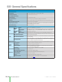
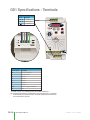
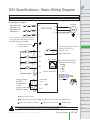
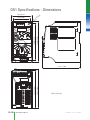
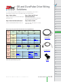
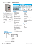
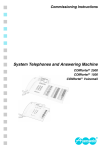
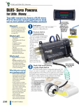
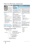
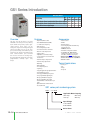
GS1 Series Introduction
GS1 Series Drives
Hp
kW
115 Volt Single-Phase Input/230 Volt Three-Phase Output
230 Volt Single-Phase Input/230 Volt Three-Phase Output
230 Volt Three-Phase Input/Output
Motor Rating
Overview
The GS1 series of AC drives is our most
affordable and compact inverter, offering
V/Hz control with general purpose application features. These drives can be
configured using the built-in digital keypad
(which also allows you to set the drive
speed, start and stop, and monitor specific
parameters) or with the standard RS-485
serial communications port. Standard
GS1 features include one analog input,
four programmable digital inputs and one
programmable normally open relay
output.
Features
.25
0.2
.5
0.4
1
0.75
✔
✔
✔
✔
✔
2
1.5
✔
Accessories
• Simple Volts/Hertz control
• Pulse Width Modulation (PWM)
• 3 - 10 kHz carrier frequency
• IGBT technology
• 130% starting torque at 5Hz
• 150% rated current for one minute
• Electronic overload protection
• Stall prevention
• Adjustable accel and decel ramps
• S-curve settings for acceleration and
deceleration
• Automatic torque compensation
• Automatic slip compensation
• DC braking
• Built-in EMI filter
• Three skip frequencies
• Trip history
• Integral keypad and speed potentiometer
• Programmable jog speed
• Three programmable preset speeds
• Four programmable digital inputs
• One programmable analog input
• One programmable relay output
• RS-485 Modbus communications up to
19.2K
• Optional Ethernet communications
• UL/cUL/CE listed
• AC line reactors
• RF filter
• Ethernet interface
• Four and eight port RS-485 multi-drop
termination board
• KEPDirect I/O Server
• GSoft drive configuration software
• GS-485HD15-CBL - ZIPLink RS485
Communication cable for connection
to the DL06 and D2-260 15-pin ports.
Detailed descriptions and specifications for the
accessories are available in the “GS/DURAPULSE
Accessories” section.
Typical Applications
• Conveyors
• Fans
• Pumps
• Shop tools
GS1 series part numbering system
GS1 - 2 0P5
Applicable Motor Capacity
0P2: 1/4hp
1P0: 1hp
0P5: 1/2hp
2P0: 2hp
Input Voltage
1: 100-120VAC
2: 200-240VAC
Series Name
12–14
Drives/Motors/Motion
1 - 80 0 - 633 - 0405
GS1 Series Specifications
PLC
Overview
DL05/06
PLC
115V/230V CLASS GS1 Series
Model
GS1-10P2
GS1-10P5
GS1-20P2
GS1-20P5
GS1-21P0
GS1-22P0
Price
<--->
<--->
<--->
<--->
<--->
<--->
Motor Rating
HP
kW
Rated Output Capacity (200V) kVA
Rated Input Voltage
Rated Output Voltage
Rated Input Current (A)
Rated Output Current (A)
Watt Loss 100% (I)
Weight: kg (lb)
Dimensions (HxWxD) mm (in)
1/4 hp
1/2 hp
1/4 hp
1/2 hp
1hp
2hp
0.2 kW
0.4 kW
0.2 kW
0.4 kW
0.7 kW
1.5 kW
0.6
1.0
0.6
1.0
1.6
2.7
Single-phase 100-120 VAC 앧10%,
50/60 Hz 앧5%
Single/three-phase: 200-240 VAC±10%, 50/60 Hz ±5%
Three-phase corresponds to double the
input voltage
Three-phase: 200240 VAC±10%,
50/60 Hz ±5%
Three-phase corresponds to the input voltage
DL205
PLC
DL305
PLC
DL405
PLC
Field I/O
6
9
4.9/1.9
6.5/2.7
9.7/5.1
9
1.6
2.5
1.6
2.5
4.2
7.0
19.2
19.2
18.4
26.8
44.6
73
2.10
2.20
2.20
2.20
2.20
2.20
Software
C-more
HMIs
Other HMI
132.0 x 68.0 x128.1 (5.20 x 2.68 x 5.04)
Accessories
Ethernet Communications module for GS Series
Drives (DIN rail mounted)
Four port RS-485 multi-drop termination board
Eight port RS-485 multi-drop termination board
Software
OPC Server
DL105
PLC
AC Drives
GS-EDRV
Motors
GS-RS485-4
GS-RS485-8
Steppers/
Servos
GSoft / KEPDirect
KEPDirect
Motor
Controls
Proximity
Sensors
Photo
Sensors
Limit
Switches
Encoders
Current
Sensors
Pushbuttons/
Lights
Process
Relays/
Timers
Comm.
TB’s &
Wiring
Power
Circuit
Protection
Enclosures
Appendix
Part Index
w w w. a u to m at i o n d i re c t . c o m / d r i ves
Drives/Motors/Motion
12–15
GS1 General Specifications
General Specifications
Control Characteristics
Control System
Rated Output Frequency
Output Frequency Resolution
Overload Capacity
Torque Characteristics
DC Braking
Acceleration/Deceleration Time
Sinusoidal Pulse Width Modulation, carrier frequency 3kHz - 10kHz
Voltage/Frequency Pattern
V/F pattern adjustable. Settings available for Constant Torque - low and high starting torque, Variable Torque low and high starting torque, and user configured
Stall Prevention Level
20 to 200% or rated current
1.0 to 400.0 Hz limited to 9999 motor rpm
0.1 Hz
150% of rated current for 1 minute
Includes auto-torque, auto-slip compensation, starting torque 130% @ 5.0Hz
Operation frequency 60-0Hz, 0-30% rated voltage. Start time 0.0-5.0 seconds. Stop time 0.0-25.0 seconds
0.1 to 600 seconds (can be set individually)
Operation Specification
Frequency
Setting
Inputs
Operation
Setting
Outputs
Keypad
Setting by <UP> or <DOWN> buttons or potentiometer
External Signal
Potentiometer - 5k액 0.5W, 0 to 10 VDC (input impedance 47k액), 0 to 20 mA / 4 to 20 mA (input impedance
250액), Multi-function inputs 1 to 3 (3 steps, JOG, UP/DOWN command), RS485 communication setting
Keypad
External Signal
Setting by <RUN>, <STOP> buttons
Multi-Function Input Signal
Multi-step selection 0 to 3, Jog, Accel/decel inhibit, First/second accel/decel switch, Counter, PLC operation,
External base block (N.C., N.O.) selection
Multi-Function Output Signal
AC drive operating, Frequency attained, Non zero speed, Base Block, Fault indication, Local/remote indication,
PLC operation indication
Operating Functions
Automatic voltage regulation, S-curve, Over-voltage stall prevention, DC braking, Fault records, Adjustable carried frequency, Starting frequency setting of DC braking, Over-current stall prevention, Momentary power loss
restart, Reverse inhibition, Frequency limits, Parameter lock/reset
Protective Functions
Operator Devices
Programming
Operator
Interface
Parameter Monitor
Environment
Key Functions
Enclosure Rating
Ambient Operating Temperature
Storage Temperature
Ambient Humidity
Vibration
Installation Location
Options
12–16
DI1, DI2, DI3, DI4 can be combined to offer various modes of operation, RS485 communication port
Drives/Motors/Motion
Overcurrent, overvoltage, undervoltage, electronic thermal motor overload, Overheating, Overload, Self testing
5-key, 4-digit, 7-segment LED, 3 status LEDs, potentiometer
Parameter values for setup and review, fault codes
Master Frequency, Output Frequency, Scaled Output Frequency, Output Voltage, DC Bus Voltage, Output
Direction, Trip Event Monitor, Trip History Monitor
RUN/STOP, DISPLAY/RESET, PROGRAM/ENTER, <UP>, <DOWN>
Protected chassis, IP20
-10° to 40°C (14°F to 104°F) w/o derating
-20° to 60 °C (-4°F to 140°F) during short-term transportation period)
0 to 90% RH (non-condensing)
9.8 m/s2(1G), less than 10Hz. 5.88 m/s2 (0.6G) 20 to 50 Hz
Altitude 1000m or lower above sea level, keep from corrosive gas, liquid and dust
Programming Software (GSOFT)
1 - 80 0 - 633 - 0405
GS1 Specifications - Installation
Company
Info.
PLCs
Understanding the installation requirements
for your GS1 drive will help to ensure that it
will operate within its environmental and electrical limits.
Field I/O
Software
NOTE:
Never use only this catalog for installation instructions or
operation of equipment; refer to the user manual, GS1-M.
C-more &
other HMI
AC Drives
Environmental Specifications
Protective Structure
Ambient Operating
Temperature 2
Storage
Temperature 3
IP20
Humidity
to 90%
(no condensation)
Vibration 4
5.9 m/S2 (0.6G),
10 to 55 Hz
Location
Altitude 1,000 m or less,
indoors (no corrosive
gases or dust)
AC Motors
Fan
Power
Transmiss.
6"
150mm
min
-10 to 40°C
-20 to 60°C
Steppers/
Servos
2"
50mm
min
Motor
Controls
Proximity
Sensors
2"
50mm
min
Limit
Switches
1: Protective structure is based upon EN60529
Encoders
2: The ambient temperature must be in the range of
-10° to 40° C. If the range will be up to 50° C, you
will need to set the carrier frequency to 2.1 kHz or
less and derate the output current to 80% or less.
See our Web site for derating curves.
Current
Sensors
6"
150mm
min
Pressure
Sensors
3: The storage temperature refers to the short-term
temperature during transport.
Temp.
Sensors
4: Conforms to the test method specified in JIS CO911
(1984)
Pushbuttons/
Lights
Panel
Watt-loss Chart
GS1 Drive Model
At full load
GS1-10P2
GS1-10P5
GS1-20P2
GS1-20P5
GS1-21P0
GS1-22P0
19.2
Ground braid
copper lugs
Input
Power
Process
To
Motor
Relays/
Timers
* FOR PAINTED SUB-PANELS,
19.2
SCRAPE THE PAINT FROM UNDER-
18.4
NEATH THE STAR WASHERS
26.8
Photo
Sensors
Star washers*
Panel or single
point ground*
BEFORE TIGHTENING THEM.
44.6
Comm.
Terminal
Blocks &
Wiring
Power
73
Air Flow
Warning: AC drives generate a large
amount of heat, which may damage the
AC drive. Auxiliary cooling methods
are typically required in order to not
exceed maximum ambient
temperatures.
Circuit
Protection
Enclosures
Tools
Appendix
Part Index
w w w. a u to m at i o n d i re c t . c o m / d r i ves
Drives/Motors/Motion
12–17
GS1 Specifications - Terminals
Main Circuit Wiring
Terminal
Description
L1, L2, L3
T1, T2, T3
Input power
AC drive output
Ground
Control Circuit Terminals
1
Terminal Symbol
Description
R1O
R1
DI1
DI2
DI3
DI4
AI 1
+10V
CM
Relay output 1 normally open
Relay output 1 common
Digital input 1
Digital input 2
Digital input 3
Digital input 4
Analog input
Internal power supply (10 mA @ 10 VDC)
Common
0 to +10 VDC, 0 to 20 mA, or 4 to 20 mA input represents zero to maximum output frequency.
Note: Use twisted-shielded, twisted-pair or shielded-lead wires for the control signal wiring. It is recommended
all signal wiring be run in a separate steel conduit. The shield wire should only be connected at the drive.
Do not connect shield wire on both ends.
12–18
Drives/Motors/Motion
1 - 80 0 - 633 - 0405
GS1 Specifications - Basic Wiring Diagram
PLC
Overview
DL05/06
PLC
Note: Users MUST connect wiring according to the circuit diagram shown below. (Refer to user manual GS1-M for additional specific wiring information.)
DL105
PLC
Note: Refer to the following pages for explanations and information regarding line reactors and RF filters: 12–50, 12–67.
DL205
PLC
Power Source 3-phase*
100-120V±10%
(50/60Hz ±5%)
200-240V±10%
(50/60Hz±5%)
AC Motor
L1
L2
GS1-xxxx
T1
IM
T2
L3
Software
* Use terminals L1 and L2 for 120V, or
select any two of the power terminals
for 240V single-phase models
C-more
HMIs
Other HMI
Grounding resistance
less than 0.1⏲
Reverse/Stop
External Fault (N.0)
DI1
R1O
Multi-function output contacts
120VAC/24VDC @5A
230VAC @2.5A
R1
Fault Indication
RJ-12 Serial Comm Port*
Interface (See Warning)
DI3
6
1
Jog
Analog voltage
0-10VDC
Potentiometer
3~5k⏲
Analog current
0-20mA; 4-20mA
Communication Port
RS-485
2: GND
3: SG4: SG+
5: +5V
Proximity
Sensors
Photo
Sensors
Limit
Switches
Encoders
*Optional ZIPLink RS485
Communication cable GS-485HD15CBL available for connection to the
DL06 and D2-260 15-pin
ports. See page 12-75.
+10V 10mA
(max)
AI
Motors
Motor
Controls
RJ-12 (6P4C)
CM
AC Drives
Steppers/
Servos
DI2
DI4
Common Signal
DL405
PLC
Field I/O
T3
Forward/Stop
DL305
PLC
Current
Sensors
Pushbuttons/
Lights
Process
Relays/
Timers
Comm.
CM
TB’s &
Wiring
Power
Factory default setting
Circuit
Protection
Factory default source of frequency command is via the keypad potentiometer
Main circuit (power) terminals
Control circuit terminal
Enclosures
Shielded leads
Appendix
WARNING: Do not plug a modem or telephone into the GS1 RJ-12 Serial Comm Port, or permanent damage may result.
Terminals 2 and 5 should not be used as a power source for your communication connection.
w w w. a u to m at i o n d i re c t . c o m / d r i ves
Drives/Motors/Motion
Part Index
12–19
GS1 Specifications - Dimensions
68.0 (2.68)
)
20
56.0 (2.20)
.
.5
dia
0.
0(
STOP
RUN
FWD
REV
0
PROG
ENTER
100
132.0 (5.20)
RUN
STOP
120.0 (4.72)
DISPL
RESET
V
I
R1 R1O+ 10V AI DI1 DI2 DI3 DI4 CM
12–20
Drives/Motors/Motion
128.1 (5.04)
123.4 (4.86)
128.1 (5.04)
Unit: mm (in)
1 - 80 0 - 633 - 0405
GS and DuraPulse Drive Wiring
Solutions
DL205
PLC
Step 3: Select the PLC and
Communication Port
Using the chart below select the drive that fits your
application needs.
DL05/06
PLC
DL105
PLC
It is easier than you think to control the GS series and DURAPULSE drives from a
DirectLOGIC or CLICK PLC when using Modbus RTU serial communications.
Step 1: Select a Drive
PLC
Overview
DL305
PLC
Select the PLC and Communication port
that works with the drive selected.
Step 2: Select the Network/Protocol
Step 4: Select a Cable
Select the Network/Protocol that the drive uses.
Select the cable (and adapter if needed)
listed in the chart.
DL405
PLC
Field I/O
Software
C-more
HMIs
Other HMI
Note: If a PLC type or PLC port is not listed in the selection charts, it does not support Modbus RTU.
Step1
Step 3
CLICK
Port 2
GS1
DuraPulse
Step1
Step 3
Not Possible
GS2
DuraPulse
Not Possible
Port 1
Port 2
Motors
Steppers/
Servos
Not Possible
GS-485HD15-CBL
GS-RJ12-CBL-2
Motor
Controls
Not Possible
GS-RJ12-CBL-2
Not Possible
FA-15HD +
GS-RJ12-CBL-2
Not Possible
Not Possible
Not Possible
GS-485HD15-CBL
Not Possible
Not Possible
Not Possible
GS-485HD15-CBL
Photo
Sensors
D4-450
Limit
Switches
D2-250-1
D2-260
Port 1
Step 2
RS485
Modbus RTU
RS232
Modbus RTU
RS485
Modbus RTU
RS485
Modbus RTU
AC Drives
DL06
Step 4
Port 2
GS1
Port 2
Step 2
RS485
Modbus RTU
RS232
Modbus RTU
RS485
Modbus RTU
RS485
Modbus RTU
GS2
DL05
Port 2
Proximity
Sensors
Port 3
Encoders
Step 4
GS-485HD15-CBL-2
Not Possible
Not Possible
GS-485HD15-CBL-2
Not Possible
FA-15HD +
GS-RJ12-CBL-2
Not Possible
FA-15HD +
GS-RJ12-CBL-2
FA-CABKIT +
GS-RJ12-CBL-2
Not Possible
Not Possible
GS-485HD15-CBL-2
Not Possible
Not Possible
Not Possible
GS-485HD15-CBL-2
Not Possible
Current
Sensors
Pushbuttons/
Lights
Process
Relays/
Timers
ZIPLinks Connector Modules specifications begin on page 26-56
ZIPLinks Cables specifications begin on page 26-74
FA-15HD
Comm.
TB’s &
Wiring
Power
Circuit
Protection
Enclosures
Appendix
Part Index
w w w. a u to m at i o n d i re c t . c o m / d r i ves
Drives/Motors/Motion
12–75