1
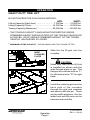
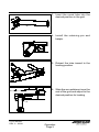
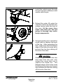
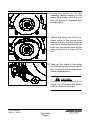
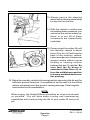
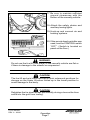
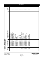
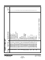
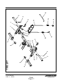
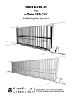
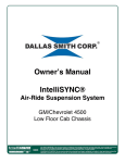
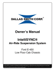
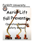
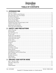
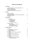
$35.00
BUS BAR GRID
USER MANUAL
1080 Hykes Road
Greencastle, PA 17225
Phone (717) 597-7111
www.jerr-dan.com
5-376-000037
REV. 6 - 03/08
© 2008 Jerr-Dan Corporation. All Rights Reserved.
OPERATION
HEAVY DUTY TIRE LIFT
DO NOT EXCEED THE FOLLOWING RATINGS:
HDTL
SHDTL
Lifting Capacity (Each Arm) .......................... 7,000 lbs. ......... 12,000 lbs.
Lifting Capacity (Total)2 ............................... 14,000 lbs. ......... 25,000 lbs.
Towing Capacity (Maximum)1 ...................... 80,000 lbs. ......... 80,000 lbs.
1
THE TOWING CAPACITY SHOULD NOT EXCEED THE GROSS
COMBINED WEIGHT RATING (GCWR) OF THE TOWING VEHICLE OR
42,000 LBS. (GCW) GROSS COMBINED WEIGHT OF THE TOWED
VEHICLE, WHICHEVER IS LOWER.
2
MAXIMUM LIFTING CAPACITY - THE MAXIMUM LOAD THAT CAN BE LIFTED.
WIDE
FLANGED
PLATE
1. Slide the tire lift grid onto the
crossbar.
CAUTION:
Make sure that the tire lift Grid
is installed as shown with the
wide flanged plate on top. The
flanges are marked with an "L"
for left hand and an "R" for right
hand.
2. Install the retaining pin from the
back side of the crossbar
through the grid and crossbar
and secure with the pin. There
are two width positions. One for
wider front end lifts and one for
narrower rear end lifts.
Operation
Page 2
5-376-000037
REV. 6 - 03/08
3. Insert the round tube into the
desired position in the grid.
4. Install the retaining pin and
hairpin.
5. Retract the tube inward to the
loading position.
6. Slide the arm weldment over the
end of the grid and adjust to the
desired position for loading.
5-376-000037
REV. 6 - 03/08
Operation
Page 3
7. Install the retaining pin through
the grid and arm weldment and
secure with the pin.
8. Extend the under lift under the
casualty vehicle so that the arm
makes contact with the front of
the tires. At the same time
make sure that you are not
going to damage any under
body components.
9. Using the pulling tool, extend the
round tube to capture the back
of the tire. After extending the
tube, make sure that the flanged
edge of the tube is turned up to
prevent the tire from sliding off
the end of the tube.
CAUTION:
When lifting a vehicle that has
dual tires from the rear, only
extend the round tube out to
capture the inside tire. The
flanged edge of the tube must
be between the tires and turned
up to prevent the tire from sliding
off the end of the tube.
Operation
Page 4
5-376-000037
REV. 6 - 03/08
10. Raise the boom to lift the
casualty vehicle slightly. At the
same time make sure that you
are not going to damage any
components.
11. Attach the hook end of the tiedown strap to the round tube
behind the tire. Pull the strap up
and cover the tire and attach the
hook on the ratchet end of the
strap to the arm in front of the
tire.
12. Take up the slack in the strap
by ratcheting the takeup spool
arm. Continue until the tires show
some compression.
CAUTION:
If vehicle to be towed is on a
slope, do not release the brake
until the load is secured.
5-376-000037
REV. 6 - 03/08
Operation
Page 5
13. Always secure the steering
wheel with a steering wheel strap
for any front or rear tow.
14. With the vehicle in neutral and
the parking brake released, you
can move the vehicle safely up,
down, in or out. All of these
movements are hydraulically
controlled.
15. Power retract the under lift until
the casualty vehicle is about
three (3) to four (4) feet from the
back of the recovery vehicle.
Leave enough room to maneuver
around corners without corner
binding or causing contact
between the two (2) vehicles. Be
sure that the fly boom is
extended at least four (4) in.
from the middle boom section
to ensure unobstructed crossbar pivoting.
16. Raise the casualty vehicle into towing position observing the far end for
sufficient ground clearance. It is possible to set the rear of a front lifted
vehicle completely onto the ground, causing damage. Take irregular
road surfaces into consideration.
NOTE:
When towing, the Underlift Boom should be as close to horizontal
as possible. You will have better turning and manuevering
capabilities and it will prolong the life of your under lift and pivot
pin.
Operation
Page 6
5-376-000037
REV. 6 - 03/08
17. Be sure to maintain sufficient
ground clearances with the
bottom of the casualty vehicle.
18. Attach the safety chains and
auxiliary towing lights.
19. Hook-up and connect air and
braking systems.
20. If the remote hand controller was
used, turn the CONTROL switch
“OFF”. (Switch is located on
panel on the floor.)
WARNING:
Do not use the tire lift if the tire(s) of the casualty vehicle are flat or
if there is damage to the wheels or suspension.
CAUTION:
The tire lift and grid tubes must be in their outermost positions for
storage on the under lift when folded up in the travel position to
avoid damage to the body.
CAUTION:
Retighten the tie-down straps periodically during a tow as the tires
settle into the grid from towing.
5-376-000037
REV. 6 - 03/08
Operation
Page 7
CAUTION:
The use of secondary tie-down chains is recommended. Fit the
secondary tie-down chains to the axle (not to any part of the
suspension or body which will rise and fall with the suspension)
arranged so as to hold the wheel down in the grid and prevent it
from jumping up, forwards, or backwards. Use load binders as
required.
CAUTION:
The use of trailer brakes or secondary braking devices while towing
is recommended.
CAUTION:
Do not tow any vehicle without safety chains being installed.
CAUTION:
Always follow the chassis manufacturer's recommended procedures
for towing. Remove drive lines and drive shafts as directed. Many
vehicles can be severely damaged unless these components are
removed prior to towing.
CAUTION:
All products are subject to age, wear and deterioation, all of which
cause a reduction in the products breaking strength capacity. It is
recommended that all products be regularly inspected. Any worn,
deformed, misused or overloaded products should be replaced
immediately.
Operation
Page 8
5-376-000037
REV. 6 - 03/08
PART NO.
3484000048
3484000049
3020000120
3020000119
3912000038
4691000274
7691000020
7691000026
7691000021
7330000278
7330000277
7759000004
3561000008
7894000028
7894000037
4561000012
ITEM
1
2
3
4
5
6
7
8
9
10
11
12
13
14
15
16
HDTL TIRE LIFT
Grid Weld RH
Grid Weld LH
Arm Weld RH
Arm Weld LH
Tube Weld
Pin
Hairpin
Hitchpin
Hitchpin
Decal - Caution
Decal - Rating
Rivet
Hook - 2"
Ratchet - 2"
Strap - 2"
Pull Hook
DESCRIPTION
1
1
1
1
2
2
2
2
2
2
2
8
4
4
2
1
QTY
PARTS
5-376-000037
REV. 6 - 03/08
Parts
Page 9
Parts
Page 10
5-376-000037
REV. 6 - 03/08
3484000073
3484000072
3020000120
3020000119
3912000033
3912000038
4691000274
7691000020
7691000026
7691000021
7330000278
7330000550
7759000004
3561000008
3561000015*
7894000028
7894000060*
7894000037
7894000057*
4561000012
1
2
3
4
5
16
15
14
6
7
8
9
10
11
12
13
PART NO.
ITEM
* included in Strap Assembly Kit, P/N 7577000368
Grid Weld RH
Grid Weld LH
Arm Weld RH
Arm Weld LH
Tube Weld - 26.75"
Tube Weld - 23"
Pin
Hairpin
Hitchpin
Hitchpin
Decal - Caution
Decal - Rating
Rivet
Hook - 2"
Hook - 3"
Ratchet - 2"
Ratchet - 3"
Strap - 2"
Strap - 3"
Pull Hook
DESCRIPTION
SHDTL TIRE LIFT
1
1
1
1
2
2
2
2
2
2
2
2
8
4
4
4
4
2
2
1
QTY
5-376-000037
REV. 6 - 03/08
Parts
Page 11
4
8
TIRE LIFT
2
7
5
6
8
10
12
11
3
9
13
14
12
11
10
1
7
13
14
15
9
6
5
16
1080 Hykes Road
Greencastle, PA 17225
Phone (717) 597-7111
www.jerr-dan.com
5-376-000037
REV. 6 - 03/08