1
Barricade™ N
Draft 11n Wireless 4-port Gigabit Broadband Router
SMCWGBR14-N
LIMITED WARRANTY
Limited Warranty Statement: SMC Networks, Inc. (“SMC”) warrants its products to be free from
defects in workmanship and materials, under normal use and service, for the applicable warranty
term. All SMC products carry a standard 90-day limited warranty from the date of purchase from
SMC or its Authorized Reseller. SMC may, at its own discretion, repair or replace any product not
operating as warranted with a similar or functionally equivalent product, during the applicable
warranty term. SMC will endeavor to repair or replace any product returned under warranty within 30
days of receipt of the product. The standard limited warranty can be upgraded to a Limited Lifetime*
warranty by registering new products within 30 days of purchase from SMC or its Authorized
Reseller. Registration can be accomplished via the enclosed product registration card or online via
the SMC website. Failure to register will not affect the standard limited warranty. The Limited
Lifetime warranty covers a product during the Life of that Product, which is defined as the period of
time during which the product is an “Active” SMC product. A product is considered to be “Active”
while it is listed on the current SMC price list. As new technologies emerge, older technologies
become obsolete and SMC will, at its discretion, replace an older product in its product line with one
that incorporates these newer technologies. At that point, the obsolete product is discontinued and is
no longer an “Active” SMC product. A list of discontinued products with their respective dates of
discontinuance can be found at: http://www.smc.com/index.cfm?action=customer_service_warranty.
All products that are replaced become the property of SMC. Replacement products may be either
new or reconditioned. Any replaced or repaired product carries either a 30-day limited warranty or
the remainder of the initial warranty, whichever is longer. SMC is not responsible for any custom
software or firmware, configuration information, or memory data of Customer contained in, stored
on, or integrated with any products returned to SMC pursuant to any warranty. Products returned to
SMC should have any customer-installed accessory or add-on components, such as expansion
modules, removed prior to returning the product for replacement. SMC is not responsible for these
items if they are returned with the product. Customers must contact SMC for a Return Material
Authorization number prior to returning any product to SMC. Proof of purchase may be required.
Any product returned to SMC without a valid Return Material Authorization (RMA) number clearly
marked on the outside of the package will be returned to customer at customer’s expense. For
warranty claims within North America, please call our toll-free customer support number at (800)
762-4968. Customers are responsible for all shipping charges from their facility to SMC. SMC is
responsible for return shipping charges from SMC to customer.
WARRANTIES EXCLUSIVE: IF AN SMC PRODUCT DOES NOT OPERATE AS WARRANTED
ABOVE, CUSTOMER’S SOLE REMEDY SHALL BE REPAIR OR REPLACEMENT OF THE
PRODUCT IN QUESTION, AT SMC’S OPTION. THE FOREGOING WARRANTIES AND
REMEDIES ARE EXCLUSIVE AND ARE IN LIEU OF ALL OTHER WARRANTIES OR
CONDITIONS, EXPRESS OR IMPLIED, EITHER IN FACT OR BY OPERATION OF LAW,
STATUTORY OR OTHERWISE, INCLUDING WARRANTIES OR CONDITIONS OF
MERCHANTABILITY AND FITNESS FOR A PARTICULAR PURPOSE. SMC NEITHER ASSUMES
NOR AUTHORIZES ANY OTHER PERSON TO ASSUME FOR IT ANY OTHER LIABILITY IN
CONNECTION WITH THE SALE, INSTALLATION, MAINTENANCE OR USE OF ITS PRODUCTS.
SMC SHALL NOT BE LIABLE UNDER THIS WARRANTY IF ITS TESTING AND EXAMINATION
DISCLOSE THE ALLEGED DEFECT IN THE PRODUCT DOES NOT EXIST OR WAS CAUSED BY
CUSTOMER’S OR ANY THIRD PERSON’S MISUSE, NEGLECT, IMPROPER INSTALLATION OR
TESTING, UNAUTHORIZED ATTEMPTS TO REPAIR, OR ANY OTHER CAUSE BEYOND THE
RANGE OF THE INTENDED USE, OR BY ACCIDENT, FIRE, LIGHTNING, OR OTHER HAZARD.
LIMITATION OF LIABILITY: IN NO EVENT, WHETHER BASED IN CONTRACT OR TORT
(INCLUDING NEGLIGENCE), SHALL SMC BE LIABLE FOR INCIDENTAL, CONSEQUENTIAL,
INDIRECT, SPECIAL, OR PUNITIVE DAMAGES OF ANY KIND, OR FOR LOSS OF REVENUE,
i
LOSS OF BUSINESS, OR OTHER FINANCIAL LOSS ARISING OUT OF OR IN CONNECTION
WITH THE SALE, INSTALLATION, MAINTENANCE, USE, PERFORMANCE, FAILURE, OR
INTERRUPTION OF ITS PRODUCTS, EVEN IF SMC OR ITS AUTHORIZED RESELLER HAS
BEEN ADVISED OF THE POSSIBILITY OF SUCH DAMAGES. SOME STATES DO NOT ALLOW
THE EXCLUSION OF IMPLIED WARRANTIES OR THE LIMITATION OF INCIDENTAL OR
CONSEQUENTIAL DAMAGES FOR CONSUMER PRODUCTS, SO THE ABOVE LIMITATIONS
AND EXCLUSIONS MAY NOT APPLY TO YOU. THIS WARRANTY GIVES YOU SPECIFIC LEGAL
RIGHTS, WHICH MAY VARY FROM STATE TO STATE. NOTHING IN THIS WARRANTY SHALL
BE TAKEN TO AFFECT YOUR STATUTORY RIGHTS.
* SMC will provide warranty service for one year following discontinuance from the active
SMC price list. Under the limited lifetime warranty, internal and external power supplies, fans,
and cables are covered by a standard one-year warranty from date of purchase.
ii
Compliances
Federal Communication Commission Interference Statement
This equipment has been tested and found to comply with the limits for a Class B digital device,
pursuant to Part 15 of the FCC Rules. These limits are designed to provide reasonable protection
against harmful interference in a residential installation. This equipment generates, uses and can
radiate radio frequency energy and, if not installed and used in accordance with the instructions,
may cause harmful interference to radio communications. However, there is no guarantee that
interference will not occur in a particular installation. If this equipment does cause harmful
interference to radio or television reception, which can be determined by turning the equipment off
and on, the user is encouraged to try to correct the interference by one or more of the following
measures:
• Reorient or relocate the receiving antenna.
• Increase the distance between the equipment and receiver.
• Connect the equipment into an outlet on a circuit different from that to which the receiver is
connected.
• Consult the dealer or an experienced radio/TV technician for help.
FCC Caution: To assure continued compliance, (example - use only shielded interface cables when
connecting to computer or peripheral devices) any changes or modifications not expressly approved
by the party responsible for compliance could void the user’s authority to operate this equipment.
This device complies with Part 15 of the FCC Rules. Operation is subject to the following two
conditions: (1) This device may not cause harmful interference, and (2) this device must accept any
interference received, including interference that may cause undesired operation.
IMPORTANT NOTE
FCC Radiation Exposure Statement:
This equipment complies with FCC radiation exposure limits set forth for an uncontrolled
environment. This transmitter must not be co-located or operating in conjunction with any other
antenna or transmitter.
iii
EC Declaration of Conformity
SMC contact for these products in Europe is:
SMC Networks Europe,
Edificio Conata II,
Calle Fructuos Gelabert 6-8, 2o, 4a,
08970 - Sant Joan Despi,
Barcelona, Spain.
Marking by the above symbol indicates compliance with the Essential Requirements of the
R&TTE Directive of the European Union (1999/5/EC). This equipment meets the following
conformance standards:
EN 300 328
EN 301 489-1
EN 301 489-17
EN 60950-1
Council recommendation 1999/519/EC of 12 July 1999, limitations of exposure of the
general public to electromagnetic fields (0 Hz to 300 GHz)
[Czech]
Společnost SMC Networks tímto prohlašuje, že toto rádiové zařízení LAN je ve shodě
se základními požadavky a dalšími příslušnými ustanoveními směrnice 1999/5/ES.
Oficiální ES prohlášení o shodě je uvedeno v příslušné části k produktu na webu
http://www.smc.com
[Danish]
SMC Networks erklærer herved, at følgende Radio LAN-enhed overholder de
væsentlige krav og andre relevante bestemmelser i direktiv 1999/5/EF. Den officielle
EU-overensstemmelseserklæring er tilgængelig under det relevante produktafsnit på
følgende webadresse: http://www.smc.com.
[German]
Hiermit erklärt SMC Networks, dass sich dieses Wireless LAN Gerät in
Übereinstimmung mit den grundlegenden Anforderungen und den anderen relevanten
Vorschriften der Richtlinie 1999/5/EG befindet. Die offizielle EC-Declaration of
Conformity finden Sie im Internet unter http://www.smc.com unter der entsprechenden
Produktkategorie.
[Estonian]
Käesolevaga kinnitab SMC Networks, et see Radio LAN seade vastab direktiivi
1995/5/EÜ põhinõuetele ja teistele asjakohastele sätetele. Ametliku EÜ
vastavusdeklaratsiooni leiate vastavast tootejaotisest aadressil http://www.smc.com.
[English]
Hereby, SMC Networks, declares that this Radio LAN device is in compliance with the
essential requirements and other relevant provisions of Directive 1999/5/EC. The
official EC-Declaration of Conformity can be found under the corresponding product
section on the web http://www.smc.com.
[Spanish]
Por medio de la presente SMC Networks declara que el Radio LAN device cumple con
iv
los requisitos esenciales y cualesquiera otras disposiciones aplicables o exigibles de la
Directiva 1999/5/CE. The official EC-Declaration of Conformity can be found under the
corresponding product section on the web http://www.smc.com
[Greek]
Με την παρούσα, η SMC Networks, δηλώνει ότι η συσκευή ασύρµατου τοπικού δικτύου
συµµορφώνεται µε τις ουσιώδεις απαιτήσεις και τις λοιπές σχετικές διατάξεις της
Οδηγίας 1999/5/EΚ. Η επίσηµη δήλωση συµµόρφωσης EΚ παρέχεται στην αντίστοιχη
ενότητα προϊόντων, στην ιστοσελίδα http://www.smc.com.
[French]
Par la présente SMC Networks déclare que l'appareil Radio LAN device est conforme
aux exigences essentielles et aux autres dispositions pertinentes de la directive
1999/5/CE. La déclaration de conformité officielle peut être trouvée sur notre site
internet http://www.smc.com dans la rubrique Produits.
[Italian]
Con la presente SMC Networks dichiara che questo Radio LAN device è conforme ai
requisiti essenziali ed alle altre disposizioni pertinenti stabilite dalla direttiva 1999/5/CE.
La Dichiarazione di conformità CE ufficiale è disponibile nella sezione dedicata al
rispettivo prodotto sul sito Web http://www.smc.com.
[Latvian]
Ar šo SMC Networks deklarē, ka Radio LAN device atbilst Direktīvas 1999/5/EK
būtiskajām prasībām un citiem ar to saistītiem noteikumiem. Oficiālā EK atbilstības
deklarācija ir atrodama attiecīgā produkta sadaļā tīmeklī http://www.smc.com.
[Lithuanian]
Šiuo „SMC Networks“ deklaruoja, kad šis radijo LAN įrenginys atitinka esminius
reikalavimus ir kitas 1999/5/EB Direktyvos nuostatas. Oficialią jo EB atitikties
deklaraciją galima rasti atitinkamų gaminių skyriuje šiame tinklalapyje:
http://www.smc.com.
[Dutch]
Hierbij verklaart SMC Networks dat het toestel Radio LAN device in overeenstemming
is met de essentiële eisen en de andere relevante bepalingen van richtlijn 1999/5/EG.
Het officiële EC- gelijkvormigheidattest kan men vinden op de internetsite
http://www.smc.com onder de betrokken productcategorie.
[Maltese]
B’dan, SMC Networks, tiddikjara li dan it-tagħmir LAN tar-Radju huwa konformi
mar-rekwiżiti essenzjali u dispożizzjonijiet rilevanti oħra ta’ Direttiva 1999/5/KE.
Id-Dikjarazzjoni ta’ Konformità uffiċjali tal-KE tinsab fit-taqsima korrispondenti fis-sit ta’
l-Internet http://www.smc.com.
[Hungarian]
Az SMC Networks kijelenti, hogy a Radio LAN eszköz megfelel a vonatkozó alapvető
követelményeknek és az 1999/5/EC irányelv egyéb előírásainak. A hivatalos EC
megfelelőségi nyilatkozat megtalálható a vonatkozó termék ismertetőjénél, a következő
címen: http://www.smc.com
[Polish]
Firma SMC Networks niniejszym oświadcza, że urządzenie Radio LAN jest zgodne z
zasadniczymi wymaganiami oraz pozostałymi stosownymi postanowieniami Dyrektywy
1999/5/EC. Oficjalna Deklaracja zgodności UE znajduje się w odpowiedniej sekcji
produktu w witrynie http://www.smc.com.
[Portuguese]
A SMC Networks declara que este dispositivo de LAN de Rádio está em conformidade
com os requisitos essenciais e com outras provisões relevantes da Directiva
v
1999/5/CE. A Declaração de Conformidade CE oficial encontra-se na secção
correspondente do produto na Web, http://www.smc.com.
[Slovenian]
Družba SMC Network izjavlja, da je naprava Radio LAN skladna z bistvenimi
zahtevami in drugimi ustreznimi predpisi direktive 1999/5/ES. Za uradno izjavo o
skladnosti ES glejte razdelek za ustrezni izdelek na spletni strani http://www.smc.com.
[Slovak]
Spoločnosť SMC Networks týmto vyhlasuje, že toto zariadenie Radio LAN spĺňa
základné požiadavky a ďalšie príslušné ustanovenia smernice 1999/5/ES. Oficiálne
prehlásenie ES o zhode je uvedené v sekcii príslušného produktu v lokalite
http://www.smc.com.
[Finnish]
SMC Networks vakuuttaa täten, että Radio LAN device -tyyppinen laite on direktiivin
1999/5/EY oleellisten vaatimusten ja sitä koskevien direktiivin muiden ehtojen
mukainen. EY:n virallinen vaatimustenmukaisuusvakuutus on tuotteen kohdalla
Web-sivustossa http://www.smc.com.
[Swedish]
Härmed intygar SMC Networks att denna Radio LAN-apparat uppfyller de väsentliga
egenskapskrav och övriga relevanta bestämmelser i direktiv 1999/5/EG. Den officiella
EG-försäkran om överensstämmelse finns under motsvarande produktavsnitt på
http://www.smc.com.
[Icelandic]
Hér með lýsir SMC Networks því yfir að þessi Radio LAN búnaður er í samræmi við
grunnkröfur og aðrar viðeigandi kröfur, sem gerðar eru í tilskipun 1999/5/EB. Opinberu
EB-samræmisyfirlýsinguna er að finna í viðeigandi hluta um þennan búnað á vefsetrinu
http://www.smc.com.
[Norwegian]
SMC Networks erklærer herved at Radio LAN-enheten er i samsvar med de
grunnleggende kravene og øvrige relevante krav i direktiv 1999/5/EF. Denne offisielle
EU-konformitetserklæringen finnes under korresponderende produktseksjon på
Internett: http://www.smc.com.
Countries of Operation & Conditions of Use in EC/ EFTA member states
[English]
This device is a 2.4 GHz wireless LAN transceiver, intended for indoor home and office
use in all notified EC and EFTA member states. In accordance with article 6.4 of the
R&TTE Directive 1999/5/EC the following EC/ EFTA member states have been notified:
Austria, Belgium, Denmark, Finland, France, Germany, Italy, Luxembourg,
Netherlands, Norway, Spain, Sweden, Switzerland, United Kingdom, Portugal, Greece,
Ireland, Iceland. Requirements for outdoor operation, like license requirements and
allowed channels of operation apply in some countries. Please contact your local
regulation authority or SMC Networks for details on current restrictions for outdoor use.
[French]
Ce produit est un appareil radio LAN transceiver de 2.4 GHz destiné aux PME et à
l’utilisation domestique dans tous les pays certifiés conformes aux conditions de l’EU et
de l’EFTA. En accord avec l’article 6.4 de la R&TTE directive 1999/5/EC, the membres
de la EU et de l’EFTA sont les suivants : Autriche, Belgique, Danemark, finalnde,
France, Allemagne, Italie, Luxembourg, Pays-Bas, Norvège, Espagne, Suède, Suisse,
vi
Royaume-Uni, Portugal, Grèce, Irelande, Icelande. Des conditions sont appliquées à
certains pays pour l’utilisation en extérieur, tels que des licences spécífiques et des
canaux d’opération. Veuillez contacter votre autorité locale ou SMC Networks pour
plus de détails quant aux restrictions actuelles concernant l’utilisation en extérieur.
[Dutch]
Dit toestel is een 2.4 Ghz draadloze Lan transceiver, bestemd voor gebruik binnen huis
en kantoor in alle geïnformeerde lidstaten van de EC en de EFTA. In overeenstemming
met artikel 6.4 van de R&T TE Directive 1999/5/EC zijn de volgende EC/EFTA lidstaten
verwittigd: België, Denemarken, Duitsland, Finland, Frankrijk,Griekenland, Ierland,
IJsland, Italië, Luxemburg, Nederland, Noorwegen,Oostenrijk, Portugal, Spanje ,
Verenigd Koninkrijk, Zweden, Zwitserland. Benodigdheden voor gebruik buiten, zoals
gebruiksvergunningen en toegelaten werkkanalen zijn van toepassing in sommige
landen. Gelieve uw lokale instantie of SMC Networks te contacteren voor details op
huidige beperkingen voor gebruik in buitenlucht.
[Spanish]
Este aparato es un transmisor inalámbrico de 2.4 GHz, previsto para el uso interior en
domicilios y Pymes en todos los Estados de la CE y la EFTA notificados. De acuerdo
con el artículo 6.4 de la Directiva R&TTE 1999/5/EC los siguientes estados de la CE y
de la EFTA han sido notificados: Austria, Bélgica, Dinamarca, Finlandia, Francia,
Alemania, Italia, Luxemburgo, Países Bajos, Noruega, España, Suecia, Suiza, Reino
Unido, Portugal, Grecia, Irlanda, Islandia. Los requisitos para su uso exterior, como
requerimiento de licencia y canales de operación permitidos se aplican en algunos
países. Por favor contacte la autoridad reguladora local o SMC Networks para más
detalles en relación con las restricciones actuales para uso exterior.
[German]
Dieses Wireless LAN Gerät arbeitet im 2.4 GHz Frequenzband und ist für den Einsatz
im Innenbereich in den benachrichtigten EC/ EFTA Mitgliedstaaten geeignet. In
Übereinstimmung mit Artikel 6.4 der R&TTE Direktive 1999/5/EC wurden folgende
Mitgliedstaaten benachrichtigt: Österreich, Belgien, Dänemark, Finland, Frankreich,
Deutschland, Italien, Luxemburg, Niederlande, Norwegen, Spanien, Schweden,
Schweiz, Großbritannien, Portugal, Griechenland, Irland, Island. Für den Einsatz im
Aussenbereich sind in einigen Ländern Lizenzen erforderlich oder die Anzahl der
Kanäle ist eingeschränkt. Bitte kontaktieren Sie Ihre Regulierungsbehörde oder SMC
Networks für die aktuellen Einschränkungen beim Einsatz im Aussenbereich.
[Czech]
Toto zařízení je přijímač a vysílač pro bezdrátové sítě LAN v pásmu 2,4 GHz, určený
pro použití v interiéru domácností a kanceláří ve všech členských zemích ES a ESVO,
kterým byl oznámen záměr uvést zařízení na trh. V souladu s čl. 6 odst. 4 směrnice
1999/5/ES o rádiových zařízeních a telekomunikačních koncových zařízeních byly
uvědoměny tyto členské země ES nebo ESVO: Belgie, Dánsko, Finsko, Francie, Irsko,
Island, Itálie, Lucembursko, Německo, Nizozemsko, Norsko, Portugalsko, Rakousko,
Řecko, Spojené království, Španělsko, Švédsko, Švýcarsko. Na použití ve venkovním
prostředí se v některých zemích vztahují určité požadavky, např. požadavky na licenci
nebo provoz v povolených kanálech. O omezení venkovního použití se informujte u
místních regulátorů nebo u společnosti SMC Networks.
[Danish]
Enheden er en 2,4 GHz trådløs LAN-transceiver, beregnet til indendørs hjemme- og
vii
kontorbrug i alle notificerede EU- og EFTA-medlemslande. I henhold til afsnit 6.4 i
R&TTE-direktivet 1999/5/EF er følgende EU-/EFTA-medlemslande notificeret: Østrig,
Belgien, Danmark, Finland, Frankrig, Tyskland, Grækenland, Island, Irland, Italien,
Luxembourg, Holland, Norge, Portugal, Spanien, Sverige, Schweiz og Storbritannien. I
visse lande gælder der krav vedrørende udendørs betjening af enheden, f.eks.
licenskrav og tilladte betjeningskanaler. Kontakt de lokale lovgivende myndigheder eller
SMC Networks for at få oplysninger om aktuelle begrænsninger vedrørende udendørs
betjening.
[Estonian]
See seade on 2.4 GHz juhtmeta LAN vastuvõtu-saatejaam, mis on mõeldud kodus ja
kontoris kasutamiseks kõikides teavitatud EÜ ja Euroopa Vabakaubanduse
Assotsiatsiooni (EFTA) liikmesriikides. Vastavalt R&TTE direktiivi 1999/5/EÜ
paragrahvile 6.4 on teavitatud järgmisi EÜ/EFTA liikmesriike: Austriat, Belgiat, Taanit,
Soomet, Prantsusmaad, Saksamaad, Itaaliat, Luksemburgi, Hollandit, Norrat,
Hispaaniat, Rootsit, Šveitsi, Ühendkuningriiki, Portugali, Kreekat, Iirimaad, Islandi.
Mõningates riikides kehtivad väljas kasutamiseks nõuded, näiteks litsentsinõuded ja
lubatud töökanalid. Palun teavitage vastavat kohalikku ametkonda või ettevõtet SMC
Networks’i, kui soovite täpsemaid andmeid väljas kasutamisel kehtivate piirangute
kohta.
[Greek]
Αυτή η συσκευή είναι ένας ασύρµατος ποµποδέκτης τοπικού δικτύου 2,4 GHz, που
προορίζεται για οικιακή και επαγγελµατική χρήση σε εσωτερικό χώρο, σε όλα τα
κράτη-µέλη της ΕΚ και της ΕΖΕΣ. Σύµφωνα µε το άρθρο 6.4 της Οδηγίας για
ραδιοεξοπλισµό και τηλεπικοινωνιακό τερµατικό εξοπλισµό (R&TTE), 1999/5/ΕΚ, έχουν
ανακοινωθεί τα ακόλουθα κράτη-µέλη ΕΕ/ΕΖΕΣ: Αυστρία, Βέλγιο, ∆ανία, Φιλανδία,
Γαλλία, Γερµανία, Ιταλία, Λουξεµβούργο, Ολλανδία, Νορβηγία, Ισπανία, Σουηδία,
Ελβετία, Ηνωµένο Βασίλειο, Πορτογαλία, Ελλάδα, Ιρλανδία, Ισλανδία. Σε ορισµένες
χώρες επιβάλλονται απαιτήσεις για χρήση σε εξωτερικό χώρο, όπως απαιτήσεις
παραχώρησης άδειας και επιτρεπόµενα κανάλια λειτουργίας. Απευθυνθείτε στην
τοπική αρµόδια αρχή ή στην SMC Networks για λεπτοµέρειες σχετικά µε τους
τρέχοντες περιορισµούς για χρήση σε εξωτερικό χώρο.
[Italian]
Il presente device è un ricetrasmettitore LAN wireless da 2,4 GHz, previsto per l'uso in
interni a casa e in ufficio in tutti gli Stati membri della CE e dell'EFTA notificati.
Conformemente all'articolo 6.4 della Direttiva 1999/5/CE R&TTE, sono stati notificati i
seguenti Stati membri della CE/dell'EFTA: Austria, Belgio, Danimarca, Finlandia,
Francia, Germania, Grecia, Irlanda, Islanda, Italia, Lussemburgo, Norvegia, Paesi
Bassi, Portogallo, Regno Unito, Spagna, Svezia, Svizzera. In alcuni Paesi si applicano
i requisiti per il funzionamento in esterni, quali requisiti di licenza e canali consentiti.
Contattare l'Autorità normativa locale del proprio Paese o SMC Networks per
informazioni dettagliate sulle limitazioni correnti per l'utilizzo in esterni.
[Latvian]
Šī ierīce ir 2,4 GHz bezvadu LAN raiduztvērējs, kas paredzēts izmantošanai iekštelpās
mājās un birojos visās paziņotajās EK un EBTA (European Free Trade Association Eiropas brīvās tirdzniecības asociācija) dalībvalstīs. Atbilstoši radioiekārtu un
telekomunikāciju gala iekārtu direktīvas 1999/5/EK 6.4. pantam paziņotās EK/EBTA
valstis ir : Austrija, Beļģija, Dānija, Somija, Francija, Vācija, Itālija, Luksemburga,
Nīderlande, Norvēģija, Spānija, Zviedrija, Šveice, Apvienotā Karaliste, Portugāle,
Grieķija, Īrija, Islande. Dažās valstīs ir spēkā ierobežojumi lietošanai ārvidē, piemēram,
licences prasības un darbībai atļautie kanāli. Lūdzu, sazinieties ar vietējo regulējošo
viii
instanci vai SMC Network, lai saņemtu informāciju par pašreizējiem ierobežojumiem
lietošanai ārvidē.
[Lithuanian]
Šis įrenginys yra 2,4 GHz belaidis LAN siųstuvas-imtuvas, skirtas naudoti patalpose
namie ar biure visose notifikuotose EB ir ELPA šalyse narėse. Pagal RTTE Direktyvos
1999/5/EB 6.4 straipsnį, notifikuotos yra šios EB/ELPA šalys narės: Austrija, Belgija,
Danija, Suomija, Prancūzija, Vokietija, Italija, Liuksemburgas, Nyderlandai, Norvegija,
Ispanija, Švedija, Šveicarija, Jungtinė Karalystė, Portugalija, Graikija, Airija, Islandija.
Kai kuriose šalyse galioja tam tikri reikalavimai norint naudoti įrenginį lauke, pvz.,
licencijos ir suteikti ryšio kanalai. Jei norite sužinoti, kokie apribojimai galioja norint
naudoti įrenginį lauke, kreipkitės į nacionalinę reguliavimo instituciją arba „SMC
Networks“.
[Maltese]
Dan it-tagħmir huwa LAN transreciever mingħajr fili ta’ 2.4 GHz maħsub biex jintuża fuq
ġewwa fi djar u uffiċċini fil-pajjiżi notifikati tal-KE u
l-Istati Membri ta’ l-EFTA. B’mod konformi ma’ Artikolu 6.4 tad-Direttiva R&TTE
1999/5/KE l-Istati Membri tal-KE/EFTA li ġejjin ġew notifikati: L-Awstrija, Il-Belġju,
Id-Danimarka, Il-Finlandja, Franza, Il-Ġermanja, L-Italja, Il-Lussemburgu, L-Olanda,
In-Norveġja, Spanja, L-Iżveżja, L-Iżvizzera, Ir-Renju Unit, Il-Portugal, Il-Greċja,
L-Irlanda, L-Islanda. Rekwiżiti għal tħaddim fuq barra, bħal ħtiġijiet ta’ liċenzja u kanali
permessi għal tħaddim japplikaw f’ċertu pajjiżi. Jekk jogħġbok ikkuntattja lill-awtorità
regolarorja lokali jew SMC Networks għal dettalji dwar restrizzjonijiet attwali dwar l-użu
fuq barra.
[Hungarian]
Ez az eszköz egy 2,4 GHz-es vezeték nélküli LAN adó-vevő, amely beltéri és irodai
használatra készült, és az összes értesített EC- és EFTA-tagországban használható.
Az 1999/5/EC jelű R&TTE előírás 6.4-es cikkének megfelelően a következő EC/
EFTA tagországok kaptak értesítést: Ausztria, Belgium, Dánia, Finnország,
Franciaország, Németország, Olaszország, Luxemburg, Hollandia, Norvégia,
Spanyolország, Svédország, Svájc, Egyesült Királyság, Portugália, Görögország,
Írország és Izland. Egyes országokban külön előírások vonatkoznak a kültéri
használatra, például a licencre és az engedélyezett csatornákra. A kültéri használatra
vonatkozó aktuális előírásokkal kapcsolatos részletekért forduljon a helyi szabályozó
hatósághoz vagy az SMC Networkshöz.
[Polish]
Niniejsze urządzenie to urządzenie do odbierania i przesyłania sygnału (transceiver) w
bezprzewodowej sieci LAN o częstotliwości 2,4 GHz, przeznaczone do użytku
wewnątrz pomieszczeń, w domach i biurach we wszystkich krajach członkowskich UE i
EFTA. Zgodnie z artykułem 6.4 dyrektywy 1999/5/EC dotyczącej norm dla urządzeń
radiowych i końcowych urządzeń teletransmisyjnych powiadomione zostały
następujące kraje członkowskie: Austria, Belgia, Dania, Finlandia, Francja, Niemcy,
Włochy, Luksemburg, Holandia, Hiszpania, Szwecja, Szwajcaria, Wielka Brytania,
Portugalia, Grecja, Irlandia, Islandia. W niektórych krajach obowiązują wymagania
dotyczące działania na zewnątrz budynków, na przykład wymagania licencyjne i
dozwolone kanały pracy. Szczegółowe informacje na temat obowiązujących
ograniczeń użytkowania zewnętrznego można uzyskać, kontaktując się z lokalnym
urzędem regulacji lub firmą SMC Networks.
[Portuguese]
Este dispositivo é um transreceptor de LAN sem fios de 2,4 GHz, destinado a uma
utilização interior em casa e no escritório, em todos os Estados membros notificados
ix
da CE e da EFTA. De acordo com o artigo 6.4 da Directiva sobre R&TTE 1999/5/CE,
foram notificados os seguintes Estados membros da CE/EFTA: Áustria, Bélgica,
Dinamarca, Finlândia, França, Alemanha, Itália, Luxemburgo, Holanda, Noruega,
Espanha, Suécia, Suíça, Reino Unido, Portugal, Grécia, Irlanda, Islândia. Os requisitos
para uma utilização no exterior, tais como de licença e de canais de funcionamento
permitidos aplicam-se a alguns países. Para obter informações sobre as restrições de
utilização no exterior, contacte a autoridade local competente ou a SMC Networks.
[Slovenian]
Ta naprava je oddajno-sprejemna enota za brezžično lokalno omrežje, namenjena
uporabi na domu ali v pisarni v vseh priglašenih državah članicah ES in EFTA. Skladno
s členom 6.4 Direktive 1999/5/ES o radijski opremi in telekomunikacijski terminalski
opremi so bile obveščene naslednje države članice ES/EFTA: Avstrija, Belgija, Danska,
Finska, Francija, Nemčija, Italija, Luksemburg, Nizozemska, Norveška, Španija,
Švedska, Švica, Velika Britanija, Portugalska, Grčija, Irska, Islandija. V nekaterih
državah veljajo zahteve za delovanje na prostem, kot so zahteve za dovoljenje in
dovoljeni kanali za delovanje. Če potrebujete natančne informacije o trenutnih
omejitvah uporabe na prostem, se obrnite na lokalni regulativni organ ali družbo SMC
Networks.
[Slovak]
Toto zariadenie je prijímač a vysielač pre bezdrôtové siete v pásme 2,4 GHz a je
určené na použitie v interiéroch domácností a kancelárií vo všetkých členských štátoch
ES a EZVO, ktorým bol oznámený zámer uviesť zariadenie na trh. V súlade s čl. 6
odst. 4 smernice 1999/5/ES o rádiovom zariadení a koncových telekomunikačných
zariadeniach boli upovedomené nasledujúce členské štáty ES/EZVO: Belgicko,
Dánsko, Francúzsko, Fínsko, Grécko, Holandsko, Island, Írsko, Luxembursko,
Nemecko, Nórsko, Portugalsko, Rakúsko, Španielsko, Švajčiarsko, Švédsko,
Taliansko, Veľká Británia. V niektorých štátoch sa na prevádzku v exteriéroch vzťahujú
určité požiadavky, napríklad požiadavky na licenciu alebo požiadavky na prevádzkové
kanály. Podrobné informácie o aktuálnych obmedzeniach pri prevádzke v exteriéroch
vám poskytnú miestne regulačné orgány alebo spoločnosť SMC Networks.
[Finnish]
Laite on 2,4 GHz:n langaton LAN-vastaanotin, joka on tarkoitettu koti- ja
toimistokäyttöön kaikissa EY:n ja EFTAn jäsenmaissa, joihin siitä on ilmoitettu. Radioja telepäätelaitedirektiivin 1999/5/EY mukaisesti seuraaville EY-/EFTA-maille on
ilmoitettu: Itävalta, Belgia, Tanska, Suomi, Ranska, Saksa, Italia, Luxemburg,
Alankomaat, Norja, Espanja, Ruotsi, Sveitsi, Iso-Britannia, Portugali, Kreikka, Irlanti ja
Islanti. Joissakin maissa ulkokäyttöä koskevat erilliset vaatimukset, kuten erikseen
anottava lupa ja sallittujen kanavien rajoittaminen. Ota yhteyttä paikalliseen käyttöä
valvovaan viranomaiseen tai SMC Networksiin, jos haluat lisätietoja laitteen ulkokäytön
rajoituksista.
[Swedish]
Apparaten är en 2,4 GHz trådlös LAN-mottagare för inomhusbruk i hem och på kontor i
alla underrättade EG- och EFTA-medlemsstater. Enligt artikel 6.4 i R&TTE-direktivet
1999/5/EG är följande EG-/EFTA-stater underrättade: Österrike, Belgien, Danmark,
Finland, Frankrike, Tyskland, Italien, Luxemburg, Nederländerna, Norge, Spanien,
Sverige, Schweiz, Storbritannien, Portugal, Grekland, Irland och Island. I vissa länder
tillkommer krav för utomhusbruk, t.ex. licenskrav och tillåtna användarkanaler.
Kontakta lokala tillsynsmyndigheter eller SMC Networks för information om aktuella
bestämmelser för utomhusbruk.
x
[Icelandic]
Þessi búnaður er 2,4 GHz þráðlaust LAN sendiviðtæki til notkunar innanhúss á heimili
og skrifstofu í öllum tilkynntum aðildarríkjum EB og EFTA. Í samræmi við grein 6.4 í
R&TTE tilskipuninni 1999/5/EB hefur eftirfarandi aðildarríkjum EB/EFTA verið tilkynnt
þar um: Austurríki, Belgía, Danmörk, Finnland, Frakkland, Þýskaland, Ítalía,
Lúxemborg, Holland, Noregur, Spánn, Svíþjóð, Sviss, Bretland, Portúgal, Grikkland,
Írland, Ísland. Kröfur fyrir notkun utanhúss, svo sem kröfur um leyfi og heimilaðar rásir
eiga við í sumum löndum. Hafið samband við reglugerðaryfirvöld á hverjum stað eða
SMC Networks til að fá upplýsingar um gildandi takmarkanir á notkun utanhúss.
[Norwegian]
Denne enheten er en trådløs 2.4 GHz LAN-mottaker som er beregnet for innendørs
privat- og kontorbruk i alle underrettede EF- og EFTA-medlemsstater. I
overensstemmelse med artikkel 6.4 i R&TTE-direktivet 1999/5/EF, har følgende EF-/
EFTA-medlemsstater blitt underrettet: Østerrike, Belgia, Danmark, Finland, Frankrike,
Tyskland, Italia, Luxembourg, Nederland, Norge, Spania, Sverige, Sveits, Storbritannia,
Portugal, Hellas, Irland og Island. Krav for utendørsbruk, som lisenskrav og tillatte
brukskanaler, gjelder i noen land. Ta kontakt med din lokale regulerende myndighet
eller SMC Networks for detaljert informasjon om gjeldende begrensninger for utendørs
bruk.
Requirements for indoor vs. outdoor operation, license requirements and allowed channels
of operation apply in some countries as described below:
. In Italy the end-user must apply for a license from the national spectrum authority to operate this
device outdoors.
. In Belgium outdoor operation is only permitted using the 2.46 - 2.4835 GHz band:
Channel 13.
. In France outdoor operation is only permitted using the 2.4 - 2.454 GHz band: Channels
1 - 7.
Italian:
In alcuni Paesi si applicano i requisiti per il funzionamento in interni-esterni, i requisiti di licenza e i
canali consentiti, come descritto si seguito:
- In Italia l'utente finale deve richiedere una licenza all'Autorità competente nazionale per il
funzionamento in esterni del device.
Dutch:
Vereisten voor werking indoor versus outdoor, licentie vereisten en toegestane kanalen voor
gebruik zijn van toepassing in bepaalde landen zoals hieronder beschreven.
- In Belgïe is outdoor gebruik enkel toegestaan gebruik makend van de 2.46 - 2.4835 GHz band:
Kanaal13.
French:
Conditions requises pour des installations intérieures ou extérieures, licences requises et
canaux autorisés dans certains pays comme décrits ci-dessous:
- En Belgique, l'installation extérieure est seulement autorisée sur la bande 2.46 - 2.4835 GHz::
Canal 13
- En France, l'installation extérieure est seulement autorisée sur la bande 2.4 - 2.454 GHz :
Canal 1-7
xi
Table of Contents
Getting Started with the SMCWGBR14-N
Package Contents
Minimum System Requirements
3
4
4
Wireless LAN Networking
5
Introduction
Features
9
9
Hardware Overview
Back Panel
Front Panel
Installation Considerations
Getting Started
11
11
12
14
14
Using the Configuration Menu
Basic
Advanced
Tools
Status
15
16
27
67
86
Using the USB2.0 Multi-function Print Server
Introduction
System Setup
Printer Wizard
Scanning Webpage
100
100
100
101
105
Appendix A: Printer compatibility list
109
Glossary
111
2
Getting Started with the
SMCWGBR14-N
Congratulations on purchasing the SMCWGBR14-N. This manual provides information for setting
up and configuring the SMCWGBR14-N. This manual is intended for both home users and
professionals.
The following
conventions are used
in this manual:
THE NOTE SYMBOL INDICATES ADDITIONAL INFORMATION ON THE
TOPIC AT HAND.
THE TIP SYMBOL INDICATES HELPFULL INFORMATION AND TIPS TO
IMPROVE YOUR NETWORK EXPERIENCE.
THE CAUTION SYMBOL ALERTS YOU TO SITUATIONS THAT MAY
DEGRADE YOUR NETWORKING EXPERIENCE OR COMPROMISE
LIKE NOTES AND TIPS, THE IMPORTANT SYMBOL INDICATES
INFORMATION THAT CAN IMPROVE NETWORKING. THIS INFORMATION
SHOULD NOT BE OVERLOOKED.
3
Package Contents
Barricade™ N Broadband Router (SMCWGBR14-N)
Yellow RJ-45 Ethernet Cable
Power Adapter (12V, 1A)
Documentation CD
Quick Installation Guide
Warranty Information Card
Using a power supply with a different voltage than the one included with your
product will cause damage and void the warranty for this product.
Minimum System Requirements
Broadband (Cable/xDSL) Internet service and Modem with Ethernet connection.
2.4GHz 802.11n draft wireless adapter or 2.4GHz 802.11b/g wireless adapter installed on
each PC. Alternatively an Ethernet adapter can be used.
Internet Explorer 5.5 or above, Netscape 4.7 or above, Mozilla Firefox 1.0 or above
4
Wireless LAN Networking
This section provides background information on wireless LAN networking technology. Consult
the Glossary for definitions of the terminology used in this section.
THE INFORMATION IN THIS SECTION IS FOR YOUR REFERENCE. CHANGING
NETWORK SETTINGS AND PARTICULARLY SECURITY SETTTINGS SHOULD ONLY
BE DONE BY AN AUTHORIZED ADMINISTRATOR.
Transmission Rate (Transfer Rate)
The SMCWGBR14-N provides various transmission (data) rate options for you to select. In most
networking scenarios, the factory default Best (automatic) setting proves the most efficient. This
setting allows your SMCWGBR14-N to operate at the maximum transmission (data) rate. When
the communication quality drops below a certain level, the SMCWGBR14-N automatically
switches to a lower transmission (data) rate. Transmission at lower data speeds is usually more
reliable. However, when the communication quality improves again, the SMCWGBR14-N gradually
increases the transmission (data) rate again until it reaches the highest available transmission
rate.
Types of Wireless Networks
Wireless LAN networking works in either of the two modes: ad-hoc and infrastructure. In infrastructure mode, wireless devices communicate to a wired LAN via access points. Each access
point and its wireless devices are known as a Basic Service Set (BSS). An Extended Service Set
(ESS) is two or more BSSs in the same subnet. In ad hoc mode (also known as peer-to-peer
mode), wireless devices communicate with each other directly and do not use an access point.
This is an Independent BSS (IBSS).
To connect to a wired network within a coverage area using access points, set the operation mode
to Infrastructure (BSS). To set up an independent wireless workgroup without an access point, use
Ad-hoc (IBSS) mode.
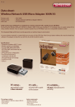
A D -H OC (IBSS) N ETWORK
Ad-hoc mode does not require an access point or a wired network. Two or more wireless stations
communicate directly to each other. An ad-hoc network may sometimes be referred to as an
Independent Basic Service Set (IBSS).
To set up an ad-hoc network, configure all the stations in ad-hoc mode. Use the same SSID and
5
channel for each station.
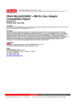
6
When a number of wireless stations are connected using a single access point, you have a Basic
Service Set (BSS).
In the ESS diagram below, communication is done through the access points, which relay data
packets to other wireless stations or devices connected to the wired network. Wireless stations
can then access resources, such as a printer, on the wired network.
7
In an ESS environment, users are able to move from one access point to another without losing the
connection. In the diagram below, when the user moves from BSS (1) to BSS (2) the WLAN client
devices automatically switches to the channel used in BSS (2).
Roaming in an ESS network diagram
8
Introduction
The Barricade™ N Draft 11n Gigabit Broadband Router (SMCWGBR14-N) is the perfect all-in-one
networking solution for connecting and sharing your high speed cable/xDSL internet connection.
Designed for the home and office, this platform independent multi-functional router combines a 4-port
10/100/1000 LAN switch, high speed Wireless-N (draft 802.11n) access point, NAT firewall with
Stateful Packet Inspection (SPI), Intelligent stream handling technology, a Multi-function print server
and a User friendly web-based management interface in one convenient device.
The built-in wireless access point is 802.11n draft v2.0 compliant while maintaining full backwards
compatibility with the Wireless-G (802.11g) and Wireless-B (802.11b) standards. This next generation
wireless networking standard utilizes advanced MIMO (Multiple-In, Multiple-Out) technology to deliver
incredible speed and range. With wireless speeds up to 300Mbps and extended coverage, there is
enough bandwidth to simultaneously stream video and audio, play online games, transfer large files,
make VoIP calls and surf the Internet. With security being a key consideration, SMCWGBR14-N
supports the latest WPA and WPA2 wireless encryption standards, which prevent unauthorized
access to wireless networks and ensure data is secure. Wireless security can also be set up easily
using Wi-Fi Protected SetupTM (WPS) that enables push button or PIN configuration. The 4-port
10/100/1000 LAN switch is ideal for connecting Gigabit Ethernet devices, such as Network Attached
Storage (NAS), and transferring large files or streaming media content at up to gigabit speeds.
The integrated NAT firewall with SPI provides protection from hackers and Denial of Service attacks
by analyzing individual data packets, to ensure that only authorized packets are allowed access to the
network. Using the Access Control feature parents or network administrators can block certain
websites, limit web access based on time or dates, and/or block internet access for applications like
P2P utilities or games. Intelligent stream handling technology automatically manages and prioritizes
the flow of time-sensitive data in your local network and going to the Internet, without the need for end
user configuration. As a result time-sensitive applications like online gaming and video, run smoothly
without lag and breakup problems. We’ve also included a USB2.0 multi-function print server which
supports both printing and scanning*. The print server has been designed with ease-of-use at the
forefront and can be setup in minutes using the printer installation wizard. Scanning and saving of
documents is performed using a web-based interface so there is no need to install scanning software
on each computer. Finally, configuration of your internet connection and advanced router functions is
made simple and straightforward with the EZ™ Installation Wizard and intuitive web-based
management interface.
Features
Wi-Fi Compliant with IEEE 802.11n (draft) and IEEEE 802.11b/g Standards
2.412 to 2.462GHz frequency band operation
Compliant with IEEE 802.3 & 3u standards
Support OFDM and CCK modulation
High-Speed up to 300Mbps Data Rate using IEEE 802.11n (draft) connection
Supports Cable/DSL Modems with Dynamic IP, Static IP, PPPoE, PPTP, L2TP or BigPond
Connection Types
Firewall features Network Address Translation (NAT), and Stateful Packet Inspection (SPI)
9
protects against Dos attacks
Traffic Control with Virtual Server (max 64 configurable servers) and DMZ
UPnP (Universal Plug & Play) and ALGs Support for Internet applications such as Email, FTP,
Gaming, Remote Desktop, Net Meeting, Telnet, and more
Provides Additional Security of Enable/Disable SSID, Internet Access Control (Services, URL and
MAC Filtering)
Supports Multiple and Concurrent IPSec, L2TP and PPTP VPN Pass-Through Sessions
Flash Memory for Firmware Upgrade, Save/Restore Settings
Easy Management via Web Browser (HTTP) and Remote Management
Supports 64/128-bit WEP, WPA/WPA2, and WPA-PSK/WPA2-PSK
Compliant with Windows 98/NT/2000/XP/2003 Server, Linux and Mac OS
Support 4 x 10/100/1000Mbps Auto-MDIX LAN Port and 1 x 10/100/1000Mbps WAN Port
(Internet)
Built-in 3 External Antennas to support high speed performance and great coverage
USB2.0 Multi-function print server
10
Hardware Overview
Back Panel
POWER
The Power input connector is a single jack socket to supply power to the SMCWGBR14-N.
Please use the Power Adapter provided in the SMCWGBR14-N package.
RESET
Pressing the reset button for 10 seconds restores the router to its original factory default settings.
WAN (Auto MDI/MDIX)
The WAN port is used to connect to an Ethernet Cable or xDSL modem
LAN1-4 (Auto MDI/MDIX)
The LAN ports are used for connecting networking devices such as PC’s, Printers & Switches. The
LAN ports automatically sense the cable type when connecting to Ethernet enabled computers.
11
Front Panel
POWER LED
A solid green LED indicates the SMCWGBR14-N is receiving power – normal operation. If the LED is
off there is no power to device or failure.
LAN1-4 LED
A solid orange LED indicates the corresponding LAN port connection is established. The LED blinks
when data is transmitted. If the LED is off there is no link for corresponding LAN port.
WAN LED
A solid orange LED indicates the WAN port connection is established. The LED blinks when
data is transmitted. If the LED is off there is no link for the WAN port.
WLAN LED
A solid orange LED indicates the wireless AP is ready. The LED blinks when wireless data is
transmitted.
WPS LED
After pressing the WPS button for 4 seconds the WPS LED will blink continually. When a
client joins the network successfully the LED will stop blinking and become solid until the next
WPS action or the device is rebooted. If no client joins the LED will stop blinking and switch
off after 4 minutes.
WPS Button
Press and hold the WPS button for 4 seconds to automatically configure wireless security. If the client
device supports WPS Push Button Configuration (PBC) you will need to press the button within 60
seconds to automatically configure security on the client. Note: WPS LED will start to flash after
pressing WPS button for 4 seconds. When a client joins the network successfully the LED will stop
12
blinking and become solid until the next WPS action or the device is rebooted. If no client joins the
LED will stop blinking and switch off after 4 minutes.
USB
The USB2.0 port can be used for connecting USB printers. For a list of printers refer to Appendix A.
WLAN ON/OFF
The WLAN ON/OFF slide switch can be used to turn the wireless AP function ON/OFF
13
Installation Considerations
The SMCWGBR14-N lets you access your network, using a wireless connection, from virtually
anywhere within its operating range. Keep in mind, however, that the number, thickness and location
of walls, ceilings, or other objects that the wireless signals must pass through, may limit the range.
Typical ranges vary depending on the types of materials and background RF (radio frequency) noise
in your home or business. The key to maximizing wireless range is to follow these basic guidelines:
1
Keep the number of walls and ceilings between the SMCWGBR14-N and other network
devices to a minimum - each wall or ceiling can reduce your wireless product’s range from
3-90 feet (1-30 meters.) Position your devices so that the number of walls or ceilings is
minimized.
2
Be aware of the direct line between network devices. A wall that is 1.5 feet thick (.5 meters), at
a 45-degree angle appears to be almost 3 feet (1 meter) thick. At a 2-degree angle it looks
over 42 feet (14 meters) thick! Position devices so that the signal will travel straight through a
wall or ceiling (instead of at an angle) for better reception.
3
Building Materials can impede the wireless signal - a solid metal door or aluminum studs may
have a negative effect on range. Try to position wireless devices and computers with wireless
adapters so that the signal passes through drywall or open doorways and not other materials.
4
Keep your product away (at least 3-6 feet or 1-2 meters) from electrical devices or appliances
that generate extreme RF noise.
Getting Started
For a typical home setup, you will need a Broadband (Cable/xDSL) Internet service and Modem
with Ethernet connection. Consult with your Cable or xDSL provider for proper installation of the
modem. Please do the following:
1. Connect your Broadband modem (Cable/xDSL) to the blue WAN port on the Barricade™
2. Connect the network card of your PC to the yellow LAN port on the Barricade™ using the
yellow RJ-45 cable provided. Now connect the power adapter.
3. Reboot PC. Start web browser and enter address http://192.168.2.1. When prompted enter
password smcadmin then click [Log In]. Note: The User Name must be set to Admin.
4. Click [BASIC], then [Setup Wizard], then [Launch Internet Connection Setup Wizard]. Follow
the on screen instructions to complete the set-up and reboot the Barricade™. You are now
ready to enjoy your Internet connection.
14
Using the Configuration Menu
Whenever you want to configure your SMCWGBR14-N, you can access the Configuration Menu
through your PC by opening the Web-browser and typing in the IP Address of the SMCWGBR14-N.
The SMCWGBR14-N default IP address is: http://192.168.2.1
Open the Web browser.
Type in the IP Address of the Router (http://192.168.2.1).
If you have changed the default IP Address assigned to the SMCWGBR14-N, make sure
you enter the correct IP Address.
Select Admin in the User Name field.
Enter Password: smcadmin (default).
Click Log In.
If you have changed the default password assigned to the SMCWGBR14-N, make sure you
enter the correct password.
15
Basic
The Basic tab provides the following configuration options: INTERNET, WIRELESS and NETWORK
SETTINGS.
Basic_Internet
Setup Wizard
If you are new to networking and have never configured a router before, click on Setup Wizard
and the router will guide you through a few simple steps to get your network up and running.
Manual Configure
If you consider yourself an advanced user and have configured a router before, click Manual
Configure to input all the settings manually.
16
Basic_Wireless
The wireless section is used to configure the wireless settings for your router. Note that changes made
in this section may also need to be duplicated on wireless clients that you want to connect to your
wireless network.
To protect your privacy, use the wireless security mode to configure the wireless security
features. This device supports three wireless security modes including: WEP, WPA-Personal,
and WPA-Enterprise. WEP is the original wireless encryption standard. WPA-Enterprise
provides a higher level of security. WPA-Personal does not require an authentication server.
The WPA-Enterprise option requires a RADIUS authentication server.
17
Enable Wireless
This option allows you to enable/disable the wireless AP function. The wireless can also be
turned ON/OFF by the slide switch on the back panel. When the wireless is enabled, the
following parameters are in effect.
Wireless Network Name
When you are browsing for available wireless networks, this is the name that will appear in the
list (unless Visibility Status is set to Invisible, see below). This name is also referred to as the
SSID. For security purposes, it is highly recommended to change from the pre-configured
network name.
Enable Auto Channel Scan
If you select this option, the router automatically finds the channel with least interference and
uses that channel for wireless networking. If you disable this option, the router uses the
channel that you specify with the following Wireless Channel option.
Wireless Channel
A wireless network uses specific channels in the wireless spectrum to handle communication
between clients. Some channels in your area may have interference from other electronic
devices. Choose the clearest channel to help optimize the performance and coverage of your
wireless network.
802.11 Mode
If all of the wireless devices you want to connect with this router can connect in the same
transmission mode, you can improve performance slightly by choosing the appropriate "Only"
mode. If you have some devices that use a different transmission mode, choose the
appropriate "Mixed" mode.
Channel Width
The "Auto 20/40 MHz" option is usually best. The other options are available for special
circumstances. Note that when 20/40MHz option is selected, an extended channel will be used
to extend the data rate.
Transmission Rate
By default the fastest possible transmission rate will be selected. You have the option of
selecting the speed if necessary.
Visibility Status
The Invisible option allows you to hide your wireless network. When this option is set to Visible,
your wireless network name is broadcast to anyone within the range of your signal. If you're not
using encryption then they could connect to your network. When Invisible mode is enabled,
you must enter the Wireless Network Name (SSID) on the client manually to connect to the
network.
Security Mode (NONE, WEP, WPA-Personal, WPA-Enterprise)
Unless one of these encryption modes is selected, wireless transmissions to and from your
wireless network can be easily intercepted and interpreted by unauthorized users.
18
WEP
A method of encrypting data for wireless communication intended to provide the same level of
privacy as a wired network. WEP is not as secure as WPA encryption. To gain access to a
WEP network, you must know the key. The key is a string of characters that you create. When
using WEP, you must determine the level of encryption. The type of encryption determines the
key length. 128-bit encryption requires a longer key than 64-bit encryption. Keys are defined by
entering in a string in HEX (hexadecimal - using characters 0-9, A-F) or ASCII (American
Standard Code for Information Interchange - alphanumeric characters) format. ASCII format is
provided so you can enter a string that is easier to remember. The ASCII string is converted to
HEX for use over the network. Four keys can be defined so that you can change keys easily. A
default key is selected for use on the network.
Example:
64-bit hexadecimal keys are exactly 10 characters in length. (12345678FA is a valid string
of 10 characters for 64-bit encryption.)
128-bit hexadecimal keys are exactly 26 characters in length.
(456FBCDF123400122225271730 is a valid string of 26 characters for 128-bit
encryption.)
64-bit ASCII keys are up to 5 characters in length (DMODE is a valid string of 5
characters for 64-bit encryption.)
128-bit ASCII keys are up to 13 characters in length (2002HALOSWIN1 is a valid string of
13 characters for 128-bit encryption.)
Note that, if you enter fewer characters in the WEP key than required, the remainder of the key
is automatically padded with zeros.
WPA-Personal and WPA-Enterprise
Both of these options select some variant of Wi-Fi Protected Access (WPA) -- security
standards published by the Wi-Fi Alliance. The WPA Mode further refines the variant that the
router should employ.
WPA Mode: WPA is the older standard; select this option if the clients that will be used with
the router only support the older standard. WPA2 is the newer implementation of the stronger
IEEE 802.11i security standard. With the "WPA or WPA2" option, the router tries WPA2 first,
but falls back to WPA if the client only supports WPA. The strongest cipher that the client
supports will be used. With the "WPA2 Only" option, the router associates only with clients that
also support WPA2 security. If the clients support the AES cipher, it will be used across the
wireless network to ensure best security.
Group Key Update Interval: The amount of time before the group key used for broadcast and
multicast data is changed.
WPA-Personal
This option uses Wi-Fi Protected Access with a Pre-Shared Key (PSK).
Pre-Shared Key: The key is entered as a pass-phrase of up to 63 alphanumeric characters in
ASCII (American Standard Code for Information Interchange) format at both ends of the
wireless connection. It cannot be shorter than eight characters, although for proper security it
needs to be of ample length and should not be a commonly known phrase. This phrase is used
to generate session keys that are unique for each wireless client.
19
Example:
Wireless Networking technology enables ubiquitous communication
WPA-Enterprise
This option works with a RADIUS Server to authenticate wireless clients. Wireless clients
should have established the necessary credentials before attempting to authenticate to the
Server through this Gateway. Furthermore, it may be necessary to configure the RADIUS
Server to allow this Gateway to authenticate users.
Authentication Timeout: Amount of time before a client will be required to re-authenticate.
RADIUS Server IP Address: The IP address of the authentication server.
RADIUS Server Port: The port number used to connect to the authentication server.
RADIUS Server Shared Secret: A pass-phrase that must match with the authentication
server.
MAC Address Authentication: If this is selected, the user must connect from the same
computer whenever logging into the wireless network.
Advanced:
Optional Backup RADIUS Server
This option enables configuration of an optional second RADIUS server. A second
RADIUS server can be used as backup for the primary RADIUS server. The second
RADIUS server is consulted only when the primary server is not available or not
responding. The fields Second RADIUS Server IP Address, RADIUS Server Port,
Second RADIUS server Shared Secret, Second MAC Address Authentication provide
the corresponding parameters for the second RADIUS Server.
20
Basic_Network Settings
Use this section to configure the internal network settings of your router. The IP Address that is
configured here is the IP Address that you use to access the Web-based management interface. If you
change the IP Address here, you may need to adjust your PC’s network settings to access the
network again.
Router Settings
These are the settings of the LAN (Local Area Network) interface for the router. The router's
local network (LAN) settings are configured based on the IP Address and Subnet Mask
assigned in this section. The IP address is also used to access this Web-based management
interface. It is recommended that you use the default settings if you do not have an existing
network.
21
IP Address
The IP address of your router on the local area network. Your local area network settings
are based on the address assigned here. For example, 192.168.2.1.
Subnet Mask
The subnet mask of your router on the local area network.
Local Domain Name
This entry is optional. Enter a domain name for the local network. The router's DHCP
server will give this domain name to the computers on the wireless LAN. So, for example,
if you enter mynetwork.net here, and you have a wireless laptop with a name of chris,
that laptop will be known as chris.mynetwork.net. Note, however, if the router's settings
specify "DHCP (Dynamic)" Address, and the router's DHCP server assigns a domain
name to the AP, that domain name will override any name you enter here.
DNS Relay
When DNS Relay is enabled, the router plays the role of a DNS server. DNS requests
sent to the router are forwarded to the ISP's DNS server. This provides a constant DNS
address that LAN computers can use, even when the router obtains a different DNS
server address from the ISP upon re-establishing the WAN connection. You should
disable DNS relay if you implement a LAN-side DNS server as a virtual server.
RIP (Routing Information Protocol)
Used to broadcast routing information among routers.
Enable RIP
Enable RIP if required by the ISP, if the LAN has multiple routers, or if the LAN has
auto-IP devices.
RIP Operating mode
This router supports both version 2 and version 1 of the RIP specification.
V1. Use if none of the routers supports Version 2.
V2 Broadcast. Use if some routers are capable of Version 2, but some are only capable
of Version 1.
V2 Multicast. Use if this is the only router on the LAN or if all the routers support Version
2.
Router Metric
The additional cost of routing a packet through this router. The normal value for a simple
network is 1. This metric is added to routes learned from other routers; it is not added to
static or system routes.
Act as default router
Make this router the preferred destination for packets that are not otherwise destined.
Allow RIP updates from WAN
For security, disable this option unless required by the ISP.
22
RIP Password
RIP Version 2 supports the use of a password to limit access to routers through the RIP
protocol. If the ISP or other LAN router requires a RIP password, enter the password here.
DHCP Server Settings
DHCP stands for Dynamic Host Configuration Protocol. The DHCP section is where you
configure the built-in DHCP Server to assign IP addresses to the computers and other devices
on your local area network (LAN).
Enable DHCP Server
Once your router is properly configured and this option is enabled, the DHCP Server will
manage the IP addresses and other network configuration information for computers and
other devices connected to your Local Area Network. There is no need for you to do this
yourself.
The computers (and other devices) connected to your LAN also need to have their TCP/IP
configuration set to "DHCP" or "Obtain an IP address automatically".
When you set Enable DHCP Server, the following options are displayed.
DHCP IP Address Range
These two IP values (from and to) define a range of IP addresses that the DHCP Server
uses when assigning addresses to computers and devices on your Local Area Network.
Any addresses that are outside of this range are not managed by the DHCP Server; these
could, therefore, be used for manually configured devices or devices that cannot use
DHCP to obtain network address details automatically.
It is possible for a computer or device that is manually configured to have an address that
does reside within this range. In this case the address should be reserved (see Static
DHCP Client below), so that the DHCP Server knows that this specific address can only
be used by a specific computer or device.
Your router, by default, has a static IP address of 192.168.2.1. This means that addresses
192.168.2.2 to 192.168.2.254 can be made available for allocation by the DHCP Server.
Example:
Your router uses 192.168.2.1 for the IP address. You've assigned a computer that you
want to designate as a Web server with a static IP address of 192.168.2.3. You've
assigned another computer that you want to designate as an FTP server with a static IP
address of 192.168.2.4. Therefore the starting IP address for your DHCP IP address
range needs to be 192.168.2.5 or greater.
Example:
Suppose you configure the DHCP Server to manage addresses From: 192.168.2.100
To: 192.168.2.199. This means that 192.168.2.3 to 192.168.2.99 and 192.168.2.200 to
192.168.2.254 are NOT managed by the DHCP Server. Computers or devices that use
addresses from these ranges are to be manually configured. Suppose you have a web
server computer that has a manually configured address of 192.168.2.100. Because
this falls within the "managed range" be sure to create a reservation for this address
and match it to the relevant computer (see Static DHCP Client below).
23
DHCP Lease Time
The amount of time that a computer may have an IP address before it is required to renew
the lease. The lease functions just as a lease on an apartment would. The initial lease
designates the amount of time before the lease expires. If the tenant wishes to retain the
address when the lease is expired then a new lease is established. If the lease expires
and the address is no longer needed than another tenant may use the address.
Always Broadcast
If all the computers on the LAN successfully obtain their IP addresses from the router's
DHCP server as expected, this option can remain disabled. However, if one of the
computers on the LAN fails to obtain an IP address from the router's DHCP server, it may
have an old DHCP client that incorrectly turns off the broadcast flag of DHCP packets.
Enabling this option will cause the router to always broadcast its responses to all clients,
thereby working around the problem, at the cost of increased broadcast traffic on the LAN.
Add/Edit DHCP Reservation
This option lets you reserve IP addresses, and assign the same IP address to the network
device with the specified MAC address any time it requests an IP address. This is almost the
same as when a device has a static IP address except that the device must still request an IP
address from the router. The router will provide the device the same IP address every time.
DHCP Reservations are helpful for server computers on the local network that are hosting
applications such as Web and FTP. Servers on your network should either use a static IP
address or use this option.
Computer Name
You can assign a name for each computer that is given a reserved IP address. This may
help you keep track of which computers are assigned this way. Example: Game Server.
IP Address:
The LAN address that you want to reserve.
MAC Address
To input the MAC address of your system, enter it in manually or connect to the router's
Web-Management interface from the system and click the Copy Your PC’s MAC
Address button.
A MAC address is usually located on a sticker on the bottom of a network device. The
MAC address is comprised of twelve digits. Each pair of hexadecimal digits are usually
separated by dashes or colons such as 00-0D-88-11-22-33 or 00:0D:88:11:22:33. If your
network device is a computer and the network card is already located inside the computer,
you can connect to the router from the computer and click the Copy Your PC’s MAC
Address button to enter the MAC address.
As an alternative, you can locate a MAC address in a specific operating system by
following the steps below:
24
Windows 98
Windows Me
Windows 2000
Windows XP
Mac OS X
Go to the Start menu, select Run, type in winipcfg, and hit Enter. A
popup window will be displayed. Select the appropriate adapter from the
pull-down menu and you will see the Adapter Address. This is the MAC
address of the device.
Go to your Start menu, select Programs, select Accessories, and select
Command Prompt. At the command prompt type ipconfig /all and hit
Enter. The physical address displayed for the adapter connecting to the
router is the MAC address.
Go to the Apple Menu, select System Preferences, select Network, and
select the Ethernet Adapter connecting to the router. Select the Ethernet
button and the Ethernet ID will be listed. This is the same as the MAC
address.
DHCP Reservations List
This shows clients that you have specified to have reserved DHCP addresses. An entry can be
changed by clicking the Edit icon, or deleted by clicking the Delete icon. When you click the
Edit icon, the item is highlighted, and the "Edit DHCP Reservation" section is activated for
editing.
Number of Dynamic DHCP Clients
In this section you can see what LAN devices are currently leasing IP addresses.
Revoke
The Revoke option is available for the situation in which the lease table becomes full or
nearly full, you need to recover space in the table for new entries, and you know that
some of the currently allocated leases are no longer needed. Clicking Revoke cancels the
lease for a specific LAN device and frees an entry in the lease table. Do this only if the
device no longer needs the leased IP address, because, for example, it has been
removed from the network.
Reserve
The Reserve option converts this dynamic IP allocation into a DHCP Reservation and
adds the corresponding entry to the DHCP Reservations List.
25
Advanced
The Advanced tab provides the following configuration options: Virtual Server, Special
Applications, Gaming, StreamEngine, Routing, Access Control, WEB Filter, MAC
Address Filter, Firewall, Inbound Filter, Advanced Wireless and Advanced Network.
Advanced_Virtual Server
The Virtual Server option gives Internet users access to services on your LAN. This feature
is useful for hosting online services such as FTP, Web, or game servers. For each Virtual
Server, you define a public port on your router for redirection to an internal LAN IP Address
and LAN port.
27
Example:
You are hosting a Web Server on a PC that has LAN IP Address of 192.168.2.50 and
your ISP is blocking Port 80.
1. Name the Virtual Server (for example: Web Server)
2. Enter the IP Address of the machine on your LAN (for example: 192.168.2.50
3. Enter the Private Port as [80]
4. Enter the Public Port as [8888]
28
5. Select the Protocol (for example TCP).
6. Ensure the schedule is set to Always
7. Click Save to add the settings to the Virtual Servers List
8. Repeat these steps for each Virtual Server Rule you wish to add. After the list
is complete, click Save Settings at the top of the page.
With this Virtual Server entry, all Internet traffic on Port 8888 will be redirected to your
internal web server on port 80 at IP Address 192.168.2.50.
Virtual Server Parameters
Name
Assign a meaningful name to the virtual server, for example Web Server.
Several well-known types of virtual server are available from the "Application
Name" drop-down list. Selecting one of these entries fills some of the remaining
parameters with standard values for that type of server.
IP Address
The IP address of the system on your internal network that will provide the
virtual service, for example 192.168.2.50. You can select a computer from the
list of DHCP clients in the "Computer Name" drop-down menu, or you can
manually enter the IP address of the server computer.
Protocol
Select the protocol used by the service. The common choices -- UDP, TCP, and
both UDP and TCP -- can be selected from the drop-down menu. To specify any
other protocol, select "Other" from the list, then enter the corresponding protocol
number ( as assigned by the IANA) in the Protocol box.
Private Port
The port that will be used on your internal network.
Public Port
The port that will be accessed from the Internet.
Inbound Filter
Select a filter that controls access as needed for this virtual server. If you do not
see the filter you need in the list of filters, go to the Advanced → Inbound Filter
screen and create a new filter.
Schedule
Select a schedule for when the service will be enabled. If you do not see the
schedule you need in the list of schedules, go to the Tools → Schedules screen
and create a new schedule.
29
Add/Edit Virtual Server
In this section you can add an entry to the Virtual Servers List below or edit an
existing entry.
Enable
Entries in the list can be either active (enabled) or inactive (disabled).
Save
Saves the new or edited virtual server entry in the following list. When finished
updating the virtual server entries, you must still click the Save Settings button
at the top of the page to make the changes effective and permanent.
Virtual Servers List
The section shows the currently defined virtual servers. A Virtual Server can be
changed by clicking the Edit icon, or deleted by clicking the Delete icon. When you
click the Edit icon, the item is highlighted, and the "Edit Virtual Server" section is
activated for editing.
You might have trouble accessing a virtual server using its public identity
(WAN-side IP-address of the gateway or its dynamic DNS name) from a
machine on the LAN. Your requests may not be looped back or you may be
redirected to the "Forbidden" page.
This will happen if you have an Access Control Rule configured for this LAN machine.
The requests from the LAN machine will not be looped back if Internet access is blocked at
the time of access. To work around this problem, access the LAN machine using its
LAN-side identity.
Requests may be redirected to the "Forbidden" page if web access for the LAN machine is
restricted by an Access Control Rule. Add the WAN-side identity (WAN-side IP-address of
the router or its dynamic DNS name) on the Advanced → Web Filter screen to work around
this problem.
30
Advanced_Special Applications
An application rule is used to open single or multiple ports on your router when the router
senses data sent to the Internet on a "trigger" port or port range. An application rule applies
to all computers on your internal network.
Parameters for an Application Rule
Example:
You need to configure your router to allow a software application running on any
computer on your network to connect to a web-based server or another user on
the Internet.
Name
Enter a name for the Special Application Rule, for example Game App, which
will help you identify the rule in the future. Alternatively, you can select from the
Application list of common applications.
31
Application
Instead of entering a name for the Special Application rule, you can select from
this list of common applications, and the remaining configuration values will be
filled in accordingly.
Trigger Port Range
Enter the outgoing port range used by your application (for example
6500-6700).
Trigger Protocol
Select the outbound protocol used by your application (for example Both).
Input Port Range
Enter the port range that you want to open up to Internet traffic (for example
6000-6200).
Input Protocol
Select the protocol used by the Internet traffic coming back into the router
through the opened port range (for example Both).
Schedule
Select a schedule for when this rule is in effect. If you do not see the schedule
you need in the list of schedules, go to the Tools → Schedules screen and
create a new schedule.
With the above example application rule enabled, the router will open up a range of
ports from 6000-6200 for incoming traffic from the Internet, whenever any computer
on the internal network opens up an application that sends data to the Internet using
a port in the range of 6500-6700.
Add/Edit Special Applications Rule
This section is where you define and edit Special Applications Rules.
Save
Saves the new or edited Special Applications Rule in the following list. When
finished updating the special applications rules, you must still click the Save
Settings button at the top of the page to make the changes effective and
permanent.
Special Applications Rules List
The section shows the currently defined special applications rules. A special
applications rule can be changed by clicking the Edit icon, or deleted by clicking the
Delete icon. When you click the Edit icon, the item is highlighted, and the "Edit
Special Applications Rule" section is activated for editing.
32
Advanced_Gaming
Multiple connections are required by some applications, such as internet games, video
conferencing, Internet telephony, and others. These applications have difficulties working
through NAT (Network Address Translation). This section is used to open multiple ports or a
range of ports in your router and redirect data through those ports to a single PC on your
network. You can enter ports in various formats:
Range (50-100)
Individual (80, 68, 888)
Mixed (1020-5000, 689)
33
Example:
Suppose you are hosting an online game server that is running on a PC with a
private IP Address of 192.168.2.50. This game requires that you open multiple ports
(6159-6180, 99) on the router so Internet users can connect.
Port Forwarding Fields
Name
Give the rule a name that is meaningful to you, for example Game Server. You can
also select from a list of popular games, and many of the remaining configuration
values will be filled in accordingly. However, you should check whether the port
values have changed since this list was created, and you must fill in the IP address
field.
IP Address
Enter the local network IP address of the system hosting the server, for example
192.168.2.50.
TCP Ports To Open
Enter the TCP ports to open (for example 6159-6180, 99).
UDP Ports To Open
Enter the UDP ports to open (for example 6159-6180, 99).
Inbound Filter
Select a filter that controls access as needed for this rule. If you do not see the filter
you need in the list of filters, go to the Advanced → Inbound Filter screen and create
a new filter.
Schedule
Select a schedule for the times when this rule is in effect. If you do not see the
schedule you need in the list of schedules, go to the Tools → Schedules screen and
create a new schedule.
With the above example values filled in and this Gaming Rule enabled, all TCP and
UDP traffic on ports 6159 through 6180 and port 99 is passed through the router and
redirected to the Internal Private IP Address of your Game Server at 192.168.2.50.
Edit/Add Game Rule
Here you can add entries to the Game Rules List below, or edit existing entries.
Enable
Each entry in Game Rules List can be active (enabled) or inactive (disabled)
Save
Saves the new or edited Game Rule in the following list. When finished updating the
game rules, you must still click the Save Settings button at the top of the page to
make the changes effective and permanent.
34
Game Rules List
The section shows the currently defined game rules. A game rule can be changed by
clicking the Edit icon, or deleted by clicking the Delete icon. When you click the Edit
icon, the item is highlighted, and the "Edit Game Rule" section is activated for
editing.
35
Advanced_StreamEngine
The StreamEngine feature helps improve your network gaming performance by prioritizing
the data flows of network applications.
36
37
StreamEngine Setup
Enable StreamEngine
Enable this option for better performance and experience with online games
and other interactive applications, such as VoIP.
Automatic Classification
This option is enabled by default so that your router will automatically determine
which programs should have network priority.
Dynamic Fragmentation
This option should be enabled when you have a slow Internet uplink. It helps to
reduce the impact that large low priority network packets can have on more
urgent ones by breaking the large packets into several smaller packets.
Automatic Uplink Speed
When enabled, this option causes the router to automatically measure the
useful uplink bandwidth each time the WAN interface is re-established (after a
reboot, for example).
Measured Uplink Speed
This is the uplink speed measured when the WAN interface was last
re-established. The value may be lower than that reported by your ISP as it
does not include all of the network protocol overheads associated with your
ISP's network. Typically, this figure will be between 87% and 91% of the stated
uplink speed for xDSL connections and around 5 kbps lower for cable network
connections.
Manual Uplink Speed
If Automatic Uplink Speed is disabled, this options allows you to set the uplink
speed manually. Uplink speed is the speed at which data can be transferred
from the router to your ISP. This is determined by your ISP. ISPs often specify
speed as a downlink/uplink pair; for example, 1.5Mbps/284kbps. For this
example, you would enter "284". Alternatively you can test your uplink speed
with a service such as www.dslreports.com. Note however that sites such as
DSL Reports, because they do not consider as many network protocol
overheads, will generally note speeds slightly lower than the Measured Uplink
Speed or the ISP rated speed.
Connection Type
By default, the router automatically determines whether the underlying
connection is an xDSL/Frame-relay network or some other connection type
(such as cable modem or Ethernet), and it displays the result as Detected
xDSL or Frame Relay Network. If you have an unusual network connection in
which you are actually connected via xDSL but for which you configure either
"Static" or "DHCP" in the WAN settings, setting this option to xDSL or Other
Frame Relay Network ensures that the router will recognize that it needs to
shape traffic slightly differently in order to give the best performance. Choosing
xDSL or Other Frame Relay Network causes the measured uplink speed to be
38
reported slightly lower than before on such connections, but gives much better
results.
Detected xDSL or Frame Relay Network
When Connection Type is set to Auto-detect, the automatically detected
connection type is displayed here.
StreamEngine Rules
A StreamEngine Rule identifies a specific message flow and assigns a priority to that
flow. For most applications, automatic classification will be adequate, and specific
StreamEngine Rules will not be required.
Conflicting rules are not permitted. Conflicting rules are those that share any
combination of source address/port, destination address/port, and protocol. Rejecting
conflicting rules ensures that every flow defined in a rule receives the expected
priority and avoids indeterminate prioritization that could reduce QoS effectiveness.
Name
Create a name for the rule that is meaningful to you.
Priority
The priority of the message flow is entered here -- 1 receives the highest priority
(most urgent) and 255 receives the lowest priority (least urgent). Priority 0 is
reserved. Flows that are not prioritized by any rule receive lowest priority.
Protocol
The protocol used by the messages. The common choices can be selected from
the drop-down menu. To specify any other protocol, enter its protocol number
(as assigned by the IANA) in the Protocol box.
Source IP Range
The rule applies to a flow of messages whose LAN-side IP address falls within
the range set here.
Source Port Range
The rule applies to a flow of messages whose LAN-side port number is within
the range set here.
Destination IP Range
The rule applies to a flow of messages whose WAN-side IP address falls within
the range set here.
Destination Port Range
The rule applies to a flow of messages whose WAN-side port number is within
the range set here.
Add/Edit StreamEngine Rule
39
Enable
Each entry in StreamEngine Rules List can be active (enabled) or inactive
(disabled)
Save
Saves the new or edited StreamEngine Rule in the following list. When finished
updating the StreamEngine rules, you must still click the Save Settings button
at the top of the page to make the changes effective and permanent.
StreamEngine Rules List
The section shows the currently defined StreamEngine rules. A StreamEngine rule
can be changed by clicking the Edit icon, or deleted by clicking the Delete icon.
When you click the Edit icon, the item is highlighted, and the "Edit StreamEngine
Rule" section is activated for editing.
40
Advanced_Routing
Add/Edit Route
Adds a new route to the IP routing table or edits an existing route.
Enable: Specifies whether the entry will be enabled or disabled.
Destination IP: The IP address of packets that will take this route.
Netmask: One bits in the mask specify which bits of the IP address must match.
41
Gateway: Specifies the next hop to be taken if this route is used. A gateway of
0.0.0.0 implies there is no next hop, and the IP address matched is directly
connected to the router on the interface specified: LAN or WAN.
Interface: Specifies the interface -- LAN or WAN -- that the IP packet must use to
transit out of the router, when this route is used.
Metric: The route metric is a value from 1 to 16 that indicates the cost of using this
route. A value of 1 is the lowest cost, and 15 is the highest cost. A value of 16
indicates that the route is not reachable from this router. When trying to reach a
particular destination, computers on your network will select the best route, ignoring
unreachable routes.
Save: Saves the new or edited route in the following list. When finished updating the
routing table, you must still click the Save Settings button at the top of the page to
make the changes effective and permanent.
Routes List
The section shows the current routing table entries. Certain required routes are
predefined and cannot be changed. Routes that you add can be changed by clicking
the Edit icon, or deleted by clicking the Delete icon. When you click the Edit icon, the
item is highlighted, and the "Edit Route" section is activated for editing.
42
Advanced_Access Control
The Access Control section allows you to control access in and out of devices on your
network. Use this feature as Parental Controls to only grant access to approved sites, limit
web access based on time or dates, and/or block access from applications such as
peer-to-peer utilities or games.
Enable
By default, the Access Control feature is disabled. If you need Access Control, check
this option.
When Access Control is disabled, every device on the LAN has
unrestricted access to the Internet. However, if you enable Access Control,
Internet access is restricted for those devices that have an Access Control
Policy configured for them. All other devices have unrestricted access to
the Internet.
Policy Wizard
The Policy Wizard guides you through the steps of defining each access control
policy. A policy is the "Who, What, When, and How" of access control -- whose
computer will be affected by the control, what internet addresses are controlled,
43
when will the control be in effect, and how is the control implemented. You can
define multiple policies. The Policy Wizard starts when you click the button below
and also when you edit an existing policy.
Add Policy
Click this button to start creating a new access control policy.
Policy Table
This section shows the currently defined access control policies. A policy can be
changed by clicking the Edit icon, or deleted by clicking the Delete icon. When you
click the Edit icon, the Policy Wizard starts and guides you through the process of
changing a policy. You can enable or disable specific policies in the list by clicking
the "Enable" checkbox.
44
Advanced_WEB Filter
This section is where you add the Web sites to be used for Access Control. The Web sites
listed here are used when the Web Filter option is enabled in Access Control.
The Web Filter section is one of two means by which you can specify the web sites you want
to allow. You also have the alternative of using the Sentinel Parental Controls Service, which
allows you to specify broad categories of web sites and saves you the trouble of entering
specific web site URLs. For more information about the Sentinel service, refer to
Tools → Sentinel.
Web Filter Parameters
Web Site
Enter the address of the web site that you want to allow; for example:
google.com. Do not enter the http:// preceding the address. Enter the most
inclusive domain; for example, enter u-media.com and access will be permitted
to both www.u-media.com and support.u-media.com.
Many web sites construct pages with images and content from other
web sites. Access will be forbidden if you do not enable all the web
sites used to construct a page. For example, to access
45
my.yahoo.com, you need to enable access to yahoo.com, yimg.com, and
doubleclick.net.
Add/Edit Web Site
This is where you can add Web sites to the Allowed Web Site List or change entries
in the Allowed Web Site List.
Enable
Entries in the Allowed Web Site List can be activated or deactivated with this
checkbox. New entries are activated by default.
Save
Saves the new or edited Allowed Web Site in the following list. When finished
updating the Allowed Web Site List, you must still click the Save Settings
button at the top of the page to make the changes effective and permanent.
Allowed Web Site List
The section lists the currently allowed web sites. An allowed web site can be
changed by clicking the Edit icon, or deleted by clicking the Delete icon. When you
click the Edit icon, the item is highlighted, and the "Edit Web Site" section is activated
for editing.
46
Advanced_MAC Address Filter
The MAC address filter section can be used to filter network access by machines based on
the unique MAC addresses of their network adapter(s). It is most useful to prevent
unauthorized wireless devices from connecting to your network. A MAC address is a unique
ID assigned by the manufacturer of the network adapter.
Enable MAC Address Filter
When this is enabled, computers are granted or denied network access depending
on the mode of the filter.
Misconfiguration of this feature can prevent any machine from accessing
the network. In such a situation, you can regain access by activating the
factory defaults button on the router itself.
Filter Settings
Mode
When "only allow listed machines" is selected, only computers with MAC
addresses listed in the MAC Address List are granted network access. When
47
"only deny listed machines" is selected, any computer with a MAC address
listed in the MAC Address List is refused access to the network.
Filter Wireless Clients
When this is selected, the MAC address filters will be applied to wireless
network clients.
Filter Wired Clients
When this is selected, the MAC address filters will be applied to wired network
clients.
Add/Edit MAC Address
In this section, you can add entries to the MAC Address List below, or edit existing
entries.
Enable
MAC address entries can be activated or deactivated with this checkbox.
MAC Address
Enter the MAC address of the desired computer or connect to the router from
the desired computer and click the Copy Your PC’s MAC Address button.
Save
Saves the new or edited MAC Address entry in the following list. When finished
updating the MAC Address List, you must still click the Save Settings button at the
top of the page to make the changes effective and permanent.
MAC Address List
The section lists the current MAC Address filters. A MAC Address entry can be
changed by clicking the Edit icon, or deleted by clicking the Delete icon. When you
click the Edit icon, the item is highlighted, and the "Edit MAC Address" section is
activated for editing.
48
Advanced_Firewall
The router provides a tight firewall by virtue of the way NAT works. Unless you configure the
router to the contrary, the NAT does not respond to unsolicited incoming requests on any
port, thereby making your LAN invisible to Internet cyber attackers. However, some network
applications cannot run with a tight firewall. Those applications need to selectively open
ports in the firewall to function correctly. The options on this page control several ways of
opening the firewall to address the needs of specific types of applications. See also Virtual
Server, Port Forwarding, Application Rules, and UPnP for related options.
49
Firewall Settings
Enable SPI
SPI ("stateful packet inspection" also known as "dynamic packet filtering") helps
to prevent cyber attacks by tracking more state per session. It validates that the
50
traffic passing through that session conforms to the protocol. When the protocol
is TCP, SPI checks that packet sequence numbers are within the valid range for
the session, discarding those packets that do not have valid sequence numbers.
Whether SPI is enabled or not, the router always tracks TCP connection states
and ensures that each TCP packet's flags are valid for the current state.
NAT Endpoint Filtering
The NAT Endpoint Filtering options control how the router's NAT manages incoming
connection requests to ports that are already being used.
Endpoint Independent
Once a LAN-side application has created a connection through a specific port,
the NAT will forward any incoming connection requests with the same port to
the LAN-side application regardless of their origin. This is the least restrictive
option, giving the best connectivity and allowing some applications (P2P
applications in particular) to behave almost as if they are directly connected to
the Internet.
Address Restricted
The NAT forwards incoming connection requests to a LAN-side host only when
they come from the same IP address with which a connection was established.
This allows the remote application to send data back through a port different
from the one used when the outgoing session was created.
Port And Address Restricted
The NAT does not forward any incoming connection requests with the same
port address as an already establish connection.
Note that some of these options can interact with other port restrictions. Endpoint
Independent Filtering takes priority over inbound filters or schedules, so it is possible
for an incoming session request related to an outgoing session to enter through a
port in spite of an active inbound filter on that port. However, packets will be rejected
as expected when sent to blocked ports (whether blocked by schedule or by inbound
filter) for which there are no active sessions. Port and Address Restricted Filtering
ensures that inbound filters and schedules work precisely, but prevents some level of
connectivity, and therefore might require the use of port triggers, virtual servers, or
port forwarding to open the ports needed by the application. Address Restricted
Filtering gives a compromise position, which avoids problems when communicating
with certain other types of NAT router (symmetric NATs in particular) but leaves
inbound filters and scheduled access working as expected.
UDP Endpoint Filtering
Controls endpoint filtering for packets of the UDP protocol.
TCP Endpoint Filtering
Controls endpoint filtering for packets of the TCP protocol.
DMZ Host
DMZ means "Demilitarized Zone." If an application has trouble working from behind
51
the router, you can expose one computer to the Internet and run the application on
that computer.
When a LAN host is configured as a DMZ host, it becomes the destination for all
incoming packets that do not match some other incoming session or rule. If any other
ingress rule is in place, that will be used instead of sending packets to the DMZ host;
so, an active session, virtual server, active port trigger, or port forwarding rule will
take priority over sending a packet to the DMZ host. (The DMZ policy resembles a
default port forwarding rule that forwards every port that is not specifically sent
anywhere else.)
The router provides only limited firewall protection for the DMZ host. The router does
not forward a TCP packet that does not match an active DMZ session, unless it is a
connection establishment packet (SYN). Except for this limited protection, the DMZ
host is effectively "outside the firewall". Anyone considering using a DMZ host should
also consider running a firewall on that DMZ host system to provide additional
protection.
Packets received by the DMZ host have their IP addresses translated from the
WAN-side IP address of the router to the LAN-side IP address of the DMZ host.
However, port numbers are not translated; so applications on the DMZ host can
depend on specific port numbers.
The DMZ capability is just one of several means for allowing incoming requests that
might appear unsolicited to the NAT. In general, the DMZ host should be used only if
there are no other alternatives, because it is much more exposed to cyber attacks
than any other system on the LAN. Thought should be given to using other
configurations instead: a virtual server, a port forwarding rule, or a port trigger. Virtual
servers open one port for incoming sessions bound for a specific application (and
also allow port redirection and the use of ALGs). Port forwarding is rather like a
selective DMZ, where incoming traffic targeted at one or more ports is forwarded to a
specific LAN host (thereby not exposing as many ports as a DMZ host). Port
triggering is a special form of port forwarding, which is activated by outgoing traffic,
and for which ports are only forwarded while the trigger is active.
Few applications truly require the use of the DMZ host. Following are examples of
when a DMZ host might be required:
•
A host needs to support several applications that might use overlapping
ingress ports such that two port forwarding rules cannot be used because
they would potentially be in conflict.
•
To handle incoming connections that use a protocol other than ICMP, TCP,
UDP, and IGMP (also GRE and ESP, when these protocols are enabled by
the PPTP and IPSec ALGs ).
Enable DMZ
Putting a computer in the DMZ may expose that computer to a
variety of security risks. Use of this option is only recommended as
a last resort.
52
DMZ IP Address
Specify the LAN IP address of the LAN computer that you want to have
unrestricted Internet communication. If this computer obtains its address
Automatically using DHCP, then you may want to make a static reservation on
the Basic → Network Settings page so that the IP address of the DMZ computer
does not change.
Non-UDP/TCP/ICMP LAN Sessions
When a LAN application that uses a protocol other than UDP, TCP, or ICMP initiates
a session to the Internet, the router's NAT can track such a session, even though it
does not recognize the protocol. This feature is useful because it enables certain
applications (most importantly a single VPN connection to a remote host) without the
need for an ALG.
Note that this feature does not apply to the DMZ host (if one is enabled). The DMZ
host always handles these kinds of sessions.
Enable
Enabling this option (the default setting) enables single VPN connections to a
remote host. (But, for multiple VPN connections, the appropriate VPN ALG must
be used.) Disabling this option, however, only disables VPN if the appropriate
VPN ALG is also disabled.
Application Level Gateway (ALG) Configuration
Here you can enable or disable ALGs. Some protocols and applications require
special handling of the IP payload to make them work with network address
translation (NAT). Each ALG provides special handling for a specific protocol or
application. A number of ALGs for common applications are enabled by default.
PPTP
Allows multiple machines on the LAN to connect to their corporate networks
using PPTP protocol. When the PPTP ALG is enabled, LAN computers can
establish PPTP VPN connections either with the same or with different VPN
servers. When the PPTP ALG is disabled, the router allows VPN operation in a
restricted way -- LAN computers are typically able to establish VPN tunnels to
different VPN Internet servers but not to the same server. The advantage of
disabling the PPTP ALG is to increase VPN performance. Enabling the PPTP
ALG also allows incoming VPN connections to a LAN side VPN server (refer to
Virtual Server).
IPSec (VPN)
Allows multiple VPN clients to connect to their corporate networks using IPSec.
Some VPN clients support traversal of IPSec through NAT. This option may
interfere with the operation of such VPN clients. If you are having trouble
connecting with your corporate network, try disabling this option.
Check with the system administrator of your corporate network whether your
VPN client supports NAT traversal.
Note that L2TP VPN connections typically use IPSec to secure the connection.
53
To achieve multiple VPN pass-through in this case, the IPSec ALG must be
enabled.
RTSP
Allows applications that use Real Time Streaming Protocol to receive streaming
media from the internet. QuickTime and Real Player are some of the common
applications using this protocol.
Windows/MSN Messenger
Supports use on LAN computers of Microsoft Windows Messenger (the Internet
messaging client that ships with Microsoft Windows) and MSN Messenger. The
SIP ALG must also be enabled when the Windows Messenger ALG is enabled.
FTP
Allows FTP clients and servers to transfer data across NAT. Refer to the
Advanced → Virtual Server page if you want to host an FTP server.
H.323 (Netmeeting)
Allows H.323 (specifically Microsoft Netmeeting) clients to communicate across
NAT. Note that if you want your buddies to call you, you should also set up a
virtual server for NetMeeting. Refer to the Advanced → Virtual Server page for
information on how to set up a virtual server.
SIP
Allows devices and applications using VoIP (Voice over IP) to communicate
across NAT. Some VoIP applications and devices have the ability to discover
NAT devices and work around them. This ALG may interfere with the operation
of such devices. If you are having trouble making VoIP calls, try turning this ALG
off.
Wake-On-LAN
This feature enables forwarding of "magic packets" (that is, specially formatted
wake-up packets) from the WAN to a LAN computer or other device that is
"Wake on LAN" (WOL) capable. The WOL device must be defined as such on
the Advanced → Virtual Server page. The LAN IP address for the virtual server
is typically set to the broadcast address 192.168.2.255. The computer on the
LAN whose MAC address is contained in the magic packet will be awakened.
MMS
Allows Windows Media Player, using MMS protocol, to receive streaming media
from the internet.
54
Advanced_Inbound Filter
When you use the Virtual Server, Gaming, or Remote Administration features to open
specific ports to traffic from the Internet, you could be increasing the exposure of your LAN
to cyber attacks from the Internet. In these cases, you can use Inbound Filters to limit that
exposure by specifying the IP addresses of internet hosts that you trust to access your LAN
through the ports that you have opened. You might, for example, only allow access to a
game server on your home LAN from the computers of friends whom you have invited to
play the games on that server.
Inbound Filters can be used for limiting access to a server on your network to a system or
group of systems. Filter rules can be used with Virtual Server, Gaming, or Remote
Administration features. Each filter can be used for several functions; for example a "Game
Clan" filter might allow all of the members of a particular gaming group to play several
different games for which gaming entries have been created. At the same time an "Admin"
filter might only allows systems from your office network to access the WAN admin pages
and an FTP server you use at home. If you add an IP address to a filter, the change is
effected in all of the places where the filter is used.
55
Add/Edit Inbound Filter Rule
Here you can add entries to the Inbound Filter Rules List below, or edit existing
entries.
Name
Enter a name for the rule that is meaningful to you.
Action
The rule can either Allow or Deny messages.
Source IP Range
Define the ranges of Internet addresses this rule applies to. For a single IP
address, enter the same address in both the Start and End boxes. Up to eight
56
ranges can be entered. The Enable checkbox allows you to turn on or off
specific entries in the list of ranges.
Save
Saves the new or edited Inbound Filter Rule in the following list. When finished
updating the Inbound Filter Rules List, you must still click the Save Settings
button at the top of the page to make the changes effective and permanent.
Inbound Filter Rules List
The section lists the current Inbound Filter Rules. An Inbound Filter Rule can be
changed by clicking the Edit icon, or deleted by clicking the Delete icon. When you
click the Edit icon, the item is highlighted, and the "Edit Inbound Filter Rule" section
is activated for editing.
In addition to the filters listed here, two predefined filters are available wherever
inbound filters can be applied:
Allow All
Permit any WAN user to access the related capability.
Deny All
Prevent all WAN users from accessing the related capability. (LAN users are
not affected by Inbound Filter Rules.)
57
Advanced_Advanced Wireless
Transmit Power
Normally the wireless transmitter operates at 100% power. In some circumstances,
however, there might be a need to isolate specific frequencies to a smaller area. By
reducing the power of the radio, you can prevent transmissions from reaching
beyond your corporate/home office or designated wireless area.
Beacon Period
Beacons are packets sent by a wireless router to synchronize wireless devices.
Specify a Beacon Period value between 20 and 1000. The default value is set to 100
milliseconds.
RTS Threshold
This setting should remain at its default value of 2346. If you encounter inconsistent
data flow, only minor modifications to the value are recommended.
58
Fragmentation Threshold
This setting should remain at its default value of 2346. Setting the Fragmentation
value too low may result in poor performance.
DTIM Interval
A DTIM is a countdown informing clients of the next window for listening to broadcast
and multicast messages. When the wireless router has buffered broadcast or
multicast messages for associated clients, it sends the next DTIM with a DTIM
Interval value. Wireless clients detect the beacons and awaken to receive the
broadcast and multicast messages. The default value is 1. Valid settings are
between 1 and 255.
Short GI
Using a short (400ns) guard interval can increase throughput. However, it can also
increase error rate in some installations, due to increased sensitivity to
radio-frequency reflections. Select the option that works best for your installation.
Extra Wireless Protection
Extra protection for neighboring 11b wireless networks. Turn this option off to reduce
the adverse effect of legacy wireless networks on 802.11ng performance.
WDS Enable
When WDS is enabled, this access point functions as a wireless repeater and is able
to wirelessly communicate with other APs via WDS links. Note that WDS is
incompatible with WPA -- both features cannot be used at the same time. A WDS
link is bidirectional; so this AP must know the MAC Address (creates the WDS link)
of the other AP, and the other AP must have a WDS link back to this AP. Make sure
the APs are configured with same channel number.
WDS AP MAC Address
Specifies one-half of the WDS link. The other AP must also have the MAC address
of this AP to create the WDS link back to this AP. Enter a MAC address for each of
the other APs that you want to connect with WDS.
59
Advanced_Network
UPnP
UPnP is short for Universal Plug and Play, which is a networking architecture that
provides compatibility among networking equipment, software, and peripherals. This
router has optional UPnP capability, and can work with other UPnP devices and
software.
Enable UPnP
If you need to use the UPnP functionality, you can enable it here.
WAN Ping
Pinging public WAN IP addresses is a common method used by hackers to test
whether your WAN IP address is valid.
Enable WAN Ping Respond
60
If you leave this option unchecked, you are causing the router to ignore ping
commands for the public WAN IP address of the router.
WAN Port Speed
Normally, this is set to "auto". If you have trouble connecting to the WAN, try the
other settings.
Multicast Streams
The router uses the IGMP protocol to support efficient multicasting -- transmission of
identical content, such as multimedia, from a source to a number of recipients.
Enable Multicast Streams
This option must be enabled if any applications on the LAN participate in a
multicast group. If you have a multimedia LAN application that is not receiving
content as expected, try enabling this option.
Advanced_WISH
WISH is short for Wireless Intelligent Stream Handling, a technology developed to enhance
your experience of using a wireless network by prioritizing the traffic of different applications.
61
WISH
Enable WISH
Enable this option if you want to allow WISH to prioritize your traffic.
Priority Classifiers
HTTP
Allows the router to recognize HTTP transfers for many common audio and
video streams and prioritize them above other traffic. Such streams are
frequently used by digital media players.
62
Windows Media Center
Enables the router to recognize certain audio and video streams generated
by a Windows Media Center PC and to prioritize these above other traffic.
Such streams are used by systems known as Windows Media Extenders,
such as the Xbox 360.
Automatic
When enabled, this option causes the router to automatically attempt to
prioritize traffic streams that it doesn't otherwise recognize, based on the
behaviour that the streams exhibit. This acts to deprioritize streams that
exhibit bulk transfer characteristics, such as file transfers, while leaving
interactive traffic, such as gaming or VoIP, running at a normal priority.
Add/Edit WISH Rule
A WISH Rule identifies a specific message flow and assigns a priority to that flow.
For most applications, the priority classifiers ensure the right priorities and specific
WISH Rules are not required.
WISH supports overlaps between rules. If more than one rule matches for a specific
message flow, the rule with the highest priority will be used.
Enable
Specifies whether the entry will be active or inactive.
Name
Create a name for the rule that is meaningful to you.
Priority
The priority of the message flow is entered here. Four priorities are defined:
•
BK: Background (least urgent).
•
BE: Best Effort.
•
VI: Video.
•
VO: Voice (most urgent).
Protocol
The protocol used by the messages.
63
Host 1 IP Range
The rule applies to a flow of messages for which one computer's IP address
falls within the range set here.
Host 1 Port Range
The rule applies to a flow of messages for which host 1's port number is
within the range set here.
Host 2 IP Range
The rule applies to a flow of messages for which the other computer's IP
address falls within the range set here.
Host 2 Port Range
The rule applies to a flow of messages for which host 2's port number is
within the range set here.
Save/Update
Record the changes you have made into the following list.
Clear
Re-initialize this area of the screen, discarding any changes you have made.
WISH Rules
This section lists the defined WISH Rules. Click the Enable checkbox at the left to
directly activate or de-activate the entry. An entry can be changed by clicking the Edit
icon or can be deleted by clicking the Delete icon. When you click the Edit icon, the
item is highlighted, and the "Edit WISH Rule" section is activated for editing.
64
Advanced_Wi-Fi PROTECTED SETUP
Wi-Fi Protected Setup
Enable
Enable the Wi-Fi Protected Setup feature.
Lock Wireless Security Settings
Locking the wireless security settings prevents the settings from being
changed by any new external registrar using its PIN. Devices can still be
added to the wireless network using Wi-Fi Protected Setup. It is still possible
to change wireless network settings with Manual Wireless Network Setup, or
Wireless Network Setup Wizard, or an existing external WLAN Manager
Registrar.
65
PIN Settings
A PIN is a unique number that can be used to add the router to an existing network
or to create a new network. The default PIN is printed on the bottom of the router.
For extra security, a new PIN can be generated. You can restore the default PIN at
any time. Only the Administrator ("admin" account) can change or reset the PIN.
Current PIN
Shows the current value of the router's PIN.
Reset PIN to Default
Restore the default PIN of the router.
Generate New PIN
Create a random number that is a valid PIN. This becomes the router's PIN.
You can then copy this PIN to the user interface of the registrar.
Add Wireless Station
This Wizard helps you add wireless devices to the wireless network.
The wizard will either display the wireless network settings to guide you through
manual configuration, prompt you to enter the PIN for the device, or ask you to press
the configuration button on the device. If the device supports Wi-Fi Protected Setup
and has a configuration button, you can add it to the network by pressing the
configuration button on the device and then on the router within 60 seconds. The
WPS status LED on the router will become solid if the device has been successfully
added to the network.
There are several ways to add a wireless device to your network. Access to the
wireless network is controlled by a “registrar”. A registrar only allows devices onto
the wireless network if you have entered the PIN, or pressed a special Wi-Fi
Protected Setup button on the device. The router acts as a registrar for the network,
although other devices may act as a registrar as well.
Add Wireless Device Wizard
Start the wizard.
66
Tools
The Tools tab provides the following configuration options: Admin, Time, Syslog, Email
Settings, System, Firmware, Dynamic DNS, Windows Connect Now, System Check &
Schedules.
Tools_Admin
The Admin option is used to set a password for access to the Web-based management. By
default there is no password configured. It is highly recommended that you create a
password to keep your new router secure.
67
Admin Password
Enter a password for the user "admin", who will have full access to the Web-based
management interface.
User Password
Enter a password for the user "user", who will have read-only access to the
Web-based management interface.
Gateway Name
The name of the router can be changed here.
68
Enable Remote Management
Enabling Remote Management allows you to manage the router from anywhere on
the Internet. Disabling Remote Management allows you to manage the router only
from computers on your LAN.
Remote Admin Port
The port that you will use to address the management interface from the Internet. For
example, if you specify port 1080 here, then, to access the router from the Internet,
you would use a URL of the form: http://my.domain.com:1080/.
Remote Admin Inbound Filter
Select a filter that controls access as needed for this admin port. If you do not see
the filter you need in the list of filters, go to the Advanced → Inbound Filter screen
and create a new filter.
69
Tools_Time
The Time Configuration option allows you to configure, update, and maintain the correct
time on the router's internal system clock. From this section you can set the time zone that
you are in and set the Time Server. Daylight saving can also be configured to automatically
adjust the time when needed.
Time Configuration
Current Router Time
Displays the time currently maintained by the router. If this is not correct, use
the following options to configure the time correctly.
70
Time Zone
Select your local time zone from pull down menu.
Enable Daylight Saving
Check this option if your location observes daylight saving time.
Daylight Saving Offset
Select the time offset, if your location observes daylight saving time.
DST Start and DST End
Select the starting and ending times for the change to and from daylight saving
time. For example, suppose for DST Start you select Month="Oct", Week="3rd",
Day="Sun" and Time="2am". This is the same as saying: "Daylight saving starts
on the third Sunday of October at 2:00 AM."
Automatic Time Configuration
Enable NTP Server
Select this option if you want to synchronize the router's clock to a Network
Time Server over the Internet. If you are using schedules or logs, this is the best
way to ensure that the schedules and logs are kept accurate.
NTP Server Used
Select a Network Time Server for synchronization. You can type in the address
of a time server or select one from the list. If you have trouble using one server,
select another.
Set the Date and Time Manually
If you do not have the NTP Server option in effect, you can either manually set the
time for your router here, or you can click the Copy Your Computer’s Time
Settings button to copy the time from the computer you are using. (Make sure that
computer's time is set correctly.)
If the router loses power for any reason, it cannot keep its clock running, and will
not have the correct time when it is started again. To maintain correct time for
schedules and logs, either you must enter the correct time after you restart the
router, or you must enable the NTP Server option.
71
Tools_Syslog
This section allows you to archive your log files to a Syslog Server.
Enable Logging to Syslog Server
Enable this option if you have a syslog server currently running on the LAN and wish
to send log messages to it.
Syslog Server IP Address
Enter the LAN IP address of the Syslog Server.
72
Tools_Email Settings
The Email feature can be used to send the system log files, router alert messages, and
firmware update notification to your email address.
Enable
Enable Email Notification
When this option is enabled, router activity logs or firmware upgrade
notifications can be emailed to a designated email address, and the following
parameters are displayed.
Email Settings
From Email Address
This email address will appear as the sender when you receive a log file or
firmware upgrade notification via email.
To Email Address
Enter the email address where you want the email sent.
SMTP Server Address
Enter the SMTP server address for sending email.
Enable Authentication
If your SMTP server requires authentication, select this option.
73
Account Name
Enter your account for sending email.
Password
Enter the password associated with the account.
Verify Password
Re-type the password associated with the account.
Email Log When Full or on Schedule
On Log Full
Select this option if you want logs to be sent by email when the log is full.
On Schedule
Select this option if you want logs to be sent by email according to a schedule.
Schedule
If you selected the On Schedule option, select one of the defined schedule rules.
If you do not see the schedule you need in the list of schedules, go to the
Tools -> Schedules screen and create a new schedule.
Normally email is sent at the start time defined for a schedule, and
the schedule end time is not used. However, rebooting the router
during the schedule period will cause additional emails to be sent.
74
Tools_System
This section allows you to manage the router's configuration settings, reboot the router, and
restore the router to the factory default settings. Restoring the unit to the factory default
settings will erase all settings, including any rules that you've created.
Save Settings To Local Hard Drive
This option allows you to save the router's configuration to a file on your computer.
Be sure to save the configuration before performing a firmware upgrade.
Load Settings From Local Hard Drive
Use this option to restore previously saved router configuration settings.
Restore To Factory Default Settings
This option restores all configuration settings back to the settings that were in effect
at the time the router was shipped from the factory. Any settings that have not been
saved will be lost. If you want to save your router configuration settings, use the
Save Settings option above.
Reboot The Device
This restarts the router. Useful for restarting when you are not near the device.
75
Tools_Firmware
The Firmware Upgrade section can be used to update to the latest firmware code to improve
functionality and performance. To check for the latest firmware, click the Check Online Now
button. If you would like to be notified when new firmware is released, place a checkmark in
the box next to Email Notification of Newer Firmware Version.
To upgrade the firmware, follow these steps:
1. Click the Browse button to locate the upgrade file on your computer.
2. Once you have found the file to be used, click the Upload button below to start the
firmware upgrade process. This can take a minute or more.
3. Wait for the router to reboot. This can take another minute or more.
4. Confirm updated firmware revision on status page.
Firmware Information
Here are displayed the version numbers of the firmware currently installed in your
router and the most recent upgrade that is available.
Check Online
This option will check support site to see if you have the latest version of the
firmware available. If a newer version is available, download instructions will be
displayed.
76
Firmware Upgrade
Firmware upgrade cannot be performed from a wireless device. To
perform an upgrade, ensure that you are using a PC that is connected
the router by wire.
to
Some firmware upgrades reset the configuration options to the factory
defaults. Before performing an upgrade, be sure to save the current
configuration from the Tools -> Admin screen.
Upload
Once you have a firmware update on your computer, use this option to browse
for the file and then upload the information into the router.
77
Tools_Dynamic DNS
The Dynamic DNS feature allows you to host a server (Web, FTP, Game Server, etc.) using
a domain name that you have purchased (www.whateveryournameis.com) with your
dynamically assigned IP address. Most broadband Internet Service Providers assign
dynamic (changing) IP addresses. When you use a Dynamic DNS service provider, your
friends can enter your host name to connect to your server, no matter what your IP address
is.
Enable Dynamic DNS
Enable this option only if you have purchased your own domain name and registered
with a dynamic DNS service provider. The following paramters are displayed when
the option is enabled.
Server Address
Select a dynamic DNS service provider from the pull-down list.
Host Name
Enter your host name, fully qualified; for example: myhost.mydomain.net.
Username or Key
Enter the username or key provided by your service provider. If the Dynamic DNS
provider supplies only a key, enter that key in all three fields.
78
Password or Key
Enter the password or key provided by your service provider. If the Dynamic DNS
provider supplies only a key, enter that key in all three fields.
Verify Password or Key
Re-type the password or key provided by your service provider. If the Dynamic DNS
provider supplies only a key, enter that key in all three fields.
Timeout
The time between periodic updates to the Dynamic DNS, if your dynamic IP address
has not changed. The timeout period is entered in hours.
If a dynamic DNS update fails for any reason (for example, when incorrect
parameters are entered), the router automatically disables the Dynamic DNS
feature and records the failure in the log.
After configuring the router for dynamic DNS, you can open a browser and
navigate to the URL for your domain (for example http://www.mydomain.info)
and the router will attempt to forward the request to port 80 on your LAN. If,
however, you do this from a LAN-side computer and there is no virtual server
defined for port 80, the router will return the router's configuration home page.
Refer to the Advanced -> Virtual Server configuration page to set up a virtual
server.
79
Tools_System Check
Ping Test
"Ping" is an Internet utility function that sends a series of short messages to a target
computer and reports the results. You can use it to test whether a computer is
running, and to get an idea of the quality of the connection to that computer, based
on the speed of the responses.
Host Name or IP Address
Enter either the IP address of the target computer or enter its fully qualified
domain name.
Ping
Start pinging the specified host.
Stop
The host is pinged repeatedly until you press this button.
Example:
Host Name or IP Address
www.whitehouse.gov
80
Ping Result
Please wait, resolving www.whitehouse.gov....
Resolved to 205.161.7.102.
Response from 205.161.7.102 received in 7 milliseconds.
Response from 205.161.7.102 received in 6 milliseconds.
Response from 205.161.7.102 received in 7 milliseconds.
User stopped ping.
81
Tools_Schedules
Schedules can be created for use with enforcing rules. For example, if you want to restrict
web access to Mon-Fri from 3pm to 8pm, you could create a schedule selecting Mon, Tue,
Wed, Thu, and Fri and enter a Start Time of 3pm and End Time of 8pm.
Add/Edit Schedule Rule
In this section you can add entries to the Schedule Rules List below or edit existing
entries.
Name
Give the schedule a name that is meaningful to you, such as "Weekday rule".
Day(s)
Place a checkmark in the boxes for the desired days or select the All Week
radio button to select all seven days of the week.
All Day - 24 hrs
Select this option if you want this schedule in effect all day for the selected
day(s).
82
Start Time
If you don't use the All Day option, then you enter the time here. The start time
is entered in two fields. The first box is for the hour and the second box is for
the minute. Email events are normally triggered only by the start time.
End Time
The end time is entered in the same format as the start time. The hour in the
first box and the minutes in the second box. The end time is used for most other
rules, but is not normally used for email events.
Save
Saves the new or edited Schedule Rule in the following list. When finished
updating the Schedule Rules, you must still click the Save Settings button at
the top of the page to make the changes effective and permanent.
Schedule Rules List
This section shows the currently defined Schedule Rules. A Schedule Rule can be
changed by clicking the Edit icon, or deleted by clicking the Delete icon. When you
click the Edit icon, the item is highlighted, and the "Edit Schedule Rule" section is
activated for editing.
Tools_Print Server
The router can support both "TCP Raw" and "LPD/LPR" printing protocols. Enable one or
both as required by the devices on the LAN.
83
Enable Raw Port Printing
Causes the router to support TCP raw (also known as Port 9100). Printers are
identified by port numbers (9100 being the customary starting port number). This
option must be enabled for the Print Wizard to function.
Enable LPD/LPR Printing
Causes the router to support the LPD/LPR protocol. Printers are identified by a
symbolic queue name. This option is disabled by default; enable it if required by the
devices on the LAN. This method of printing is generally preferred for Unix or
Macintosh (starting with Mac OS 8.1).
Tools_Scanner
Scan Device:
Select the scanner type by clicking the radio button for Scanner Bed (most common)
or Auto Document Feeder (ADF). If you select ADF, select the document size from
the drop-down menu.
84
Scan Area Size:
You can select from the following list of preset scan sizes. Please note that you can
also dynamically adjust the scan size by clicking and dragging the dotted box that
appears on the image on the right.
• Full Bed - Scans the entire bed of the scanner
• Letter - This selection will scan an 8.5x11 portion of your scanner bed
• Executive - This selection will scan an area roughly 7.5x10 on the scanner
bed
• A4 - This selection will scan an area roughly 8x11
• Custom - This selection allows you to choose a size you specifically want
•
Offset:
Enter an offset in inches or millimeters.
Resolution:
Select the resolution from Low to Highest. The highest resolution is recommended
for photo's that will be enlarged or just images that are going to be cropped. The
lowest setting should be used for images that are not quality dependant, or even to
send sketches over email.
Copy Color:
Select color or black & white for the output of your scan.
File Format:
Select from either JPEG or PDF format. Both are very popular and can be viewed on
many computers. Please note that you will need at least Adobe Reader to view files
scanned into PDF format.
Scan Button:
Once all your settings are set, click the Scan button to scan your document or
picture!
85
Status
The Status tab provides the following configuration options: Device Info, Wireless, Routing,
Logs, Statistics and Active Sessions.
Status_Device info
All of your Internet and network connection details are displayed on the Device Info page.
The firmware version is also displayed here.
Some browsers have limitations that make it impossible to update the WAN
status display when the status changes. Some browsers require that you refresh
the display to obtain updated status. Some browsers report an error condition
when trying to obtain WAN status.
86
Depending on the type of WAN connection, you can take one of the following sets of
actions:
DHCP Connection
Clicking the DHCP Release button unassigns the router's IP address. The router will
not respond to IP messages from the WAN side until you click the DHCP Renew
button or power-up the router again. Clicking the DHCP Renew button causes the
router to request a new IP address from the ISP's server.
87
PPPoE, PPTP, L2TP Connection
Depending on whether the WAN connection is currently established, you can click
either the Connect to attempt to establish the WAN connection or the Disconnect to
break the WAN connection.
BigPond Connection
Depending on whether you are currently logged in to BigPond, you can click either
the BigPond Login to attempt to establish the WAN connection or the BigPond
Logout to break the WAN connection.
LAN Computers
This area of the screen continually updates to show all DHCP enabled computers
and devices connected to the LAN side of your router. The detection "range" is
limited to the address range as configured in DHCP Server. Computers that have an
address outside of this range will not show. If the DHCP Client (i.e. a computer
configured to "Automatically obtain an address") supplies a Host Name then that will
also be shown. Any computer or device that has a static IP address that lies within
the detection "range" may show, however its host name will not.
IGMP Multicast memberships
If IGMP is enabled, this area of the screen show all multicast groups of which any
LAN devices are members.
88
Status_Wireless
The wireless section allows you to view the wireless clients that are connected to your
wireless router.
MAC Address
The Ethernet ID (MAC address) of the wireless client.
IP Address
The LAN-side IP address of the client.
Mode
The transmission standard being used by the client. Values are 11a, 11b, or 11g for
802.11a, 802.11b, or 802.11g respectively.
Rate
The actual transmission rate of the client in megabits per second.
Signal
This is a relative measure of signal quality. The value is expressed as a percentage
of theoretical best quality. Signal quality can be reduced by distance, by interference
from other radio-frequency sources (such as cordless telephones or neighboring
wireless networks), and by obstacles between the router and the wireless device.
89
Status_Routing
The routing section displays all of the routing details configured for your router.
A value of 0.0.0.0 for gateway means there is no next hop, and the IP address is directly
connected to the router on the interface specified: LAN or WAN. A value of 0.0.0.0 in both
the destination IP and netmask means that this is the default route.
90
Status_Logs
The router automatically logs (records) events of possible interest in its internal memory. If
there is not enough internal memory for all events, logs of older events are deleted, but logs
of the latest events are retained. The Logs option allows you to view the router logs. You
can define what types of events you want to view and the level of events to view. This router
also has external Syslog Server support so you can send the log files to a computer on your
network that is running a Syslog utility.
What to View
Select the kinds of events that you want to view.
•
Firewall and Security
•
System
•
Router Status
91
View Levels
Select the level of events that you want to view.
•
Critical
•
Warning
•
Informational
Apply Log Settings Now
Click this button after changing Log Options to make them effective and permanent.
Refresh
Clicking this button refreshes the display of log entries. There may be new events
since the last time you accessed the log.
Clear
Clicking this button erases all log entries.
Email Now
If you provided email information with the Tools -> Email screen, clicking the Email
Now button sends the router log to the configured email address.
Save Log
Select this option to save the router log to a file on you computer.
92
Status_Statistics
The Statistics page displays all of the LAN, WAN, and Wireless packet transmit and receive
statistics.
Sent
The number of packets sent from the router.
Received
The number of packets received by the router.
TX Packets Dropped
The number of packets that were dropped while being sent, due to errors, collisions,
or router resource limitations.
RX Packets Dropped
The number of packets that were dropped while being received, due to errors,
collisions, or router resource limitations.
93
Collisions
The number of packets that were dropped due to Ethernet collisions (two or more
devices attempting to use an Ethernet circuit at the same time).
Errors
The number of transmission failures that cause loss of a packet. A noisy
radio-frequency environment can cause a high error rate on the wireless LAN.
94
Status_Active Sessions
The Active Sessions page displays full details of active sessions through your router. A
session is a conversation between a progam or application on a LAN-side computer and a
program or application on a WAN-side computer.
Internal
The IP address and port number of the LAN-side application.
Protocol
The communications protocol used for the conversation.
External
The IP address and port number of the WAN-side application.
95
NAT
The port number of the LAN-side application as viewed by the WAN-side application.
Priority
The preference given to outbound packets of this conversation by the StreamEngine
logic. Smaller numbers represent higher priority.
State
State for sessions that use the TCP protocol.
•
NO: None -- This entry is used as a placeholder for a future connection that
may occur.
•
SS: SYN Sent -- One of the systems is attempting to start a connection.
•
EST: Established -- the connection is passing data.
•
FW: FIN Wait -- The client system has requested that the connection be
stopped.
•
CW: Close Wait -- the server system has requested that the connection be
stopped.
•
TW: Time Wait -- Waiting for a short time while a connection that was in FIN
Wait is fully closed.
•
LA: Last ACK -- Waiting for a short time while a connection that was in Close
Wait is fully closed.
•
CL: Closed -- The connection is no longer active but the session is being
tracked in case there are any retransmitted packets still pending.
Dir
The direction of initiation of the conversation:
Out
Initiated from LAN to WAN.
In
Initiated from WAN to LAN.
Time Out
The number of seconds of idle time until the router considers the session terminated.
The initial value of Time Out depends on the type and state of the connection.
300 seconds
UDP connections.
96
20 seconds
Reset or closed TCP connections. The connection does not close instantly so
that lingering packets can pass or the connection can be re-established.
120 seconds
Opening or closing TCP connections.
7800 seconds
Established TCP connections.
Status_WISH Sessions
The WISH Sessions page displays full details of active local wireless sessions through your
router when WISH has been enabled. A WISH session is a conversation between a program
or application on a wirelessly connected LAN-side computer and another computer, however
connected.
Originator
The IP address and, where appropriate, port number of the computer that originated
a network connection.
Target
The IP address and, where appropriate, port number of the computer to which a
network connection has been made.
97
Protocol
The communications protocol used for the conversation.
State
State for sessions that use the TCP protocol.
•
NO: None -- This entry is used as a placeholder for a future connection that may
occur.
•
SS: SYN Sent -- One of the systems is attempting to start a connection.
•
EST: Established -- the connection is passing data.
•
FW: FIN Wait -- The client system has requested that the connection be stopped.
•
CW: Close Wait -- the server system has requested that the connection be
stopped.
•
TW: Time Wait -- Waiting for a short time while a connection that was in FIN Wait
is fully closed.
•
LA: Last ACK -- Waiting for a short time while a connection that was in Close
Wait is fully closed.
•
CL: Closed -- The connection is no longer active but the session is being tracked
in case there are any retransmitted packets still pending.
Priority
The priority given to packets sent wirelessly over this conversation by the WISH logic.
The priorities are:
•
BK: Background (least urgent).
•
BE: Best Effort.
•
VI: Video.
•
VO: Voice (most urgent).
Time Out
The number of seconds of idle time until the router considers the session terminated.
The initial value of Time Out depends on the type and state of the connection.
300 seconds
UDP connections.
240 seconds
Reset or closed TCP connections. The connection does not close instantly so
that lingering packets can pass or the connection can be re-established.
7800 seconds
Established or closing TCP connections.
98
Status_Print Server
Shows the status of the printer attached to the router.
Raw TCP Port Printing
Shows the "IP Address" and "TCP Port" values that you need to enter when you
configure your computer to use the printer in TCP Raw mode.
LPD/LPR Printing
Shows the "IP Address" and "Queue Name" values that you need to enter when you
configure your computer to use the printer in LPR/LPD mode.
99
Using the USB2.0 Multi-function Print
Server
Introduction
The SMCWGBR14-N Multi-Functional (MFP) Print Server allows networked PCs to access
and share the networked printer or All-In-One printer using the USB port on your
SMCWGBR14-N.
For supported MFP devices, both printing and scanning features can be accessed from any
PC on the network.
This MFP Print Server was designed to use a web based Printer Setup Wizard that makes
network printer installation easy.
System Setup
To use the MFP print server, first use the SMCWGBR14-N instructions for the basic setup of
your network.
Next, run the Printer Setup Wizard to install the correct printer driver onto your PC(s) and
configure for network printing.
100
Printer Wizard
The Print Server provides a Printer Setup Wizard that makes this process
extremely simple to set up the PC for network printing.
From the SMCWGBR14-N home page (LOGIN page), select the Printer Icon to
start the installation of your printer. Review the 3 simple steps, and press Next.
101
Step 1 of the Printer Setup Wizard requires you to verify the printer to
install. Press Next to install this printer.
Note: the printer must be powered on to be visible in this setup page.
Step 2 is to launch the Printer Setup Wizard application. This
application executes on your PC, finds and loads the correct print driver
and then configures the driver for network printing.
If the printer driver has been loaded onto the PC before, the wizard will
find it. If this printer is new to this PC, you may be asked to place the
printer CD that came with the printer into the CD drive of the PC.
Alternatively, one can download the printer driver from the printer
manufacturer’s web site prior to running the wizard. Press Next to
launch the install Printer Setup Wizard application.
102
Since the Print Setup Wizard application runs on the PC, the Security
Warning popup boxes shown below will be displayed. Select RUN in
both instances.
The Wizard will execute showing progress with the following popup.
Once the printer driver is installed, the Printer Setup Wizard will ask if
you would like to make this printer the default printer. The default printer
can be changed at anytime through the Windows Control Panel for
Printers and Faxes.
103
The Printer Setup Wizard application also creates a shortcut to the
SMCWGBR14-N web page on your PC desktop. This shortcut can be
used to quickly access the SMCWGBR14-N web page in the future,
especially to use the scan function on the MFP.
Finally, the Printer Setup Wizard application will ask if you would like to
print a test page. This is helpful to ensure everything is set up and
working properly.
Press the Finish button to conclude the Printer Setup Wizard.
104
Scanning Webpage
If you have connected a supported Multifunctional (MFP) device to the Print
Server, you can access the scan feature now without loading any driver
software.
From the SMCWGBR14-N home page (LOGIN), select the Scan Icon. The
following Scan page will be displayed. Follow the numbered steps to quickly
obtain a scan image.
105
Step 1 Press Preview Scan to initiate a quick scan to check the position and
alignment of the scan document.
Note: Preview Scan is unavailable when using Automatic Document Feeder.
106
Step 2 is to select your final scan parameters.
Size:
Select Full Bed, Letter, Executive, A4, or use the mouse to
select a custom scan area.
Resolution:
Select a desired resolution from Low to Highest.
Color:
Select either Color or Black & White.
File Format:
Select the desired file format.
Now press the Scan button.
Step 3 is the process of scanning the final image. This image is displayed on a
new page as shown below. Use the Back button if you would like to resize or
change scan parameters and rescan.
☺Hint: The do not use the Browser’s Back button, use the Back button under
Step4 to go back to the initial scan page.
107
Step 4 is saving the image. To save the image, move the mouse over the image
area and right click to bring up options for saving the image to your PC. The
image will be saved in the file format selected in Step 2.
108
Appendix A: Printer compatibility list
The following printer models have been tested for compatibility with the SMCWGBR14-N:
Hewlett Packard Printer Models Tested
MODEL NUMBER
DJ3650
DJ3915
DJ5150
DJ5440
DJ5650
DJ6122
DJ822
DJ840
DJ F380
Inkjet1200D
LJ1012
LJ1022
LJ1320
LJ3015
OJd135 (2002)
OJk60 (2002)
OJ4110
OJ4215
OJ5510
OJ5610
OJ6110
OJ6210
OJ7130
OJ7210
Photosmart325
Photosmart3310
Photosmart7260
Photosmart7960
Photosmart8050
Photosmart C3180
Photosmart C4180
PSC1210
PSC1315
PSC1350
PSC1410
PSC1510
PSC1610
PSC2175
PSC2355
PSC2510
PSC750/950 (2001)
SCANNING SUPPORTED
N/A
N/A
N/A
N/A
N/A
N/A
N/A
N/A
YES
N/A
N/A
N/A
N/A
NO
NO
NO
YES
YES
YES
YES
YES
YES
YES
YES
N/A
YES
N/A
N/A
N/A
YES
YES
YES
YES
YES
YES
YES
YES
YES
YES
YES
NO
109
Brother Printer Models Tested
MODEL NUMBER
DCP 1400
HL1440
HL5140
MFC3220
MFC420
MFC4800
SCANNING SUPPORTED
NO
N/A
N/A
NO
NO
NO
Canon Printer Models Tested
MODEL NUMBER
i350
i475
i560
i70
i80
i860
i960
IP1600
MP390
MP450
MP730
SCANNING SUPPORTED
N/A
N/A
N/A
N/A
N/A
N/A
N/A
N/A
NO
NO
NO
Epson Printer Models Tested
MODEL NUMBER
Stylus 1280
Stylus C84
Stylus C86
Stylus C88
Stylus CX3810
Stylus CX4800
Stylus CX6400
Stylus RX600
Stylus R220
Stylus R300
Stylus R800
Photo 820
SCANNING SUPPORTED
N/A
N/A
N/A
N/A
YES
YES
YES
YES
N/A
N/A
N/A
N/A
SAMSUNG Printer Models Tested
MODEL NUMBER
ML1740
SCANNING SUPPORTED
N/A
Lexmark and Dell printer models not recommended for use with the SMCWGBR14-N.
110
Glossary
A
Access Control List
ACL. This is a database of network devices that are allowed to access resources on the
network.
Access Point
AP. Device that allows wireless clients to connect to it and access the network
ActiveX
A Microsoft specification for the interaction of software components.
Ad-hoc network
Peer-to-Peer network between wireless clients
Address Resolution Protocol
ARP. Used to map MAC addresses to IP addresses so that conversions can be made in both
directions.
ADSL
Asymmetric Digital Subscriber Line
Advanced Encryption Standard
AES. Government encryption standard
Alphanumeric
Characters A-Z and 0-9
Antenna
Used to transmit and receive RF signals.
AppleTalk
A set of Local Area Network protocols developed by Apple for their computer systems
AppleTalk Address Resolution Protocol
AARP. Used to map the MAC addresses of Apple computers to their AppleTalk network
addresses, so that conversions can be made in both directions.
Application layer
7th Layer of the OSI model. Provides services to applications to ensure that they can
communicate properly with other applications on a network.
ASCII
111
American Standard Code for Information Interchange. This system of characters is most
commonly used for text files
Attenuation
The loss in strength of digital and analog signals. The loss is greater when the signal is being
transmitted over long distances.
Authentication
To provide credentials, like a Password, in order to verify that the person or device is really
who they are claiming to be
Automatic Private IP Addressing
APIPA. An IP address that that a Windows computer will assign itself when it is configured to
obtain an IP address automatically but no DHCP server is available on the network
B
Backward Compatible
The ability for new devices to communicate and interact with older legacy devices to guarantee
interoperability
Bandwidth
The maximum amount of bytes or bits per second that can be transmitted to and from a
network device
Basic Input/Output System
BIOS. A program that the processor of a computer uses to startup the system once it is turned
on
Baud
Data transmission speed
Beacon
A data frame by which one of the stations in a Wi-Fi network periodically broadcasts network
control data to other wireless stations.
Bit rate
The amount of bits that pass in given amount of time
Bit/sec
Bits per second
BOOTP
Bootstrap Protocol. Allows for computers to be booted up and given an IP address with no user
intervention
Bottleneck
112
A time during processes when something causes the process to slowdown or stop all together
Broadband
A wide band of frequencies available for transmitting data
Broadcast
Transmitting data in all directions at once
Browser
A program that allows you to access resources on the web and provides them to you
graphically
C
Cable modem
A device that allows you to connect a computer up to a coaxial cable and receive Internet
access from your Cable provider
CardBus
A newer version of the PC Card or PCMCIA interface. It supports a 32-bit data path, DMA, and
consumes less voltage
CAT 5
Category 5. Used for 10/100 Mbps or 1Gbps Ethernet connections
Client
A program or user that requests data from a server
Collision
When do two devices on the same Ethernet network try and transmit data at the exact same
time.
Cookie
Information that is stored on the hard drive of your computer that holds your preferences to the
site that gave your computer the cookie
D
Data
Information that has been translated into binary so that it can be processed or moved to
another device
Data Encryption Standard
Uses a randomly selected 56-bit key that must be known by both the sender and the receiver
when information is exchanged
Data-Link layer
113
The second layer of the OSI model. Controls the movement of data on the physical link of a
network
Database
Organizes information so that it can be managed updated, as well as easily accessed by users
or applications.
DB-25
A 25 ping male connector for attaching External modems or RS-232 serial devices
DB-9
A 9 pin connector for RS-232 connections
dBd
Decibels related to dipole antenna
dBi
Decibels relative to isotropic radiator
dBm
Decibels relative to one milliwatt
Decrypt
To unscramble an encrypted message back into plain text
Default
A predetermined value or setting that is used by a program when no user input has been
entered for this value or setting
Demilitarized zone
DMZ: A single computer or group of computers that can be accessed by both users on the
Internet as well as users on the Local Network, but that is not protected by the same security
as the Local Network.
DHCP
Dynamic Host Configuration Protocol: Used to automatically assign IP addresses from a
predefined pool of addresses to computers or devices that request them
Digital certificate:
An electronic method of providing credentials to a server in order to have access to it or a
network
Direct Sequence Spread Spectrum
DSSS: Modulation technique used by 802.11b wireless devices
DMZ
114
"Demilitarized Zone". A computer that logically sits in a "no-mans land" between the LAN and
the WAN. The DMZ computer trades some of the protection of the router's security
mechanisms for the convenience of being directly addressable from the Internet.
DNS
Domain Name System: Translates Domain Names to IP addresses
Domain name
A name that is associated with an IP address
Download
To send a request from one computer to another and have the file transmitted back to the
requesting computer
DSL
Digital Subscriber Line. High bandwidth Internet connection over telephone lines
Duplex
Sending and Receiving data transmissions at the sane time
Dynamic DNS service
Dynamic DNS is provided by companies to allow users with Dynamic IP addresses to obtain a
Domain Name that will always by linked to their changing IP address. The IP address is
updated by either client software running on a computer or by a router that supports Dynamic
DNS, whenever the IP address changes
Dynamic IP address
IP address that is assigned by a DHCP server and that may change. Cable Internet providers
usually use this method to assign IP addresses to their customers.
E
EAP
Extensible Authentication Protocol
Email
Electronic Mail is a computer-stored message that is transmitted over the Internet
Encryption
Converting data into cyphertext so that it cannot be easily read
Ethernet
The most widely used technology for Local Area Networks.
F
Fiber optic
115
A way of sending data through light impulses over glass or plastic wire or fiber
File server
A computer on a network that stores data so that the other computers on the network can all
access it
File sharing
Allowing data from computers on a network to be accessed by other computers on the network
with different levels of access rights
Firewall
A device that protects resources of the Local Area Network from unauthorized users outside of
the local network
Firmware
Programming that is inserted into a hardware device that tells it how to function
Fragmentation
Breaking up data into smaller pieces to make it easier to store
FTP
File Transfer Protocol. Easiest way to transfer files between computers on the Internet
Full-duplex
Sending and Receiving data at the same time
G
Gain
The amount an amplifier boosts the wireless signal
Gateway
A device that connects your network to another, like the internet
Gbps
Gigabits per second
Gigabit Ethernet
Transmission technology that provides a data rate of 1 billion bits per second
GUI
Graphical user interface
H
H.323
116
A standard that provides consistency of voice and video transmissions and compatibility for
videoconferencing devices
Half-duplex
Data cannot be transmitted and received at the same time
Hashing
Transforming a string of characters into a shorter string with a predefined length
Hexadecimal
Characters 0-9 and A-F
Hop
The action of data packets being transmitted from one router to another
Host
Computer on a network
HTTP
Hypertext Transfer Protocol is used to transfer files from HTTP servers (web servers) to HTTP
clients (web browsers)
HTTPS
HTTP over SSL is used to encrypt and decrypt HTTP transmissions
Hub
A networking device that connects multiple devices together
I
ICMP
Internet Control Message Protocol
IEEE
Institute of Electrical and Electronics Engineers
IGMP
Internet Group Management Protocol is used to make sure that computers can report their
multicast group membership to adjacent routers
IIS
Internet Information Server is a WEB server and FTP server provided by Microsoft
IKE
Internet Key Exchange is used to ensure security for VPN connections
117
Infrastructure
In terms of a wireless network, this is when wireless clients use an Access Point to gain access
to the network
Internet
A system of worldwide networks which use TCP/IP to allow for resources to be accessed from
computers around the world
Internet Explorer
A World Wide Web browser created and provided by Microsoft
Internet Protocol
The method of transferring data from one computer to another on the Internet
Internet Protocol Security
IPsec provides security at the packet processing layer of network communication
Internet Service Provider
An ISP provides access to the Internet to individuals or companies
Intranet
A private network
Intrusion Detection
A type of security that scans a network to detect attacks coming from inside and outside of the
network
IP
Internet Protocol
IP address
A 32-bit number, when talking about Internet Protocol Version 4, that identifies each computer
that transmits data on the Internet or on an Intranet
IPsec
Internet Protocol Security
IPX
Internetwork Packet Exchange is a networking protocol developed by Novel to enable their
Netware clients and servers to communicate
ISP
Internet Service Provider
J
118
Java
A programming language used to create programs and applets for web pages
K
Kbps
Kilobits per second
Kbyte
Kilobyte
L
LAN
Local Area Network
Latency
The amount of time that it takes a packet to get from the one point to another on a network.
Also referred to as delay
LED
Light Emitting Diode
Legacy
Older devices or technology
Local Area Network
A group of computers in a building that usually access files from a server
LPR/LPD
"Line Printer Requestor"/"Line Printer Daemon". A TCP/IP protocol for transmitting streams of
printer data.
L2TP
Layer 2 Tunneling Protocol
M
MAC address
A unique hardware ID assigned to every Ethernet adapter by the manufacturer.
Mbps
Megabits per second
MDI
Medium Dependent Interface is an Ethernet port for a connection to a straight-through cable
119
MDIX
Medium Dependent Interface Crossover, is an Ethernet port for a connection to a crossover
cable
MIB
Management Information Base is a set of objects that can be managed by using SNMP
Modem
A device that Modulates digital signals from a computer to an analog signal in order to transmit
the signal over phone lines. It also Demodulates the analog signals coming from the phone
lines to digital signals for your computer
MPPE
Microsoft Point-to-Point Encryption is used to secure data transmissions over PPTP
connections
MTU
Maximum Transmission Unit is the largest packet that can be transmitted on a packet-based
network like the Internet
Multicast
Sending data from one device to many devices on a network
N
NAT
Network Address Translation allows many private IP addresses to connect to the Internet, or
another network, through one IP address
NetBEUI
NetBIOS Extended User Interface is a Local Area Network communication protocol. This is an
updated version of NetBIOS
NetBIOS
Network Basic Input/Output System
Netmask
Determines what portion of an IP address designates the Network and which part designates
the Host
Network Interface Card
A card installed in a computer or built onto the motherboard that allows the computer to
connect to a network
Network Layer
The third layer of the OSI model which handles the routing of traffic on a network
120
Network Time Protocol
Used to synchronize the time of all the computers in a network
NIC
Network Interface Card
NTP
Network Time Protocol
O
OFDM
Orthogonal Frequency-Division Multiplexing is the modulation technique for both 802.11a and
802.11g
OSI
Open Systems Interconnection is the reference model for how data should travel between two
devices on a network
OSPF
Open Shortest Path First is a routing protocol that is used more than RIP in larger scale
networks because only changes to the routing table are sent to all the other routers in the
network as opposed to sending the entire routing table at a regular interval, which is how RIP
functions
P
Password
A sequence of characters that is used to authenticate requests to resources on a network
Personal Area Network
The interconnection of networking devices within a range of 10 meters
Physical layer
The first layer of the OSI model. Provides the hardware means of transmitting electrical signals
on a data carrier
Ping
A utility program that verifies that a given Internet address exists and can receive messages.
The utility sends a control packet to the given address and waits for a response.
PoE
Power over Ethernet is the means of transmitting electricity over the unused pairs in a category
5 Ethernet cable
POP3
Post Office Protocol 3 is used for receiving email
121
Port
A logical channel endpoint in a network. A computer might have only one physical channel (its
Ethernet channel) but can have multiple ports (logical channels) each identified by a number.
PPP
Point-to-Point Protocol is used for two computers to communicate with each over a serial
interface, like a phone line
PPPoE
Point-to-Point Protocol over Ethernet is used to connect multiple computers to a remote server
over Ethernet
PPTP
Point-to-Point Tunneling Protocol is used for creating VPN tunnels over the Internet between
two networks
Preamble
Used to synchronize communication timing between devices on a network
Q
QoS
Quality of Service
R
RADIUS
Remote Authentication Dial-In User Service allows for remote users to dial into a central server
and be authenticated in order to access resources on a network
Reboot
To restart a computer and reload it's operating software or firmware from nonvolatile storage.
Rendezvous
Apple's version of UPnP, which allows for devices on a network to discover each other and be
connected without the need to configure any settings
Repeater
Retransmits the signal of an Access Point in order to extend it's coverage
RIP
Routing Information Protocol is used to synchronize the routing table of all the routers on a
network
RJ-11
The most commonly used connection method for telephones
122
RJ-45
The most commonly used connection method for Ethernet
RS-232C
The interface for serial communication between computers and other related devices
RSA
Algorithm used for encryption and authentication
S
Server
A computer on a network that provides services and resources to other computers on the
network
Session key
An encryption and decryption key that is generated for every communication session between
two computers
Session layer
The fifth layer of the OSI model which coordinates the connection and communication between
applications on both ends
Simple Mail Transfer Protocol
Used for sending and receiving email
Simple Network Management Protocol
Governs the management and monitoring of network devices
SIP
Session Initiation Protocol. A standard protocol for initiating a user session that involves
multimedia content, such as voice or chat.
SMTP
Simple Mail Transfer Protocol
SNMP
Simple Network Management Protocol
SOHO
Small Office/Home Office
SPI
Stateful Packet Inspection
SSH
123
Secure Shell is a command line interface that allows for secure connections to remote
computers
SSID
Service Set Identifier is a name for a wireless network
Stateful inspection
A feature of a firewall that monitors outgoing and incoming traffic to make sure that only valid
responses to outgoing requests are allowed to pass though the firewall
Subnet mask
Determines what portion of an IP address designates the Network and which part designates
the Host
Syslog
System Logger -- a distributed logging interface for collecting in one place the logs from
different sources. Originally written for UNIX, it is now available for other operating systems,
including Windows.
T
TCP
Transmission Control Protocol
TCP/IP
Transmission Control Protocol/Internet Protocol
TCP Raw
A TCP/IP protocol for transmitting streams of printer data.
TFTP
Trivial File Transfer Protocol is a utility used for transferring files that is simpler to use than FTP
but with less features
Throughput
The amount of data that can be transferred in a given time period
Traceroute
A utility displays the routes between you computer and specific destination
U
UDP
User Datagram Protocol
Unicast
Communication between a single sender and receiver
124
Universal Plug and Play
A standard that allows network devices to discover each other and configure themselves to be
a part of the network
Upgrade
To install a more recent version of a software or firmware product
Upload
To send a request from one computer to another and have a file transmitted from the
requesting computer to the other
UPnP
Universal Plug and Play
URL
Uniform Resource Locator is a unique address for files accessible on the Internet
USB
Universal Serial Bus
UTP
Unshielded Twisted Pair
V
Virtual Private Network
VPN: A secure tunnel over the Internet to connect remote offices or users to their company's
network
VLAN
Virtual LAN
Voice over IP
Sending voice information over the Internet as opposed to the PSTN
VoIP
Voice over IP
W
Wake on LAN
Allows you to power up a computer though it's Network Interface Card
WAN
Wide Area Network
WCN
125
Windows Connect Now. A Microsoft method for configuring and bootstrapping wireless
networking hardware (access points) and wireless clients, including PCs and other devices.
WDS
Wireless Distribution System. A system that enables the interconnection of access points
wirelessly.
Web browser
A utility that allows you to view content and interact with all of the information on the World
Wide Web
WEP
Wired Equivalent Privacy is security for wireless networks that is supposed to be comparable
to that of a wired network
Wi-Fi
Wireless Fidelity
Wi-Fi Protected Access
An updated version of security for wireless networks that provides authentication as well as
encryption
Wide Area Network
The larger network that your LAN is connected to, which may be the Internet itself, or a
regional or corporate network
Wireless ISP
A company that provides a broadband Internet connection over a wireless connection
Wireless LAN
Connecting to a Local Area Network over one of the 802.11 wireless standards
WISP
Wireless Internet Service Provider
WLAN
Wireless Local Area Network
WPA
Wi-Fi Protected Access. A Wi-Fi security enhancement that provides improved data encryption,
relative to WEP.
X
xDSL
A generic term for the family of digital subscriber line (DSL) technologies, such as ADSL,
HDSL, RADSL, and SDSL.
126
Y
Yagi antenna
A directional antenna used to concentrate wireless signals on a specific location
Z
#
1
802.11
A family of specifications for wireless local area networks (WLANs) developed by a working
group of the Institute of Electrical and Electronics Engineers (IEEE).
127
FOR TECHNICAL SUPPORT, CALL:
1300 725 323
INTERNET
E-mail addresses: [email protected]
Driver updates:
http://www.smc.com/index.cfm?action=tech_support_drivers_downloads
World Wide Web:
http://www.smc-australia.com.au
SMCWGBR14-N
SMCWBR11-G