1
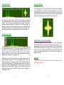
RadioCom 4.5
DSP-Filter Decoding with the Computer
RTTY-, CW-, PSK , Fax-, SSTV- Decoding,
with Frequency-Management und Frequency-Analyzer
User’s Manual
Contens
Basic requirements:................................................................................................. 1
Installation: ....................................................................................................... 1
Sounds System Adjustments: .......................................................................... 1
Short Info:......................................................................................................... 3
Expansion and Update: .................................................................................... 3
Technical Service: ............................................................................................ 3
Radio Control:.......................................................................................................... 4
Tab Tool Window: ............................................................................................ 5
Transmit and Receive Frequency: ................................................................... 6
Reception, Adjustments and Tuning: ............................................................... 7
Signal Tuning – What is a useful signal? ......................................................... 8
Adjustment Helps: ............................................................................................ 9
Frequency Spectrum:....................................................................................... 9
X/Y Tuning Display:........................................................................................ 10
Speed Problems of the Tuning Display:......................................................... 10
Q/B PSK: ........................................................................................................ 10
RTTY-Decoder ...................................................................................................... 11
Save Text/Load/Print:..................................................................................... 11
MODE:............................................................................................................ 12
Baud rate:....................................................................................................... 12
Shift and Mark Frequencies: .......................................................................... 12
Stop Bits: ........................................................................................................ 12
Polarity: .......................................................................................................... 12
FAX-Decoder ....................................................................................................... 13
Picture Receiver: ............................................................................................ 13
Save: .............................................................................................................. 13
Save FAX Buffer:............................................................................................ 14
Module and Slant Correction (IOC Part): ....................................................... 14
Drum Speed: .................................................................................................. 14
Shift and Center Frequency: .......................................................................... 14
Filter, Bandwidth:............................................................................................ 14
Spectrum Analyzer: ........................................................................................ 15
View and Edit Weather maps (Fax)....................................................................... 16
Load Fax: ...................................................................................................... 16
Save or Print Fax:........................................................................................... 17
+/- Zoom Sector Enlargement: ....................................................................... 17
Fax Over-view and Edit Pictures:.................................................................. 17
Invert Picture: ................................................................................................. 18
Rotate Picture:................................................................................................ 18
Nice Effect: ..................................................................................................... 18
ICO RPM: ....................................................................................................... 18
Outline, Soften, Sharpen, Brightness:............................................................ 18
Change Color Palette: .................................................................................... 18
CW Decoder .......................................................................................................... 19
Save and Print:............................................................................................... 19
Select Font: .................................................................................................... 19
Adjustment Help: ............................................................................................ 19
Center:............................................................................................................ 19
Width: ............................................................................................................. 19
SSTV Decoder....................................................................................................... 20
Tuning: ........................................................................................................... 21
Mode: ............................................................................................................. 21
SSTV-FREQ:.................................................................................................. 21
AVIS: .............................................................................................................. 21
SSTV SLANT Correction:............................................................................... 21
Audio-Decoder:...................................................................................................... 22
Recorder:........................................................................................................ 22
Filter / Equalizer: ............................................................................................ 24
Freqency Scanner: ......................................................................................... 24
Basic requirements:
SSB Transceiver or Receiver
Windows 95/98/ME/2000/XP and NT4.0 SP3 or higher
INTEL® Pentium 150 MHz CPU, 64 MB RAM
Graphic-Card: Min. high color (16 bit), 800x600
Bi-directional soundboard 16 bit stereo with line input
Further basic requirements will be given by the system.
Installation:
1) Insert the RadioCom 4.5 CD and enter the section number located on the CD
into the RC45 key number box and install the RadioCom 4.5.
2) Connect the audio from the radio’s speaker output jack to the soundcard’s
microphone or LINE-IN jack. If you want the program to control the radio you
need to connect the radio to the ‘Switchbox’ via a 9-pin connector and cable
constructed from the provided wiring diagrams. The wiring diagrams are on
the CD in the chapter “Technical Service”. A small switch modem/level
converter (sometimes also called a ‘DONGLE’) will plug into any free/spare
Com/Serial-Port available on the computer. There are 3 different switch
modems available:
a)
b)
Sounds System Adjustments:
If the typical sound card is properly installed you will hear the normal wave sounds from
your system. If you do not have the sound card installed you will need to do that now. The
basic controls and uses are all described in the windows help sections. The sound mixer
control panel is the one where you will be adjusting the input and output sound levels for
the proper operation of the program. Adjust the volume so that you can hear the receiver
through your computer speakers. Further check that the adjustment displays, for indications
of audio being detected by the program.
NOTE: If you are not getting any audio from the computer speakers check the LINE-IN
control to see if it is turned on. If you have a microphone plugged in it must be turned off so
that it will not give any false or extraneous sounds to the program.
The IC-SWL is used for the ICOM radios with original Remote-control.
The RC-SWL and RC-HAM switch modems are used for nearly all radios.
3) Sounds System Adjustments: If the typical sound card is properly installed you
will hear the normal wave sounds from your system. If you do not have the
sound card installed you will need to do that now.
The basic controls and uses are all described in the windows help sections. The
sound mixer control panel is the one where you will be adjusting the input and
output sound levels for the proper operation of the program. Adjust the volume so
that you can hear the receiver through your computer speakers. Further check;
The adjustment displays for indications of audio being detected by the program.
NOTE: If you are not getting any audio from the computer speakers check the
LINE IN control to see if it is turned on. If you have a microphone plugged in it
must be turned off so that it will not give any false or extraneous sounds to the
program.
you find this driver
in the part of Audio-Decoder
Within of the RadioCom 4,5 Install you can select between two colour versions
(blue and green), therefore in this manual you can find also sometimes different
outfits of the windows and characteristics which you only find on Windows XP.
1
2
Short Info:
These operating instructions are not for amateur radio. An assumption is made
that you know how to operate your radio. If not, you should first get used to using
your radio.
RadioCom includes small helps. They will show up when the mouse is on a tool
bar or window. A popup called a ToolTip will display. This will show the function of
the respective toolbar or window. If you press the right mouse button from the
‘Context Menu’ you will get further information. This is very important for optimal
use.
Expansion and Update:
The program is built so that later updates will extend and expand the basic
functions. Provided are sending and receiving programs, analyzing tools for the
radio data decoding and new functions. The update service is only available on
the Internet at www.bonito.net. Large updates/upgrades will be released on
CD.
In the moment already RadioCom 5.x is available.
Technical Service:
The whole technical service is placed on the CD and you will find the latest
changes on the Internet.
RADIO CONTROL
The main window includes the most
important control elements for controlling
the radio. You should be familiar with
these functions. Your radio may not
support/have all functions. Frequencies
can be entered or dialed up and down by
clicking the tuning knob on the left for
down or the right for up. The step size is
determined from a drop down menu
when you click the button.
The NB button (NOISE BLANKER) will
eliminate static and crackling noise. With
AGC you can stabilize the incoming
signal if the station is not constant. The
signal strengths can be controlled on the
scale high left on the screen. If a signal is over S7 you can use the button ATT.
(Attenuation) This diminishes the antenna, if the signal is to strong and the
receiver is prone to distortion.
The UBS, LSB, CW, AM, FM, WFM are modes. For most digital receiving you
should basically use USB with a bandwidth of 3 kHz IF. AM is used for normal
radio stations on short wave where 6 kHz is used. Air traffic stations use 15 kHz
on frequencies from 87 to 106 MHz.
Different modes will be activated or deactivated by the program, depending on the
radio you are using. SQL is the squelch, which eliminates interference when there
is no signal being received. VOL is the volume control. It controls the volume
function on the soundcard, not the radio.
The band selectors 80m - 23cm switch a frequency, which are dependent on the
decoder mode of operation (RTTY, CW, PSK, FAX, SSTV).
On the field MousePad - FrequencySlider you must click and holds the mousebutton and then slides to the left or right. Depending upon that, as far the
frequency will push you more or less strongly adjusted. The switching surface X.
places the frequency movement 100 times more largely.
3
4
Tab Tool Window:
Transmit and Receive Frequency:
The illustrated fields are for choosing the different functions of the program.
They are:
AUDIO
; sound adjustments, speaker, equalizer
; Filter, audio recorder and frequency scanner
FAX
; receiving faxes and setting the parameters
SSTV
; receiving SSTV and setting the parameters
RTTY
; receiving RTTY and setting parameters
CW / PSK
; receiving CW and PSK and setting parameters
TIME-Signals ; Time signal decoder for German DFC77 und British MSF
The program and the DSP filter will work right only by activating the particular
decoder. The FAX is activated in the example. The result is that only the FAX
window is actually working now. Other windows can be made visible but they do
not make useful displays.
You have a list, which contains the important data for the receiver and transmitter.
By double clicking on the frequency line you transfer that data to the program and
the radio. If you press the space bar you will switch to that the frequency. Double
click/ENTER will start the respective decoding process. If you press the headerline (e.g. Name) the list will be sorted.
You can make a new entry, change
the existing data, save, sort or delete
entries by using the right mouse
button and choosing the function you
want from the popup menu.
RadioCom 4.5 WorkBench structure
The correct way to enter new data is
to select the mode, receive
frequency and adjust the parameters
for proper operation. When you are
satisfied choose “ADD A NEW LIST
ITEM” from the context menu and all
the parameters in the appearing
window should be entered. All that
you enter here will be loaded by a
double click from now on.
5
6
Reception, Adjustments and Tuning:
Signal Tuning – What is a useful signal?
The quality of reception is affected by a lot of factors. The antenna and the quality
of the receiver are the biggest. A good antenna can be constructed by taking 6
meters of wire and connect it to the center conductor of a piece of coax long
enough to reach from outside to the radio. Take another piece of wire 6 meters
long and connect it to the shield of the coax. Make sure the connections are
waterproof and will hold up to the pull from the wire. Secure the ends of the wire to
a rope and raise both ends off the ground making a ‘T’. As higher the better. This
is a simple DIPOLE antenna.
A digital signal is comprised of different sounds or pitches. The distance in time
between the first and the last tone is called bandwidth. Good digital signals will
always be concise and different from all other sounds. You just have figure out
what kind of signal it is; MORSE, RTTY, SSTV or FAX.
“Nobody has offered us an antenna, which is better”
There are different types of antennas, verticals, active antennas, loop antennas
and so on. We offer a special antenna, but we never say that our antenna is better
than a perfect wire. Our antenna is only better than all other compromises when a
wire antenna can’t be constructed. And they all were tested.
You will soon be able to detect what the signals are by the sounds. We only
decode NAVTEX SITOR and RTTY. But there are a lot of different modes sent
over the air. We do not decode these (BUT OPTIONS ARE AVAILABLE).
Therefore, a meaningless signal may be a useful signal. There are signals, which
we are decoding correctly, but the letters have no meaning. It might be a foreign
language or a cipher code. Which would be not readable.
Even if you receive correct synoptic number codes you may think they are
useless. This data can be weather data, which will be automatically decoded by
the program.
At first try a clear frequency. If you receive a bad signal you may have to optimize
the antenna or you might wait until the conditions are better. If you try and work
with a signal that has lots of interference it will be difficult to interpret the elements
of the tuning and the functions.
“How to adjust something you can’t see or hear?”
If you have adjusted the signal as best as you can with good receiving conditions
you can also decode it by worth conditions. (???) The tuning and the parameters
in the frequency list are already saved and because of that you can call them up
again. It will not be necessary to make the adjustments again. By doing that you
will see what the decoder can do. It can work well because the decoder does not
register interference’s like the human ear. The speaker will reproduce everything
exactly like it comes in. So you hear a lot of things that the DSP filters out.
7
8
Adjustment Helps:
X/Y Tuning Display:
On the preceding page a RTTY signal was used as an example whose adjustment
is now displayed on the X/Y display. Get the signal between the red lines (Shift)
by using the frequency spectrum. Then get the cross. If that will not work, you can
play a little bit with the shift. If the shift is correct, the bars will be placed vertical on
top of each other. Finally make sure the crossbars are perpendicular.
You’ll need help in tuning to adjust a signal to make the program work correctly.
The tuning helps will show you where the signal is located and the interference
around it. You will be able to tune the signal in real-time visually. The Scope bar
contains the Spectrum Analyzer, X/Y Tuning Display, and the Signal Scope. The
adjustment helps are shown in the upper part of the screen. They show the
incoming audio so that you can adjust the characteristics from the radio. Slowly
rotate the tuning knob and see how the program reacts to the changes made.
Frequency Spectrum:
Speed Problems of the Tuning Display:
All the audio is displayed and is marked from left to right. The height corresponds
to a stronger amplitude sound. You will see how amplitude will depend on the
pitch. Always try and find that has the highest amplitude. There are exact
technical instructions for which pitch the system is set for. But in practice it
depends on the filter curves of the radio. The unedited frequency list is always
theoretical and not adjusted to your individual radio.
When tuning you should take care that the signal is placed exactly on the red
lines. The distance between the lines is the bandwidth (called ‘SHIFT’). The
horizontal numbers on the scale show the pitch and the vertical lines show the
volume. This picture shows a RTTY signal with two different pitches. One for Mark
and the other is Space. Both sounds should be placed exactly on the red line.
During a fax signal the bandwidth is higher, the red lines farther apart, with the
major signal on the red line to the right. The adjustment process is explained in
that part of the manual.
9
The adjustment displays use a lot of CPU cycles and resources. Combined with
other demands made on the system you might encounter problems if your
processor has a low clock rate. You can close the RTTY or FAX tasks by pressing
CTRL/ALT/DEL and ending the task. Using the Kernel CPU option located in the
System-Tools section under the System Monitor. This shows CPU usage and if
you can risk opening another window. You can right click the mouse on the
display and turn it off.
Q/B PSK:
In PSK mode you will have bright patches in the middle of the display when the
signal is properly adjusted.
10
RTTY-DECODER
MODE:
Baudot: This mode refers to the usual RTTY mode and is an asynchronous
mode. SYNOP announcements are also sent in this mode.
Sync Baudot: This mode manually synchronizes the Baudot mode.
Sitor B: This is a synchronous mode. It uses a self-error correcting method that
reduces interference problems. Navtex uses a form of this called FEC, Forward
Error Correcting, and is at 100 baud rate.
Baud rate:
Baud rate is derived from Baudot. It is the speed of the data bits when using
RTTY mode. The most common baud rate is 50 baud but commercial stations for
weather reports often use 75 to 100 baud. Navtex in Sitor-B mode is 100 baud.
Shift and Mark Frequencies:
The shift is the distance in time between the two audio frequencies, sounds, which
determine the RTTY byte or character. It is shown on the frequency analyzer by
the two red lines. The mark frequency determines the position of both red lines
and the shift determines the width of the lines.
Stop Bits:
This is how the main screen looks when you are in RTTY mode. The RTTY LIVE
VIEW window shows the received text. Normally you see the last line that is
coming in live. If you want to see saved text you have to click on the RTTY TEXT
VIEW window.
Each character sent in Baudot must have a start bit and either 1.5 stop bits or 2
bits. This arrangement of bits is what determines the code of the character.
Polarity:
Save Text/Load/Print:
The whole text message is saved in the text memory. You can save a marked part
of a message. You can load the text again in a similar way. The text will be saved
as a RTF file. RTF files can be read, edited and printed by Notepad and WordPad.
To use these functions right mouse click while in the RTTY TEXT VIEW window
and choose the desired function from the popup menu.
Most receivers and transceivers have USB and LSB functions. Digital data can be
sent in either mode. Most of the time stations use USB. If you are not able to
decode a station correctly you can try and INVERT the signal. The LE and FI
buttons stand LETTERS and FIGURES. There are times when in decoding
Baudot the decoder will get ‘HUNG UP’ in figures or letters. You can force he
program to change by clicking these buttons.
Enlarge a big text viewer with a double-click into the text field.
A double-click in the field of the File requester enlarged them too.
11
12
FAX-DECODER
Save FAX Buffer:
If you want to save a Fax manually you have to press the ‘Snapshot’ button. The
whole picture will be saved. You can view and edit the picture with the big View
Fax option.
Module and Slant Correction (IOC Part):
Weather Fax’s usually use an IOC of 576 sometimes 288.
Radio amateurs use 267.
IOC 267:
IOC 288:
IOC 352:
IOC 576:
Direct reception of Meteosat and amateur pictures.
Small weather maps with about 800-pixel resolution.
Press pictures with about 1100-pixel resolution.
Large weather maps with about 1800-pixel resolution.
You can also adjust the slant of a Fax picture. The first time you run the program
the picture will probably be slanted. If that does occur you can adjust the picture to
the left or right by using the “< >” buttons. When you are satisfied with the slant
correction click on the ‘Calc to all’ button. This saves the correction factor and you
won’t have to do this again.
Drum Speed:
Picture Receiver:
This window is usable when you receive a fax. It is displayed in reduced size.
Right click on the fax window and select the 1:1 big view or make a double-click in
the fax window.
The drum speed for most pictures received is 120 RPM. Maps from Moscow come
with different speed like 60, 90, or 120.
Shift and Center Frequency:
Save:
Activating the AutoSave button will start saving the picture from now until the stop
signal is received. Normally the program will do this automatically with the
incoming start signals. The ‘Save This Now’ is deactivated when you start the
program. The picture may not be synchronized at this moment: press the right
mouse button on the margin and the picture will become left synchronized. Click
on the LED you change the state of save.
13
Sometimes it is advisable to move the adjustment of the high signal area to the
low. This helps to eliminate unwanted signals. This means you have to move the
two red lines on the horizontal scale of the frequency spectrum display.
Filter, Bandwidth:
You can adjust the filter and the passage area of the filter (brighter area).
The filter should go beyond the shift. Other adjustments can make improvements.
14
Spectrum Analyzer:
VIEW AND EDIT WEATHER MAPS (FAX)
This is the display for adjusting the sound frequency. Using USB the fax signal will
have a pile of bars, which deflects to the end of the left red line. The bright area
shows the filters sphere of activity. For getting clear white pictures, the main bar
should be located before the red line on the right. If there is interference you can
move the center frequency up or down to minimize the bandwidth or change the
filter.
A received weather map is a BMP picture. You can edit the Bitmap with standard
programs. However there are special tools missing to change or improve the
problems of the fax reception. With this program you can turn, synchronize and
edit fax pictures much faster because it is especially designed for our application.
Load Fax:
You can load a picture with the usual disk requester. When you select a picture
file to load a thumbnail picture is shown on the left side of the window. If there are
no pictures to preview you have to deactivate the display option “No MS-DOS
extension” in the windows explorer under “view options” because we need the
display of such MS-DOS extensions.
15
16
Save or Print Fax:
Invert Picture:
You can save and print the picture using the usual edit window icons.
You can receive a fax picture reversed if you use LSB. You should do this to get a
better quality picture. The picture is a negative and you can invert it to make it
white.
+/- Zoom Sector Enlargement:
The picture can be enlarged or reduced with the plus or minus keys. In the overview mode it is possible to choose a sector with the mouse one at a time.
Rotate Picture:
If the picture placed wrong on the screen you can rotate it until it is in the right
position.
Fax Over-view and Edit Pictures:
When this control panel is activated the whole picture will be shown full screen. In
this over-view mode the following left control panel is active and the picture can be
manipulated.
Nice Effect:
This effect will show the picture with full pixel rate.
ICO RPM:
Synchronize:
You received a picture in which the left edge is located in the center of the screen.
Use this function to synchronize the picture. Click on the control icon and then
click on the position where you want the left edge to be in the future.
If a fax was recorded with the wrong IOC speed you can make it readable with this
function.
Outline, Soften, Sharpen, Brightness:
Slant Correction:
If a picture is slanted, choose this icon. Click on the top edge of the picture and
pull down a line along the sloping pass of the picture. Click one more time and the
picture will be corrected.
The outline icon will make isobars clearer. If a line was recorded very weak you
can improve it with this effect. The Soften and Sharpen icons add sharpness or
less sharpness to the picture. Brightness will change the contrast.
Change Color Palette:
Just like most graphic programs you can change the color of a picture. This is very
popular for satellite pictures.
Cut Picture:
Click on this icon and create a rectangle. The rectangle will stay on the screen
waiting for you to press the right mouse button to cut out that part of the picture.
You can move the edge later with the mouse button. Click on the edge with the
left mouse and keep it. Then you can move the flashing line to the desired
position.
17
18
CW DECODER
The CW program is like the RTTY program. Tune the signal to the red line. You
can do this by frequency or with the mouse moving the signal into the filter
(Provided the program is controlling the radio). Adjustment of the filter width is
from 10 Hz. to 2.3 kHz. You can change the center frequency with the center
control. The ‘POS’ and ‘Zoom’ controls will change the position of the signal.
Save and Print:
You can print and or save received text or just marked text.
SSTV DECODER
Looking at the Picture Receiver/Explorer window the left part of the window will
show the received picture. The center will show the saved picture and the right will
show the file name of the saved picture. You can select a file name and load a
saved picture into the editor. If you double click the picture in the receive part of
the window it will be displayed 1:1.
Select Font:
This allows you to change the font style of the displayed text.
Adjustment:
The signal will have to be tuned so that it is exactly on the red line.
Center:
Use this control to move the filter horizontally. This will change the center
frequency.
In the control section of the screen you will be able to work with the filtering
options. There is a quick select function for changing frequencies. This is in a box
labeled SSTV-Freq.
With the ‘M+’ button it is possible to save a tuned frequency. If you tune to
something new you can return to the old saved frequency with the ‘M-‘ button.
Width:
This control changes the bandwidth of the filter.
19
20
Tuning:
AUDIO-DECODER
A small bright area will be visible on the left of the frequency spectrum. This
appears sometimes on the red line. The red line indicated the synchronizing of the
signal at 1200 Hz. You should tune until the whole signal fits in the marked filter
area. Good tuning shows clear colors. Off shades signify improper tuning. The
filter section has 3 variable adjustments, one manual and 3 preset selection’s ‘LO’
‘MED’ and ‘HI’.
Mode:
You can choose between the 4 different modes.
Martin 1, Scottie 1/2 and Robot 72.
SSTV-FREQ:
These buttons change the radio to different preset frequencies in the program.
AVIS:
There is a start signal in a SSTV signal. This automatically starts the reception of
a picture and saves it at the end of the transmission. This does always work. You
will have to press Receive to start reception. Autosync will try to synchronize the
picture. Pressing the ‘Autosync’ button will resynchronize the picture until the
colors are right. Then you can correct the picture with ManuSync placing it the
proper position.
SSTV SLANT Correction:
You can correct the slant of a picture by using the ‘10x or 1x’ slant buttons. You
should press and hold the button until the picture is straight. The correction factor
is either 10 pixels or 1 pixel per single click of the button. Pressing and holding the
button will provide a quicker correction.
The essential characteristic of the program is the sound-processing-system
together with DSP from your soundcard. This is called DSP. You need to know
following things: The signal will be read in with line-in (or with the microphone
input). Then it will be checked 11000 times per sec. which parts of the frequency
this signal got. This we call sample-frequency. After it goes through different
complex software processes, which we call filter. The signal is giving out parallel
with listening. You can choose, if you want to hear the input directly (Signal-IN
ON) or after the run through of the filter (Wave-Out ON). If you want to listen to
the output, you need a bidirectional soundcard. In this case it’s advisable to
deactivate Signal-IN ON. Pay attention to adjust the controller that way, that
there is no over modulation (red area). To turn off the receiver-listening tone use
the switch Signal-IN ON. This one
only turn off the received signal.
Other tones from the system are
still hearable. If you turn off the
speaker (ON), there is no tone out
of the speaker - and no sound
system message too.
The ‘Save This Now’ button will save the picture in the receiver window. The
‘AutoSave’ button will save the picture when the lower edge is reached. You can
load and print the picture.
21
These options normally can be
adjusted with the audio-mixer driver
of the sound volume control. In this
program part we try to respond
these sound-drivers. The program
tries to find the necessary
components. It didn’t work always.
Therefore we offer an expedient.
Some drivers appears, if you press
the Driver button.
22
Audio-Recorder:
Filter / Equalizer:
The equalizer can be used like you draw a picture with the mouse. Click anywhere
and keep the button down and draw the desired curve of the filter. If you press the
right button the position will be brought to the maximum.
Activate Decoder filter to Wave-Out:
The Equalizer-Filter will be switched over to the ‘Wave Out’.
The signal recorder is used for recording or playing back signals.
Play
1. Press = Playback of a wave file
2. Press = Stop
Halt
1. Press = Stop Playback
2. Press = Playback will go on
Loop
1. Press = Repeats playback
2. Press = Playback one time
If you press the ‘WavePlay as Signal In’ button in the Audio Control menu the
wave file becomes the signal input. The volume can be adjusted by the volume
control. Pressing the record button with the REC symbol (the Red Point) activates
a recording of the signal. The input signal is recorded and the recording volume
depends on the control next to the record peak meter. If a wave file is running and
the button ‘WavePlay’ is active as ‘Signal In’ in the audio control panel the signal
will be recorded as the input. There is a slide control below the audio scope that
will allow you to move through the wave file. In the compressor control panel you
can select the type of compression you want to use if you desire. For exact
analysis of a signal you should use PCM 11025 HZ / 16 bit, mono, 22 kb/s mode.
During some compression types will loose important parts of the signal. The file
list has got a context menu for delete, rename, list refresh, change folder and info
about the select wave file.
23
Frq Scan:
Only
the
selected
frequencies from the
list will run. Pressing
the start button starts
the scan. The last
parameters set in the
radio control panel will
be used. Only the
frequency is changed.
The audio or squelch
signals as used for
that. A signal event
occurs when a signal breaks through the squelch and the audio becomes useable.
Not all receivers have a squelch control. That is why audio squelch (the control on
the Audio Control panel) ‘Asql’ is a much better squelch. It evaluates the
interference much more effectively as compared to signal strength.
The scan process stops when the ‘stop on Audio’ or ‘stop on Squelch’ is pressed.
The maximum delay time can be controlled by the value set in ‘Stop-Time’. A
value of zero (0) means the process is stopped until the signal is off.
By changing the values of start, stop and step and press the ‘Make New List’
button a new list of frequencies is created. You select what frequencies you want
by clicking the small box next to it. If you want to skip a frequency do not check
the box.
24