1
AllenBradley
ASCII I/O Module
(Cat. No. 1771-DA)
User
Manual
Table of Contents
To Our Customers . . . . . . . . . . . . . . . . . . . . . . . . . . . . . . .
11
Overview of This Manual . . . . . . . . . . . . . . . . . . . . . . . . . . . . . .
Intended Audience . . . . . . . . . . . . . . . . . . . . . . . . . . . . . . . . . . .
Notational Conventions . . . . . . . . . . . . . . . . . . . . . . . . . . . . . . . .
Some Tips on Using This Manual . . . . . . . . . . . . . . . . . . . . . . . .
Typical Applications . . . . . . . . . . . . . . . . . . . . . . . . . . . . . . . . . .
11
11
11
12
13
Getting Started With Your ASCII Module . . . . . . . . . . . . . .
21
PLC2 Family Processors . . . . . . . . . . . . . . . . . . . . . . . . . . . . . .
What You Need to Get Started . . . . . . . . . . . . . . . . . . . . . . . . . .
Reading Data from Your ASCII Device . . . . . . . . . . . . . . . . . . . . .
Writing Data to Your ASCII Device . . . . . . . . . . . . . . . . . . . . . . . .
PLC3 Processors . . . . . . . . . . . . . . . . . . . . . . . . . . . . . . . . . . .
What You Need To Get Started . . . . . . . . . . . . . . . . . . . . . . . . . .
Reading Data from Your ASCII Device . . . . . . . . . . . . . . . . . . . . .
Writing Data to Your ASCII Device . . . . . . . . . . . . . . . . . . . . . . . .
22
22
210
214
218
218
228
232
Choosing Module Features . . . . . . . . . . . . . . . . . . . . . . . .
31
Chapter Objectives . . . . . . . . . . . . . . . . . . . . . . . . . . . . . . . . . . .
Choosing the Mode of Communication . . . . . . . . . . . . . . . . . . . . .
Choosing the Mode of Module Operation, IW1(0204) . . . . . . . . . .
Using BCD Delimiters (Report Generation Mode, Only), IW4(1016)
Justifying Margins, IW3(03) . . . . . . . . . . . . . . . . . . . . . . . . . . . . .
Using the EndofString Delimiter, IW3(1016) . . . . . . . . . . . . . . . .
Setting String Length, IW2(0013) . . . . . . . . . . . . . . . . . . . . . . . .
Determining Block Transfer Length . . . . . . . . . . . . . . . . . . . . . . .
Removing the Fill Character (Data Mode, Only), IW4(1016) . . . . .
Removing Header and Trailing Characters, IW4(0003, 0407) . . . .
Choosing I/O Buffer Size, IW3(0002) . . . . . . . . . . . . . . . . . . . . .
Choosing Transmission Mode, IW1(0507) . . . . . . . . . . . . . . . . . .
Choosing Single or Multiple Transfers, IW2(17) . . . . . . . . . . . . . . .
Selecting Delay for Carriage Return, IW3(0607) . . . . . . . . . . . . . .
Setting Remaining Bits in IW1(1017) . . . . . . . . . . . . . . . . . . . . . .
Selecting the Number of Initialization Words, IW1(0001) . . . . . . . .
Recording Bit Settings in Initialization Words . . . . . . . . . . . . . . . . .
31
31
313
314
315
317
318
320
321
323
324
325
325
326
326
329
330
ii
Table of Contents
ASCII I/O Module Tutorial . . . . . . . . . . . . . . . . . . . . . . . . . .
41
Chapter Objectives . . . . . . . . . . . . . . . . . . . . . . . . . . . . . . . . . . .
PLC2 Family Processors . . . . . . . . . . . . . . . . . . . . . . . . . . . . . .
Adding Initialization Rungs . . . . . . . . . . . . . . . . . . . . . . . . . . . . .
Setting Bits in Initialization Words . . . . . . . . . . . . . . . . . . . . . . . .
Expanding the Number of Initialization Words . . . . . . . . . . . . . . . .
Changing the Module's String Length (Read, Only) . . . . . . . . . . . .
Justifying Data . . . . . . . . . . . . . . . . . . . . . . . . . . . . . . . . . . . . . .
Demonstrating EndofString Delimiter . . . . . . . . . . . . . . . . . . . . .
Removing the Fill Character . . . . . . . . . . . . . . . . . . . . . . . . . . . .
Removing Header and Trailing Characters . . . . . . . . . . . . . . . . . .
Demonstrating Data Conversion . . . . . . . . . . . . . . . . . . . . . . . . .
Selecting Report Generation Mode, Data Conversion,
and BCD Delimiter . . . . . . . . . . . . . . . . . . . . . . . . . . . . . . . .
Formatting a SingleLine Message . . . . . . . . . . . . . . . . . . . . . . . .
Formatting a MultiLine Message . . . . . . . . . . . . . . . . . . . . . . . . .
PLC3 Processors . . . . . . . . . . . . . . . . . . . . . . . . . . . . . . . . . . .
Adding Initialization Rungs . . . . . . . . . . . . . . . . . . . . . . . . . . . . .
Setting Bits in Initialization Words . . . . . . . . . . . . . . . . . . . . . . . .
Expanding the Number of Initialization Words . . . . . . . . . . . . . . . .
Changing the Module's String Length (Read, Only) . . . . . . . . . . . .
Justifying Data . . . . . . . . . . . . . . . . . . . . . . . . . . . . . . . . . . . . . .
Demonstrating EndofString Delimiter . . . . . . . . . . . . . . . . . . . . .
Removing the Fill Character . . . . . . . . . . . . . . . . . . . . . . . . . . . .
Removing Header and Trailing Characters . . . . . . . . . . . . . . . . . .
Selecting Report Generation Mode, Data Conversion,
and BCD Delimiter . . . . . . . . . . . . . . . . . . . . . . . . . . . . . . . .
Formatting a SingleLine Message . . . . . . . . . . . . . . . . . . . . . . . .
Formatting a MultiLine Message . . . . . . . . . . . . . . . . . . . . . . . . .
Demonstrating Data Conversion . . . . . . . . . . . . . . . . . . . . . . . . .
Summary . . . . . . . . . . . . . . . . . . . . . . . . . . . . . . . . . . . . . . . . .
41
42
42
44
45
45
47
49
414
415
417
419
421
424
427
427
430
432
432
434
435
440
442
443
446
449
452
455
Handshaking . . . . . . . . . . . . . . . . . . . . . . . . . . . . . . . . . . .
51
Chapter Objectives . . . . . . . . . . . . . . . . . . . . . . . . . . . . . . . . . . .
Understanding Handshaking Fundamentals . . . . . . . . . . . . . . . . .
Reading Status and/or Data from the Module . . . . . . . . . . . . . . . .
51
51
53
Function of Control and Status Bits . . . . . . . . . . . . . . . . . .
61
Chapter Objectives . . . . . . . . . . . . . . . . . . . . . . . . . . . . . . . . . . .
Command Words . . . . . . . . . . . . . . . . . . . . . . . . . . . . . . . . . . . .
Initialization Words . . . . . . . . . . . . . . . . . . . . . . . . . . . . . . . . . . .
Status Words . . . . . . . . . . . . . . . . . . . . . . . . . . . . . . . . . . . . . . .
61
61
63
613
Table of Contents
iii
Troubleshooting . . . . . . . . . . . . . . . . . . . . . . . . . . . . . . . .
71
Chapter Objectives . . . . . . . . . . . . . . . . . . . . . . . . . . . . . . . . . . .
Recognizing Initialization Errors . . . . . . . . . . . . . . . . . . . . . . . . . .
How You Interpret Status Indicators . . . . . . . . . . . . . . . . . . . . . . .
How You Interpret Codes in Status Word One . . . . . . . . . . . . . . . .
Testing the ASCII Module and Cables . . . . . . . . . . . . . . . . . . . . .
71
71
72
74
77
PLC2 Family Processors . . . . . . . . . . . . . . . . . . . . . . . . .
A1
Complete Getting Started Program, PLC2 Family . . . . . . . . . . . . .
Block Transfer Programming . . . . . . . . . . . . . . . . . . . . . . . . . . . .
Block Transfer Timing . . . . . . . . . . . . . . . . . . . . . . . . . . . . . . . . .
Example Read (Only) Program . . . . . . . . . . . . . . . . . . . . . . . . . .
Example Write (Only) Program . . . . . . . . . . . . . . . . . . . . . . . . . .
Example Read/Write Program . . . . . . . . . . . . . . . . . . . . . . . . . . .
Example Application Write Program . . . . . . . . . . . . . . . . . . . . . . .
For PLC-3 Family Processor . . . . . . . . . . . . . . . . . . . . . . .
Complete Getting Started Program, PLC-3 . . . . . . . . . . . . . . . . .
Block Transfer Programming . . . . . . . . . . . . . . . . . . . . . . . . . . . .
Example Read (Only) Program . . . . . . . . . . . . . . . . . . . . . . . . . .
Example Write (Only) Program . . . . . . . . . . . . . . . . . . . . . . . . . .
Example Read/Write Program . . . . . . . . . . . . . . . . . . . . . . . . . . .
Example Application Read/Write Program . . . . . . . . . . . . . . . . . .
A1
A3
A5
A15
A18
A19
A22
A26
A26
A30
A41
A45
A47
A50
For PLC3 Family Processor . . . . . . . . . . . . . . . . . . . . . . .
B1
Complete Getting Started Program, PLC3 . . . . . . . . . . . . . . . . . .
Block Transfer Programming . . . . . . . . . . . . . . . . . . . . . . . . . . . .
Example Read (Only) Program . . . . . . . . . . . . . . . . . . . . . . . . . .
Example Write (Only) Program . . . . . . . . . . . . . . . . . . . . . . . . . .
Example Read/Write Program . . . . . . . . . . . . . . . . . . . . . . . . . . .
Example Application Read/Write Program . . . . . . . . . . . . . . . . . .
B1
B5
B16
B20
B22
B25
ASCII Conversion Tables . . . . . . . . . . . . . . . . . . . . . . . . . .
C1
Specifications . . . . . . . . . . . . . . . . . . . . . . . . . . . . . . . . . .
D1
Preface
To Our Customers
Overview of This Manual
This manual tells you in a tutorial manner how to install and use your
ASCII module.
In Chapter
Entitled
We Will Show You How To
1
Getting Started with
Your ASCII Module
Read data from your ASCII module and write data to it
using an industrial terminal
2
Choosing Module
Features
Choose module features so you can match your ASCII
module with your ASCII device
3
ASCII Module Tutorial
Select and demonstrate module features, and format
messages
4
Handshaking
Program the handshaking logic that controls
communication between your ASCII module and your PC
processor
5
Functions of Control
and Status Bits
Select desired features and read module status by
describing the function of bits in command and status
words
6
Troubleshooting Your ASCII
Module
Interpret status indicators and status codes, and use a
simple program to test your ASCII module.
Appendix
Program block transfer communication and estimate the
time required for read/write handshaking. We have
included numerous example programs
Index
Locate concepts and definitions in the text
Intended Audience
We assume that you are familiar with operating and programming your
Allen-Bradley controller. Because of the functions that your module
performs, your programming skills should include file manipulation and
message formatting. Refer to the Programming and Operations Manual
for your PLC-2 family controller or to the Programming Manual for your
PLC-3 controller.
Notational Conventions
Some chapters in this manual contain examples of how you enter data or
commands. When you read these chapters, remember the following
notational conventions:
1
Preface
To Our Customers
A symbol or word in brackets represents a single key you would press.
These include keys such as [ENTER], [SHIFT], or [ ].
Spaces would be entered as shown, except that the space preceding and
following the brackets is not an entered space. (We put a space before
the left bracket and after the right bracket to make it easier to read).
Numbers and capital letters not in brackets would be entered as shown.
Punctuation such as commas, and symbols such as / would be entered
as shown.
For example, typical data and a typical command that you would enter on
the industrial terminal keyboard are as follows:
Enter: ALLEN 123/AB[ENTER] (data)
Enter: DD,O3:0,[SHIFT]%A[ENTER] (PLC-3 command)
We have included numerous examples of CRT displays resulting from
data or commands that you enter. All CRT displays are shown with a
shaded background. Enter all commands on the industrial terminal
keyboard. The only exception is for some PLC-3 entries where we tell
you to use the PLC-3 front panel.
Some Tips on Using This Manual Read chapters 1 and 2 before proceeding to other chapters of this manual
that pertain to your needs. For example, you may want to use only
selected module features (chapter 3) and read only selected bit
descriptions (chapter 5).
We have developed forms to assist you in selecting module features and in
troubleshooting. Make a copy of each of the following and refer to them
as needed.
Initialization Words for Data Mode
Initialization Words for Report
Generation Mode
Command and Status Words
Fault Status
2
Form 5175, chapter 2
Form 5176, chapter 2
Figure 5.2-5.4 chapter 5
Table 6.E, chapter 6
Preface
To Our Customers
You will use several procedures frequently in the tutorial chapters of this
manual. You may want to memorize the steps or have a reference copy of
the following procedures:
Reading Data From Your ASCII Device
Writing Data To Your ASCII Device
Setting Bits in Initialization Words
Typical Applications
You can use an ASCII I/O module to input data to the processor from a
data source such as a bar code reader, output messages from the processor
to a display device, or bidirectionally exchange messages and/or data
between an intelligent data terminal and the processor. Typical examples
are as follows:
Devices
Type of
Device
Applications
Bar code readers
Input
Part recognition, sorting, inventory control
Keypads
Input
Enter values, change data
Dotmatrix scrolling
displays, terminals, or
printers
Output
Display warnings or diagnostic messages,
print production reports
Intelligent data
terminals
Input/Output
Enter values, change data, monitor or
troubleshoot a process
Computers
Input/Output
Exchange data files
3
Chapter
2
Getting Started With Your ASCII Module
ASCII is the acronym for American Standard Code for Information
Interchange. The standard includes a 7-bit code for 128 data and control
characters.
With your ASCII I/O module you can transfer data, by means of the I/O
scan, from an ASCII device to the PC processor data table, and vice versa.
The module has two modes of operation, data mode and report generation
mode. In data mode, you can transfer ASCII, BCD, or hex characters.
Generally, use this mode to transfer data to the processor data table. In
report generation mode, you can include BCD values in the string of
ASCII characters. Generally, use this mode when you want to transfer
messages.
You can use your ASCII module with any Allen-Bradley programmable
controller that has an expandable data table, block transfer capability, and
uses the 1771 I/O structure. If you use a PLC-2/20 controller (cat. no.
1772-LP2), your programming will be lengthier because its processor
does not have file move or block transfer instructions.
Getting Started with Your ASCII Module is a hands-on exercise. By
going step by step through two easy examples, you will quickly learn
operation of your module’s basic features.
This chapter is divided into two sections, one for PLC-2 family
processors, the other for PLC-3 processors. Proceed to the section that
pertains to your processor.
21
Chapter 2
Getting Started with Your ASCII Module
PLC2 Family Processors
What You Need to Get Started
You will demonstrate the operation of your ASCII module by reading data
from the industrial terminal to the processor data table, and by writing
data from the data table to the industrial terminal. You will use your
industrial terminal as an ASCII device for entering data (read), and for
displaying data (write).
You will need to set up a PC processor with an I/O chassis, power supply,
industrial terminal, cables, and your ASCII module. You will need about
an hour to complete the tutorial exercises in this chapter, and about two
hours to complete those of chapter 3, once you have the equipment
operating properly.
Equipment That You Need
You will need the following equipment (Table 1.A) using your existing
system and/or spare equipment.
Table 1.A
Equipment (PLC2 Family)
Equipment
Catalog Number
ASCII I/O module
1771DA
Industrial Terminal
1770T3
PLC2 Family Keytop Overlay
1770KCB
Alphanumeric Keytop Overlay
1771KAA optional
Processor Interface Cable
1772TC
IT/DH Adapter Cable
1770CB (figure 1.4)
I/O Chassis
1771A1, A2, A4
Processor PLC2/20, 2/30
22
Power Cable
1771CJ, CK
I/O Interconnect Cable
1777CB, CA
Local Adapter Module
1771AL
Termination Plug
1777CP
Chapter 2
Getting Started with Your ASCII Module
or
Processor MiniPLC2/15
Power Supply
1771P1
Power Cable
1771CL
Note: You must use battery back-up.
The ASCII module draws 1.3A from the backplane. Be sure that the total
current drain of all modules in the chassis does not exceed the maximum
for the backplane and power supply.
If you use an existing system, consider disconnecting all other chassis
except the one containing your ASCII module. Disconnect field wiring
arms from output modules for safety purposes.
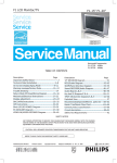
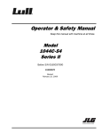
How to Connect Your Equipment
Connect your equipment with the appropriate cables (Figure 1.1 for
Mini-PLC-2/15 controllers, Figure 1.2 for PLC-2/20 or-2/30 controllers).
Be sure that the end of your IT/DH adapter cable labeled CHANNEL B is
connected to channel B on the industrial terminal.
23
Chapter 2
Getting Started with Your ASCII Module
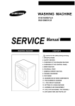
Figure 1.1
Connections for MiniPLC2/l5 Controller
1771-P1
Power Supply
Mini-PLC-2/15
Processor
Module Group 1,
Slot 1
See WARNING in section titled How
to Connect Your Equipment." Using Channels
A&B
Channel A
1770-T3
Industrial Terminal
(rear view)
1771-DA ASCII
I/O Module
1771-A1, -A2, -A4
I/O Chassis
1772-TC
Processor Interface Cable
Channel B
1771-CL
Power Cable
24
1770-CB IT/DH
Adapter Cable
11817
1.
Connect the power cable between the power supply and the I/O
chassis. The cable connects to the backplane of the I/O chassis
behind the processor/adapter slot.
2.
Connect the processor interface cable between the PC processor and
channel A on the industrial terminal.
3.
Connect the IT/DH adapter cable between the ASCII module and
channel B on the industrial terminal.
Chapter 2
Getting Started with Your ASCII Module
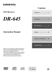
Figure 1.2
Connections for PLC2/20 or PLC2/30 Controller
PLC-2/30
Processor
See WARNING in section titled How
to Connect Your Equipment." Using Channels
A&B
1772-TC Processor
Interface Cable
Channel A
1770-T3
Industrial Terminal
(rear view)
1771-CA, -CB
I/O Interconnect
Cable
1771-AL Local
Adapter Module
1771-CK, -CJ
Power Cable
Channel B
Module Group 1,
Slot 1
1771-DA ASCII
I/O Module
1770-CB IT/DH
Adapter Cable
1771-A1, -A2, -A4
I/O Chassis
1777-CP
Termination Plug
11818
4.
(PLC-2/20, -2/30, only) Connect the I/O interconnect cable between
the PC processor and the I/O adapter module
If the IT/DH adapter cable is too short or not available, make your own.
It should not exceed 50 feet (Figure 1.4).
Using Channels A and B
You may or may not be able to connect cables to channels A and B at the
same time depending on the revision of your industrial terminal.
25
Chapter 2
Getting Started with Your ASCII Module
Industrial terminals manufactured before May 1982 allow cross talk
between channels A and B. As a result, data table values could be altered.
Therefore, you should alternate cables between channels for the tutorials
of this manual when using these terminals. When using a series A
industrial terminal, you must alternate cables.
Your industrial terminal has a date code stamped in white on the upper
right corner of the rear label. If your industrial terminal (cat. no.
1770-T3/TA series B) is date coded T 8218 or earlier, or is not date coded,
alternate cables and observe the following warning:
WARNING: When cables are connect to channels A and B at
the same time, cross talk between these channels could cause
the processor to misread inputs and/or misapply outputs, with
possible damage to equipment and/or injury to personnel. For
this reason, do not remove the slide bar that prevents you from
connecting cables to channels A and B at the same time.
If your industrial terminal (cat. no. 1770-T3/TA series B) is date coded T
8219 or later, you can use channels A and B at the same time.
If alternating between channels A and B, connect the 1770-CB cable to
channel B when using the industrial terminal in alphanumeric mode as a
data terminal. Connect the 1772-TC cable to channel A when using the
industrial terminal in PLC-2 (ladder diagram) mode.
As an alternative, use a second industrial terminal in alphanumeric mode
on channel B, or use a Silent 700 data terminal. Connect either to the
1770-CB cable.
Checking ASCII Module Configuration
Your module is configured for RS-232-C operation when shipped from
the factory. If you suspect that its internal configuration (settings of
internal programing plugs) has been altered, you should check module
configuration (refer to section titled Choosing the Mode of
Communication in chapter 3). Do this as follows:
1.
26
Remove covers from the module’s printed circuit board.
Chapter 2
Getting Started with Your ASCII Module
2.
Locate the programming plugs and set them according to RS-232-C
without control lines (figure 2.8).
Entering the ““Getting Started Program””
You may want to record on tape the ladder diagram of your application
program before proceeding because you will need to load ASCII logic
into a cleared memory for chapters 1 and 3.
Using your industrial terminal, enter the ““Getting Started Program””
(Figure 1.3) into processor memory. At this point, you do not need to
understand how the program works, but you should enter it exactly as
shown.
27
Chapter 2
Getting Started with Your ASCII Module
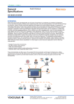
Figure 1.3
Getting Started Program" (PLC2 Family)
LADDER DIAGRAM DUMP
327
020
G
000
02
252
07
020
START
200
PUT
000
200
07
063
TON
063
063
.01
PR 300
AC 000
15
252
17
200
035
15
252
15
200
15
035
15
252
02
00
200
L
00
15
035
252
200
00
15
OFF 15
063
251
020
020
G
=
100
00
01
OFF 15
U
000
020
020
L
01
063
G
000
020
247
OFF 00
=
200
020
U
OFF 00
252
200
L
01
16
ON 16
020
252
200
01
16
U
28
ON 16
Chapter 2
Getting Started with Your ASCII Module
011
BLOCK XFER READ
DATA ADDR:
030
MODULE ADDR: 111
BLOCK LENGTH: 16
FILE:
252 - 271
EN
17
111
DN
17
011
BLOCK XFER WRITE
DATA ADDR:
031
MODULE ADDR: 111
BLOCK LENGTH: 16
FILE:
200 - 217
EN
16
111
DN
16
020
END 00460
02
NOTE: Configure the data table for two racks using [SEARCH][5][0]
before entering this program.
Installing Your ASCII Module
Be sure that power to the I/O chassis is turned off when installing (or
removing) your ASCII module as follows:
1.
Remove power from the I/O chassis.
2.
Insert the ASCII module in rack 1, module group 1, slot 1. The
program makes the processor communicate with the ASCII module
at that specific location. (If you must use another rack location and
are familiar with block transfer operation, change the rack, group,
and slot number of the module address in the block transfer read and
write instructions, accordingly.)
3.
Turn on power to the I/O chassis. Three LED indicators on the
ASCII module illuminate momentarily. Their functions are:
FAULT: Normally off. This red LED indicator illuminates when the
module detects an internal fault.
29
Chapter 2
Getting Started with Your ASCII Module
BUFFER FULL: Normally off. This yellow LED indicator
illuminates when the input buffer becomes full.
CHANNEL ACTIVE: This green LED indicator illuminates when
the industrial terminal is on, properly connected to the ASCII
module’s interface port, and set for alphanumeric mode.
Reading Data from Your ASCII
Device
In this demonstration, you will enter data and observe how it is stored in
the processor data table. You will use the industrial terminal in
alphanumeric mode as an ASCII data terminal when you enter data. Then
you will change the industrial terminal to PLC-2 mode and observe the
transferred data by displaying the contents of the block transfer read file.
You will use the following procedures:
In Procedure
You Will
P1
Set your industrial terminal to alphanumeric mode
P2
Enter your data
P3
Set your industrial terminal to PLC2 mode
P4
See how data is stored in the data table
Later in this chapter and in chapter 3 you will combine these procedures
with others. The order in which you will perform them may vary.
Even if you are familiar with these procedures, we suggest that you read
them completely. If you deviate from them, proper operation may not
occur.
If you have not already done so, load the “Getting Started Program”
(Figure 1.3) into processor memory.
Procedure P1
Set Your Industrial Terminal to Alphanumeric Mode
210
1.
Turn on the industrial terminal.
2.
Insert the Alphanumeric Keytop Overlay (cat. no. 1770-KAA).
Chapter 2
Getting Started with Your ASCII Module
To avoid switching keytop overlays every time you change the industrial
terminal operating mode, you can label numbers, letters, and [RETURN]
on the corresponding keytops of the PLC-2 family overlay.
3.
Select alphanumeric mode.
Press 12 on the keyboard
The ASCII module’s CHANNEL ACTIVE LED illuminates.
4.
Set the communication rate to 300 baud.
Press 13 [RETURN]
The cursor in the upper left corner of a blank screen tells you the terminal
is ready for your input.
5.
Change the processor mode select switch to the RUN/PROG
position. (Failure to do this step now will prevent a transfer.)
Procedure P2
Enter Your Data
1.
Be sure the processor mode select switch is in the RUN/PROG
position.
2.
Enter data such as your first name followed by a couple of numbers.
Enter 11 characters including a space between your name and
numbers (Table 1.B).
211
Chapter 2
Getting Started with Your ASCII Module
Table 1.B
Commonly Used Data Characters
ASCII
Hex
space
0
1
2
3
4
5
6
7
8
9
20
30
31
32
33
34
35
36
37
38
39
ASCII
A
B
C
D
E
F
G
H
I
J
K
L
M
Hex
41
42
43
44
45
46
47
48
49
4A
4B
4C
4D
ASCII
N
O
P
Q
R
S
T
U
V
W
X
Y
Z
Hex
4E
4F
50
51
52
53
54
55
56
57
58
59
5A
The industrial terminal displays the characters as you enter them. If
characters are not displayed, check the program that you loaded into
memory. If you find no errors, refer to Need Help? below.
3.
Change the processor mode select switch to the PROG position.
(Failure to do this step now will prevent correct operation.)
Procedure P3
Set Your Industrial Terminal to PLC-2 Mode
1.
Press [MODE SELECT]
2.
Change the keytop overlay to PLC-2 family.
3.
Select PLC-2 mode.
Press 11 on the keyboard
Procedure P4
See How Data Is Stored in the Data Table
212
1.
Move the cursor to the rung containing the read block transfer
instruction (rung 14). The cursor will illuminate the instruction title
BLOCK XFER READ.
2.
Display the contents of the read block transfer file in hex.
Chapter 2
Getting Started with Your ASCII Module
Press [DISPLAY] 1
Results The industrial terminal displays the name and numbers (first 10
characters) that you entered in step 2. For example,
ALLEN 12345 would be displayed as:
POSITION
FILE DATA
ASCII Equivalent
001
E010
status word one
002
0000
status word two
003
414C
A L
004
4C45
L E
005
4E20
N
006
3132
1 2
007
3334
3 4
Entering the eleventh character caused the module to transfer the data.
Note the space entered between ALLEN and 12345.
The display of status word one (E010) and status word two (0000)
indicates normal status of the module.
3.
Terminate this display by pressing [CANCEL COMMAND], and
return to ladder diagram.
Need Help?
If your display was all zeros, the data did not transfer. You may have
altered the procedure.
Did you enter your program exactly as shown?
Did the module’s CHANNEL ACTIVE LED go on?
Did you perform Procedure P1 before P2?
Did you perform Step 1 in Procedure P2?
Did you perform Step 3 in Procedure P2?
213
Chapter 2
Getting Started with Your ASCII Module
If you are still having trouble, refer to “Testing the ASCII Module and
Cables,” to verify communication between the ASCII module and the
industrial terminal. If you suspect a cable problem, check the 1770-CB
cable (Figure 1.4).
Then try again, starting at Procedure P1.
Figure 1.4
Minimum Connections in the 1770CB Cable
1
2
3
7
* Protective Ground
Transmitted Data
Received Data
Ground
1
2
3
7
18
18
25
25
ASCII Module
Interface Port
Connectors:
25pin DShell
Male Connector
Cable Kit
1770XXP (each
end)
Cable:
Belden 8723 or
equivalent
* In cable but not
required for ASCII
module
Industrial Terminal
Channel B
11819
Writing Data to Your ASCII
Device
214
In this demonstration, you will load data characters into the write block
transfer file and observe how they are displayed. You will use the
industrial terminal in PLC-2 mode to load data. Then you will change the
industrial terminal to alphanumeric mode and observe the transferred data.
Chapter 2
Getting Started with Your ASCII Module
You will use the following procedures where Procedures P1 and P3 are
repeated from the section titled Reading Data from Your ASCII Device.
In Procedure
You Will
P3
Set your industrial terminal to PLC2 mode
P5
Load data into the write block transfer file
P1
Set your industrial terminal to alphanumeric mode (and
observe the transferred data)
Procedure P3
Set Your Industrial Terminal to PLC-2 Mode
NOTE: Skip this procedure if your processor is already in PLC-2 mode.
1.
Press [MODE SELECT]
2.
Check that the PLC-2 family keytop overlay is in place.
3.
Select PLC-2 mode.
Press 11 on the keyboard
The beginning of your ladder diagram program will be displayed.
Procedure P5
Load Data into an Instruction File
1.
Check that the processor mode select switch is in the PROG position.
2.
Move the cursor to the instruction whose file you want to load
(BLOCK XFER WRITE).
3.
Display the file in hex.
Press [DISPLAY] 1
4.
Load new data starting in position 003 for a write block transfer
instruction, position 001 for other file instructions. (Positions 001
and 002 are reserved for command words in a write block transfer
instruction.)
215
Chapter 2
Getting Started with Your ASCII Module
For example, load the following hex codes that are equivalent to
BRADLEY 12345 as follows: (Note the space between BRADLEY and
12345.)
POSITION
FILE DATA
ASCII Equivalent
003
4252
B R
004
4144
A D
005
4C45
L E
006
5920
Y
007
3132
1 2
008
3334
3 4
009
3500
5
Check your display of FILE DATA to be sure that you entered all data
exactly as shown.
Don’t forget to press [INSERT][ ] after entering data in each position.
Use the shift key to enter the hex character C.
Procedure P1
Set Your Industrial Terminal to Alphanumeric Mode
1.
Insert the alphanumeric keytop overlay.
2.
Select alphanumeric mode.
Press [MODE SELECT] 12
3.
Set the communication rate to 300 baud.
Press 13 [RETURN]
The module’s CHANNEL ACTIVE LED turns on.
4.
216
Change the processor mode select switch to the RUN/PROG
position.
Chapter 2
Getting Started with Your ASCII Module
Results The following display appears at the upper left corner of the
industrial terminal:
BRADLEY 12345
5.
Terminate the display and return to ladder diagram. Use the PLC-2
family keytop overlay.
Press [MODE SELECT] 11
Summary
Now that you have demonstrated the transfer of data from your ASCII
device to the data table and vice versa, you are ready to use these
procedures further. First, read the next chapter, “Choosing Module
Features.” It defines key words and concepts. Then in chapter 3, “ASCII
Tutorial”, you will use these procedures to demonstrate operating
characteristics of your module.
217
Chapter 2
Getting Started with Your ASCII Module
PLC3 Processors
What You Need To Get Started
You will demonstrate the operation of your ASCII module by reading data
from the industrial terminal to the processor data table, and by writing
data from the data table to the industrial terminal. You will use your
industrial terminal as an ASCII device for entering data (read), and for
displaying data (write).
You will set up a test I/O chassis with a PC processor, power supply,
industrial terminal, cables, and your ASCII module. You will need about
an hour to complete the procedures in this chapter and about two hours to
complete the procedures in chapter 3.
You may want to record your application ladder diagram program before
proceeding because you will need to load ASCII logic into a cleared
memory for tutorial chapters 1 and 3 in this manual.
Equipment That You Need
You will need the following equipment (Table 1.C) using your existing
system and/or spare equipment.
218
Chapter 2
Getting Started with Your ASCII Module
Table 1.C
Equipment (PLC3)
Equipment
PLC3 Main Chassis
Main Processor Module
I/O ScannerProgrammer Interface Module
Memory Module
Power Supply
Industrial Terminal
PLC3 Keytop Overlay
I/O Chassis
Remote I/O Adapter Module
ASCII i/O Module
Twinaxial I/O Interface Cable
IT/DH Adapter Cable
PLC3 Industrial Terminal Cable
Chassis Power Cable
I/O Power Cable
Terminators
Catalog Number
1775A1
1775L1,L2
1775S4A
1775MR
1775P1
1770T4
1770KDA
1771Al,A2,A4
1771AS
1771DA
1770CD
1770CB
1775CAT [1]
1775CAP [2]
1775CH
1775XT
[1] Supplied with the Industrial Terminal
[2] Supplied with the PLC3 Main Chassis
If you use an existing system, place the ASCII module in a chassis on a
separate channel. Use a spare scanner module (cat. no. 1775-S4A,-S4B)
if necessary.
The ASCII module draws 1.3A from the backplane. If you place the
module in a chassis containing other modules, be sure that the total
current drain of all modules in the chassis does not exceed the maximum
for the backplane and power supply.
219
Chapter 2
Getting Started with Your ASCII Module
How to Connect Your Equipment
Connect your equipment using the appropriate cables (Figure 1.5).
Figure 1.5
Connections for PLC3 Controller
1775-CAT
Industrial Terminal Cable
120V AC
L1 L2 1775-P1
Power Supply
1771-T4
Industrial Terminal
(rear view)
PLC-3
Processor Chassis
RAM
CENTRAL
M
PROCESSIN G E
UNIT
M
(CPU)
O
R
Y
I/O
S
C
A
N
N
E
R
O
P
T
I
O
N
A
L
O
P
T
I
O
N
A
L
1775-S4A
Scanner
1775-CAP
Chassis
Power Cable
1771-CH
I/O Power
Cable
1771-DA ASCII
I/O Module
1770-CD
Twinaxial Cable,
10,000 ft. Max.
total each
I/O Channel
1771-A1, -A2, -A4
I/O Chassis
1771-AS Romote
I/O Adapter Module
Channel B
Change Cables
as required
1770-CB IT/DH
Adapter Cable
1772-TC
Processor Interface Cable
11820
1.
220
Connect the chassis power cable between the power supply and the
processor chassis.
Chapter 2
Getting Started with Your ASCII Module
2.
Connect the I/O power cable between the power supply and the I/O
chassis.
3.
Connect the twin axial cable between the I/O scanner in the
processor chassis and the remote I/O adapter module in the I/O
chassis (Figure 1.6).
Figure 1.6
Twinaxial Cable Terminations
Terminals on I/O Scanner Module
Channel
No. 3
Blue
Channel
No. 1
Line 1
Line 1
Shield
Shield
Line 2
Line 2
Channel
No. 4
Line 1
Shield
Clear
Shield
Line 2
Channel
No. 2
Line 2
Terminator Resistor
(Cat. No. 1770-XS or 1770-XT)
150 ohm 0.5 W
1770CD Twinaxial Cable
Terminals on field Wiring Arm
of 1770-AS Adapter Module
Blue
Shield
Clear
É
É
Terminator Resistor
(Cat. No. 1770-XT)
150 ohm 0.5 W
NOTE: Absence of a terminator resistor can cause block
transfer errors
4.
11821
Connect the industrial terminal cable between channel B of the
industrial terminal and the processor chassis.
221
Chapter 2
Getting Started with Your ASCII Module
5.
Connect the IT/DH adapter cable between the ASCII module and
channel B of the industrial terminal.
Channel B
Periodically you will have to switch the cables that connect to channel B
of the industrial terminal.
You will use the industrial terminal cable (cat. no. 1775-CAT) when
using the industrial terminal in PLC-3 mode and entering or displaying
data in the PLC-3 data table.
You will use the IT/DH adapter cable (cat. no. 1770-CB) when using
the industrial terminal in alphanumeric mode as an ASCII device
connected to your ASCII module.
Be sure to observe the labels on the cable connectors and connect each
to its designated port.
Also, if the IT/DH adapter cable is too short or not available, make your
own. It should not exceed 50 feet (Figure 1.7).
Figure 1.7
Minimum Connections in the 1770CB Cable
1
2
3
7
* Protective Ground
Transmitted Data
Received Data
Ground
1
2
3
7
18
18
25
25
ASCII Module
Interface Port
Connectors:
25pin DShell
Male Connector
Cable Kit
1770XXP (each
end)
Cable:
Belden 8723 or
equivalent
* In cable but not
required for ASCII
module
Industrial Terminal
Channel B
11819
222
Chapter 2
Getting Started with Your ASCII Module
Refer to your PLC-3 Programmable Controller Installation and Operation
Manual (publication 1775-800) for additional installation information
such as switch settings for the adapter module and I/O chassis, and for
grounding information.
Checking ASCII Module Configuration
Your module is configured for RS-232-C operation when shipped from
the factory. If you suspect that its internal configuration (settings of
internal programming plugs) has been altered, you should check module
configuration (refer to section titled ”Choosing the Mode of
Communication,” in chapter 2). Do this as follows:
1.
Remove the covers from the module’s printed circuit board.
2.
Locate the programming plugs, and set them according to RS-232-C
without control lines (Figure 2.8).
Entering the Getting Started Program"
Using your industrial terminal, enter the “Getting Started Program”
(Figure 1.8) into processor memory. At this point, you do not need to
understand how the program works, but you should enter it exactly as
shown.
223
Chapter 2
Getting Started with Your ASCII Module
Figure 1.8
Getting Started Program" (PLC3)
RUNG NUMBER RM0
I0001
00
WO005:0000
00
RUNG NUMBER RM1
WO003:0000
WO002:0000
07
07
WO003:0000
WO002:0000
15
WO003:0000
15
WO002:0000
15
RUNG NUMBER RM2
WO005:0000
02
15
WO005:0000
WO003:0000
02
15
WO005:0000
WO003:0000
02
15
RUNG NUMBER RM3
RUNG NUMBER RM4
02
I0001
WO005:0000
02
RUNG NUMBER RM6
03
04
WO005:0000
WO003:0000
04
16
WO005:0000
WO003:0000
04
16
WO002:0000
U
15
WO005:0000
U
03
WO005:0000
04
RUNG NUMBER RM7
WO005:0000
WO002:0000
L
15
RUNG NUMBER RM5
I0001
224
MOV
MOVE FROM A TO R
A : WO001:0000
0000000000000000
R : WO002:0000
0000000000000000
RUNG NUMBER RM8
RUNG NUMBER RM9
WO005:0000
L
03
WO002:0000
L
16
WO002:0000
U
16
Chapter 2
Getting Started with Your ASCII Module
RUNG NUMBER RM10
WB004:0000
BTR
BLOCK XFER READ
001
RACK
:
1
GROUP :
1=HIGH
MODULE :
DATA :
FO003:0000
0
LENGTH =
FB004:0000
CNTL :
15
WB004:0000
05
WB004:0000
17
BTW
BLOCK XFER WRITE
001
RACK
:
1
GROUP :
MODULE :
1=HIGH
DATA :
FO002:0000
0
LENGTH =
FB004:0000
CNTL :
RUNG NUMBER RM11
CNTL
EN
12
CNTL
DN
15
CNTL
EN
13
CNTL
EN
02
CNTL
DN
05
CNTL
ER
03
WO005:0000
00
1.
Connect the 1775-CAT cable to channel B of the industrial terminal.
2.
Turn on power to the I/O chassis and PLC-3 controller.
3.
Turn off the memory protect switch on the front panel of the PLC-3
controller.
4.
Select program load mode on the PLC-3 front panel.
Press [SHIFT][LIST] 3 [ENTER]
5.
Turn on the industrial terminal. It should automatically display
ladder diagram mode. If not,
Press [SHIFT][MODE]1
6.
Enter the following key sequence on the industrial terminal keyboard
before entering your program.
Press[INSERT][SHIFT][RUNG][ENTER]
225
Chapter 2
Getting Started with Your ASCII Module
The displayed power bars will be replaced by I’s at the left and right
margins of the screen. The prompt EDITING will blink.
7.
Enter your instructions and addresses. Refer to the PLC-3
Programming Manual (publication 1775-801) as needed.
NOTE: Be sure that you have entered the prefix F (file) in the addresses
of your block transfer read (BTR) and block transfer write (BTW)
instructions. Create a (nominal) 64 word file for your BTR and BTW data
files as follows:
Press CR,<file address>100,Y [ENTER]
where the <> symbols are not entered but designate data that you enter.
Example file addresses are O3:0 and O2:0.
8.
Assemble your program.
Press ASM,Y[ENTER]
The power bars now become solid lines.
9.
Check your program using the consecutive display mode starting
with the first rung.
Press [SHIFT][DISPLAY][ENTER]SR[ENTER]
Use [RUNG ↓] and [RUNG ↑] as needed to move from rung to rung.
Installing Your ASCII Module
Be sure that power to the I/O chassis is turned off when installing (or
removing) your ASCII module as follows:
226
1.
Turn off power to the I/O chassis.
2.
Insert the ASCII module in rack 1, module group 1, slot 1. The
program makes the processor communicate with the ASCII module
at that specific location. (If you must use another rack location and
are familiar with programming block transfer instructions, change
Chapter 2
Getting Started with Your ASCII Module
the rack, group, and slot number of the module address in the block
transfer read and write instructions, accordingly.)
3.
Turn on power to the I/O chassis. Three LED indicators on the
ASCII module illuminate momentarily. Their functions are:
FAULT: Normally off. This red LED indicator illuminates when the
module detects an internal fault.
BUFFER FULL: Normally off. This yellow LED indicator illuminates
when the input buffer becomes full.
CHANNEL ACTIVE: This green LED indicator illuminates when the
industrial terminal is on, properly connected to the ASCII module’s
interface port, and set for alphanumeric mode.
227
Chapter 2
Getting Started with Your ASCII Module
Reading Data from Your ASCII
Device
In this demonstration you will enter data and observe how it is stored in
the processor data table. You will use the industrial terminal in
alphanumeric mode as an ASCII data terminal when you enter data. Then
you will change the industrial terminal to PLC-3 mode and observe the
transferred data by displaying the contents of the block transfer read file.
You must alternate cables that connect to channel B of the industrial
terminal, one cable for alphanumeric mode, the other for PLC-3 mode.
You will simulate the action of an input bit through the PLC-3 front panel
to enable a write block transfer.
You will use the following procedures.
In Procedure
You Will
P1
Connect the 1770CB cable, and set your industrial
terminal to alphanumeric mode
P2
Enter your data
P3
Connect the 1775CAT cable, and set your industrial
terminal to PLC3 mode
P4
See how data is stored in the data table
Even if you are familiar with these procedures, read them completely. If
you deviate from these procedures, proper operation may not occur.
If you have not already done so, load the “Getting Started Program”
(Figure 2.8) into processor memory.
Procedure 1
Set Your Industrial Terminal to Alphanumeric Mode
1.
Turn on the industrial terminal.
2.
Connect the 1770-CB cable to channel B of the industrial terminal.
3.
Select alphanumeric mode.
Press [SHIFT][MODE] 2
The CHANNEL ACTIVE LED on the module illuminates.
228
Chapter 2
Getting Started with Your ASCII Module
4.
Set operating parameters:
Communication rate to 300 baud. Press A (as needed) until the
communication rate, as displayed on the screen, reaches 300 baud.
Hardware handshaking to ON. Press D
DUPLEX to FULL. Press F
B and C to any setting.
E, and G thru M to OFF.
Press [ENTER] to load parameters.
The prompt, ENTERING ALPHANUMERIC TERMINAL MODE, tells
you the terminal is ready for your input.
Procedure P2
Enter Your Data
1.
Check that the PLC-3 controller is operating in run monitor. Use the
PLC-3 front panel.
Press [SHIFT][LIST] 2 [ENTER]
2.
Enter data, such as your first name, followed by a couple of numbers.
Enter 11 characters counting the space between your name and
numbers. Select the characters from commonly used data characters
(Table 1.D).
Table 1.D
Commonly Used Data Characters
ASCII
Hex
ASCII
Hex
ASCII
Hex
space
20
A
41
N
4E
0
30
B
42
O
4F
1
31
C
43
P
50
2
32
D
44
Q
51
3
33
E
45
R
52
4
34
F
46
S
53
5
35
G
47
T
54
6
36
H
48
U
55
7
37
I
49
V
56
229
Chapter 2
Getting Started with Your ASCII Module
ASCII
Hex
ASCII
Hex
ASCII
Hex
8
38
J
4A
W
57
9
39
K
4B
X
58
L
4C
Y
59
M
4D
Z
5A
The industrial terminal displays the characters as you enter them. If
characters are not displayed, check the program that you loaded into
memory. Check step 3, operating parameters, for errors. If you find no
errors, refer to Need Help? below.
Procedure P3
Set Your Industrial Terminal to PLC-3 Mode
1.
Connect the 1775-CAT cable to channel B.
2.
Display your ladder diagram.
Press [SHIFT][MODE]1
Procedure P4
See How Data Is Stored in the Data Table
1.
Display the block transfer read file. Enter the address of that file
(O3:0) with the following key sequence.
Press DD,O3:0, [SHIFT]%A [ENTER]
Results The name and numbers (11 characters or more) that you entered
are displayed. For example, if you had entered
ASCII 7890123
the space between ASCII and 78790123 would count as an entered
character, and your display would show 10 characters as follows:
RADIX = %A START = WA011:0248
230
WORD #
0
00000
E0H11H
1
00H00H A
2
3
S C
4
I
I
5
7
6
8 9
7
0
00H00H
Chapter 2
Getting Started with Your ASCII Module
2.
Display the same file in hex.
Press,%H [ENTER]
The following display appears:
RADIX = %A START = WA011:0248
WORD #
0
1
2
3
4
5
6
7
00000
E011
0000
4153
4349
4920
3738
3930
0000
3.
You can display the file in other number bases by replacing the H in
step 2 with D for decimal, B for binary, or A for ASCII.
Compare the following displays.
Number Base
Display
ASCII (A)
A
S
C
I
I
Hex (H)
41
53
43
49
49
Decimal (D)
41
53
43
49
49
Zero Value
7
8
9
0
00H00H
20
37
38
39
30
0000
20
37
38
39
30
000
Results Entering the eleventh character caused the module to transfer the
data.
Status word one (E011) and status word two (0000) indicate normal
operation of the module. These are shown in display words 0 and 1,
respectively.
4.
Terminate this display and return to ladder diagram.
Press [SHIFT][MODE]1
Need Help?
If your display was all zeros (00H00H), ASCII display), the data did not
transfer. You may have altered the procedure.
Did you enter your program exactly as shown?
Did the module’s CHANNEL ACTIVE LED go on?
Did the CHANNEL 1 LED on your scanner go on?
Did the ACTIVE LED on your adapter go on?
Have you configured your PLC-3 controller (LIST function)?
231
Chapter 2
Getting Started with Your ASCII Module
If you are still having trouble, refer to “Testing the ASCII Module and
Cables,” to verify communication between the ASCII module and the
industrial terminal. If you suspect a cable problem, check the 1770-CB
cable (Figure 1.7).
Then try again starting with Procedure P1.
Writing Data to Your ASCII
Device
In this demonstration you will load data characters into the write block
transfer file and observe how they are displayed by the industrial terminal.
You will use the industrial terminal in PLC-3 mode to load data. Then
you will change the industrial terminal to alphanumeric mode and observe
the transferred data.
The procedures that you will follow are described below.
In Procedure
You Will
P3
Connect the 1775CAT cable, and set your industrial terminal to PLC3
mode
P5
Load data into the file
P1
Connect the 1770CB cable, and set your industrial terminal to alphanu
meric mode
P6
Enable the transfer of new data
Procedure P3
Set Your Industrial Terminal to PLC-3 Mode
NOTE: Skip this procedure if the industrial terminal is already in PLC-3
mode.
1.
Connect the 1770-CAT cable to channel B.
2.
Set your industrial terminal to PLC-3 mode, and display the
beginning of your ladder diagram program.
Press [SHIFT][MODE]1
Procedure P5
Load Data into a File
1.
232
Place the processor in program load mode using the PLC-3 front
panel.
Chapter 2
Getting Started with Your ASCII Module
Press [SHIFT][LIST]3[ENTER]
2.
Display the file that you want to load by entering the address of that
file (O2:0) with the following key sequence.
Press DD,O2:0,[SHIFT]%A[ENTER]
3.
Load ASCII data into the file starting with the third word (display
word 2) for block transfer instructions (the first word for file move
instructions). The first and second words of a write block transfer
instruction are reserved for command words (handshaking). Press
[ENTER] and [ ] after loading each word.
For example, if you load the following:
BRADLEY 1234
Your file will appear as
RADIX = %A START = WA011:0248
WORD #
0
00000
60H00H
4.
1
2
00H00H B
3
R A
4
D L
5
E
Y
6
1
7
2 3
4
Change the display to hex and observe how the equivalent data is
displayed.
Press,[SHIFT]%H[ENTER]
Your file display will change to the following:
RADIX = %A START = WA011:0248
WORD #
0
1
2
3
4
5
6
7
00000
E011
0000
4252
4144
4C45
5920
3132
3334
Check the display of data to be sure that you entered all data exactly as
shown.
Procedure P1
Set Your Industrial Terminal to Alphanumeric Mode
233
Chapter 2
Getting Started with Your ASCII Module
1.
Connect the 1770-CB cable to channel B.
2.
Select alphanumeric mode.
Press [SHIFT][MODE]2
3.
Check operating parameters:
Communication rate is 300 baud.
Hardware handshaking is ON.
DUPLEX is FULL.
B and C are any setting.
E, and G thru M are OFF.
Press [ENTER] to load parameters.
The module’s CHANNEL ACTIVE LED turns on.
4.
Change the operation of your PC-3 controller to run monitor from
the PLC-3 front panel.
Press [SHIFT][LIST]2[ENTER]
Procedures P6
Enable the Transfer of New Data
1.
Set bit I001/02 to enable program logic (the write block transfer
handshaking) using the PLC-3 front panel.
Press [CLEAR][SHIFT]I0[SHIFT][BIT]1[BIT]2
[DISPLAY]
The front panel displays the bit address with an asterisk showing its
status, 1 or 0.
I000:0001/02*0
2.
Set the bit using the PLC-3 front panel.
Press 1 [ENTER]
Results The industrial terminal displays
234
Chapter 2
Getting Started with Your ASCII Module
BRADLEY 12345
at the upper left corner of the screen.
3.
Reset the bit using the PLC-3 front panel.
Press 0 [ENTER]
4.
Terminate the display and return to ladder diagram by connecting the
1770-CB cable to channel B, and entering the following keystrokes
on the industrial terminal keyboard.
Press [SHIFT][MODE]1
Summary
Now that you have demonstrated how data is transferred from your ASCII
device to the data table and vice versa, you are ready to use these
procedures further. Next, read “Choosing Module Features,” Chapter 2.
It will define key words and concepts. Then, in Chapter 3, “ASCII
Tutorial,” you will use these procedures to demonstrate operating
characteristics of your module.
235
Chapter
3
Choosing Module Features
Chapter Objectives
Because of the many types of ASCII devices available and the variety of
possible applications, you must configure your module according to the
ASCII device and specific application that you have chosen. To do this,
you must make some decisions. We will show you how to configure your
module using programming plugs and by setting bits in initialization
words.
Following the description of each module feature, we will show you how
to record your decision whether to use the feature, and when appropriate,
the quantity pertaining to the feature. At the end of this chapter, you will
consolidate your decisions on a worksheet. You can use the worksheet to
configure your module for your specific ASCII device and application.
This manual uses the following notation when referring to initialization
words and bits. There are four initialization words to configure your
module: IW1, IW2, IW3, and IW4. Bits within an initialization word are
shown in parentheses after the word. For example, bits 10 thru 17 in
initialization word three would appear as IW3(10-17).
Choosing the Mode of
Communication
The ASCII module responds to three modes of communication.
RS-232-C
Current Loop, 20mA
A-B Long Line
RS232C
Use this mode for communicating up to approximately 50 cable feet
between a printer or CRT and the ASCII module. The Electronics
Industry Association (EIA) standard RS-232-C sets data and control line
voltage levels for serial data communication. Data transmission is
negative true logic: -5 to -15Vdc for a logic 1, +5 to +15Vdc for a logic 0.
Control line commands are positive true logic: +5 to +15Vdc for enable,
-5 to -15Vdc for inhibit. The standard also specifies a 25-pin connector
and defines pin functions. Most systems use only the following pins:
31
Chapter 3
Choosing Module Features
Pin
Signal
2
3
4
5
7
transmit data
receive data
request to send
clear to send
ground
Refer to Table 2.A for a detailed listing of RS-232-C pin functions.
Table 2.A
RS232C Connector Pin Functions
Pin
No
Signal Name
EIA
Circuit
Source
Functions
2
Transmitted Data
BA
DTE
Data Transfer to
1771DA (DCE)
3
Received Data
BB
1771DA
(DCE)
4
Request to Send
CA
DTE
Tells the 1771DA data is
transmitted.
5
Clear to Send
CB
1771DA
(DCE)
Tells DTE that data is
transmitted. Enabled only
if pin 4 is Vdc (off).
6
Data Set Ready
CC
1771DA
(DCE)
Tells DTE that 1771DA
(DCE) is ready.
7
Signal Ground
AB
8
Receive Line Signal
Detector
CF
1771DA
(DCE)
20
Data Terminal Ready
CD
DTE
Data Transfer to DTE
Common ground for all
signals thru interface port
on 1771DA.
Tied to +12V dc
Tells 1771DA (DCE) that
DTE is ready. Must be
+V dc to send or receive.
Current Loop
Use the current loop for communicating up to approximately 500 cable
feet between your ASCII device and ASCII module. A current loop has
high immunity to errors caused by electrical noise, has no signal
attenuation, eliminates ground loops, and is low cost.
A current loop is a loop that carries current (generally 20mA) between
electronic equipment by means of a twisted pair of wires. A transmitting
device in the loop transmits digital signals by interrupting the current
32
Chapter 3
Choosing Module Features
flow. A receiving device in the loop senses the interruptions. By
convention, a logic 1 corresponds to the presence of loop current; a logic
0 corresponds to the absence of loop current.
A current loop transmitter or receiver can be either of two types: active
(source) or passive (sink). An active transmitter supplies current to the
loop. Any receivers or other transmitters within that loop must be passive
units that accept the supplied loop current. Alternately, an active receiver
supplies current to passive transmitters or other passive receivers in the
loop.
Current sources that power a current loop vary in complexity. The
simplest is a resistor and voltage source. More complex current sources
contain active elements or integrated circuits to provide constant current
under various power supply and load conditions.
Refer to Table 2.B and Table 2.C for a detailed listing of current loop pin
functions.
Table 2.B
Current Loop Connector Pin Functions
Passive Receive/Passive Transmit
Pin No.
Signal Name
Source
Function
11
Module Transmitter Circuit
Peripheral or Power Supply
Controls current loop, allowing
peripheral device to read data
12
Module Receiver Circuit
Peripheral Device
Completes current loop, allowing
transfer of data to 1771DA
18
Module Transmitter Circuit Return
Return for module transmitter circuit
24
Module Receiver Circuit Return
Return for module receiver circuit
Table 2.C
Current Loop Connector Pin Functions
Passive Receive/Active Transmit
Pin No.
Signal Name
Source
Function
11
Module Transmitter, Circuit
Control and Return
Controls current loop, allowing
peripheral device to read data. Serves
as return for transmitter circuit.
12
Module Receiver Circuit
Peripheral Device
Completes current loop, allowing
transfer of data to 1771DA
13
Module Transmitter Circuit Source
1771DA
Supplies current for current loop
interface
24
Module Receiver Circuit Return
Return for module receiver circuit
33
Chapter 3
Choosing Module Features
AB Long Line
Use A-B Long Line for communicating up to 5000 cable feet between an
industrial terminal, serving as an ASCII device, and the ASCII module.
Refer to Table 2.D for a detailed listing of A-B Long Line pin functions.
Table 2.D
AB Long Line Connector Pin Functions
Pin No.
Signal Name
2
Transmitted Data
7
Transmitted Data Return
11
Received Data
25
Received Data Return
Source
Function
AB Long Line Device
Data Transfer to 1771DA
Return for transmitted data
1771DA
Data transfer to AB Long Line Device
Return for received data
Selecting the Communication Mode
The communication mode that you choose depends on the cable distance
from your ASCII device to your ASCII module, and on characteristics of
your ASCII device (Table 2.E).
Table 2.E
Mode of Communication
If Distance is
Less Than
50 feet
500 feet
5000 feet
34
And Your ASCII Device is a
Then Choose this
Transmission Mode
Data Terminal Equipment (DTE) and conforms RS232C (Figure 2.1)
to RS232C
without control lines
4wire cable
8wire cable
with control lines
Data Set (modem) and conforms to RS232C
without control lines
with control lines
RS232C (Figure 2.2)
DTE and provides a 20mA current source for
the transmit line, only
Current Loop (Figure 2.3)
The module powers its own transmit line.
DTE and requires a 20mA external current
source for its transmit line
Current Loop (Figure 2.4)
You add the power supply for the DTE.
DTE and provides 20mA current sources for
transmit and receive lines
Current Loop (Figure 2.5)
The module operates in passive transmit.
AB industrial terminal or contains a line driver
receiver for AB long line operation.
AB Long Line (Figure 2.6)
4wire cable
8wire cable
Chapter 3
Choosing Module Features
The functions of the cable conductors (Figure 2.1 thru Figure 2.7) are
referenced to your ASCII device, not to your ASCII module.
Figure 2.1
RS232C Connections (50 ft. max): Data Terminal to Data Set
(Refer to specifications in Appendix D)
Device
Data Terminal
Equipment (DTE)
ASCII Module
Data Set (DCE)
To I/O
Chassis
Ground 2
Drain Wire (Shield)
2
Transmit
7
Receive
3
4
5
Control
Lines
6
8
20
Transmitted Data (BA)
2
Receive
Signal Ground (AB)
7
Transmit
Received Data (BB)
3
Request to Send (CA)
Belden
8778
or
Equiv.
4
Clear to Send (CB)
5
Data Set Ready (CC)
Received Line Signal Detector
Belden
8723
or
Equiv.
6
1
Data Terminal Ready
8
20
1 Tied to +12Vdc
2 Solder an external ground wire (14 ga.) to the drain wire at the cable connector.
Connect it to the I/O chassis ground lug. Ground the shield at this end only.
NOTE: (AB) thru (CD) refer to RS232C circuit labels.
11822
35
Chapter 3
Choosing Module Features
Figure 2.2
RS232C Connections (50 ft. max): Data Set to Data Set
(Refer to specifications in Appendix D)
Device
Data Set (DCE)
ASCII Module
(DCE)
To I/O
Chassis
Ground 2
Drain Wire (Shield)
2
Receive
7
Transmit
3
4
5
Control
Lines
6
8
20
Received Data (BB)
2
7
Transmit
Transmitted Data (BA)
3
Request to Send (CA)
Belden
8778
or
Equiv.
4
Clear to Send (CB)
5
Data Set Ready (CC)
Received Line Signal Detector
Belden
8723
or
Equiv.
Receive
Signal Ground (AB)
6
1
Data Terminal Ready
8
20
1 Tied to +12Vdc
2 Solder an external ground wire (14 ga.) to the drain wire at the cable connector.
Connect it to the I/O chassis ground lug. Ground the shield at this end only.
NOTE: (AB) thru (CD) refer to RS232C circuit labels.
36
11822
Chapter 3
Choosing Module Features
When configured for current loop and you use terminals 13 and 11 for
transmit, your ASCII module powers its own transmit loop (Figure 2.3
and Figure 2.4). Your module can accept an active receive current loop
powered by the ASCII device. In this case, module operation is passive
transmit and you use module terminals 11 and 18 (Figure 2.5).
Figure 2.3
Current Loop Connections (500 ft. Max): Device is Active Transmit, Passive Receive
(Refer to specifications in Appendix D)
Device
ASCII Module
To I/O
Chassis
Ground 1
Drain Wire (Shield)
Transmitted Data
Transmit with
Current Source
Return
Received Data
Passive Receive
Return
1 Solder an external ground wire (14 ga.) to the drain wire at the cable connector.
Connect it to the I/O chassis ground lug. Ground the shield at this end only.
12
24
13
11
(+)
Passive
Receive
(-)
Belden
8723
or
Equiv.
(+)
Transmit with
Current Source
(-)
11823
37
Chapter 3
Choosing Module Features
Figure 2.4
Current Loop Connections (500 ft. max): Device is Passive Transmit, Passive Receive
(Refer to specifications in Appendix D)
Device
ASCII Module
To I/O
Chassis
Ground 1
Drain Wire (Shield)
Transmitted Data
12
4-20mA mark state
Passive Transmit
+
Power
Supply
Return
-
Received Data
24
13
Passive Receive
Return
11
(+)
Passive
Receive
(-)
Belden
8723
or
Equiv.
(+)
Transmit with
Current Source
(-)
1 Solder an external ground wire (14 ga.) to the drain wire at the cable connector.
Connect it to the I/O chassis ground lug. Ground the shield at this end only.
11824
Figure 2.5
Current Loop Connections (500 ft max.): Device is Active Transmit, Active Receive
(Refer to specifications in Appendix D)
Device
ASCII Module
To I/O
Chassis
Ground 1
Drain Wire (Shield)
Transmitted Data
Transmit with
Current Source
Return
Received Data
Receive with
Current Source
Return
.
12
24
11
18
(+)
Passive
Receive
(-)
Belden
8723
or
Equiv.
(+)
Passive
Transmit
(-)
1 Solder an external ground wire (14 ga.) to the drain wire at the cable connector.
Connect it to the I/O chassis ground lug. Ground the shield at this end only.
NOTE: Device and its power supply must float in respect to the module for passive transmit.
11825
38
Chapter 3
Choosing Module Features
Use a 25-pin male D-shell connector such as Amp DB-25P for your cable
connections to the ASCII module. Terminate the shield to pin 1 at the
module end only.
Figure 2.6
AB Long Line Connections (5000 ft max)
Industrial Terminal
Channel B
ASCII Module
To I/O
Chassis
Ground 1
Drain Wire (Shield)
Transmitted Data
2
2
Return
25
7
Received Data
3
Receive
11
Transmit
Return
18
Receive
Belden
8723 or
Equiv.
25
1 Solder an external ground wire (14 ga.) to the drain wire at the cable connector.
Connect it to the I/O chassis ground lug. Ground the shield at this end only.
11826
Figure 2.7
RS232C Simplex Write Connections
(Refer to Specifications in Appendix D)
Device
(DTE)
ASCII Module
(DCE)
To I/O
Chassis
Ground [1]
Drain Wire (Shield)
2
Signal Ground (AB)
7
Receive
Received Data (BB)
3
Belden
8723
or
Equiv.
7
Transmit
3
18
[1] Solder an external ground wire (14 ga.) to the drain wire at the cable connector.
Connect it to the I/O chassis ground lug. Ground the shield at this end only.
NOTE: Jumper pin 2 to pin 18 at the module end of the cable (special case).
11827
39
Chapter 3
Choosing Module Features
Setting the Module's Programming Plugs
Implement your choice of cable configuration by setting programming
plugs inside the module. Remove the module’s left-hand cover plate (the
one without the labels). Locate and adjust the programming plugs
according to Figure 2.8.
NOTE: The locations of programming plug sockets (Figure 2.8) are
labeled El thru E16 on the printed circuit board. The settings of
programming plugs are defined as follows:
IN refers to the plug jumpering the pair of pins at the designated
location.
1-2 or 2-3 refers to the pins on which you insert the plug. Pins 1 and
3 are labeled on the circuit board next to the pins.
OUT refers to removing the plug or inserting it on only one pin
(electrically floating). You can store up to four plugs in the area
labeled JUMPER STORAGE at the right-hand side of the board.
SPECIAL CASE When operating an ASCII device in RS-232-C simplex
write mode without a transmit line from the ASCII device (Figure 2.7),
jumper pin 2 to pin 18 at the cable connector (module end of cable) and
insert a programming plug in location E16 on the ASCII module.
Re-assemble the module after you have finished setting and/or checking
the programming plugs.
310
Chapter 3
Choosing Module Features
Figure 2.8
Programming Plug Locations and Settings
Jumper
Storage
E2
E4
E3
E5
E6
E9
E8
E7
E12
E16
E15
E14
E11
E10
E13
Bottom
of
Module
RS-232-C
Programming
Plug
Location
Without
Control
Lines
With
Control
Current
Loop
A-B
Long
Line
Operation
E-1
E-2
E-3
E-4
E-5
E-6
E-7
E-8
E-9
E-10
E-11
E-12
E-13
E-14
E-15
E-16 [2]
[1] 3-prong connector:
1-2 [1]
1-2
2-3 [1]
1-2
Out
Out
In
Out
In [3]
Out
In [3]
In [3]
In
In
Out
Out
In
In
In
In
Out
Out
In
Out
Out
Out
In
In
Out
Out
1-2
1-2
1-2
1-2
2-3
2-3
Out
Out
Out
In
In
In
In
Out
In
In
Out
Out
In
In
Out
Out
In
In
Out
Out
Out
Out
In
In
12 place programming plug toward pin 1 as labeled
on the circuit board
23 place programming plug toward pin 3 as labeled
on the circuit board
[2] See Special Case, Choosing the Mode of Communication"
[3] Remove E4 when initializing the module (IW 1 B05, B06, B07) in half-duplex mode
311
Chapter 3
Choosing Module Features
Setting and Recording Initialization Words
The remaining features are configured by using initialization words.
These words are write block transferred to the module at power-up or
upon command. You will record your selections of module features by
writing codes (0 or 1) for corresponding initialization bits. You can do
this with either of the initialization word forms at the end of this chapter.
Use one form for data mode operation of the module, the other form for
report generation mode of operation. These modes of operation are
described next in this chapter. You can also record your selections in the
space provided in the text that describes each module feature. Then, at
the end of the chapter, you will be asked to rewrite the codes onto the
appropriate initialization word form. You will use this information in
chapter 4 when you demonstrate module features.
312
Chapter 3
Choosing Module Features
Choosing the Mode of Module
Operation, IW1(0204)
The mode of module operation that you choose depends on the
application and type of ASCII device. Typically, use data mode when you
are reading data from an ASCII device, such as a bar code reader. Use
report generation mode when you are writing messages to an ASCII data
terminal (Table 2.F).
Table 2.F
Mode of Module Operation
Use
Data Mode
When
All of your data is converted by the ASCII module and stored in the data
table as a single data type using any one of the following data conver
sions:
2 ASCII characters per word
1 ASCII character per word
3 BCD characters per word
4 BCD characters per word
4 Hex characters per word
String length is from 1 to 62 characters
You want to select right to left justified margins and/or data
Report Generation Mode
You want to mix ASCII characters with BCD values. In addition to the
2 ASCII characters per word that your module uses in report generation
mode, you must choose one of the following types of data conversion:
3 BCD characters per word
4 BCD characters per word
String length is from 1 to 999 characters
Your margin is left justified for ASCII data but right justified for BCD val
ues within the ASCII data
Select data mode using code 000, or report generation mode using code
001. Record your selection in IW1(02-04) using the initialization word
form (found at the end of this chapter) or the boxes below.
Mode of
Operation
IW1 04 03 02
313
Chapter 3
Choosing Module Features
Choosing Data Conversion, IW2(1416)
Data conversion refers to the number and type of characteers that you
store in a data table. word. The selections of data conversion from which
you choose depend on the mode of module operation (Table 2.G).
Table 2.G
Data Conversion
When In
Select One
Using Code
Data mode, you must select one type of data
conversion (quantity and type of characters
per word). To change data conversion, you
must reinitialize the module.
2 ASCII/word
3 BCD/word
4 BCD/word
1 ASCII/word
4 Hex/word
000
001
010
011
100
Report generation mode, your text is 2 ASCII
characters per word. You must select either 3
BCD or 4 BCD characters per word for your
BCD values within your text.
3 BCD/word
4 BCD/word
001
010
Record your selection based on your choice of module operation by
writing the code in IW2(14-16) using the form (found at the end of this
chapter) or the boxes below.
Data
Conversion
IW2 16 15 14
Using BCD Delimiters (Report
Generation Mode, Only),
IW4(1016)
A BCD delimiter is a character that you place before and after BCD
values. It tells the ASCII module to interpret the values as BCD, not as
ASCII for conversion.
In report generation mode when using BCD values with ASCII data
characters, you must separate BCD values by means of a delimiter. For
example, if you want to use the BCD value of 297 in a message and you
have selected the asterisk (0101010 in binary or 2A in hex) as the BCD
delimiter, you would place the asterisk before and after the BCD value,
*297*. Otherwise, the 7-bit ASCII equivalent of BCD 297 would be
transferred as unwanted characters.
314
Chapter 3
Choosing Module Features
Select the BCD delimiter from the following hex characters:: 0A-0F,
1A-1F, 2A-2F, 3A-3F, 4A-4F, 5A-5F, 6A-6F, or 7A-7F.
Do not use:
Any character that otherwise would appear in the message
The end-of-string delimiter that you will select later
ASCII characters and their codes are listed in tables in appendix C.
Record your selection by writing either the 7-bit binary code, or the
2-digit hex code for the BCD delimiter in IW4(10-16) using the form
(found at the end of this chapter) or the boxes below.
BCD Delimiter
IW4 17 16 15 14 13 12 11 10
0
NOTE: The module defaults to the colon (:) as the BCD delimiter if you
do not use initialization word four (IW4). However, if you use IW4, you
must enter a BCD delimiter.
Justifying Margins, IW3(03)
Margin justification refers to the manner in which data is displayed by
your ASCII device or stored in the data table (Table 2.H).
Margin justification is particularly evident when the number of data
characters transferred is less than maximum.
Your choice of margin justification depends on the mode of module
operation (Table 2.I).
315
Chapter 3
Choosing Module Features
Table 2.H
Margin Justification
When
Justified
Left
Each New Line Is Displayed
with the Same
Left margin
Example: Text is left justified.
and Data Is Stored in the Data
Table by Placing
The first character in the upper byte of the
lowest word address. Blanks or zeros fill the
higher word addresses.
Example: PLC2 Family
ABCD
EF00
0000
Example: PLC3 Family
ABCDEF000000
Right
Right margin
Example: Dollar values are right
justified
The last character in the lower byte of the
highest word address. Blanks or zeros fill the
lower word addresses.
Example: PLC2 Family
0000
00AB
CDEF
Example: PLC3 Family
000000ABCDEF
Table 2.I
Margin Justification/Mode of Operation
When
Module
Mode of
Operation Is
Your Justification Is
Data Mode
Either left or right (you select)
Report
Generation
Mode
ASCII data is left justified. BCD values, contained in the string of ASCII data, are right
justified.
Record your selection based on your choice of module operation. If you
choose data mode, choose either left justification IW3(03) =1 or right
justification IW3(03)=0. Record your selection by writing a 1 or 0 in
IW3(03) using the form (found at the end of this chapter) or the box pn
the next page.
316
Chapter 3
Choosing Module Features
If you choose report generation mode, the module ignores this bit.
Margin
Justification
IW3
Using the EndofString
Delimiter, IW3(1016)
03
When the module encounters the end-of-string delimiter in data received
from the ASCII device, the module allows the read block transfer of data
to the processor. If your ASCII device generates an end-of-string
delimiter, use that delimiter. (Refer to the specifications of your device.)
When you use the carriage return as the end-of-string delimiter and the
data terminal encounters the end-of-string delimiter, the print head or the
cursor of the data terminal returns to the left margin. When using a data
terminal, select any ASCII character as the end-of-string delimiter, except
the same character as the BCD delimiter. You will get an initialization
error and the module will not operate.
In most applications, you will select an end-of-string delimiter. If you do
not select an end-of-string delimiter, the module will default to the null
(CTRL 0) as the end-of-string delimiter.
Refer to tables in appendix C.5 for the complete list of ASCII characters
and their codes.
Sending EndofString Delimiter to Processor (Report Generation Mode,
Only), IW3(04)
In report generation mode, you may want to send the end-of-string
delimiter code to the processor. You would do this if you want to display
single-line messages, and your program uses the carriage return as the
end-of string delimiter. You may also want line feed with each carriage
return. In this kind of report generation application, you would send the
end-of-string delimiter to the processor by setting IW3(04)=1. You would
enable line feed on carriage return by setting IW3(05)=1.
317
Chapter 3
Choosing Module Features
Record the 7-bit ASCII code in binary or hex for the end-of-string
delimiter in IW3(10-16) using the form (found at the end of this chapter)
or the boxes on the next page.
End-of-String Delimiter
IW4 17 16 15 14 13 12 11 10
0
Setting String Length,
IW2(0013)
String length is the maximum number of characters that your ASCII
module can transfer as a unit from the ASCII device to the processor data
table. You set the string length to match that of your ASCII device (data
mode), or according to your message requirements (report generation
mode) up to the maximum that the module can handle. The maximum
number of characters that your ASCII module can handle as a string
depends on the module’s mode of operation. In data mode, the module can
handle a string of up to 62 characters per block transfer. In report
generation mode, the module can handle a string of up to 999 characters,
transferred over several block transfers.
The string of characters sent from the device to the module can be fixed or
varied in length. Refer to the specifications of your ASCII device. Some
ASCII devices generate the same string length for each transfer by adding
fill characters, described later, when the amount of data in each transfer
varies. The device adds fill characters and an end-of-string delimiter at
the end of each message (Table 2.J).
318
Chapter 3
Choosing Module Features
Table 2.J
String Length
If Your ASCII Device
You Determine Maximum
String Length By
Automatically places the endofstring delimiter to separate
data such as bar codes
Setting the module's string length to
the (longest) length that the ASCII
device can transmit (module in data
mode)
Is a data terminal
Setting the string length to the
longest message or line, and
entering the endofstring delimiter
at the end of each message or line
(report generation mode)
You will use the string length to determine the block length of the read
block transfer instruction and the size of the data table file that receives
the string. Refer to section titled Determining Block Transfer Length,
P. 2-20, and to section titled Choosing Single or Multiple Transfers
IW2(17) P. 2-25 for additional information.
If the string length from the ASCII device exceeds the string length that
you set for the module, the next character (beyond the set string length)
received in the module’s input buffer causes the module to transfer the
string. That character and any additional characters remain in the input
buffer until the next transfer.
Set the string length equal to the longest string of characters that your
ASCII device can generate in your application. Record the string length
in IW2(11-13) by writing the BCD value of the string length using the
form (found at the end of this chapter) or the boxes below.
ASCII Characters/String
IW2
13 12 11 10 07 06 05 04 03 02 01 00
319
Chapter 3
Choosing Module Features
Determining Block Transfer
Length
The highest number of words that you can transfer in one block transfer is
64. You must include two command words in each write block transfer
and two status words in each read block transfer in addition to your data
words. You can also transfer up to four initialization words (Figure 3.9).
Figure 2.9
Block Lengths for Read and Write Block Transfers
Initialization WRITE Block
WRITE Block
READ Block
17 16 15 14 13 12 11 10 07 06 05 04 03 02 01 00
17 16 15 14 13 12 11 10 07 06 05 04 03 02 01 00
17 16 15 14 13 12 11 10 07 06 05 04 03 02 01 00
Command Word No. 1
Command Word No. 2
Initialize Data Word No. 1
Initialize Data Word No. 2
Initialize Data Word No. 3
Initialize Data Word No. 4
Command Word No. 1
Command Word No. 2
Status Word No. 1
Status Word No. 2
64 Words, max.
Data
64 Words, max.
Data
The longest data string read from the ASCII device determines the block
length of the read block transfer instruction. In the PLC-2 family, the read
and write block lengths must be equal to ensure correct operation. For
PLC-3 processors, the block lengths can be different.
320
Chapter 3
Choosing Module Features
Compute block length by dividing the number of data characters in the
longest string length by the type of data storage, i.e. 1, 2, 3, or 4
characters per word. For example, a string of 80 data characters having 2
ASCII characters per word, data storage would require a block transfer
block length of 42 words. Don’t forget to add two status words or two
command words.
80/2 + 2 = 40 + 2 = 42
A string of 37 data characters having 3 BCD characters per word of data
storage would require a block length of 15 words. Round remainders to
the next highest whole number.
37/3 + 2 = 12 1/3 + 2 = 13 + 2 = 15
When you have a mix of BCD and ASCII data characters in report
generation mode, allow space for right justification of BCD values within
the data string. Overestimate your read block transfer block length.
Observe how the transferred data is stored, then reduce the block length if
possible.
Removing the Fill Character
(Data Mode, Only), IW4(1016)
Some ASCII devices add fill characters such as spaces, nulls, or some
ASCII symbol when sending data to the module. These devices have the
capability to vary the number of data characters, and to add fill characters
so that the sum of data and fill characters is always the same for each
transfer.
The module removes the fill character that you select whenever the
module encounters it in the data received from the device. For example,
suppose the device inserted a dash as the fill character (2D in hex) after
data characters, and varied the number of data characters sent to the
module. Then the device generated the following two transfers:
31 33 32 35 36 39 38 2D 2D 2D 2D
37 35 39 31 2D 2D 2D 2D 2D 2D 2D
first transfer
second transfer
321
Chapter 3
Choosing Module Features
The module would remove the fill character and store the data as follows
(assume right justified data, a string length of 11, and two ASCII
characters per word).
First
Transfer
Second
Transfer
2020
2020
2020
2020
2031
2020
3332
2020
3536
3735
3938
3931
The module removed the fill characters inserted by the device (2D hex),
right justified the data, and added its own fill character (20 hex).
Select any ASCII character as the fill character that the module will
remove except:
- Any character that otherwise would be included in the data
- The end-of-string delimiter that you chose in section titled Using the
End-of-String Delimiter, IW3(10-16), P. 2-17.
ASCII characters and their codes are listed in tables in appendix A.
Record your selection by writing the 7-bit ASCII code in binary or hex in
IW4(10-16) for the fill character to be removed. Use the form (found at
the end of this chapter) or the boxes below.
Removed Fill Character
IW4 17 16 15 14 13 12 11 10
0
Your ASCII Module Inserts Fill Characters
The module has two non-selectable internal fill characters, the space (20
hex) that is displayed at a data terminal as a space and the null (00 hex)
that is not displayed. When justifying data, the module inserts fill
characters according to the data conversion that you have selected. It
322
Chapter 3
Choosing Module Features
inserts a space (20 hex) for one ASCII or two ASCII characters per word
conversion, or it inserts a zero (00 hex) for BCD and hex data conversion.
The module also adds a fill character to justified BCD data. The fill
character that it inserts is a zero for each missing digit. The module also
inserts zeros leading a BCD number, if necessary, to align the BCD
number on a word boundary (right justified).
Removing Header and Trailing
Characters, IW4(0003, 0407)
Some ASCII devices, such as bar code readers, generate a series of
characters that precede and/or trail data characters. Often, some or all of
these leading or trailing characters contain no information of use to the PC
processor. If your ASCII device generates header and/or trailing
characters that are not used, you can remove them. You can remove up to
15 characters of either type (Figure 2.10). If you do not want to remove
any, set the corresponding bits to zero.
Figure 2.10
Removing Header and Trailing Characters
Data String
Header
Characters
Trailing
Characters
Data Characters
Remove up to 15 header and/or trailing characters
11829
Record the number of trailing characters in IW4(04-07) and the number of
header characters in IW4(00-03) that you want to remove. Write the
binary code for the numbers on the form (found at the end of this chapter)
or in the boxes below.
Removed
Trailing
Characters
IW4 07 06 05 04
Removed
Trailing
Characters
03 02 01 00
323
Chapter 3
Choosing Module Features
Choosing I/O Buffer Size,
IW3(0002)
Your ASCII module has a 1536 word (3072 byte) buffer for I/O data. The
percentage of buffer memory that you choose for input and output
depends on the operation of your ASCII device, and on relative
transmission rates into and out of the ASCII module’s I/O buffer. You
should proportion the size of your input and output buffers for maximum
storage (Table 2.K) so that the buffer does not fill and result in loss of
data, a condition known as spillover.
Table 2.K
I/O Buffer Size
When Your ASCII Device
And When
Select
Using
Code
Is bidirectional
You want to divide buffer space equally
50% Input
50% Output
000
Can only generate input data to the ASCII module
You want to maximize the number of characters that the
module's input buffer can store before spilling data
100% Input
001
Is bidrectional but most data is read from the ASCII
device
Same as block above
75% Input
25% Output
010
Is bidirectional but most data is written to your ASCII
device
You want to maximize the number of characters that the
module's output buffer can store before spilling data
25% Input
75% Output
011
Can only display data
Same as block above
100% Output
100
Record the percentage of input to output that you want the buffer to have
by writing the corresponding 3-digit code in IW3(00-02). Use the form
(found at the end of this chapter) or the boxes below.
I/O
Buffer Size
IW3 02 01 00
324
Chapter 3
Choosing Module Features
Choosing Transmission Mode,
IW1(0507)
The transmission mode that you choose is determined by the
specifications of your ASCII device and the requirements of your
application (Table 2.L).
Table 2.L
Mode of Transmission
If Your
ASCII Device Is
Full Duplex
And Your Application Requires
Then Select
That your ASCII device displays data sent to the ASCII module
That no data is displayed
Using Code
Full Duplex with Echo
000
Full Duplex without
Echo
001
Simplex Read
Only the transmission of data from your ASCII device
Simplex Read or Full
Duplex
010
Simplex Write
Only the display of data received by your ASCII device
Simplex Write or Full
Duplex
011
Half Duplex
That your ASCII device displays data sent to the ASCII module
Half Duplex with Echo
100
That no data is displayed
Half Duplex without
Echo
101
Record the mode of transmission selection by writing the 3-digit code in
IW1(05-07). Use the form (found at the end of this chapter) or the boxes
below.
Mode
Transmission
IW1 07 06 05
Choosing Single or Multiple
Transfers, IW2(17)
Choose single transfer when you want the module to send a single string
to the processor in each block transfer, or when the string is long enough
to require more than one block transfer.
Choose multiple transfers when your ASCII device transmits short strings
(31 characters per string or less) at a high rate of transmission. Then the
module will include more than one string in each block transfer. The
highest number of strings that you can transfer in one block transfer is the
number of complete strings that the module can load into 62 (or fewer)
block transfer words.
325
Chapter 3
Choosing Module Features
Record your choice by writing a 0 (single transfer) or 1 (multiple transfer)
in IW2(17). Use the form (found at the end of this chapter) or the boxes
below.
Single
or Multiple
Transfers
17
IW2
Selecting Delay for Carriage
Return, IW3(0607)
When using an unbuffered data terminal, select a time for the ASCII
module to delay outputting data while the mechanical carriage return is
operating. Your selections are:
Delay Time (ms)
Code
0
00
50
01
100
10
200
11
Record your selection by writing the code in IW3(07,06) using the form
(found at the end of this chapter) or the boxes below.
Delay for
Carriage Return
IW3 07 06
Setting Remaining Bits in
IW1(1017)
326
Set the remaining bits in initialization word one according to the
specifications of your ASCII device.
Chapter 3
Choosing Module Features
Communication Rate
Match the communication rate of your ASCII module with that of your
ASCII device. Set bits IW1(10-12) accordingly. Your selections are:
Communication
Rate
Code
300 baud
000
600 baud
001
1200 baud
010
2400 baud
011
4800 baud
100
9600 baud
101
110 baud
110
Number of Data Bits
Your ASCII device generates either seven or eight data bits per character
(Figure 2.11). The ASCII module neither stores nor outputs the eighth bit,
but must know if it is there. Use the default value (eight bit data) if this
information is not available. Set bit IW1(113) accordingly.
Figure 2.11
Data Byte Storage in Module
Bit 1
Bit 2
Bit 3
Bit 4
Bit 5
Bit 6
Bit 7
0
Bit 8
Eighth bit is ignored by the ASCII Module
11830
327
Chapter 3
Choosing Module Features
Parity
Your ASCII device generates either odd, even, or no parity bit with each
character (Figure 2.12). Use the default value (no parity) if this
information is not available. Set bits IW1(14,15) accordingly.
Figure 2.12
Serial Data on RS232C Line
Bit 1
Last Stop Bit
or Marker
Bit 2
Bit 3
Start Bit
Bit 4
Bit 5
Bit 6
Bit 7
Bit 8
Optional
Parity Bit, Optional
Optional
Stop Bits
11831
Number of Stop Bits
Your ASCII device generates either one or two stop bits (Figure 2.12).
Use the default value (one stop bit) if this information is not available.
Set bit IW1(16) accordingly.
ACK/NAK
Some ASCII devices require an ACK/NAK response from the ASCII
module. An acknowledgment of no errors found in a string (ACK) or
acknowledgment of an error found in the string (NAK) is required by
some ASCII devices in order to complete its transmission. Other ASCII
devices do not require acknowledgment.
The ASCII module does not require an ACK/NAK to complete its
transmission. Most ASCII devices do not require transmission
acknowledgment. Set bit IW1(17) accordingly.
328
Chapter 3
Choosing Module Features
Record features that apply to your ASCII device by writing a 0 or 1 in
corresponding bits IW1(10-17) using the form (found at the end of this
chapter) or the boxes below.
Bit Number
IW1
17
16 15 14
13 12 11 10
Communciation rate code
Number of Data Bits: 0=8, 1=7
Parity: 0=Odd, 1=Even
Parity Enable: 0=No, 1=Yes
Stop Bits: 0=one, 1=two
ACK/NAK: 0=No, 1=Yes
Selecting the Number of
Initialization Words, IW1(0001)
Select the number of initialization words for transfer to the ASCII module
after deciding which of the module features are required for your ASCII
device and application. You select module features by setting bits in four
initialization words. Set the number of initialization words equal to the
highest numbered initialization word used. For example, if you need a
feature found in word four, you must select all four initialization words.
Number of Words
Code
Word 1
00
Words l and 2
01
Words 1, 2, and 3
10
Words 1, 2, 3, and 4
11
Review your selections of module features. Record the code for the
number of initialization words that you need in IW1(00-01). Use the form
(found at the end of this chapter) or the boxes below.
Number of
Initialization
Words
IW1
01
00
329
Chapter 3
Choosing Module Features
Recording Bit Settings in
Initialization Words
The next two pages are forms for recording bit settings in the four
initialization words. Form 5l75 is for data mode operation of your
module; form 5176 for report generation mode. Copy these forms and use
them to record your selections of module features.
You will use the information that you record on these forms in chapter 3
to set bits in initialization words and to demonstrate the features that you
have selected.
330
Chapter 3
Choosing Module Features
Form 5175
Initialization Words for Data Mode
IW1
Record
Your
Selections
17
ACK
NAK
16
Stop
Bits
15
Parity
Enable
14
Parity
Odd,
even
13
No. of
bits
0=*
No
0 = 1*
Stop
Bit
0=*
No
0=*
Odd
0 = 8*
Bit
Data
1=
Yes
1=2
Stop
Bits
1=
Yes
1=
Even
12
1=7
Bit
Data
11
10
Communication
Rate
000 = 300 Baud*
001 = 600 Baud
010 = 1200 Baud
011 = 2400 Baud
100 = 4800 Baud
101 = 9600 Baud
110 = 110 Baud
111 = 110 Baud
07
06
05
Mode of
Transmission
04
03
Mode of
Operation
02
000=Full Duplex w/Echo*
001=Full Duplex w/o Echo
01
00
Number of
Initialization
Words
00 = Word 1*
01 = Words
1&2
010=Simplex Read
011=Simplex Write
10 = Words
1, 2 & 3
100=Half Duplex w/Echo
101=Half Duplex w/o
Echo
11 = Words
1, 2, 3 & 4
0
0
0
04
03
02
Hex Equivalent
17
IW2
Record
Your
Selections
16
15
14
Rate
Data Conversion
0=*
Single
0
0
0
0
1
1=
Multi.
0
0
1
1
0
13
12
11
10
07
06
05
01
00
Number of ASCII Characters Per String
0 = 2 ASCII
1 = 3 BCD
0 = 4 BCD
1 = 1 ASCII
0 = 4 Hex
Default = 10, Maximum = 62
BCD Digit 2
BCD Digit 1
BCD Digit 0
Hex Equivalent
17
IW3
16
15
Enable
EOS
Del.
14
0=*
Yes
Record
Your
Selections
13
12
11
10
EndofString Delimiter
(EOS Del.)
Null * (CTRL 0)
1 = No
0
05
04
03
Delay for CR
07
06
LF if
CR
Send
EOS
Del
Data
Just.
I/O Buffer Split
Input/Output
%
00 = 0 ms*
01 = 50 ms
10 = 100 ms
11 = 200 ms
0=*
No
0=*
No
0=*
Right
1=
Yes
1=
Yes
1=
Left
000 = 50 / 50 *
001 = 100 / 0
010 = 75 / 25
011 = 25 / 75
100 = 0 / 100
0
0
07
06
02
01
00
0
Hex Equivalent
IW4
Record
Your
Selections
17
0
Hex Equivalent
16
15
14
13
12
11
10
05
04
03
02
01
00
Fill Character Removed
Number of Trailing Characters
Removed
Number of Header Characters
Removed
(:)*
Must not be same as IW3 (10 16)
0 * 15
binary
0 * 15
binary
0
0
0
* = default value
11833
331
Chapter 3
Choosing Module Features
Form 5176
Initialization Words for Report Generation Mode
IW1
Record
Your
Selections
17
ACK
NAK
16
Stop
Bits
15
Parity
Enable
14
Parity
Odd,
even
13
No. of
bits
0=*
No
0 = 1*
Stop
Bit
0=*
No
0=*
Odd
0 = 8*
Bit
Data
1=
Yes
1=2
Stop
Bits
1=
Yes
1=
Even
1=7
Bit
Data
12
11
10
Communication
Rate
000 = 300 Baud*
001 = 600 Baud
010 = 1200 Baud
011 = 2400 Baud
100 = 4800 Baud
101 = 9600 Baud
110 = 110 Baud
111 = 110 Baud
07
06
05
Mode of
Transmission
04
03
Mode of
Operation
02
000 = Full Duplex w/Echo*
001 = Full Duplex w/o
Echo
01
00
Number of
Initialization
Words
00 = Word 1*
01 = Words
1&2
010 = Simplex Read
011 = Simplex Write
10 = Words
1, 2 & 3
100 = Half Duplex w/Echo
101 = Half Duplex w/o
Echo
11 = Words
1, 2, 3 & 4
0
0
0
04
03
02
Hex Equivalent
17
IW2
Record
Your
Selections
16
15
14
13
12
11
10
07
06
05
Rate
Data Conversion
Number of ASCII Characters Per String
0=*
Single
0 0 1 = 3 BCD
0 1 0 = 4 BCD
Default = 124, Maximum = 999
1=
Multi.
BCD Digit 2
BCD Digit 1
01
00
BCD Digit 0
Hex Equivalent
17
IW3
16
15
Enable
EOS
Del.
14
0=*
Yes
Record
Your
Selections
13
12
11
10
EndofString Delimiter
(EOS Del.)
Null * (CTRL 0)
1 = No
0
05
04
03
Delay for CR
07
06
LF if
CR
Send
EOS
Del
Data
Just.
I/O Buffer Split
Input/Output
%
00 = 0 ms*
01 = 50 ms
10 = 100 ms
11 = 200 ms
0=*
No
0=*
No
0=*
Right
1=
Yes
1=
Yes
1=
Left
000 = 50 / 50 *
001 = 100 / 0
010 = 25 / 75
011 = 25 / 75
100 = 0 / 100
0
0
07
06
02
01
00
0
Hex Equivalent
IW4
Record
Your
Selections
17
0
Hex Equivalent
332
16
15
14
13
12
11
10
05
04
03
02
01
00
Fill Character Removed
Number of Trailing Characters
Removed
Number of Header Characters
Removed
(:)*
Must not be same as IW3 (10 16)
0 * 15
binary
0 * 15
binary
0
0
0
* = default value
11833
Chapter
4
ASCII I/O Module Tutorial
Chapter Objectives
You will use three general procedures in this tutorial.
Setting bits in your initialization words
Reading data from your industrial terminal
Writing data to your industrial terminal
You will observe the results of setting bits in your initialization words by
reading data from or writing data to your ASCII device. The procedures
for reading and writing data were covered in chapter 1. The procedure for
setting bits in your initialization words is covered after you have added
initialization logic to your program.
As in chapter 1, this chapter is divided into two parts. One is for PLC-2
family processors, the other is for the PLC-3 processor. Proceed to the
part that pertains to your processor.
41
Chapter 4
ASCII I/O Module Tutorial
PLC2 Family Processors
Adding Initialization Rungs
You must add initialization rungs to your “Getting Started Program”.
Place the processor mode select switch in the PROG position and insert
the additional rungs exactly as shown (Figure 3.1).
To insert one or more rungs into your program, place the cursor on the
output instruction in the previous rung. Press [INSERT][RUNG], then
enter the instructions for one rung. You must press [INSERT][RUNG]
before inserting each new rung.
Figure 3.1
Program With Initialization Rungs (PLC2 Family)
1
2
020
02
252
327
G
000
3
07
020
10
5
6
7
42
200
PUT
000
200
07
07
252
4
START
062
15
020
02
063
063
15
252
17
200
15
252
15
200
15
15
020
L
OFF 10
062
TON
0.1
PR 005
AC 000
020
U
OFF 10
063
TON
0.1
PR 300
AC 000
035
00
Add
These
Rungs
Chapter 4
ASCII I/O Module Tutorial
8
035
252
00
035
15
252
00
063
G
000
020
15
251
=
100
200
L
OFF 15
200
U
OFF 15
9
10
11
12
13
14
15
01
063
G
000
020
247
=
200
252
01
020
16
252
01
020
16
020
020
00
01
020
L
OFF 00
020
L
OFF 00
200
L
ON 16
200
U
FILE TO FILE MOVE
COUNTER ADDR:
060
POSITION:
001
FILE LENGTH:
020
FILE A:
400 - 423
FILE R:
202 - 225
RATE PER SCAN:
020
01
16
BLOCK XFER READ
030
DATA ADDR:
MODULE ADDR:
111
BLOCK LENGTH:
16
FILE:
252 - 271
17
BLOCK XFER WRITE
031
DATA ADDR:
MODULE ADDR:
111
BLOCK LENGTH:
16
FILE:
200 - 217
18
020
FILE TO FILE MOVE
COUNTER ADDR:
061
POSITION:
001
FILE LENGTH:
004
FILE A:
570 - 573
FILE R:
202 - 205
RATE PER SCAN:
004
10
19
020
060
DN
15
011
EN
17
111
DN
17
011
EN
16
111
DN
16
061
EN
17
061
DN
15
200
Add
This
Rung
Add
These
Rungs
17
020
10
20
ON 16
060
EN
17
END 00460
02
43
Chapter 4
ASCII I/O Module Tutorial
Setting Bits in Initialization
Words
Set bits in your initialization words to select desired module features as
follows:
1.
Place the cursor on the file-to-file move instruction in rung 18. It
contains the file of initialization words.
2.
Display the file.
Press [DISPLAY]1 for hex, or [DISPLAY] 0 for binary.
The file is displayed either in hex or binary as follows:
BINARY
DATA MONITOR
HEXADECIMAL
DATA MONITOR
POSITION
001
002
POSITION
FILE DATA
001
002
0000
0000
FILE DATA
00000000 00000000
00000000 00000000
Header information was deleted for brevity.
3.
Enter initialization data into each file word by pressing [INSERT]
after you have entered data into the command buffer at the bottom of
the screen. Press [ ] to move to the next file word.
Enter data in binary or hex. Binary is easier to understand because you
set actual bits. Hex is faster and more convenient when you can convert
from binary to hex as follows (Table 3.A)
Table 3.A
Binary/Hex Conversion
Binary Hex
Binary Hex
Binary Hex
Binary Hex
0000
0001
0010
0011
0100
0101
0110
0111
1000
1001
1010
1011
1100
1101
1110
1111
4.
0
1
2
3
4
5
6
7
8
9
A
B
C
D
E
F
Terminate data entry and return to ladder diagram.
Press [CANCEL COMMAND]
You will often use the above procedure and the procedures from chapter 1
in this tutorial.
44
Chapter 4
ASCII I/O Module Tutorial
Expanding the Number of
Initialization Words
The module has four words that you use to select operating features. You
do this by setting one or more bits for each feature that you want to use.
You increase the number of initialization words according to the module
features that you want to use. For example, if you want a feature that is
selected in initialization word three, you must use initialization words one,
two, and three.
1.
Set your module for initialization words one, two, and three using
bits 00 and 01 of initialization word one, IWl (00-01). Use the
procedure in the section titled “Setting Bits in Initialization Words,”
P. 3-4.
Results Position 001 contains initialization word one (IW1). This chapter
will show both the binary and hex display.
File Data
POSITION Hex
001
Changing the Module's String
Length (Read, Only)
0020
Binary
00000000 00000010
String length is a 3-digit BCD number. You can set the string length in
BCD, or you can set the BCD digits in binary. The binary equivalent of
BCD and Hex is identical for 0 thru 9.
1.
Set the string length to 15 characters in IW2 (00-13) using the
procedure in the section titled “Setting Bits in Initialization Words”.
DISPLAY The file-to-file move instruction displays your setting as
follows:
File Data
POSITION Hex
002
0015
Binary
00000000 00010101
45
Chapter 4
ASCII I/O Module Tutorial
2.
Demonstrate the string length by entering 16 data characters. When
you enter the 16th data character, the module transfers the string of
15 characters to the read block transfer file in the data table, where
you can observe it. (The sixteenth character is not transferred but
remains as the first character in the input buffer.) Do the following
example where the processor will read data from your ASCII
module. Refer to the procedures in section titled “Reading Data
from Your ASCII Device”, P. 1-28.
Enter ALLEN BRADLEY 12 (enter spaces as shown)
Procedure P1
Procedure P2
Procedure P3
Procedure P4
Set your industrial terminal to alphanumeric mode
Enter your data
Set your industrial terminal to PLC2 mode
Observe how data is stored in the data table
Results The read block transfer file displays the 15 data characters in
positions 003 thru 010 (Table 3.B).
Table 3.B
String Length Display
Position
File Data
ASCII Equivalent
001
A010 or E010
status word one
002
0000
status word two
003
2041
A
004
4C4C
LL
005
454E
EN
15
006
2042
B
transferred
007
5241
RA
characters
008
444C
DL
009
4559
EY
010
2031
I
The space (20) in position 003 was placed there by the module due to
right justification of data.
46
Chapter 4
ASCII I/O Module Tutorial
Initialization Error
If the characters were not displayed when you entered them
(ALLEN-BRADLEY 12), and the display of transferred data contained
only the code X4XX in status word one, you have an initialization error.
(X is any value.) Repeat the procedure in section titled “Setting Bits in
initialization Words” (P. 3-4), exactly as shown setting IWl (00-01)=10 in
binary or 2 in hex. A setting of IW1 (00-01)=11 in binary or 3 in hex will
not work in this example.
Justifying Data
The module justifies data before it transfers this data to the processor data
table. The module left justifies data by placing the first character in the
upper byte of the first word address of the file. The module right justifies
data by placing the last character in the lower byte of the last word of the
file.
You can tell the difference between the storage of left and right justified
data by looking at the first and last words. In left justified data, spaces or
fill characters, if needed, are added to the last file word. In right justified
data, space or fill characters, if needed, are added to the first file word.
If the number of characters transferred is less than the string length that
you set in IW2(00-13), the module completes the string by inserting fill
characters or spaces. Fill characters or spaces are stored ahead of the data
(lower addresses) for right justified data, or following the data (higher
addresses) for left justified data.
Demonstrating Margin Justification Storage
In this demonstration, you compare data table storage of right justified
data with left justified data. When the module operates in data mode,
margins are right justified (default) unless you select left justified. The
demonstration in the section titled “Changing the Module’s String Length
(Read, Only)” showed data table storage of right justified data
(Table 3.B). In this demonstration, you set the margin justification bit
IW3(03) for left justification, repeat the procedures in “Changing the
Module’s String Length (Read, Only)” (P. 3-5) and compare the two
displays.
1.
Set IW3(03) for left justification using the procedure in section titled
“Setting Bits in Initialization Words”
47
Chapter 4
ASCII I/O Module Tutorial
Display Your file-to-file move instruction displays your setting as
follows:
File Data
POSITION Hex
003
2.
0008
Binary
00000000 000010000
Repeat step 2 of section titled “Changing the String Length.”
Results The read block transfer file displays the 15 data characters in
positions 003 thru 010 with the data left justified (Table 3.C).
Table 3.C
String Length, Left Justified
POSITION
FILE DATA
001
002
003
004
005
006
007
008
009
010
E010
0000
414C
4C45
4E20
4252
4144
4C45
5920
3120
ASCII Equivalent
status word one
status word two
A L
L E
N
B R
A D
L E
Y
1
The module placed the space (20) in position 010 because it left justified
the data.
Displaying Right Justified Data
In this demonstration, assume that your margin justification bit IW3(03)
had been reset for right justification (in data mode, only), and that
initialization words one and two are set as follows: IW1=0002 and
IW2=0015.
1.
Use file-to-file move instruction to store data you want write block
transferred to your industrial terminal for display. Load your
file-to-file move instruction (rung 15) exactly as shown (Table 4.D)
starting in position 001. Use the procedure in section titled “Writing
Data to Your ASCII Device”, P. 1-14.
Procedure P3 Set your industrial terminal to PLC2 mode
Procedure P5 Load data into the filetofile move instruction
48
Chapter 4
ASCII I/O Module Tutorial
Table 3.D
String Length, Right Justified
2.
POSITION
FILE DATA
001
002
003
004
005
006
007
008
2020
2020
2020
2020
2042
5241
444C
4559
ASCII Equivalent
B
R A
D L
E Y
Display the data on your industrial terminal using the procedure in
entitled “Writing Data to Your ASCII Device”, P.1-14.
Set your industrial terminal to alphanumeric mode. Switch the processor
mode select switch to the RUN/PROG position.
Results Your industrial terminal displays the following:
BRADLEY
BRADLEY is displayed in a position eight spaces from the left margin.
This example is equivalent to transferring seven right justified data
characters when the set string length is 15 characters and the data
conversion is 2 ASCII characters per word.
Demonstrating EndofString
Delimiter
In this demonstration you will select an end-of-string delimiter and
demonstrate its use.
Select the carriage return (CR) as the end-of-string delimiter and set
IW3(10-16) accordingly. The ASCII code for carriage return is 0D in
hex, 0001101 in binary.
1.
Set IW3(10-16) for the end-of-string delimiter, CR, and reset the
margin justification bit IW3(03) to zero for right justification using
the procedure in section titled “Setting Bits in Initialization Words”,
P. 3-4.
49
Chapter 4
ASCII I/O Module Tutorial
DISPLAY The file-to-file move instruction displays your setting as
follows:
FILE DATA
POSITION Hex
003
0D00
Binary
00001101 00000000
String Length Less Than Module's String Length
Whenever the ASCII module receives an end-of-string delimiter from the
ASCII device, it transfers the data in its input buffer to the processor. To
demonstrate this, you will enter a data string less than the set string length
as determined by IW2(00-13).
1.
Enter: 12345[RETURN]
Refer to the procedures in section titled “Reading Data from Your ASCII
Device”, P. 1-10.
Procedure P1
Procedure P2
Procedure P3
Procedure P4
Set your industrial terminal to alphanumeric mode
Enter your data
Set your industrial terminal to PLC2 mode
Observe how data is stored in the data table
Results The read block transfer file displays the five character string in
positions 003 thru 010 (Table 3.E).
Table 3.E
String Length < String Length, Right Justified
410
POSITION
FILE DATA
001
002
003
004
005
006
007
008
009
010
E011
0000
2020
2020
2020
2020
2020
2031
3233
3435
ASCII Equivalent
status word one
status word two
1
2 3
4 5
Chapter 4
ASCII I/O Module Tutorial
Notice the following:
The new string (data and fill characters) completely replaced the
previous data.
The data is right justified.
Fill character spaces (20) were added by the ASCII module.
String Length Greater Than Module's String Length
When the module receives a string of data greater than the set string
length, it does the following:
Immediately transfers the number of characters equal to its set string
length to the processor.
Sets bit 14 in status word one, Input String>Maximum, SW1(14). Bit
14 is immediately reset when the processor confirms receipt of data.
Retains the balance of data in its input buffer.
Transfers the balance of data with new data when it receives enough
new data to complete the string, or when the new data contains an
end-of-string delimiter.
In this demonstration you will enter a string of data greater than the set
string length and observe its storage in the data table. (The set string
length, IW2(00-13), is 15 characters.)
1.
Enter 12345678901234567890
Do not enter [RETURN]
Refer to procedures in section titled “Reading Data from Your ASCII
Device”, P. 1-10.
Procedure P1
Procedure P2
Procedure P3
Procedure P4
Set your industrial terminal to alphanumeric mode
Enter your data
Set your industrial terminal to PLC2 mode
Observe how data is stored in the data table
Results The read block transfer file displays the number of characters
equal to the string length, 15, in positions 003 thru 010 (Table 3.F).
411
Chapter 4
ASCII I/O Module Tutorial
Table 3.F
Transfer of Full String
POSITION
FILE DATA
001
002
003
004
005
006
007
008
009
010
E011
0000
2031
3233
3435
3637
3839
3031
3233
3435
ASCII Equivalent
status word one
status word two
1
2 3
4 5
6 7
8 9
0 1
2 3
4 5
Notice how the 15 characters of the string are stored (right justified), and
that the module added one fill character.
Characters 6, 7, 8, 9, and 0 remain in the module’s input buffer. They will
be erased in step 2 because the procedure clears the input buffer.
2.
Enter: 12345678901234567890ABCDEFG[RETURN]
Refer to procedures in section title “Reading Data from Your ASCII
Device” if necessary.
Procedure P1
Procedure P2
Procedure P3
Procedure P4
Set your industrial terminal to alphanumeric mode
Enter your data
Set your industrial terminal to PLC2 mode
Observe how data is stored in the data table
Results Two transfers took place in step 2 (Figure 3.2). The second
transfer wrote over the first, and is displayed in the read block transfer file
(Table 3.G).
Figure 3.2
Division of Data Between Two Transfers
1 2 3 4 5 6 7 8 9 0 1 2 3 4 5 6 7 8 9 0 A B C D E F G
1st transfer
15 characters
2nd transfer
terminated by [RETURN]
11834
412
Chapter 4
ASCII I/O Module Tutorial
Table 3.G
Transfer of Balance of String
POSITION
FILE DATA
001
002
003
004
005
006
007
008
009
010
E011
0000
2020
2020
3637
3839
3041
4243
4445
4647
ASCII Equivalent
6
8
0
B
D
F
7
9
A
C
E
G
Your program must include instructions for processing new data read
from the module. If not, data in your read block transfer file will be
written over in the next read block transfer.
You can do this by examining whether status word two (SW2) contains
data, using a greater-than instruction. When the value in SW2 is greater
than zero (new data flag), move new read block transfer data to an
alternate storage file. Your program can process it before it is overwritten
by the next transfer of new data (Figure 3.3). Make the address of the
source file of the file-to-file move instruction (file A) the same address as
the read block transfer file. Also examine the BTR done bit.
Figure 3.3
Example Programming, New Data Flag
SW2>0
253
327
G
<
000
Storage
Bit
BT Done
Bit
035
111
17
Storage
Bit
00
BLOCK XFER READ
030
DATA ADDR:
MODULE ADDR:
111
BLOCK LENGTH:
16
FILE:
252 - 271
011
EN
17
111
DN
17
FILE TO FILE MOVE
COUNTER ADDR:
035
POSITION:
001
FILE LENGTH:
16
FILE A:
254 - 271
FILE R:
RATE PER SCAN:
16
035
EN
17
035
DN
15
413
Chapter 4
ASCII I/O Module Tutorial
Removing the Fill Character
Whenever the module encounters the ASCII character that you defined in
IW4(10-16) as the fill character to be removed, the module removes it
from the string. Then the module transfers only data, justifies the data,
and adds its own fill character. The number of fill characters that it adds
is equal to the number of those it removed. (The fill character that the
module inserts is described in section titled “Your ASCII Module Inserts
Fill Characters”), P. 2-22. If your ASCII device uses fill characters for
positioning data, you may choose not to remove them because the position
has meaning.
In this demonstration you will select a fill character that the module will
remove, and observe its operation.
1.
Increase the number of initialization words to four by setting
appropriate bits. Set IW1=0003. Use the procedure in section titled
“Setting Bits in Initialization Words”, P. 3-4
2.
Select the slash symbol (/) as the fill character to be removed. The
ASCII / is 2F in hex. Set IW4=2F00.
Display The file-to-file move instruction displays your settings as
follows:
FILE DATA
3.
POSITION
Hex
001
002
003
004
0003
0015
0D00
2F00
Binary
00000000 00000011
00000000 00010101
00001101 00000000
00101111 00000000
Enter: //AS//23//AS//4[RETURN]
Refer to procedures in section titled “Reading Data from Your ASCII
Device” if necessary.
Procedure P1
Procedure P2
Procedure P3
Procedure P4
Set your industrial terminal to alphanumeric mode
Enter your data
Set your industrial terminal to PLC2 mode
Observe how data is stored in the data table
Results The module transferred the data characters, extracted the fill
character, added its own fill character, and right justified the data
(Table 3.H).
414
Chapter 4
ASCII I/O Module Tutorial
Table 3.H
Extraction of Fill Character
POSITION
FILE DATA
001
002
003
004
005
006
007
008
009
010
E011
0000
2020
2020
2020
2020
2041
5332
3341
5334
ASCII Equivalent
status word one
status word two
A
S 2
3 A
S 4
This feature does not allow your program to add data characters in place
of fill characters removed from the string. This feature changes the
position of data.
Removing Header and Trailing
Characters
When the module removes header and trailing characters from a data
string, it counts only the balance of characters as data in the string. The
module does not remove trailing characters until the data string exceeds
the set string length. The module counts the first characters of the string
as header characters, and removes them regardless of the number of
characters in the string.
1.
Set the number of header characters (three) and trailing characters
(four) to be removed by setting IW4(00-03) and IW4(04-07) to three
and four, respectively. Use the procedure in section titled “Setting
Bits in Initialization Words”, P. 3-4.
Display The file-to-file move instruction displays your setting as follows:
FILE DATA
2.
POSITION
Hex
004
2F43
Binary
000010111 01000011
Enter: 1234567890123456789012
415
Chapter 4
ASCII I/O Module Tutorial
Refer to procedures in section titled “Reading Data From your ASCII
Device”, P. 1-10.
Procedure P1
Procedure P2
Procedure P3
Procedure P4
Set your industrial terminal to alphanumeric mode
Enter your data
Set your industrial terminal to PLC2 mode
Observe how data is stored in the data table
Results The read block transfer file displays 15 data characters
(Table 3.I). Removed header and trailing characters are shown in
Figure 3.4.
Table 3.I
Display After Removing Characters
POSITION
FILE DATA
001
002
003
004
005
006
007
008
009
010
E011
0000
2034
3536
3738
3930
3132
3334
3536
3738
ASCII Equivalent
status word one
status word two
4
5 6
7 8
9 0
set string length=
1 2
15 data characters
3 4
5 6
7 8
Figure 3.4
Removed Header and Trailing Characters
15 character string
1 2 3 4 5 6 7 8 9 0 1 2 3 4 5 6 7 8 9 0 1 2
3 header characters removed
4 trailing characters removed
11835
416
Chapter 4
ASCII I/O Module Tutorial
Demonstrating Data Conversion
When in data mode, select a data conversion type compatible with the
characters transmitted by the ASCII device. Your selection is limited to
one of the following conversion types:
Conversion Type
Data Characters
2 ASCII characters per word
1 ASCII character per word
ASCII standard code
3 BCD characters per word
4 BCD characters per word
0 thru 9
4 hex characters per word
0 thru 9, A thru F
When operating in report generation mode, the module selects two ASCII
characters per word for message characters. You choose the data
conversion for message variables (BCD values) placed between
delimiters. Your selection is limited to one of the following:
Conversion Type
Data Characters
3 BCD characters per word
4 BCD characters per word
0 thru 9
The manner in which the module converts data depends on the type of
data conversion that you select. For example, if you load a file with
ASCII characters and transfer the file to the industrial terminal for display,
the module will interpret the data according to the data conversion that
you selected. You will demonstrate this by transferring data in a
file-to-file move instruction (Table 3.J) from processor to industrial
terminal. The industrial terminal will display the data (Table 3.K) one
line at a time. Each line is the result of selecting a different data
conversion.
Table 3.J
Storage File
POSITION
FILE DATA
001
002
003
004
005
006
3132
3334
4142
4344
20AB
CDEF
417
Chapter 4
ASCII I/O Module Tutorial
Table 3.K
Display of Converted Data
Line
Conversion
1
2
3
4
5
2 ASCII/word
1 ASCII/word
4 Hex/word
4 BCD/word
3 BCD/word
Display
1 2 3 4 A B C D + M 0
2
4
B D +
0
3132 3334 4142 4344 20AB CDEF
3132 3334 4142 4344 20AB CDEF
132 334 142 344 0AB DEF
Notes
1
1 2
3
1 2 ASCII/word conversion examines the 7 bit code in each byte: AB=10101011=+;
CD=11001101=M; EF=11101111=o (Note that lower case letters are displayed as upper case
letters.)
2 Bits 1017 are not used in 1 ASCII/word conversion
3 Bits 1417 are not used in 3 BCD/word conversion
Verify the conversions (Table 3.K) as follows:
1.
Load the file of the file-to-file move instruction (rung 15) starting at
position 001 exactly as shown in Table 3.J. Use procedure P3 and P5
from “Writing Data to Your ASCII Device”, P. 1-14.
Procedure P3 Set your industrial terminal to PLC2 mode
Procedure P5 Load data into the filetofile move instruction
2.
Set initialization word one to data mode, and select three
initialization words. Set IW1=0002. Use the procedure in section
titled “Setting Bits in Initialization Words”, P. 3-4.
3.
Change your data conversion to 2 ASCII characters per word and set
the string length to 12, (IW2=0012).
4.
Remove the BCD delimiter from initialization word four. Set
IW4=0000.
5.
Change operation of your industrial terminal to alphanumeric mode.
Transfer data to the industrial terminal by changing the processor
mode select switch to the RUN/PROG position.
Results The industrial terminal displays
1234ABCD+M0(table 4.K, line1)
6.
418
Verify the remaining conversions in lines 2, 3, 4 and 5 (Table 3.K) by
setting IW2(16-14) as follows:
Chapter 4
ASCII I/O Module Tutorial
Bit Setting
Conversion
16
15
14
Hex Setting
1 ASCII/word
4 Hex/word
4 BCD/word
3 BCD/word
0
1
0
0
1
0
1
0
1
0
0
1
IW2 = 3012
IW2 = 4012
IW2 = 2012
IW2 = 1012
Results The industrial terminal displays the corresponding line in
Table 3.K.
Selecting Report Generation
Mode, Data Conversion, and
BCD Delimiter
In report generation mode you can mix BCD digits with ASCII characters.
The module sets the ASCII data conversion to two ASCII characters per
word. You select the type of data conversion for BCD digits (either three
BCD of four BCD digits per word) in initialization word two (IW2). If
you want to transfer BCD digits, increase the number of initialization
words to four in IW1 and select the BCD delimiter in IW4.
In this demonstration you will select the following:
Four initialization words using IW1(00-01)
Report generation mode using IW1(02-04)
Data conversion of 3 BCD digits per word using IW2(14-16)
Slash symbol (/) as BCD delimiter using IW4(10-16)
1.
Set the bits in all four initialization words using the procedure in
section titled “Setting Bits in Initialization Words”, P. 3-4.
Display The file-to-file move instruction displays your settings as
follows:
FILE DATA
POSITION
001
002
003
004
Hex
0007
1015
0D00
2F00
Binary
00000000 00000111
00010000 00010101
00001101 00000000
00101111 00000000
419
Chapter 4
ASCII I/O Module Tutorial
Next, you will demonstrate the transfer of BCD digits to the data table,
and observe how BCD digits are stored with ASCII characters when the
data string contains both.
2.
Enter: ABCD/1234567/A12
Use procedures in section title “Reading Data From Your ASCII Device”
(chapter 1), if necessary.
Procedure P1
Procedure P2
Procedure P3
Procedure P4
Set your industrial terminal to alphanumeric mode
Enter your data
Set your industrial terminal to PLC2 mode
Observe how data is stored in the data table
Results The read block transfer file displays the 15 data characters in
positions 003 thru 010 (Table 3.L).
Table 3.L
Storage of BCD and ASCII Characters
POSITION
FILE DATA
001
002
003
004
005
006
007
008
009
010
E010
0000
4142
4344
002F
0001
0234
0567
2F41
3100
ASCII Equivalent
status word one
status word two
A B
C D
/
1
234
567
/ A
1
Notice the following:
The data string is left justified.
BCD digits in the string are right justified. (The module inserted
leading zeros in positions 005 through 008.)
The number of characters transferred is 15.
3.
For comparison, enter a string with a different number of BCD
values. Observe how they are stored.
Enter ABC/123456/A123
420
Chapter 4
ASCII I/O Module Tutorial
Results The read block transfer file displays the 15 data characters in
positions 003 thru 010 (Table 3.M).
Table 3.M
Storage of BCD and ASCII Characters
POSITION
FILE DATA
001
002
003
004
005
006
007
008
009
010
E010
0000
4142
432F
0123
0456
2F41
3132
3300
0000
ASCII Equivalent
status word one
status word two
A B
C /
1 2 3
4 5 6
/ A
1 2
3
Notice the following:
The module used fewer leading zeros.
The module used one less storage word to store the 15 character string.
When your program transfers BCD values, be sure you know how the
data will be stored (how leading or trailing zeros will position data into
different storage addresses).
Formatting a SingleLine
Message
When formatting a message, you store the message text and you write
program logic to insert variables into your message. Consider the
message PRODUCED (quantity) PARTS. The message text is
PRODUCED....PARTS. The variable that you want to communicate is
the quantity. The variable can be timer or counter accumulated values,
analog I/O values, or any other data table word, byte, or bit that changes
value.
Format the message PRODUCED (quantity) PARTS as follows:
1.
Create a file for your message using file A (source file) of a
file-to-file move instruction (FFM 060) in rung 17. Load your
message text (Table 3.N) into file A of FFM 060 starting with
position 001. Equivalent data table addresses are listed in the
left-hand column, the message is tabulated in the right-hand column.
Use the slash as your BCD delimiter.
421
Chapter 4
ASCII I/O Module Tutorial
Do this using procedure P5 in section titled “Writing Data To Your ASCII
Device” (chapter 2).
Table 3.N
Message File
HEXADECIMAL DATA MONITOR
Equivalent
Word Address
POSITION
400
401
402
403
404
405
406
407
408
409
001
002
003
004
005
006
007
008
009
010
FILE A DATA
5052
4F44
5543
4544
202F
0000
2F20
5041
5254
5300
ASCII Equivalent
P
O
U
E
R
D
C
D
/
/
P A
R T
S
Store the delimiter preceding the BCD value in the lower byte of the word
preceding the BCD storage word. Store the delimiter following the BCD
value in the upper byte of the word following the BCD storage word
(Table 3.N). If necessary, add an extra space before the first delimiter to
properly position it.
2.
422
Program the insertion of the variable using get/put instructions. In
this example, use the accumulated value of free-running timer 065 as
the variable. Your program will put this value into word 405
(position 006) of your message file (Table 3.N).
Chapter 4
ASCII I/O Module Tutorial
Do this by entering the following rungs (Figure 3.5) just ahead of the rung
in which you just stored your message.
Figure 3.5
Example Programming for the Message Variable
065
065
TON
.01
PR 300
AC 000
15
065
G
000
405
PUT
000
3.
In this demonstration you will select the following features:
Four initialization words using IW1(00-01)
Report generation mode using IW1(02-04)
Data conversion of 3 BCD digits per word using IW2(14-16)
Slash symbol (/) as BCD delimiter using IW4(10-16)
Set the bits in all four initialization words using the procedure in section
titled “Setting Bits in Initialization Words”, P. 3-4.
Display The file-to-file move instruction displays your settings as
follows:
FILE DATA
4.
POSITI
ON
Hex
Binary
001
002
003
004
0007
1015
0D00
2F00
00000000 00000111
00010000 00010101
00001101 00000000
00101111 00000000
Display your message on the industrial terminal. Typically, you
would enable your message with a pushbutton switch and program
logic. In this example, set your industrial terminal to alphanumeric
mode and switch the processor’s mode select switch to the
RUN/PROG position.
423
Chapter 4
ASCII I/O Module Tutorial
Results Your industrial terminal displays
PRODUCED XXX PARTS
where XXX is the accumulated value of the free running timer that your
program inserted.
Formatting a MultiLine Message When formatting a multi-line or multi-column message using the
industrial terminal, use the ASCII equivalent of the following control
codes for positioning the message.
Control Codes
Hex or ASCII Equivalent
CTRL P
Column number
:
Line number
A
10
31, 32, 33,...
3B
31, 32, 33,...
41
When you enter the ASCII equivalent of these control codes into the
message file, they will position the cursor at the column and line number
that you specify.
For example, suppose you want to display a column of 8-digit diagnostic
codes that indicate the status of system operation. The diagnostic codes
are the variable that your program moves into your message file at the
appropriate addresses. In this example, set initialization words (Table
4.O) as follows:
Table 3.O
Example Initialization Words
Initialization
Words
424
Selected Features
IW1 = 0007
Report generation mode, 4 initialization words, 300
baud
IW2 = 2032
4 BCD characters/word, 32 characters/string
IW3 = 0D00
Endofstring delimiter is carriage return
IW4 = 3A00
BCD delimiter is a colon (:)
Chapter 4
ASCII I/O Module Tutorial
For a display of the following diagnostic codes
12345678
ABCD4321
FACEBAC2
your message file (Table 4.P) would appear as:
Table 3.P
Example Message File
POSITION
FILE DATA
001
002
003
004
005
006
007
008
009
010
011
012
013
014
015
016
017
018
019
1041
1031
3B31
413A
1234
5678
3A00
1031
3B32
413A
ABCD
4321
3A00
1031
3B33
413A
FACE
BAC2
3A0D
Description (FILE DATA)
CTRL P
CTRL P
;
A
A
Column number
Line number
BCD delimiter
Diagnostic code
Diagnostic code
BCD delimiter
CTROL P
Column number
;
Line number
A
BCD delimiter
Diagnostic code
Diagnostic code
BCD delimiter
CTRL P
Column number
;
Line number
A
BCD delimiter
Diagnostic code
Diagnostic code
BCD delimiter
EOS delimiter
Notice the following:
Home position of the cursor appears once (position 001) before you
specify line and column numbers.
Column numbers remain constant at 31 in this example.
Line numbers advance by one (31, 32, 33,...) in this example.
BCD delimiter precedes and follows the variable.
End-of-string (EOS) delimiter is placed at the end of this single string.
You would have entered zeros for your variables (diagnostic codes) in
positions 005 and 006, 011 and 012, 017 and 018 when setting up your
file. Your program inserts values when you enable the display.
425
Chapter 4
ASCII I/O Module Tutorial
Verify that this message file displays the diagnostic codes as shown.
1.
Load the message file into the file-to-file move instruction 9rung 15)
exactly as shown in table 3.P. Use procedures P3 and P5 from
“Writing Data to Your ASCII Device”, P. 1-14.
Procedure P3
Procedure P5
Set your industrial terminal to PLC2 mode
Load data into the filetofile move instruction
2.
Set your initialization words (Table 4.O)
3.
Change the block length of the BTW instruction (rung 17) from 16 to
22.
4.
Change your industrial terminal to alphanumeric mode. Transfer
data to the industrial terminal by changing the processor mode select
switch to the RUN/PROG position.
Results The industrial terminal displays the column of diagnostic codes in
the upper left corner of the screen.
12345678
ABCD4321
FACEBAC2
With a read/write program, you can enter the text of your message into
processor memory by using the industrial terminal as an ASCII data
terminal (as compared with entering data with the data monitor mode of
the industrial terminal described in the previous two examples). When
entering data from an ASCII data terminal, you can use the rubout or
delete key. Pressing either key deletes the previous character from the
ASCII module’s input buffer. You can delete one or more characters up to
the entire string bounded by the previous end-of-string delimiter.
NOTE: The correct operation of your module depends on proper
handshake programming for read and write block transfer instructions.
Be sure to read the description of handshaking in chapter 4, and study the
handshake programming examples.
426
Chapter 4
ASCII I/O Module Tutorial
PLC3 Processors
Adding Initialization Rungs
Add initialization rungs and file move logic to your “Getting Started
Program” (Figure 3.6 rungs 12 thru 17) so that you can configure your
module.
Figure 3.6
Getting Started Program" (PLC3)
RUNG NUMBER RM0
I0001
00
WO005:0000
00
RUNG NUMBER RM1
WO003:0000
07
WO003:0000
WO002:0000
15
WO003:0000
15
WO002:0000
15
WO005:0000
15
WO003:0000
02
15
WO005:0000
WO003:0000
02
I0001
15
RUNG NUMBER RM2
WO005:0000
02
WO005:0000
03
04
WO002:0000
07
WO005:0000
02
RUNG NUMBER RM3
WO002:0000
L
15
RUNG NUMBER RM4
WO002:0000
U
15
WO005:0000
U
03
WO005:0000
RUNG NUMBER RM5
02
I0001
MOV
MOVE FROM A TO R
A : WO001:0000
0000000000000000
R : WO002:0000
0000000000000000
RUNG NUMBER RM6
RUNG NUMBER RM7
04
WO005:0000
L
03
427
Chapter 4
ASCII I/O Module Tutorial
WO005:0000
WO003:0000
04
16
WO005:0000
WO003:0000
04
16
WB004:0000
RUNG NUMBER RM8
WO002:0000
L
16
RUNG NUMBER RM9
WO002:0000
U
16
RUNG NUMBER RM10
BTR
BLOCK XFER READ
RACK :
001
GROUP :
1
MODULE:
1 = HIGH
DATA : FO003:0000
LENGTH =
0
CNTL:
FO004:0000
15
WB004:0000
05
WB004:0000
17
BTW
BLOCK XFER WRITE
RACK :
001
GROUP :
1
MODULE:
1 = HIGH
DATA : FO002:0000
LENGTH =
0
CNTL:
FB004:0000
RUNG NUMBER RM11
WO003:0000
WO005:0000
RUNG NUMBER RM13
TON
TIMER ON
1.0 SECOND
TP =
2
TA =
0
01
T0001
RUNG NUMBER RM14
15
I0001
00
WO005:0000
01
428
CNTL
EN
13
CNTL
EN
02
CNTL
DN
05
CNTL
ER
03
WO005:0000
00
WO005:0000
L
01
RUNG NUMBER RM12
07
S0003
01
CNTL
EN
12
CNTL
DN
15
T0001
T0001
TE
17
T0001
TD
15
WO005:0000
U
01
RUNG NUMBER RM15
WO002:0000
17
Chapter 4
ASCII I/O Module Tutorial
RUNG NUMBER RM16
I0001
00
WO005:0000
A : FO007:0002
R : FO002:0002
COUNTER : C0004
01
WO005:0000
02
C0004
EN
12
C0004
DN
15
MVF
FILES FROM A TO R
POS/LEN = 0/
MODE = ALL/SCAN
4
C0004
ER
13
RUNG NUMBER RM17
GRT
A > B
A : WO003:0001
0000000000000000
B : WO001:0000
0000000000000000
C0001
EN
12
C0001
DN
15
MVF
FILES FROM A TO R
A : FO003:0002
R : FO006:0002
COUNTER : C0001
POS/LEN = 0/
MODE = ALL/SCAN
62
C0001
ER
13
429
Chapter 4
ASCII I/O Module Tutorial
1.
Place the PLC-3 processor in program load mode. Press
[SHIFT][LIST]3[ENTER]
on the PLC-3 front panel, and insert the additional rungs exactly as shown
on the industrial terminal.
To insert one or more rungs into your program, place the cursor on the
input instruction in the following rung. Press
[INSERT][SHIFT][RUNG][ENTER]. Then enter the instructions for one
rung. You must press [RUNG ] before inserting each new rung.
2.
After you enter the additional rungs, create a source file (file A) for
the file move instruction in rung 16 and a result file (file R) in rung
17. To set the size of the source file in rung 16 to 4 words (word 0
thru 3), press
CR,O7:3,Y[ENTER] (for rung 16)
PLC-3 file display starts with word 0. Initialization words 1, 2, 3, and 4
are numbered in the display as words 2, 3, 4, and 5 because of the
addresses assigned in the file move instruction.
To set the size of the result file in rung 17 to 64 words (words 0 thru 100
octal) press
CR,O6:100,Y[ENTER] (for rung 17)
3.
Check the data table to see that file O7:0 was properly created. Press
the following key sequence to display file O7:0.
DD,O7:3[ENTER]
4.
Setting Bits in Initialization
Words
430
Check that file O6:0 was properly created. Press [RUNG ].
The file initialization words is the file move instruction in rung 16. Set
bits in your initialization words to select desired module features as
shown in the following steps:
Chapter 4
ASCII I/O Module Tutorial
1.
Display the initialization file FO007:0002. Press
DD,O7:2
The cursor is on the first word of the file (word 2).
2.
Convert the data to hex or binary. Press
,[SHIFT]%H[ENTER]for hex
,[SHIFT]%B[ENTER] for binary
3.
Enter hex (or binary) data into each file word (word 2 thru 5) by
pressing [ENTER] after you have entered data into the command
buffer at the bottom of the screen. Press [ ] to move the next file
word. Do not load data into words 1 and 2. They are not part of the
initialization file.
When entering data, binary is easier to understand because you set actual
bits. Hex is faster and more convenient when you convert from binary to
hex as follows:
Binary
Hex
Binary
Hex
Binary
Hex
Binary
Hex
0000
0001
0010
0011
0
1
2
3
0100
0101
0110
0111
4
5
6
7
1000
1001
1010
1011
8
9
A
B
1100
1101
1110
1111
C
D
E
F
4.
To terminate the file display and return to ladder diagram, press
[CANCEL COMMAND].
Initialization data must be transferred to the module before the module
can respond to features that you selected. The initialization logic that you
added (Figure 3.6) allows you to initialize the module by changing the
PLC-3 operating mode from program load to run monitor and back again.
Press
3[ENTER]2[ENTER]
You will use the above procedure and the procedures from chapter 1 often
in this tutorial.
431
Chapter 4
ASCII I/O Module Tutorial
Expanding the Number of
Initialization Words
The module has four words that you use to select operating features. You
do this by setting one or more bits for each feature that you want to use.
You increase the number of initialization words according to the module
features that you want to use. For example, if you want a feature that is
selected in initialization word four, you must use all four initialization
words.
1.
Set your module for initialization words 1, 2, and 3 using bits 00 and
01 of initialization word one, IW1(00-01). The bit setting is 02 in
hex or 10 in binary. Use the procedure in section titled “Setting Bits
in Initialization Words”, steps 1 thru 4, for loading the file in rung
16.
Display The initialization word file is displayed in hex and binary,
respectively, as follows.
RADIX = %H START = WO007:0000
WORD #
00000
0
0000
1
0000
2
0002
3
0000
4
0D00
5
0000
...
START = WO007:0000
WORD #
00000
Changing the Module's String
Length (Read, Only)
1
0000000000000000
2
0000000000000010
...
String length is a 3-digit BCD number. You can set the string length in
BCD, or you can set the BCD digits in binary. The binary equivalent of
BCD and hex is identical for 0 thru 9.
1.
432
0
000000000000000
Set the string length to 15 characters in IW2(00-13). Use the
procedure in section titled “Setting Bits in Initialization Words” for
loading the file in rung 16. (P. 3-30)
Chapter 4
ASCII I/O Module Tutorial
Display The initialization word file is displayed in hex or binary,
respectively, as follows:
RADIX = %H START = WO007:0000
WORD #
00000
0
0000
1
0000
2
0002
3
0015
4
0000
5
0000
START = WO007:0000
WORD #
00000
1
000000000000000
2
0000000000000010
3
0000000000010101
...
NOTE: Binary words 0, 4, and 5 were omitted for brevity.
2.
Demonstrate the string length by entering 16 data characters. When
you enter the 16th data character, the module will transfer the string
of 15 characters to the read block transfer file in the data table where
you can display it. Do the following example where you will read
data from your ASCII device. Refer to the procedures in section
titled “Reading Data From your ASCII Device” (chapter 2), if
necessary.
Enter: ALLEN BRADLEY 12
(Note the space between the two words.)
Procedure P1
•
Procedure P2
Procedure P3
Procedure P4
Connect the 1770CB cable, and set your industrial
terminal to alphanumeric mode (check parameters)
Initialize the module by changing PLC3 operation mode
3[ENTER]2[ENTER]
Enter your data
Connect the 1775CAT cable, and set your industrial
terminal to PLC3 mode
Observe how the data string is stored in data table file O6.0
433
Chapter 4
ASCII I/O Module Tutorial
Results The example 15-character data string is displayed in ASCII or
hex, respectively, as follows:
RADIX = %A START = WO006:0000
WORD #
00000
0
10H
1
00H00H
2
A
3
L L
4
E N
5
B
6
R A
7
D L
00010
E Y
1
00H00H
00H00H
00H00H
00H00H
00H00H
00H00H
RADIX = %H START = WO006:0000
WORD #
00000
0
2010
1
0000
2
2041
3
4C4C
4
454E
5
2042
6
5241
7
444C
4559
2031
0000
0000
0000
0000
0000
0000
The number of characters transferred was 15, the value you set in
IW2(00=13).
The module added a fill character, blank in ASCII or 20 in hex, in the first
data word (display word 2) ahead of the data string due to right
justification of data.
Block Transfer Error
If characters were not displayed when you entered them, examine the
BTR and BTW instructions for an error. You clear an error by resetting
control word FB004:0000 bits 03 and 13. Press
DD, B4:0
0[ENTER][CANCEL COMMAND]
Initialization Error
If characters were not displayed when you entered them, but the display
of transferred data contained only the code X4XX in status word one, you
have an initialization error. Repeat the procedure in section titled “Setting
Bits in Initialization Words” exactly as shown, setting IW1(00-01)=10 in
binary or 2 in hex. A setting of IW1(00-01)=11 in binary or 3 in hex will
not work in this example.
Justifying Data
434
The module justifies data before it transfers this data to the processor data
table. The module left justifies data by placing the first character in the
upper byte of the first word address of the file. The module right justifies
Chapter 4
ASCII I/O Module Tutorial
data by placing the last character in the lower byte of the last word of the
file.
You can tell the difference between the storage of left and right justified
data by looking at the first and last words. In left justified data, spaces or
fill characters, if needed, are added to the last file word. In right justified
data, spaces or fill characters, if needed, are added to the first word.
If the number of characters transferred using an end-of-string delimiter is
less than the string length that you set in IW2(00-13), the module
completes the string by inserting fill characters or spaces. The fill
characters or spaces are stored ahead of the data (lower numbered storage
words) for right justified data, or following the data (higher numbered
storage words) for left justified data.
Demonstrating EndofString
Delimiter
In this demonstration you will select an end-of-string delimiter and
demonstrate its use.
You will select the carriage return CR as the end-of-string delimiter and
set IW3(10-16) accordingly. The carriage return is the [ENTER] key on
the industrial terminal keyboard.
The ASCII carriage return is 0D in hex, 0001101 in binary.
1.
Set IW3(10-16) for the end-of-string delimiter CR using the
procedure in section titled “Setting Bits in Initialization Words”, P.
3-4.
Display The initialization word file is displayed in hex and binary,
respectively, as follows:
RADIX = %H START = WO007:0000
WORD #
00000
0
0000
1
0000
2
0002
3
0015
4
0D00
5
0000
6
7
START = WO007:0000
WORD #
00000
2
000000000000000
3
0000000000010101
4
0000110100000000
...
NOTE: Binary words 0, 1, and 5 were omitted for brevity.
435
Chapter 4
ASCII I/O Module Tutorial
String Length Less Than Module's String Length, Right Justified
Whenever the ASCII module receives an end-of-string delimiter from the
ASCII device, it transfers the data in its input buffer to the processor. You
will enter a data string less than the set string length as determined by
IW2(00-13). You will also observe how the data is stored in the data table
file.
1.
Enter: 12345[ENTER]
Procedure P1
Connect the 1770CB cable, and set your industrial
terminal to alphanumeric mode (check parameters)
Initialize the module by changing PLC3 operation mode
3[ENTER]2[ENTER]
Enter your data
Connect the 1775CAT cable, and set your industrial
terminal to PLC3 mode
Observe how the data string is stored in data table file O6.0
•
Procedure P2
Procedure P3
Procedure P4
Refer to the procedures in section titled “Reading Data From Your ASCII
Device” (P. 1-10).
RADIX = %A START = WO006:0000
WORD #
00000
0
00H00H
1
00H00H
2
3
4
5
6
7
00010
2 3
4 5
00H00H
00H00H
00H00H
00H00H
00H00H
00H00H
RADIX = %H START = WO006:0000
WORD #
00000
0
0000
1
0000
2
2020
3
2020
4
2020
5
2020
6
2020
7
2031
00010
3233
3435
0000
0000
0000
0000
0000
0000
Results The file displays the five character string in ASCII or in hex,
respectively. The data is right justified.
Notice the following:
The data string of five characters was transferred when you entered the
end-of-string delimiter.
The end-of-string delimiter was not transferred to the data table.
The module added fill characters, blank in ASCII or 20 in hex, in
display words 2, 3, 4, 5, and 6 to complete the string.
The data was right justified.
436
Chapter 4
ASCII I/O Module Tutorial
String Length Less Than Module's String Length, Left Justified
In this demonstration, you will set the margin justification bit IW3(03)
and repeat the transfer of five characters.
1.
Set the margin justification bit IW3(03) for left justification.
Display The initialization word file is displayed in hex and binary,
respectively, as follows:
RADIX = %H START = WO007:0000
WORD #
00000
0
0000
1
0000
2
0002
3
0015
4
0D08
5
0000
START = WO007:0000
WORD #
00000
2
000000000000010
3
0000000000010101
4
0000110100001000
...
NOTE: Binary words 0, 1, and 5 were omitted for brevity.
2.
Enter: 12345 [ENTER]
Refer to the procedures in section titled “Reading Data From Your ASCII
Device,” if necessary
Procedure P1
•
Procedure P2
Procedure P3
Procedure P4
Connect the 1770CB cable, and set your industrial
terminal to alphanumeric mode (check parameters)
Initialize the module by changing PLC3 operation mode
3[ENTER]2[ENTER]
Enter your data
Connect the 1775CAT cable, and set your industrial
terminal to PLC3 mode
Observe how the data string is stored in data table file O6.0
437
Chapter 4
ASCII I/O Module Tutorial
Results The file displays the five character string in ASCII or in hex,
respectively. The data is left justified.
RADIX = %A START = WO006:0000
WORD #
00000
0
00H00H
1
00H00H
00010
2
3
4
5
6
7
00H00H
00H00H
00H00H
00H00H
00H00H
00H00H
RADIX = %H START = WO006:0000
WORD #
00000
0
0000
1
0000
2
3132
3
3334
4
3520
5
2020
6
2020
7
2020
00010
2020
2020
0000
0000
0000
0000
0000
0000
Notice the following:
The data string of five characters was transferred when you entered the
end-of-string delimiter.
The end-of-string delimiter was not transferred to the data table.
The data was left justified.
The module added fill characters, blanks in ASCII or 20 in hex, in
display words 4 (lower byte), 5, 6, 7, 20, and 11 to complete the string.
String Length Greater Than Module's String Length
When the module receives a string of data greater than the set string
length, it does the following:
Immediately transfers the number of characters equal to its set string
length to the processor.
Sets bit 14 in status word one, Input String > Maximum, SW1(14). The
bit is immediately reset when the processor confirms receipt of data.
Retains the balance of data in its input buffer.
Transfers the balance of data with new data when it receives enough
new data to complete the string, or when the new data contains an
end-of-string delimiter.
438
Chapter 4
ASCII I/O Module Tutorial
In this demonstration, you will enter a string of data greater than the set
string length and observe how it is stored in the data table.
Retain the same initialization data: 15 character string length,
end-of-string delimiter, and left justified data.
1.
Enter: 01234567890123456789[ENTER].
Refer to the procedures in section titled “Reading Data From Your ASCII
Device” (P. 1-10).
Procedure P1
Connect the 1770CB cable, and set your industrial
terminal to alphanumeric mode (check parameters)
Initialize the module by changing PLC3 operation mode
3[ENTER]2[ENTER]
Enter your data
Connect the 1775CAT cable, and set your industrial
terminal to PLC3 mode
Observe how the data string is stored in data table file O6.0
•
Procedure P2
Procedure P3
Procedure P4
Results Two transfers took place (Figure 3.7). The first transfer occurred
when the string length exceeded the set string length (when you entered
the second 5) If you could have looked into the file, it would have
appeared in ASCII or in hex, respectively, as follows:
Figure 3.7
Division of Data Between Two Transfers
0
1
2
3
4
5
6 7 8 9
1st transfer
15 characters
0
1
2
3
4
5 6 7 8
2nd transfer
terminated by
[ENTER]
9
11836
439
Chapter 4
ASCII I/O Module Tutorial
RADIX = %A START = WO006:0000
WORD #
00000
0
00H00H
1
00H00H
2
0 1
3
2 3
4
4 5
5
6 7
6
8 9
7
0 1
00010
2 3
4
00H00H
00H00H
00H00H
00H00H
00H00H
00H00H
RADIX = %H START = WO006:0000
WORD #
00000
0
0000
1
0000
2
3031
3
3233
4
3435
5
3637
6
3839
7
3031
00010
3233
3420
0000
0000
0000
0000
0000
0000
The second transfer occurred when you pressed [ENTER] and transferred
the balance of data from the module’s input buffer. The balance of data is
displayed in ASCII or hex, respectively, as follows:
RADIX = %A START = WO006:0000
WORD #
00000
0
00H00H
1
00H00H
00010
2
5 6
3
7 8
4
9
5
6
7
00H00H
00H00H
00H00H
00H00H
00H00H
00H00H
RADIX = %H START = WO006:0000
WORD #
00000
0
0000
1
0000
2
3536
3
3738
4
3920
5
2020
6
2020
7
2020
00010
2020
2020
0000
0000
0000
0000
0000
0000
Your program must include instructions for processing new data read
from the module. If not, data in your read block transfer file will be
written over in the next read block transfer.
Your program does this by moving new data from the read block transfer
file into storage file MVF O6:0 in rung RM17 (Figure 3.6). The rung
moves only new data when transferred from the module.
Removing the Fill Character
Whenever the module encounters the ASCII character that you defined in
IW4(10-16) as the fill character to be removed, the module removes it
from the string. Select a fill character to be removed that is identical to
the fill character of your ASCII device. Then the module transfers only
data, justifies the data, and adds its own fill character equal in number to
those it removed. (Refer to section titled “Your ASCII Module Inserts Fill
Characters,” (P. 2-22). If your ASCII device uses fill characters for
positioning data, remove them with caution because their positioning
value can be nullified.
In this demonstration you will select a fill character and observe how the
module removes it.
440
Chapter 4
ASCII I/O Module Tutorial
1.
Increase the number of initialization words to four by setting
appropriate bits. Set IW1=0003. Use procedure in section titled
“String Length Less Than Module’s String Length”, P. 3-10.
2.
Select the slash symbol (/) as the fill character to be removed using
procedure in section titled “Setting Bits In Initialization Words”, P.
3-30. The ASCII / is 2F in hex. Set IW4 = 2F00.
Display The initialization word file is displayed in hex and binary,
respectively, as follows:
RADIX = %H START = WO007:0000
WORD #
00000
0
0000
1
0000
2
0003
3
0015
4
0D00
5
2F00
START = WO007:0000
WORD #
00000
2
000000000000010
3
0000000000010101
4
0000110100001000
5
0010111100000000
NOTE: Binary words 0 and 1 were omitted for brevity.
3.
Enter: //AS//23//AS//4[ENTER]
Refer to procedures in section titled “Reading Data From Your ASCII
Device” (P. 1-28).
Procedure P1
Procedure P2
Procedure P3
Procedure P4
Connect the 1770CB cable, and set your industrial
terminal to alphanumeric mode (check parameters)
Initialize the module by changing PLC3 operation mode
3[ENTER]2[ENTER]
Enter your data
Connect the 1775CAT cable, and set your industrial
terminal to PLC3 mode
Observe how the data string is stored in data table file O6:0
Results The module transferred the data characters, extracted the fill
character, added its own fill character, and right justified the data.
441
Chapter 4
ASCII I/O Module Tutorial
RADIX = %A START = WO006:0000
WORD #
00000
0
00H00H
1
00H00H
2
3
4
5
6
A
7
S 2
00010
3 A
S 4
00H00H
00H00H
00H00H
00H00H
00H00H
00H00H
RADIX = %H START = WO006:0000
WORD #
00000
0
0000
1
0000
2
2020
3
2020
4
2020
5
2020
6
2041
7
5332
00010
3341
5334
0000
0000
0000
0000
0000
0000
This feature does not allow your program to add data characters in place
of fill characters removed from the string. This feature changes the
position of the data.
Removing Header and Trailing
Characters
When header and trailing characters are removed from a data string, only
the balance is counted as data in the string. Trailing characters are not
removed until the data string exceeds the set string length. The first
characters of the string are counted by the module as header characters
and can be removed regardless of the number of characters in the string.
1.
Set the number of header characters (three) and trailing characters
(four) to be removed be setting IW4(00-03) and IW4(04-07) to 3 hex
and 4 hex, respectively. Use the procedure in section titled
“Demonstrating End-of-String Delimiter”, P. 3-9. Retain previous
initialization data.
Display The initialization word file is displayed in hex and binary,
respectively, as follows:
RADIX = %H START = WO007:0000
WORD #
00000
0
0000
1
0000
2
0003
3
0015
4
0D00
5
2F43
START = WO007:0000
WORD #
00000
2
000000000000010
3
0000000000010101
4
0000110100001000
5
0010111100000000
NOTE: Binary words 0 and 1 were omitted for brevity.
2.
Enter: 0123456789012345678901[ENTER]
Refer to procedures in section titled “Reading Data From Your ASCII
Device” (P. 1-28), if necessary.
442
Chapter 4
ASCII I/O Module Tutorial
Procedure P1
Connect the 1770CB cable, and set your industrial
terminal to alphanumeric mode (check parameters)
Initialize the module by changing PLC3 operation mode
3[ENTER]2[ENTER]
Enter your data
Connect the 1775CAT cable, and set your industrial
terminal to PLC3 mode
Observe how the data string is stored in data table file O6:0
•
Procedure P2
Procedure P3
Procedure P4
Results The module removed header and trailing characters, and
transferred 15 data characters, the set string length (Figure 3.8)
Figure 3.8
Removed Header and Trailing Characters
15 character string
0 1 2 3 4 5 6 7 8 9 0 1 2 3 4 5 6 7 8 9 0 1
3 header characters removed
4 trailing characters removed
11837
RADIX = %A START = WO006:0000
WORD #
00000
0
00H00H
1
00H00H
2
3
3
4 5
4
6 7
5
8 9
6
0 1
7
2 3
00010
4 5
6 7
00H00H
00H00H
00H00H
00H00H
00H00H
00H00H
RADIX = %H START = WO006:0000
WORD #
00000
0
0000
1
0000
2
2033
3
3435
4
3637
5
3839
6
3031
7
3233
00010
3435
3637
0000
0000
0000
0000
0000
0000
Notice the following:
Although you entered 22 characters, the module removed the first three
characters and the four trailing characters.
The module transferred 15 characters, the set string length.
Selecting Report Generation
Mode, Data Conversion, and
BCD Delimiter
In report generation mode you can mix BCD digits with ASCII characters.
The module sets the ASCII data conversion to two ASCII characters per
word. You select the type of data conversion for BCD digits (either three
BCD or four BCD digits per word) in initialization word two (IW2). If
443
Chapter 4
ASCII I/O Module Tutorial
you want to transfer BCD digits, increase the number of initialization
words to four in IW1 and select the BCD delimiter in IW4.
In this demonstration, you will select the following:
Four initialization words using IW1(00-01)
Report generation mode using IW1(02-04)
4 BCD digits per word data conversion using IW2(14-16)
Slash symbol (/) as BCD delimiter using IW4(10-16)
1.
Set the bits in all four initialization words using the procedure in
section titled “Setting Bits in Initialization Words”, P. 3-30.
Display The initialization word file is displayed in hex and binary,
respectively, as follows:
RADIX = %H START = WO007:0000
WORD #
00000
0
0000
1
0000
2
0007
3
2015
4
0D00
5
2F00
START = WO007:0000
WORD #
00000
2
0000000000000111
3
0010000000010101
4
0000110100000000
5
0010111100000000
NOTE: Binary words 0 and 1 were omitted for brevity.
Next you will demonstrate the transfer of BCD digits to the data table and
observe how BCD digits are stored with ASCII characters when the data
string contains both.
2.
Enter: ABCD/12324/56ABC[ENTER]
Use procedures in section titled “Reading Data From Your ASCII Device”
(chapter 1), if necessary.
Procedure P1
•
Procedure P2
Procedure P3
Procedure P4
444
Connect the 1770CB cable, and set your industrial
terminal to alphanumeric mode (check parameters)
Initialize the module by changing PLC3 operation mode
3[ENTER]2[ENTER]
Enter your data
Connect the 1775CAT cable, and set your industrial
terminal to PLC3 mode
Observe how the data string is stored in data table file O6:0
Chapter 4
ASCII I/O Module Tutorial
Results The file displays the 15 data characters, which include ASCII
characters and BCD values segregated by delimiters.
RADIX = %H START = WO006:0000
WORD #
00000
0
0000
1
0000
2
4142
3
4344
4
002F
5
1234
6
2F35
7
3641
00010
4243
0000
0000
0000
0000
0000
0000
0000
RADIX = %A START = WO006:0000
WORD #
00000
0
00H00H
1
00H00H
2
A B
3
C D
4
00H /
5
12H 4
6
/ 5
7
6 A
00010
B C
00H00H
00H00H
00H00
00H00H
00H00H
00H00H
00H00H
Notice the following:
The BCD delimiter is stored as a character in the string.
The number of characters transferred is 15.
The data is stored in seven words.
The ASCII display did not correctly present BCD digits (see hex
display). The industrial terminal cannot correctly display BCD values
in an ASCII display.
3.
For comparison of data storage, enter the following. The BCD
delimiter segregates five digits instead of four.
Enter ABCD/12345/6ABC[ENTER]
Results The file displays 15 data characters, which include ASCII
characters and BCD values segregated by delimiters.
RADIX = %H START = WO006:0000
WORD #
00000
0
0000
1
0000
2
4142
3
4344
4
002F
5
0001
6
2345
7
2F36
00010
4142
4300
0000
0000
0000
0000
0000
0000
RADIX = %A START = WO006:0000
WORD #
00000
0
00H00H
1
00H00H
2
A B
3
C D
4
00H /
5
00H01H
6
# E
7
/ 6
00010
A B C
00H
00H00H
00H00
00H00H
00H00H
00H00H
00H00H
445
Chapter 4
ASCII I/O Module Tutorial
Notice the following:
BCD values are right justified between delimiters in the hex display.
One more storage word was used to store the 15 character string
because of the justification of BCD values.
The data string was left justified in file storage.
The industrial terminal cannot correctly display BCD values in an
ASCII display.
When your program transfers BCD values, be sure you know how the
data will be justified in the storage file. Justification of BCD values can
require extra storage words.
Formatting a SingleLine
Message
When formatting a message, you store the message text, and you write
program logic to insert variables into your message. Consider the
message PRODUCED (quantity) PARTS. The message text is
PRODUCED....PARTS. The variable that you want to communicate is
the quantity. The variable can be timer or counter accumulated values,
analog I/O values, or any other data table word, byte, or bit that changes
value.
You will use file MVF O6:0 to store your message. The quantity in your
message will be the BCD accumulated value of a free running timer. You
will move the accumulated value into your message storage file, and store
it in the storage word located between two BCD delimiters.
Format the message PRODUCED (quantity) PARTS as follows:
1.
In this demonstration you will increase the string length to 21
characters, the length of your message. Otherwise, use the same
initialization data as before.
Four initialization words using IW1(00-01)
Report generation mode using IW1(02-04)
String length of 21 characters using IW2(00-13)
4 BCD digits per word data conversion using IW2(14-16)
Slash symbol (/) as BCD delimiter using IW4(10-16)
Set the bits in all four initialization words using the procedure in section
titled “Setting Bits in Initialization Words”, P. 3-30.
Display The initialization word file is displayed in hex as follows:
446
Chapter 4
ASCII I/O Module Tutorial
RADIX = %H START = WO007:0000
WORD #
00000
2.
0
0000
1
0000
2
0007
3
2021
4
0D00
5
2F00
Enter: PRODUCED/0000/PARTS[ENTER]
Refer to the procedures in section titled “Reading Data From Your ASCII
Device” (P. 1-28).
Procedure P1
Connect the 1770CB cable, and set your industrial
terminal to alphanumeric mode (check parameters)
Initialize the module by changing PLC3 operation mode
3[ENTER]2[ENTER]
Enter your data
Connect the 1775CAT cable, and set your industrial
terminal to PLC3 mode
Observe how the data string is stored in data table file O6:0
Procedure P2
Procedure P3
Procedure P4
Display Your 21 character message is stored in file O6:0. You can
display it in ASCII or in hex as follows:
RADIX = %A START = WO006:0000
WORD #
00000
0
00H00H
1
00H00H
2
P R
3
O D
4
U C
5
E D
6
/
7
00H00H
00010
/
P A
R T
S 00H
00H00H
00H00H
00H00H
00H00H
RADIX = %H START = WO006:0000
WORD #
00000
0
0000
1
0000
2
5052
3
4F44
4
5543
5
4544
6
202F
7
0000
00010
2F20
5041
5254
5300
0000
0000
0000
0000
Store the delimiter preceding the BCD value in the lower byte of the word
preceding the BCD storage word. Store the delimiter following the BCD
value in the upper byte of the word following the BCD storage word.
This is shown above. If necessary, add an extra space before the first
delimiter to properly position it.
3.
Identify the storage word in the message file into which your
program will move the message variable (accumulated value). In
this example, it is display word 7.
4.
Add program logic that moves your message variable into the proper
storage word in your message file, and moves your message file into
the write block transfer file (Figure 3.9). Add these rungs to the end
of your program.
447
Chapter 4
ASCII I/O Module Tutorial
Figure 3.9
Example Message Logic (PLC3)
T0004
RUNG NUMBER RM18
TON
TIMER ON
1.0 SECOND
TP =
60
TA =
9
15
T0004
T0004
TE
17
T0004
TD
15
RUNG NUMBER RM19
I0001
04
I0001
04
I0001
MOV
MOVE FROM A TO R
A : WTACC: 004
9
R : WD006:0007
9
MOV
MOVE FROM A TO R
A : WD006:0007
9
R : WD006:0007
0000000000001001
RUNG NUMBER RM20
This rung entered
for comparison, only
MOV
MOVE FROM A TO R
A : WTACC:0004
9
R : WO009:0007
0000000000001001
RUNG NUMBER RM21
FILES FROM A TO R
04
A : FO006:0002
R : FO002:0002
COUNTER : C0005
POS/LEN = 62/
62
MODE = ALL/SCAN
C0005
EN
12
C0005
DN
15
C0005
EN
13
RUNG NUMBER RM22
EOP
448
Chapter 4
ASCII I/O Module Tutorial
5.
Transfer your message for display on the industrial terminal.
Refer to the procedures in section titled “Writing Data To Your ASCII
Device” (chapter 1), if necessary.
Procedure P1
Connect the 1770CB cable, and set the industrial terminal
to alphanumeric mode (check parameters)
Enable the MVF instruction. With the PLC3 in run monitor,
enter I001:04 and enable that bit; then I001:02 and enable
that bit (in that order)
Procedure P6
Results The industrial terminal displays your message.
PRODUCED XXX PARTS
The value XXX is the instantaneous accumulated value of the free
running timer at the moment you enabled bit I001/04.
Formatting a MultiLine Message When formatting a multi-line or multi-column message, use the ASCII
equivalent of the following control codes for positioning the message.
Control Codes
Hex or ASCII Equivalent
CTRL P
Column number
;
Line number
A
10
38 (fixed in this example)
3B
36, 37, 38,...
41
When you enter the ASCII equivalent of these control codes into the
message file, they will position the cursor at the column and line number
that you specify.
Position Codes
BCD
Diagnostic
BCD
Home
Col #
Line #
A
Del
Codes
Del
1041
1038
1038
3B36
3B38
41
41
3A
3A
00000000
00000000
3A
3A
3A
00
00
0D*
*OD = endofstring delimiter
449
Chapter 4
ASCII I/O Module Tutorial
For example, suppose that you want to display a column of 8-digit
diagnostic codes that indicate the status of system operation. The
diagnostic codes are the variable that your program moves into your
message file at the appropriate addresses.
To display the following diagnostic codes
12345678
ABCD4321
FACEBAC2
you will load your message file in hex as follows. Do this later in step 2.
RADIX = %A START = WO006:0000
WORD #
00000
0
0000
1
0000
2
1041
3
1038
4
3B36
5
413A
6
1234
7
5678
00010
3A00
1038
3B37
413A
ABCD
4321
3A00
1038
00020
3B36
413A
FACE
BAC2
3A0D
0000
0000
0000
Notice the following:
The home position of the cursor (1041) appears once before you
specify line and column numbers.
The column numbers remained constant at 31 in this example.
The line numbers advanced by one (31, 32, 33,...) in this example.
The BCD delimiter (3A) precedes and follows the variable.
The end-of-string delimiter (0D) is placed at the end of this single
string.
Normally, you would enter zeros for variables (diagnostic codes) when
setting up your file, and your program would move real values into the
storage words for the variables. In this example, you will load the
diagnostic codes into the file.
450
Chapter 4
ASCII I/O Module Tutorial
Verify that this message file will display the diagnostic codes as shown.
1.
Set your initialization words as follows:
RG mode, 4 initialization words, 300 baud
4 BCD characters/word, 32 characters/string
End-of-string delimiter is a carriage return
BCD delimiter is a colon (:)
IW1 = 0007
IW2 = 2032
IW3 = OD00
IW4 = 3A00
Display The initialization word file is displayed in hex as follows:
RADIX = %H START = WO007:0000
WORD
#
00000
2.
0
0000
1
0000
2
0007
3
2032
4
0D00
5
3A00
Writing over the previous data, load the message into file O6:0 (hex
display) as shown above. Load diagnostic codes into display words
6 and 7; 14 and 15; 22 and 23.
Refer to procedures P3 and P5 from section titled “Writing Data To Your
ASCII Device” (chapter 1).
Procedure P3
Procedure P5
3.
Connect the 1775CAT cable, and set the industrial terminal
to PLC3 mode
Load data into the file O6:0
Transfer your message for display on the industrial terminal. Refer
to the procedures in section titled “Writing Data to Your ASCII
Device” (chapter 1).
Procedure P1
Procedure P6
Connect the 1770CB cable, and set the industrial terminal
to alphanumeric mode (check parameters)
Enable the MVF instruction. With the PLC3 in run monitor,
enter I001:04 and enable that bit; then I001:02 and enable
that bit (in that order)
Results The industrial terminal displays the column of diagnostic codes
at the left of the screen.
123245678
ABCD4321
FACEBAC2
451
Chapter 4
ASCII I/O Module Tutorial
Demonstrating Data Conversion
When in data mode, select a data conversion type compatible with the
characters transmitted by your ASCII device. Your selection is limited to
one of the following conversion types:
Conversion Type
Data Characters
2 ASCII characters per word
1 ASCII character per word
ASCII standard code
3 BCD characters per word
4 BCD characters per word
0 thru 9
4 hex characters per word
0 thru 9, A thru F
When operating in report generation mode, the module selects two ASCII
characters per word for message characters. You choose the data
conversion for message variables (BCD values) placed between
delimiters. Your selection is limited to one of the following:
Conversion Type
3 BCD characters per word
4 BCD characters per word
Data Characters
0 thru 9
How Binary and BCD Differ
The PLC-3 manipulates message variables such as timer/counter preset
and accumulated values in signed binary (sign in bit 16). If your program
does not convert message variables to BCD, the module will display
erroneous values because the binary and BCD bit patterns of a value are
different. For example, compare how the bit pattern 10110 would be
interpreted in binary and in BCD (Figure 3.10).
452
Chapter 4
ASCII I/O Module Tutorial
Figure 3.10
Binary and BCD Interpretation of 10110
Binary
Place Value
128 64 32 16 8 4 2 1
1 0 1 1 0
16 + 4 + 2 = 22
BCD
Place Value
80 40 20 10 8 4 2 1
1 0 1 1 0
10 + 4 + 2 = 16
NOTE: To obtain the value in either base, add the place values wherever a 1 appears.
11838
1.
Observe the difference between binary and BCD representation of an
accumulated value (free running timer) in rungs RM19 and RM20 of
your program.
Output word R WO009:0007(rung RM20) shows binary
Output word R WO006:0007(rung RM19) shows BCD
2.
Enable input bit I0001/04 and compare the binary and BCD values
that are displayed just below output word R in the instruction.
Procedure P3
Procedure P6
Connect the 1775CAT cable, and set the industrial terminal
to PLC3 mode
Enable bit I001/04. With the PLC3 in run monitor, enter the
bit and enable it
Results Binary and BCD representation of selected accumulated values
are tabulated in Table 3.Q.
Table 3.Q
Comparison of Binary and BCD Interpretation of the Same Bit Pattern
Accumulated
Value
WO009:0007
Binary
WO006:0007
BCD
1
9
10
20
30
40
50
1
1001
1010
10100
11110
101000
110010
1
1001
1000
100000
110000
1000000
1010000
453
Chapter 4
ASCII I/O Module Tutorial
Converting Binary to BCD
You convert binary values to BCD values by moving them to a decimal
file. Use a MOV instruction.
Source word A is the message variable in binary.
Destination word R is the message variable converted to BCD.
Your program converts binary to BCD in rung RM19 (Figure 3.6).
Using Output Files
The PLC-3 makes no conversion when moving data out of or into output
and input files. Use output files to store your ASCII data and/or messages
along with message variables that your program has converted to BCD.
Inserting the Message Variable
When you enter the message into the message storage file using the data
monitor mode of the industrial terminal, do the following:
1.
Identify the file word(s) that you reserved for the message variable
(Figure 3.9,RM19, WO006:0007).
2.
Separate the message variable from the rest of the message using
BCD delimiters.
3.
Locate the first delimiter in the lower byte of the word before, the
second delimiter in the upper byte of the word after the word(s)
containing the message variable.
4.
Enter the (first) word containing the message variable as the
destination word R in the decimal-to-output MOV instruction
(Figure 3.9, RM 19, WO006:0007).
For example, refer to rung RM19 (Figure 3.9) and display the message
file O6:0. Look at display words 6, 7, and 8 containing the delimiters and
message variable. The message variable is stored in word 7.
454
Chapter 4
ASCII I/O Module Tutorial
Summary
When programming your module in report generation mode, do the
following:
Convert message variables such as timer/counter accumulated values to
BCD by moving them to a decimal file.
Use output files for storing messages to avoid unwanted conversions.
Move message variables into words segregated by delimiters in your
message file.
With a read/write program, you can enter the text of your message into
processor memory by using the industrial terminal as an ASCII data
terminal (as compared with entering data in the data monitor mode of the
industrial terminal described in sections titled “Formatting a Single-Line
Message” and “Formatting a Multi-Line Message.” When entering data
from an ASCII data terminal, you can use the rubout or delete key.
Pressing this key deletes the previous character from the ASCII module’s
input buffer. You can delete one or more characters up to the entire string
bounded by the previous end-of-string delimiter.
NOTE: The correct operation of your module depends on proper
handshake programming for read and write block transfer instructions.
Be sure to read the description of handshaking in chapter 4, block transfer
programming in appendix A, and study the handshake programming
examples.
455
Chapter
5
Handshaking
Chapter Objectives
In this chapter you will read about the use of handshaking to control the
transfer of data from the ASCII module to the PC processor and vice
versa.
Understanding Handshaking
Fundamentals
The term handshaking refers to a set of software bits that coordinate the
transfer of data between two devices. Handshaking ensures that new data
is neither duplicated nor lost. Your ladder program must contain read and
write handshake logic. This logic is separate from block transfer routines
that use enable and done bits of block transfer instructions. Handshaking
requires the successful completion of both a read and write block transfer
to read new data from the module, or write new data to the module. The
handshake logic uses control and status bits of the ASCII module. New
data is transferred only after correct handshaking is achieved.
Become familiar with the following operations. Refer to the “Complete
Getting Started Program” with rung descriptions for PLC-2 family or
PLC-3 controllers in the appendix.
Write
Data is transferred to the module in each write block transfer. The module
inhibits transmission of data to the ASCII device until one-shot
handshaking is achieved. Then the module transmits data to the ASCII
device in a single transmission. The module will not transmit more data
to the device until the module receives one-shot handshaking with new
data.
When your program writes data to the ASCII module, the program must
toggle the write handshake bit, CW1(16). The status of this bit
accompanies the data. When the module detects the changed status of the
handshake bit, it transmits the data to the ASCII device.
51
Chapter 5
Handshaking
Read
Data and/or module status is transferred to the processor data table with
each block transfer. When the ASCII module detects a change in its
status, receives new data that is terminated by an end-of-string delimiter
in its input buffer, and/or receives a string greater than the one specified in
IW2, the module toggles the handshaking bit, SW1(15). The module also
places data in status word two (SW2). Bit SW1(15) and SW2 accompany
new data. Your program logic should be written to inhibit using the read
data and/or module status until confirmed as new by examining bit
SW1(15) and word SW2. We recommend that you examine word SW2>0
as a new data condition and examine the status of the read block transfer
done bit, BTR(07,17).
Acknowledgment
The module must receive acknowledgment of the read block transfer
(your program toggles handshake bit CW1(15)) before it can transfer new
read data.
Your program should detect that the module acknowledged receipt of the
write block transfer (module toggles handshake bit SW1(16) before your
program enables another write block transfer.
Handshaking Words
Handshaking is communicated by means of command word one and
status word one. Do not allow data files to overlap the addresses of
command and status words. The first two words of read and write block
transfer files are reserved for command and status words. Data files,
which your program moves into the write block transfer file or out of the
read block transfer file, should overlap all but the first two words of the
read or write block transfer files. PLC-2 family controller example: If
the read and write block transfer files start at addresses 400 and 500
respectively, the corresponding data files should start at 402 and 502,
respectively. PLC-3 controller example: If the read and write block
transfer files start at FB003:0000 and FB002:0000 respectively, the
corresponding data files should start at FB003:0002 and FB002:0002.
52
Chapter 5
Handshaking
Reading Status and/or Data from Handshaking in a read operation requires the module to toggle bit 15 in
the Module
status word one, SW1(15), when the module transfers a change in module
status and/or new data to the processor. When it transfers new data to the
processor, the module also sets in status word two, SW2, the number of
data words per string that it is transferring.
After the processor receives and processes new status and/or data, your
program must toggle bit 15 in command word one, CW1(15), and return
the toggled status to the module to acknowledge receipt (Figure 4.1 and
Table 5.A).
Figure 4.1
Read Handshaking
The ASCII Module
Data Transfer
The Ladder Program
Toggles SW1(15) when it receives new data
from the ASCII device and/or detects a
change in module status
Sets the number of transferred words per
string in SW2 when new data is transferred
>
SW1(15),BTR(07,17), and SW2>0 for new
data. SW1(15) for change in status
Detects that SW1(15) has been toggled
Acts on the change in module status
according to program logic
When it also detects SW2>0 and BTR(07,17)
it acts on new data according to program logic
Toggles CW1(15) and returns its new status to
acknowledge receipt.
CW1(15)=SW1(15)
<
Repeats the cycle when it detects a change in
CW1(15), and when new data is received from
the ASCII device, and/or when module detects
a change in its status
NOTE: A read block transfer of data can occur every scan. Your program should process new data only when it detects that SW1(15) has
been toggled and that SW2>0.
53
Chapter 5
Handshaking
Table 5.A
Logic Conditions for a Read
If
Then
a) SW1(15) ≠ CW1(15)
and
b) SW2>0 and
BTR (07,17) =1
at processor
Program acts on new module status (a, only)
or
Program acts on new data (a and b)
and
Program sets CW1(15)=SW1(15) to acknowledge.
SW1(15)=CW1(15) at
module
Module resets for next transfer of new data
and/or status.
Module sets SW1(15) ≠ CW1(15) to transfer new
status and/or data, and sets SW2>0 to transfer new
data.
A read (only) program requires only read handshaking. A read/write
program requires both read and write handshaking.
Writing Data to the Module
Handshaking in a write operation requires your program to toggle bit 16
in command word one, CW1(16). When the toggled bit status is
transferred with data to the ASCII module, the module processes the data
to the output buffer where it is transferred to the ASCII device. Your
program must contain a one-shot to ensure that CW1(16) is toggled only
once with each transfer of new data.
After the module processes the data, it toggles bit 16 in status word one,
SW1(16), and returns the toggled bit status to the processor to
acknowledge receipt (Figure 4.2 and Table 5.B).
54
Chapter 5
Handshaking
Figure 4.2
Write Handshaking
Data Transfer
The Ladder Program
The Module
Toggles bit CW1(16) and transfers its new
status with data to the module
>
CW1(16) and new data
Detects that CW1(16) has been toggled
Moves data to output buffer where it is sent to
the ASCII device
Toggles SW1(16) and returns new status to
acknowledge receipt
<
SW1(16)
Repeats the cycle when it detects a change in
SW1(16), and when you enable the oneshot
NOTE: The processor can write data to the module but the module will not process the data to its output buffer (inhibits data to the ASCII
device) until the module detects that your program has toggled SW1(16).
Table 5.B
Logic Conditions for a Write
If
SW1(16) = CW1(16) at
processor
Then
Module has acknowledged processing the
previous block of data
Program sets CW1(16) = SW1(16) when you
enable the oneshot to write new data
CW1(16) ≠ SW1(16) at
module
Module moves new data to output buffer (to
ASCII device)
Module sets SW1(16) ≠ CW(16) to acknowledge
that it processed the data
55
Chapter 5
Handshaking
A write (only) program requires only write handshaking. A read/write
program requires read and write handshaking.
The module can handle handshaking and data simultaneously. For
example, read block transfers could contain new data and
acknowledgment of the previous write block transfer.
Refer to “Complete Getting Started Program,” Appendix A for PLC-2
family and for PLC-3 controllers. Handshaking bits in the ASCII
module’s command and status words used in these programs are defined
as follows:
Bit
Description
PLC2
Address
PLC3
Address
Command
Word 1
15
16
CW1(15)
CW1(16)
200/15
200/16
WD002:0000/15
WD002:0000/16
Status
Word 1
15
16
SW1(15)
SW1(16)
252/15
252/16
WD003:0000/15
WD003:0000/16
Word
Choose program addresses that are compatible with your programming
needs.
56
Chapter
6
Function of Control and Status Bits
Chapter Objectives
In this chapter you will read about control bits found in command word
one and in four initialization words. You will also read about status bits
found in status words one and two.
Command Words
The first two words in every write block transfer are command words.
Command word one contains control bits. Command word two is set to
zero and is reserved for future enhancements. The bits in command word
one (CW1) are as follows.
Command Word One, CW1
Bit: CW1(00)
Function: Reserved for Future Use
Description: Reset this bit to zero.
Bit: CW1(01)
Function: Reserved for Future Use
Description: Reset this bit to zero.
Bit: CW1(02)
Function: Reserved for Future Enhancements
Description: Reset it to 0.
Bit: CW1(03)
Function: Resets input buffer full bit.
Description: Set this bit to reset status bit 03, input buffer full, in status
word one. This turns off the BUFFER FULL LED indicator. Otherwise,
reset this bit to zero.
Bit: CW1(04-06)
Function: Reserved for Future Enhancements
Description: Reset it to zero.
Bit: CW1(07)
Function: Resets power-up and handshaking bits.
61
Chapter 6
Function of Control/Status Bits
Description: Set this bit to reset the following status bits in status word
one:
Bit 07 Power-up initialization
Bit 15 Read data available
Bit 16 Write data acknowledge
Bit: CW1(10, 11)
Function: Reserved for Future Enhancements
Description: Reset it to zero.
Bit: CW1(12)
Function: Self Diagnostics
Description: Set this bit to enable the module’s self-diagnostic routine
which tests the module’s firmware, memory and timers. During the
self-diagnostic test, the module discontinues communication. After
completion, the module re-initializes itself to power-up default mode.
You must then re-initialize the module if you want it to operate in any
mode other than default.
Bit: CW1(13)
Function: Port Disable
Description: Set this bit to disable I/O communication thru the interface
port on the ASCII module. Otherwise, reset this bit to zero.
Bit: CW1(14)
Function: Incomplete String
Description: Set this bit to tell the module to transfer an incomplete string
in the next bock transfer. It allows you to examine the contents of the
input buffer. This command is intended for troubleshooting purposes.
Avoid using it during normal operation. Reset this bit to zero.
Bit: CW1(15)
Function: Read Data Acknowledge
Description: After the processor receives and processes new status and/or
data, the program toggles this bit. The toggled status, CW(15)=SW(15),
is returned to the module to acknowledge receipt.
Bit: CW1(16)
Function: Write Data Available
Description: Your program must toggle this bit to transfer data from the
ASCII module’s output buffer to the ASCII device. The toggled status,
CW(16) =/ SW(16), accompanies the data. The program must receive
acknowledgment of the previous write block transfer, toggled status of
62
Chapter 6
Function of Control/Status Bits
SW(16), before it sends new data. Otherwise, new data could be mixed
with old data or lost.
Bit: CW1(17)
Function: Initialization
Description: Set this bit to tell the module that up to four initialize data
words follow command word one and two. Otherwise, reset it to zero.
Command Word Two, CW2
This word is reserved for future enhancements. Reset it to zero.
Initialization Words
Set bits in your initialization words to match the characteristics of your
ASCII module to those of your ASCII device. The bits in the four
initialization words, IW1, IW2, IW3, and IW4, are described below.
You can operate the module in data mode without setting initialization
bits, and without sending initialization data to the module. However, then
the module operates only with default features. Select additional features
by setting initialization bits. To operate in report generation mode, you
must set initialization bits.
Initialization Word One, IW1
Bits: IW1(00-01)
Function: Number of Initialization Words
Description: The setting of bits 00 and 01 tells the module the number of
initialization words you will use to transfer initialization data to the
module.
01
00
0
0
1
1
0
1
0
1
Words Used
word 1
words 1 and 2
words 1, 2, and 3
words 1, 2, 3, and 4
63
Chapter 6
Function of Control/Status Bits
Bits: IW1(02-04)
Function: Mode of Module Operation
Description: Choose data mode (default) when
You want to automatically convert ASCII characters to any one of five
data types for convenient data table storage and usage
Your data string is from 1 to 62 characters
Choose report generation mode when
Your data is message oriented
You want to include BCD numbers in your message
Your data string is from 1 to 999 characters
Select the mode of module operation from the following:
04
03
02
0
0
0
0
0
1
all
other
Mode of Operation
Data mode
Report generation
mode
Invalid
When the module detects an invalid setting of bits 02-04 or bits 05-07, it
faults due to an initialization error. The module disables its interface port
and sets status bit SW1(12).
Bit: IW1(05-07)
Function: Mode of Transmission
Description: The modes of transmission that the module can handle are
full or half duplex with or without echo, and simplex read or write. The
codes for setting modes of transmission are:
07
06
05
0
0
0
0
0
0
1
1
0
1
1
0
0
1
0
1
0
1
all
other
64
Mode of Transmission
Full duplex with echo
(default)
Full duplex without echo
Simplex read
Simplex write
Half duplex with echo
Half duplex without
echo
Invalid
Chapter 6
Function of Control/Status Bits
Select full duplex when your ASCII device is set for full duplex, or when
your ASCII device transmits and receives data simultaneously. You can
also select full duplex when your ASCII device only transmits or only
receives data.
Select half duplex when your ASCII device is set for half duplex, or when
your ASCII device transmits or receives data one way at a time.
Select simplex read when your ASCII device only transmits data. You
should set the ASCII module’s I/O buffer to 100% input in IW3(00-02).
Select simplex write when your ASCII device only receives data. You
should set the ASCII module’s I/O buffer to 100% output in IW3(00-02).
Select echo when you want your ASCII data terminal to display the
characters it sends to the module.
Do not select echo when your ASCII device cannot display the characters
it sends to the module.
Bits: IW1(10-12)
Function: Communication Rate
Description: The communication rates that the module can handle are
listed below. Select the rate that you chose for your ASCII device.
12
11
10
Communication
Rate
0
0
0
0
1
1
1
1
0
0
1
1
0
0
1
1
0
1
0
1
0
1
0
1
300 baud
600 baud
1200 baud
2400 baud
4800 baud
9600 baud
110 baud
110 baud
Bit: IW1(13)
Function: Number of Data Bits
Description: Reset it to zero (default) when your ASCII device generates
8 data bits per character. Set it when your ASCII device generates 7 data
bits per character. Note that the module treats all input data as 7-bit
ASCII characters.
65
Chapter 6
Function of Control/Status Bits
Bit: IW1(14)
Function: Parity
Description: Reset it to zero (default) for odd parity. Set it for even
parity. Ignore it if you do not enable parity, IW1(15)=0.
Bit: IW1(15)
Function: Parity Enable
Description: Reset it to zero (default) when your ASCII device does not
generate a parity bit. Set it when your ASCII device generates a parity bit
for each character. See IW1(14).
Bit: IW1(16)
Function: Stop Bits
Description: Reset it to zero (default) when your ASCII device generates
only one stop bit per character. Set it when your ASCII device generates
two consecutive stop bits per character. Refer to chapter 2, Figure 2.12.
Bit: IW1(17)
Function: ACK/NAK
Description: Reset it to zero (default) when the ASCII device does not
require an ACK/NAK from the module to complete the transmission. Set
it when an acknowledgment of no error per character string (ACK), or
error found in the string (NAK), is required by the ASCII device to
complete the transmission. The ASCII module does not require an
ACK/NAK to complete its transmission.
Initialization Word Two, IW2
Bit: IW2(00-13)
Function: Number of ASCII Characters Per String (read, only)
Description: In data mode, enter a 3-digit BCD number for the maximum
number of ASCII characters per string generated by your ASCII device.
Count header and trailing characters, not removed by the module, as part
of the string length.
In report generation mode, enter a 3-digit BCD number for the number of
characters generated by your longest message line. Normally, the
end-of-string delimiter is not counted as a character in the string (data
mode or report generation mode). Count the end-of-string delimiter as a
character in your string only if you send the end-of-string delimiter to the
processor by setting IW3(04).
66
Chapter 6
Function of Control/Status Bits
The default string length of the module is 10 characters in data mode, 124
characters in report generation mode. The maximum string length that the
module can accept is 62 characters in data mode and 999 characters in
report generation mode.
When the module detects that you set the string length greater than 62
characters in data mode, it faults due to an initialization error. The
module disables its interface port and sets bit SW1(12).
Bits: IW2(14-16)
Function:Type of Data Conversion
Description: When operating in data mode, select any one of five types
of data conversion to match your ASCII device, or to match your
requirements for manipulating data.
16
15
14
0
0
0
0
1
0
0
1
1
0
0
1
0
1
0
all
other
Data Conversion
2 ASCII characters/word
3 BCD characters/word
4 BCD characters/word
1 ASCII character/word
4 HEX characters/word
Invalid
The type of data conversion refers to the manner in which data is
converted by the module and stored in the processor data table. You can
change from one type of data conversion to another only by re-initializing
the module.
When operating in report generation mode, you must select either 3 BCD
or 4 BCD characters per word for storing BCD numbers. The module
automatically selects 2 ASCII characters per word for non-BCD data.
Your choice of 3 BCD or 4 BCD characters per word depends on your
requirements for manipulating data and/or on the characteristics of your
ASCII device.
When the module detects an invalid setting for data conversion, it faults
due to an initialization error. Refer to Fill Character Bit, IW4(10-16), and
“Your ASCII Module Inserts Fill Characters,” P. 2-22.
67
Chapter 6
Function of Control/Status Bits
Bit: IW2(17)
Function: Single or Multiple String Transfer (Rate)
Description: Reset it to zero (default) when you want the module to send
a single string to the PC processor in a block transfer, or when more than
one block transfer is required to transfer the string.
Set it when you want the module to send more than one string in each
block transfer. This feature is limited to strings that fill 31 words or less.
Select this feature when the transmission rate of data from the ASCII
device to the ASCII module’s input buffer exceeds the transmission rate
of single string block transfers to the PC processor. The block transfer
time in a remote system is approximately the same regardless of the
number of strings contained in a transfer. So send as many full strings as
you can fit in 62 words. (Two words of each block transfer are reserved
for status or command words). The module will not divide a string
between two or more block transfers when set for multiple string transfer.
If the rate of transfer between ASCII module and processor cannot keep
up with the communication rate from the ASCII device, data will be lost
when the ASCII module’s input buffer becomes full. You can program
the examination of the input buffer 75% full bit, SW1(02), to alert the
operator to turn off the ASCII device before the loss of data occurs.
When you use RS-232-C with control lines, the module turns off the
clear-to-send (CTS) signal when the input buffer is full.
Initialization Word Three, IW3
Bit: IW3(00-02)
Function: I/O Buffer Split
Description: The I/O buffer capacity is 1024 words. You can subdivide
the buffer between percentage of input and output according to the
transmitting and receiving capacity of your ASCII device. Select the
percentage of input to output.
02
01
00
Input/Output (%)
0
0
0
0
1
0
0
1
1
0
0
1
0
1
0
50/50
100/0 (invalid for simplex write)
75/25
25/75
0/100 (invalid for simplex read)
all
other
68
50/50
Chapter 6
Function of Control/Status Bits
If the module detects an invalid I/O buffer split, it faults because of an
initialization error. The module disables its interface port and sets status
bit SW1(12).
Bit: IW3(03)
Function: Margin Justification
Description: Reset this bit to zero (default) for right justification, or set it
for left justification of data in data mode. The module ignores this bit
when operating in report generation mode.
You can select either right or left justification of data in data mode, only.
When operating in report generation mode, ASCII data is left justified.
BCD numbers included in the ASCII data string are right justified.
Justification refers to the positioning of string data in the data table when
the transferred string length is less than the set string length. It also refers
to the positioning of string data that is displayed by an ASCII device.
Refer to P. 3-7 for additional information on justification.
Bit: IW3(04)
Function: Sends End-of-String Delimiter to PC
Description: Set this bit when you want to send the end-of-string
delimiter to the processor for storage in the data table. Otherwise, reset
this bit to zero.
When generating single line messages, select the carriage return as the
end-of-string delimiter, set this bit, and set IW3(05), Output Line Feed if
Carriage Return.
Use this bit only in report generation mode. If the module detects that
you set this bit in data mode, the module defaults due to an initialization
error. The module disables its interface port and sets status bit SW1(12).
Bit: IW3(05)
Function: Output Line Feed If Carriage Return
Description: Reset this bit to zero (default) to inhibit this function. Set
this bit when you want line feed (LF) transmitted automatically whenever
the ASCII module transmits a carriage return (CR). Setting this bit saves
storing line feed control characters in the data table. You can use this bit
with IW3(04).
When generating multi-line messages, select some control code, such as
escape for the end-of-string delimiter, not carriage return. Set this bit,
IW3(05), but not IW3(04). Use the carriage return to terminate each line.
69
Chapter 6
Function of Control/Status Bits
Bits: IW3(06-07)
Function: Delay for Carriage Return
Description: Select a time for the ASCII module to delay outputting data
to allow for the mechanical carriage return when using an unbuffered data
terminal.
07
06
Delay (ms)
0
0
1
1
0
1
0
1
0
50
100
200
Bits: IW3(10-16)
Function: End-of-String Delimiter
Description: The end-of-string delimiter causes the module to transfer the
string of characters to the PC processor data table (single string transfer).
When you select multi-string transfer, the module transfers the number of
strings that fills one block transfer.
In data mode, select the end-of-string delimiter the same as that of your
ASCII device. If your ASCII device does not generate an end-of-string
delimiter, set IW3(17). Then, the ASCII module ignores these bits.
Without an end-of-string delimiter, the module transfers your data string
immediately after its input buffer receives the next characters beyond your
selected string length. The next characters remain in the buffer as the
beginning of the next string, and the cycle repeats.
In report generation mode, select any ASCII character as the end-of-string
delimiter.
If a series of BCD numbers in a string is divided by a block transfer,
either one of two results can occur. If the string of correct length is
divided by a block transfer, the balance of BCD characters will be
transferred correctly in the next transfer. If you erroneously allowed the
string to exceed your selected string length, the balance of the BCD
numbers will be transferred as ASCII characters.
Do not enter the same ASCII character in IW3(10-16) and IW4(10-16), or
allow them to be equal by default. When you are not using IW4,
IW4(10-16) defaults to the colon, 3A hex, in either mode of module
operation. Therefore, when using three initialization words, or fewer, do
not user the colon, 3A hex, as your end-of-string delimiter. When the
610
Chapter 6
Function of Control/Status Bits
module detects that IW3(10-16) is equal to IW4(10-16), it will not operate
due to an initialization error.
Bit: IW3(17)
Function: Enables End-of-String Delimiter
Description: Reset it to zero (default) to enable the end-of-string
delimiter that you selected in IW3(10-16). Set it when not using an
end-of-string delimiter. When set, the module will transfer your data
string when its input buffer receives the next character beyond your
selected string length.
When the end-of-string delimiter is not enabled (IW3(17)=1), the null
character, CTRL 0, is treated as an end-of-string delimiter even though
you have not selected it.
Initialization Word Four, IW4
Bits: IW4(00-03)
Function: Removes Header Characters
Description: Select the number of header characters, up to 15, preceding
the data string that you want the module to remove when it sends data to
the PC processor data table. If no bits are set, the module defaults to zero
(no header characters are removed).
Set bit 00-03 to the binary code for the number of header characters that
you want the module to remove.
Bits: IW4(04-07)
Function: Removes Trailing Characters
Description: Select the number of trailing characters, up to 15, following
the data string that you want the module to remove when it sends data to
the PC processor data table. This number does not include the
end-of-string delimiter unless you are sending the end-of-string delimiter
to the processor. If no bits are set, the module defaults to zero (no trailing
characters are removed).
Set bits 04-07 to the binary code for the number of trailing characters that
you want the module to remove.
Bits: IW4(10-16)
Function: BCD Delimiter/Removes Fill Character
Description: BCD Delimiter (Report Generation Mode)
611
Chapter 6
Function of Control/Status Bits
When operating in report generation mode, use these bits to select a BCD
delimiter. Insert a BCD delimiter before and after BCD numbers in your
message. The BCD delimiter instructs the module to convert and store
numbers in the BCD format (3 or 4 characters per word that you chose in
IW2(14-16)).
Select the BCD delimiter from any one of the following hex codes: (Refer
to the Hex/ASCII Conversion Table in the appendix C).
OA-OF
1A-1F
2A-2F
3A-3F
4A-4F
5A-5F
6A-6F
7A-7F
The module defaults to the colon (:) as the BCD delimiter if you do not
use initialization word four.
You can use the default value of IW4(10-16) only when you select three
(or fewer) initialization words. If you select four initialization words, you
must enter a value in IW4(10-16). This value cannot be the same value as
the end-of-string delimiter that you entered in IW3(10-16) or an
initialization error will occur. This applies to both functions of
IW4(10-16), BCD Delimiter, and removing the fill character.
Description: Removes Fill Character (Data Mode)
When operating in data mode, use these bits to select the fill character,
generated by the ASCII device, that the module removes. Some ASCII
devices vary the number of data characters per string, and insert fill
characters to make all strings of equal length. The module deletes the fill
character whenever encountered in the string. The module justifies the
data (changing its position), and substitutes its own fill characters for the
ones it removes.
Select the fill character to be removed identical to the fill character of
your ASCII device. The module removes the colon (:) if you do not select
a character using IW4(10-16).
The module has its own internal fill characters that are not selectable.
When justifying data, the module inserts fill characters according to the
data conversion that you have selected.
612
Chapter 6
Function of Control/Status Bits
Data Conversion
Internal
Fill Character
Displayed at a
Data Terminal as
3 BCD per word
4 BCD per word
4 Hex per word
00
00
00
0
0
0
1 ASCII per word
2 ASCII per word
20
20
blank
blank
Bit: IW4(17)
Function: Reserved for Future Enhancements
Description: Reset it to zero.
Status Words
The first two words in every read block transfer are status words. Status
word one (SW1) reflects the module’s response to command word one.
Status word two (SW2) indicates the number of words and/or data blocks
transferred to the PC processor in each read block transfer.
Status Word One, SW1
Bit: SW1(00)
Function: Input Buffer Empty
Description: The module sets this bit (to 1) when it detects that the buffer
is empty. The module resets this bit when data enters the input buffer.
Bit: SW1(01)
Function: Input Buffer 50% Full
Description: The module sets this bit when it detects that the buffer is
50% full. The module resets this bit when the input buffer is less than
50% full.
Bit: SW1(02)
Function: Input Buffer 75% Full
Description: The module sets this bit when it detects that the buffer is
75% full. The module resets this bit when the input buffer is less than
75% full.
Bit: SW1(03)
Function: Input Buffer Full
Description: The module latches this bit (on) when it detects that the
buffer is full. It is reset by CW1(03) when the input buffer is empty.
613
Chapter 6
Function of Control/Status Bits
Bit: SW1(04)
Function: Output Buffer Empty
Description: The module sets this bit when it detects that the output
buffer is empty. The module resets this bit when it detects that data
entered the output buffer.
Bit: SW1(05)
Functions: Output Buffer Full
Description: The module sets this bit when it detects that the output
buffer is full. The module resets this bit when the output buffer is less
than full.
Bit: SW1(06)
Function: Reserved for Future Enhancements
Description: The module sets this bit to zero.
Bit: SW1(07)
Function: Power-up Initialization
Description: The module sets this bit to show that the module has
undergone power-up initialization. Buffers have been cleared and
communication thru the module’s interface port has been turned off. This
bit must be reset by program logic in order to complete the power-up
initialization routine. This bit is reset by setting bit 07 of command word
one, CW1(07). When CW1(07) is set, bits 07, 15, and 16 of status word
one are reset. Then you can operate the module in default mode or
initialize the module to any other operating mode.
Bit: SW1(10)
Function: Data Complete
Description: The module sets this bit when it detects the end-of-string
delimiter in a transfer. When a long string of data is transferred over two
or more block transfers, the module sets this bit only in the last transfer
containing the end-of-string delimiter. For example, when a 300 character
string is transferred over three block transfers, the bit is not set until the
third transfer (Figure 5.1).
614
Chapter 6
Function of Control/Status Bits
Figure 5.1
Operation of Data Complete Bit
Block Transfer Data
BT1 containing SW1, SW2, and first 124 characters
BT2 containing SW1, SW2, and second 124 characters
BT3 containing SW1, SW2, and remaining characters*
*with end of string delimiter
Status of SW1(10)
SW1(10)=0
SW1(10)=0
SW1(10)=1
BT=block transfer
The module also sets this bit when it transfers a string equal to the set
string length when the input string exceeds maximum, SW1(14)=1.
Bit: SW1(11)
Function: Reserved for Future Enhancements
Description: The module sets this bit to zero.
Bit: SW1(12)
Function: Initialization Error
Description: The module sets this bit and ceases to operate when it
detects an error in your initialization data. For example, the same
character has been selected for delimiter and fill character. It is reset
when the module receives valid initialization data. Refer to Initialization
Errors, Table 6.A, for a complete list of settings that cause an initialization
error.
Bit: SW1(13)
Function: ASCII Device or Link Error
Description: The module sets this bit when it detects a parity, framing, or
overrun error in the string of characters from the ASCII device. When
multiple strings are transferred in one read block transfer, program logic
can detect the error but cannot detect which string(s) contained the error.
The module resets this bit when it detects no errors.
Bit: SW1(14)
Function: Input String Exceeds Maximum
Description: The module sets this bit when it detects an input string
longer than the string length that you selected in IW2(00-13). The
module transfers the number of characters equal to the set string length.
The remaining string characters (spillover) are stored in the module’s
input buffer as the first data of the next string. If the spillover was
terminated by an end-of-string delimiter, the module would transfer it as
another string. If not terminated by a delimiter, subsequent data strings
could be out of sequence. The bit is reset when the module processes a
string without spillover.
615
Chapter 6
Function of Control/Status Bits
Bit: SW1(15)
Function: Read Data Available
Description: When the module detects a change in its status or receives
new data from the ASCII device, it toggles this bit. Then the module
sends new status and/or data to the processor with the toggled status of
this bit. The module must receive acknowledgment in a subsequent write
block transfer (toggled status of CW1(15)) before it can send new status
and/or data. When sending new data to the processor, the module also
enters the number of transferred data words into status word two (SW2)
which accompanies the transfer.
Bit: SW1(16)
Function: Write Data Acknowledge
Description: The module acknowledges receipt of a valid write block
transfer by copying the status of CW1(16) into this bit, which is returned
to the processor in the next read block transfer.
Bit: SW1(17)
Function: Channel Active
Description: The module sets this bit to tell the processor that the ASCII
device is enabled. It is reset when the ASCII device is turned off or
disconnected.
Status Word Two, SW2
Bit: SW2(00-07)
Function: Number of Words Per String (Read, Only)
Description: This 2-digit BCD number shows the number of words used
by the module to transfer the data string that you selected in IW2(00-13).
The number of words will be approximately equal to the number of
characters per string divided by the type of data conversion such as 2
ASCII characters or 3 BCD characters per word.
When a data string requires more words than the maximum for a read
block transfer, these digits display the maximum number of data words
(62) in the read block. A data string could require several read block
transfers.
Bit: SW2(10-17)
Function: Number of Strings Per Block Transfer (Read, Only)
Description: This 2-digit BCD number shows the number of data strings
that are transferred to the PC processor in each read block transfer when
you select the transfer of multiple data strings, IW2(17)=1.
616
Chapter 6
Function of Control/Status Bits
When transferring multiple strings, the module will not split a string
between two block transfers, and the string length cannot exceed the
number of characters that can be transferred in 31 words. Two strings of
31 words, three strings of 20 words, and so forth, must total 62 words or
less. Remember that two of the 64 block transfer words are reserved for
status words. Do not confuse the transfer of multiple strings per block
with the transfer of one long string between two or more block transfers.
The module will split one long string between block transfers when you
have selected single string transfer, IW2(17)=0.
Command word one, status word one, and status word two are
summarized in Figure 5.2, Figure 5.3, and Figure 5.4, respectively.
Command, initialization and status words are summarized in the tables on
the following pages. Copy the figures and tables so that you can refer to
them as needed.
Figure 5.2
Command Word One, CW1
17
Initia
liza
tion
16
15
Write Read
Data Data
Avail
Ack
able
now
ledge
14
Send
In
com
plete
String
13
12
Port
Self
Dis Diag
able
nos
tics
11
10
0
07
Reset
Power
up and
Hand
shak
ing Bit
06
05
0
04
03
02
Reset
Input
Buffer
Full
Bit
0
01
00
0
617
Chapter 6
Function of Control/Status Bits
Figure 5.3
Status Word One, SW1
17
16
15
Chan Write Read
nel
Data Data
Active
Ack Avail
now able
ledge
14
13
12
11
Input
String
>
Maxi
mum
ASCII
De
vice
Link
Error
Ini
tiali
zation
Error
0
10
07
Data Power
Com Up
plete
Ini
tiali
zation
06
0
05
04
03
02
Output
Buffer
01
00
Input
Buffer
1 = 1 = 1 = 1 = 1 = 1 =
Full
Empty Full
75%
50%
Empty
Full
Full
Figure 5.4
Status Word Two, SW2
17
16
15
14
13
12
11
Number of Strings per Block Transfer
0062
BCD Digit 1
618
BCD Digit 0
10
07
06
05
04
03
02
01
Number of Data Words per String
0062
BCD Digit 1
BCD Digit 0
00
Chapter 6
Function of Control/Status Bits
Command Word One
Bit
Function
Status
17
Initialization
16
Write Data Available
15
Read Data Acknowledge
Toggled status, CW(15) = SW(15), tells
module that processor received previous
transfer
14
Incomplete String
0 = Reset
1 = Used for installation debugging, not for
normal operation
13
Port Disable
0 = Reset
1 = Disables communication thru the interface
port
12
Self Diagnostics
0 = Reset
1 = Enables self diagnostics. You must re
initialize the module
11, 10
07
06, 05, 04
Not used
Resets Powerup and
Handshaking
Not used
0 = Reset
1 = Up to four initialization words will follow
command words CW1 CW2
Toggled status, CW(16) ≠ SW(16), tells
module that transfer contains new data
Set them to zero
0 = Reset
1 = Resets SW1 (07) Initialization bit,
SW1(15) Read data available bit, and
SW1(16) Write data acknowledge bit
Set them to zero
03
Resets Input Buffer
Full Bit
0 = Reset
1 = Resets SW1(03) buffer full
02
Not used
Set it to zero
01
Reserved for future
use
Reset this bit to zero
00
Reserved for future
use
Reset this bit to zero
619
Chapter 6
Function of Control/Status Bits
Initialization Word One
Bit
Function
Status
17
ACK/NAK
0* = Not used by ASCII device
1 = ACK/NAK required by device
16
Stop Bits
0* = Device generates one stop bit
1 = Device generates two stop bits
15
Parity Enable
0* = Device does not use parity bit
1 = Device generates a parity bit
14
Parity
0* = Odd
1 = Even
13
Number of Data Bits
0* = Device generates 8bit data
1 = Device generates 7bit data
12, 11, 10
Communication
Rate
000* = 300 baud
001 = 600 baud
010 = 1200 baud
011 = 2400 baud
100 = 4800 baud
101 = 9600 baud
110 = 110 baud
111 = 110 baud
07, 06, 05
Mode of
Transmission
000* = Full duplex with echo
001 = Full duplex without echo
010 = Simplex read
011 = Simplex write
100 = Half duplex with echo
101 = Half duplex without echo
all other codes are invalid
04, 03, 02
Mode of Operation
000* = Data mode
001 = Report Generation (RG) mode
01, 00
Number of
Initialization Words
00* = Word 1
01 = Words 1 and 2
10 = Words 1, 2, and 3
11 = Words 1, 2, 3, and 4
*Default value when you do not select that initialization word
620
Chapter 6
Function of Control/Status Bits
Initialization Word Two
Bit
Function
Status
17
Single or Multiple
String Transfer
(Rate)
0*=Module sends single string
1=Module sends two or more strings per
block transfer
16, 15, 14
Data conversion
000* = 2 ASCII characters per word
001 = 3 BCD characters per word**
010 = 4 BCD characters per word**
011 = 1 ASCII character per word
100 = 4 Hex characters per word
1300
Number of ASCII
Characters per
String
Bits 0003 = BCD digit 0
Bits 0407 = BCD digit 1
Bits 1013 = BCD digit 2
Data mode: default = 10, max = 62
RG mode: default = 124, max = 999
*Default value when you do not
select that initalization word.
**Must select either one in RG mode
Initialization Word Three
Bit
17
Function
Enables
Endofstring (EOS)
Delimiter
Status
0 = Module transfers data when it detects
EOS delimiter
1 = Module ignores EOS delimiter
1610
Endofstring
Delimiter
Bits 1013 = First ASCII character
Bits 1416 = Second character
The module defaults to null (CTRL 0)
if IW3 is not used.
07, 06
Delay for Carriage
Return (RG mode,
only)
00* = 0ms
01 = 50ms
10 = 100ms
11 = 200ms
05
Line Feed if Carriage
Return
0*= Inhibits function
1 = Enables function
04
Sends EOS Delimiter
to Processor (RG
mode, only)
0* = Inhibits function
1 = Enables function
03
Margin Justification
(Data mode, only)
0* = Right justification
1 = Left justification
In RG mode, ASCII data is left justified,
BCD values within string are right
justified, automatically.
621
Chapter 6
Function of Control/Status Bits
Bit
0200
Function
I/O Buffer Split
Status
000* = 50/50 Input/output
001 = 100/0 Input
010 = 75/25 Input/output
011 = 25/75 Input/output
all other = 50/50
*Default value when you do not
select that initialization word.
Initialization Word Four
Bit
17
622
Function
Status
Not used
Set it to zero
1610
Removes Fill
Character (Data
mode) BCD Delimiter
(RG mode)
Bits 1013 = First ASCII character
Bits1416 = Second character
Module defaults to colon (:) if IW4 is not used.
0704
Removes Trailing
Characters
Bits 04, 05 = First Hex digit
Bits 06, 07 = Second Hex digit
Module removes 15 characters, max.
Zero characters for default
0300
Removes Header
Characters
Bits 00, 01 = First Hex digit
Bits 02, 03 = Second Hex digit
Module removes 15 characters, max.
Zero characters for default
Chapter 6
Function of Control/Status Bits
Status Word One
Bit
Function
Status*
17
Channel Active
0 = Reset
1 = The ASCII device is enabled
16
Write Data
Acknowledge
Module toggles SW1(16)=CW1(16) to tell
PC that new data was received
15
Read Data Available
Module toggles SW1(15) ≠ CW1(15) when
it detects a change in status or receives
new data from ASCII device
14
Input String Exceeds
Maximum
0 = Reset
1 = Input string >set string length in
IW2(0013)
13
ASCII Device/Link
Error
0 = Reset
1 = Module detects parity, framing or
overrun error in string from the ASCII
device
12
Initialization Error
0 = Reset
1 = Module ceases to operate
11
Not Used
Module sets it to zero
10
Data Complete
0 = Reset
1 = Module detects delimiter at end of
string that is distributed over one or
more block transfers.
07
Powerup
Initialization
0 = Reset by CW1(07)
1 = Powerup initialization is complete
06
Not used
Module sets it to zero
05
Output Buffer Full
0 = Reset when less than full
1 = Output buffer full
04
Output Buffer Empty
0 = Reset when data enters buffer
1 = Output buffer empty
03
Input Buffer full
0 = Reset by CW1(03) when input buffer is
empty
1 = Input buffer is full
02
Input Buffer 75% Full
0 = Reset when less than 75% full
1 = Input buffer is 75% full
01
Input Buffer 50% Full
0 = Reset when less than 50% full
1 = Input buffer is 50% full
00
Input Buffer Empty
0 = Reset when data enters buffer
1 = Input buffer is empty
*The module sets these bits (unless toggled) when it detects the subject condition.
623
Chapter 6
Function of Control/Status Bits
Status Word Two
Bit
Function
Status*
1710
Number of strings per
Block Transfer (when
transferring multiple
strings., IW2(17) = 1)
Bits 1013 = BCD digit 0
Bits 1417 = BCD digit 1
0700
Number of Words per
String
Bits 0003 = BCD digit 0
Bits 0407 = BCD digit 1
*The module sets these bits (unless toggled) when it detects the subject condition.
624
Chapter
7
Troubleshooting
Chapter Objectives
In this chapter you will read about recognizing initialization errors,
interpreting status indicators, and status codes for troubleshooting
purposes. We will also show you how to conduct a test to verify that your
ASCII module is operating correctly.
Recognizing Initialization Errors
If you should set bits of initialization words to an invalid range, the
module detects an initialization error and will not operate. Invalid settings
of initialization words are listed in Table 6.A.
Table 6.A
Initialization Errors
Feature
Mode of module operation
Word (Bit)
IW1(0204)
Invalid Setting or Range
Above 001 (binary)
Mode of transmission
IW1(0507)
Above 101 (binary)
String length
IW2(0013)
Data mode:
above 62 characters
Either mode:
nonBCD digits using
AF hex
Data conversion
IW2(1416)
Data mode:
above 100 (binary)
Report generation mode:
000=1 ASCII/word
011= 2 ASCII/word
100= 4 hex/word
above 100 (binary)
I/O buffer split
IW3(0002)
Simplex read:
100=100% output
Simplex write:
001=100% input
Send EOS delimiter to PC
IW3(04)
Set in data mode
71
Chapter 7
Troubleshooting
Feature
How You Interpret Status
Indicators
Word (Bit)
Invalid Setting or Range
Endofstring delimiter
IW3(1016)
Same value as IW4(1016)
when you use IW3 and
IW4
3A hex, when you do not
use IW4 (3A is default of
IW4(1016) when IW4 is
not used)
BCD delimiter
IW4(1016)
No value entered when
using all four initialization
words (00 hex is an illegal
BCD delimiter value)
There are three LED status indicators on the front of the module. They
are labeled:
FAULT
BUFFER FULL
CHANNEL ACTIVE
The location of these LED indicators and how you interpret them is
described in Figure 6.1.
Figure 6.1
Status Indicators
ASCII
I/O
FAULT
BUFFER
FULL
CHANNEL
ACTIVE
72
FAULT This red indicator illuminates when the module
detects an internal hardware fault. It is normally off.
BUFFER FULL This yellow indicator illuminates when the input buffer is
full. It must be reset by program logic using CW1(03).
CHANNEL ACTIVE This green indicator illuminates when an ASCII
device is turned on and is properly connected to the INTERFACE port.
The module examines only the received data line for channel active
indication. This indicator does not monitor communication between the
processor and the ASCII module.
NOTE: In RS232C and current loop modules, disregard the CHANNEL
ACTIVE indicator when in simplex mode of transmission. The simplex
write mode disregards the status of the receive line, which is indicated by
the CHANNEL ACTIVE indicator.
Chapter 7
Troubleshooting
When the input buffer is full and when you use control lines, the module
signals the ASCII device to stop sending data. If you do not use control
lines and the ASCII device continues to send data when the input buffer is
full, the data spills over and is lost.
Typical examples of fault conditions displayed by status indicators, and
corrective action that you can take, are shown in the troubleshooting chart
(Table 6.B). If the FAULT indicator should remain on, return the module
to Allen-Bradley for service.
73
Chapter 7
Troubleshooting
Table 6.B
Troubleshooting Chart
Indication
Description
Recommended Action
FAULT
BUFFER FULL
CHANNEL ACTIVE
Normal operation
FAULT
BUFFER FULL
CHANNEL ACTIVE
ASCII characters are not transferred
but all LEDs give normal indication.
FAULT
BUFFER FULL
CHANNEL ACTIVE
Hardware failure in module.
Return module for repair
FAULT
BUFFER FULL
CHANNEL ACTIVE
Input buffer full. Loss of spillover
data if control lines are not used.
1. Check for loss of data.
1. Check for invalid initialization data
(SW1=X4XX). (X = any hex value)
2. Check parity setting on ASCII
device with setting of IW1(14,15).
2. Increase ratio or input buffer to
output buffer in IW3(0002).
3. Increase block transfer rate by
transferring multiple strings in each
transfer. Set IW2(17)=1 and modify
your program.
4. Decrease communication rate from
ASCII device.
FAULT
BUFFER FULL
CHANNEL ACTIVE
ASCII characters are transferred
but all LEDS are OFF.
1. Check programming plugs for correct
placement . See section titled "Setting
the Module's Programming Plugs",
P. 211
2. If a multiple port ASCII device is
being used, check for use of correct
port.
3. Check 1772TC Cable.
= off
= on
How You Interpret Codes in
Status Word One
74
During installation and start-up you will find the codes displayed in status
word one (SW1) very helpful. You can observe them when you display
the read block transfer file in your program’s BLOCK XFER READ
instruction. Typical codes for correct operation (Table 6.C), buffer status
(Table 6.D), and fault status (Table 6.E) are shown on the following
pages.
Chapter 7
Troubleshooting
Table 6.C
Correct Operation Codes
Hex
Binary
A011
10100000 000 10001
8010
10000000 00010000
A010
1010000 00010000
Description
Input buffer empty
Output buffer empty
Read data available
Channel active
Input buffer contains data
Output buffer empty
Channel active
Input buffer contains data
Output buffer empty
Read data available
Channel active
E010
11100000 00010000
Input buffer contains data
Output buffer empty
Read data available
Write data acknowledge
Channel active
C011
1100000 00010001
Output buffer empty
Output buffer empty
Write data acknowledge
Channel active
E0001
11100000 00000001
Input buffer empty
Output buffer conatins data
Read data available
Write data acknowledge
Channel active
75
Chapter 7
Troubleshooting
Table 6.D
Buffer Status Codes
Hex
Binary
8011
10000000 00010001
A010
10100000 00010000
A012
10100000 00010010
A016
10100000 00010110
A01F
10100000 00011110
Description
Input buffer empty
Input buffer contains data
Input buffer 50% full
Input buffer 75% full
Input buffer 100% full
Table 6.E
Fault Status Codes
Hex
76
Binary
Description
0001
00000000 00000001
ASCII device neither connected nor
turned on
Channel active light not on
0010
00000000 00010000
Lost cable to ASCII device
Channel active light not on
2010
00100000 00010000
ASCII device lost power or turned
off
Loss of channel active was read
to the processor
2491
00100100 10010001
Initializating Error
Input buffer empty
Output buffer empty
Power-up initialization
Invalid initialization data
Read data available
Channel active light is off
Chapter 7
Troubleshooting
Testing the ASCII Module and
Cables
You can verify cable connections and operation of your installed ASCII
module on your industrial terminal as follows.
1.
Turn off power to I/O chassis. Place your module in module group
1, slot 1. Turn on power.
2.
Load a brief program into processor memory. Use the program
(Figure 6.2 for PLC-2 family controllers, Figure 6.3 for PLC-3
controllers) if your processor memory is empty. If you have loaded
your “Getting Started Program”, insert only rungs 3 and 4 following
rung 2 of the “Getting Started Program”. Add a temporary end
instruction (PLC-2 family), or an end rung (PLC-3 controller).
3.
Set your industrial terminal to alphanumeric mode and select a
communication rate of 300 baud. Do this by entering the following
key sequence using the alphanumeric keytop overlay.
Press [MODE SELECT]1213[RETURN]
The cursor appears at the upper left corner of a blank screen.
The module’s CHANNEL ACTIVE LED illuminates when the industrial
terminal is in alphanumeric mode and the module has power.
4.
Place the processor in run/program mode (PLC-2 family controller)
or in run monitor (PLC-3 controllers).
5.
Enter characters on the keyboard.
Results Characters should be displayed as you enter them.
If not, check the following:
The module’s internal programming plugs are set correctly (chapter 3,
Figure 3.8).
Cables to the I/O chassis are connected correctly.
PLC-3 controller LIST functions are entered correctly, and/or adapter
module switch is set correctly. (Does the proper channel number LED
indicator illuminate on the 1775-S4A I/O scanner, and does the
ACTIVE LED indicator illuminate on the 1771-AS remote I/O adapter
module?)
77
Chapter 7
Troubleshooting
Figure 6.2
Test Program (PCL2 Family)
020
1
02
252
327
G
000
200
PUT
000
200
2
07
07
BLOCK XFER READ
3
DATA ADDR :
030
MODULE ADDR : 111
BLOCK LENGTH : 16
FILE :
252 - 271
4
BLOCK XFER WRITE
Module location
rack 1, module group 1, slot 1
DATA ADDR :
031
MODULE ADDR : 111
BLOCK LENGTH : 16
FILE :
200 - 217
5
78
011
EN
17
111
DN
17
011
EN
16
111
DN
16
020
TEMPORARY END
02
Chapter 7
Troubleshooting
Figure 6.3
Test Program (PLC3)
I 0001
MOV
MOVE FROM A TO R
A : WO001:0000
00000000000000
R : WO002:0000
0000000000000000
00
WO005:0000
00
WO003:0000
WO002:0000
07
07
WB004:0000
15
WB004:0000
05
WB004:0000
17
CNTL
BTR
EN
BLOCK XFER READ
12
001
RACK :
CNTL
1
GROUP :
DN
MODULE:
1 = HIGH
15
DATA
:
FO003:0000 CNTL
LENGTH =
0
EN
CNTL :
FB004:0000
13
CNTL
BTW
EN
BLOCK XFER WRITE
02
001
RACK :
CNTL
1
GROUP :
DN
MODULE:
1 = HIGH
05
DATA
:
FO002:0000 CNTL
LENGTH =
0
ER
CNTL :
FB004:0000
03
WO005:0000
00
EOP
79
Appendix
A
PLC2 Family Processors
Complete Getting Started
Program, PLC2 Family
The complete Getting Started Program with rung desriptions is described
in Figure A.1.
Figure A.1
Complete Getting Started Program (PLC2 Family)
LADDER DIAGRAM DUMP
02
252
327
G
000
START
Loads zeros into command word one,
CW1, on first program scan
Sets/resets power-up initialization bit CW1(07)
252
Set at power-up to load initialization words
into BT write file, and allows initialization
07
020
using processor mode select switch
Energizes initialization timer at power-up
10
062
Resets timer after transfer of initialization words
15
020
15
200
07
07
02
063
200
PUT
000
252
15
252
15
200
15
035
15
252
00
15
062
TON
0.1
PR 005
AC 000
020
U
OFF 10
One-shot energizes timer for write handshaking
063
TON
.01
PR 300
AC 000
Read handshaking, CW1-SW1
035
063
17
200
020
L
OFF 10
Module toggles SW1(15) when it sends new status
or ASCII string. Then program toggles CW1(15)
in either of next two rungs to acknowledge receipt
of data.
Read BT handshaking, acknowledgment of new data
00
200
L
ON 15
~
020
A1
~
Appendix A
ASCII Module
PLC-2 Family Processors
035
00
063
G
000
020
252
15
251
=
100
01
063
G
000
247
=
200
020
252
200
U
ON 15
020
020
00
01
16
020
252
01
065
16
Write handshaking toggles CW1(16)
Free-running timer for message format example
15
065
G
021
020
Puts accumulated value into message
Stores data for write BT to module
01
Unconditional Read BT to processor
SW1, SW2, and data
Unconditional Write BT to module
CW1, CW2, and data
020
10
A2
01
020
L
OFF00
020
U
OFF00
Write BT one-shot
Stores initialization data.
200
L
ON 16
200
U
ON 16
065
RTO
.01
PR 300
AC 021
405
PUT
021
060
FILE TO FILE MOVE
EN
060
COUNTER ADDR:
POSITION:
001
17
FILE LENGTH:
016
060
FILE A :
400 - 417
DN
FILE R :
200 - 221
15
RATE PER SCAN
016
011
BLOCK XFER READ
EN
DATA ADDR:
030
17
MODULE ADDR:
111
111
BLOCK LENGTH:
16
DN
FILE:
252 - 271
17
011
BLOCK XFER WRITE
EN
DATA ADDR:
031
16
MODULE ADDR:
111
111
BLOCK LENGTH:
16
DN
FILE:
200 - 217
16
FILE TO FILE MOVE
COUNTER ADDR:
POSITION:
FILE LENGTH:
FILE A :
FILE R :
RATE PER SCAN
061
001
004
570 - 573
202 - 205
004
061
EN
17
061
DN
15
Appendix A
ASCII Module
PLC-2 Family Processors
020
10
200
Initialization bit tells module up to 4
initialization words follow command words
17
020
Initialization: Turns off 1st rung except
for first scan at power-up
02
END 00464
Block Transfer Programming
All communication between the ASCII module and the PC processor data
table is controlled by program logic using block transfer programming.
The Mini-PLC-2/15 and PLC-2/30 programmable controllers use block
transfer instructions. The PLC-2/20 uses multiple get instructions for
programming block transfer. Refer to the July 1982 or later edition of the
Programming and Operations Manual for the Mini-PLC-2/15 or PLC-2/30
for a detailed description of block transfer. These are publications
1772-804 and 1772-806 respectively.
The remainder of this section describes block transfer concepts for
programming the ASCII module using the block instructions of the
Mini-PLC-2/15 and PLC-2/30 programmable controllers.
Bidirectional Block Transfer
Bidirectional block transfer is the performance of alternating read and
write operations. A read operation transfers data from the module to the
processor data table. A write operation transfers data from the data table
to the module. User program logic contains the block transfer read
instruction and block transfer write instruction. The format of these block
instructions and definitions of terms are shown in Figure A.2.
A3
Appendix A
ASCII Module
PLC-2 Family Processors
Figure A.2
Block Format Block Transfer Instructions
A block transfer instruction is programmed
in the ladder diagram by depressing the
[BLOCK XFER] key followed by [1] (for a
READ) or [0] (for a WRITE). The appropriate
read or write block, as shown, will
appear on the industrial terminal screen.
BLOCK XFER READ
DATA ADDR:
030
MODULE ADDR:
100
BLOCK LENGTH:
01
FILE:
Numbers shown are default values.
Numbers in shaded areas must be
replaced by user-entered values. The
number of default address digits initially
displayed, 3, 4, or 5 will depend on the
size of the data table. Initially displayed
default values are governed by the I/O
rack configuration.
110 - 110
BLOCK XFER WRITE
DATA ADDR:
030
MODULE ADDR:
100
BLOCK LENGTH:
01
FILE:
110 - 110
010
EN
07
110
DN
07
010
EN
06
110
DN
06
Data Address
: First possible address in accumulated value area of data table.
Module Address
: Rack, module group, and slot number.
Block Length
: Number of words to be transferred. (00 can be entered for default value or for 64 words).
File
: Address of first word in the file. Storage is 1008 above the data address.
Enable Bit (EN)
: Automatically entered from the module address. Set on when rung containing the instruction
is true.
Done Bit (DN)
: Automatically entered from the module address. Remains on for 1 scan following successful
transfer.
11121
Data and Module Addresses
The data address is the block transfer instruction address. It is used to
store the I/O rack address of the ASCII module (module address). The
module address is stored in BCD by rack, module group, and slot number
and identifies the module’s location in the I/O rack. You enter the data
address in the instruction after you enter the instruction.
The data address of a block transfer instruction should be the first
available address in the timer/counter accumulated area of the data table.
This address is 030 for the Mini-PLC-2/15 controller. For the PLC-2/30
controller, this address depends on the number of I/O racks connected to
the processor module, i.e. address 020 for one I/O rack, 030 for two racks,
etc. to 070 for six racks and 200 for seven racks. When more than one
block transfer module is used, the data addresses should be consecutive.
A4
Appendix A
ASCII Module
PLC-2 Family Processors
Two consecutive data addresses must be used in bidirectional block
transfer. Both contain the I/O rack address of the ASCII module.
A boundary word containing zeros should be entered in the data table
following the last block transfer data address. When the processor sees
this boundary word, it will terminate the block transfer search routine so
subsequent data table values cannot be interpreted as rack, module group,
and slot numbers associated with block transfer data addresses.
File Addresses
The block transfer read and write instructions each require a file. The file
of the read instruction receives data transferred from the module. The file
of the write instruction temporarily holds data to be sent to the module.
Each file address is stored in the preset area of the data table, 1008 above
the corresponding data address in the accumulated area. You enter the file
address in the instruction after you enter the instruction. The files
themselves can be located elsewhere in the data table.
Enable and Done Bits
The read enable bit is bit 07 or 17 of the module’s output image table byte
depending on whether the block transfer module is in a lower or upper
slot, respectively. The write enable bit is bit 06 or 16 of this byte. These
bits are entered automatically in the instruction when you enter the
module address.
The done bit has the identical bit number as the enable bit but the done bit
is set in the module’s input image table word. The done bit is set in the
I/O scan that the transfer is made, provided that the transfer was
successfully completed.
The done bit remains set for one program scan.
Example Instructions
Example bidirectional block transfer instructions and their associated data
table map are shown in Figure A.3.
Block Transfer Timing
The time for a block transfer read or write operation for PLC-2 family
processors depends on the system, scan time(s), the number of words to
be transferred, the I/O configuration, and the number of enabled block
A5
Appendix A
ASCII Module
PLC-2 Family Processors
transfer instructions in the ladder diagram program during any program
scan. A block transfer module will not accept another transfer until
finished processing the previous transfer. For a worst case calculation of
the time between block transfers, assume that the number of enabled
block transfer instructions during any program scan is equal to the number
of block transfer modules in the system. Also assume that the ASCII
module is transferring 64 words in a write or read operation and 2 words
in the alternate operation. The module will toggle, when done, from one
operation to the other in the next program scan.
The method for calculating the worst case time between block transfers
will be covered for the following cases: PLC-2/30 remote and local
systems, and Mini-PLC-2/15 controller.
A6
Appendix A
ASCII Module
PLC-2 Family Processors
Figure A.3
Example Data Table Locations for Bidirectional Block Transfers
010
Data Table
R W
1
1
R W
1 1 Block length code
1
3
0
1
3
0
013
040
041
R W
1 1
0
0
4
0
0
~
~
3
~
~
~
~
~
~
Write Block Transfer File
Data Addresses contains module
address 130: rack 1, module group 3,
slot 0.
113
Input image table low byte
R = Read bit
W = Write bit
140
141
Storage locations of file addresses
300
Read Block Transfer File
Output image table low
byte
Read block transfer file length set to
00, which allows a 64 word transfer
347
400
Write block transfer file length set to
00, which allows a 64 word transfer
447
BLOCK XFER READ
DATA ADDR:
040
MODULE ADDR:
130
BLOCK LENGTH:
FILE:
00
300- 347
BLOCK XFER WRITE
DATA ADDR:
041
MODULE ADDR:
130
BLOCK LENGTH:
00
FILE:
013
EN
07
113
DN
07
013
EN
06
113
DN
06
400- 447
11839
A7
Appendix A
ASCII Module
PLC-2 Family Processors
PLC2/30 (PLC2/20) Remote System
The system scan time for a remote PLC-2/30 or PLC-2/20 system is the
sum of the processor scan time, the processor I/O scan time (between
processor and remote distribution panel), and the remote distribution
panel I/O scan time. Assume that for a remote system, the remote
distribution panel can process only one block transfer operation per
remote distribution panel scan.
The procedure for calculating the worst case time between transfers under
normal operating conditions can be done in three steps.
1.
Calculate the system values that are determined by the system
configuration.
Program Scan, PS = (5ms/1K words) x (number of program words)
Processor I/O Scan, PIO = (0.5ms/rack number) x (declared rack
numbers)
Remote Distribution I/O Scan, RIO = (7ms/chassis) x (number of
chasses)
Number of Words Transferred, W = 64 words for one operation, 2
words for the other
2.
Calculate the block transfer time TW for the write operation and TR
for a read operation.
TW = PS + PIO + 2 RIO + 0.5W + 13
TR = PS + PIO + 2 RIO + 0.5W + 4
These equations are valid for up to 10,000 cable feet between the remote
distribution panel and remote I/O chassis and for a baud rate of 57.6k, or
5,000 cable feet at 115k baud rate.
3.
Calculate the worst case system time ST between transfers.
ST = Sum of transfer times of all block transfer modules in a system
taken worst case (read or write).
A8
Appendix A
ASCII Module
PLC-2 Family Processors
Example Problem 1
A PLC-2/30 programmable controller is controlling 4 I/O racks in remote
configuration (Figure A.4). An ASCII module is located in each rack.
Assume that 64 words are transferred in each read and two words are
transferred in each write operation and that the ladder diagram program
contains 4K words (K=1024). There are no other block transfer modules
in the system.
Figure A.4
Remote System Example
1772-SD
PLC-2/30
10,000' System
1771-DA
1771-AS
1771-DA
1771-AS
Rack No. 1
1771-DA
1771-AS
Rack No. 2
1771-DA
1771-AS
Rack No. 3
Rack No. 4
11840
What is the worst case time between two consecutive read block transfers
from the same module in this system?
Solution
A9
Appendix A
ASCII Module
PLC-2 Family Processors
The facts of the problem are:
Program length = 4K words
Number of chassis = 4 rack numbers
Number of block transfer words = 64 words (read), 2 words (write)
1.
Calculate the system values.
Processor Scan Time PS = (5ms/1K words) x (4K words) = 20ms
Processor I/O Scan Time PIO = (0.5ms/rack number) x (4 rack
numbers) = 2ms
Remote Distribution I/O Scan Time RIO = (7ms/chassis) x (4 chassis) =
28ms
Number of Words Transferred = 64 (read) or 2 (write)
2.
Calculate the block transfer times, TW for a write and TR for a read
operation.
TW = PS + IO + 2(RIO) + 0.5W + 13
TW = 20 + 2 + 2(28) + 0.5(2) + 13
TW = 92ms (write)
TR = PS + PIO + 2(RIO) + 0.5W + 4
TR = 20 + 2 + 2(28) + 0.5(64) + 4
TR = 114ms (read)
3.
Calculate the worst case system time ST between 2 consecutive read
block transfers.
ST = 4TW + 4TR
= 4(92) + 4(114)
= 368 + 456
824ms
This is the worst case time between two consecutive read block transfers
in the 4-chassis remote configuration described in example problem 1
(enabled ASCII module in each chassis).
A10
Appendix A
ASCII Module
PLC-2 Family Processors
PLC2/30 Local System
The system scan time for a local PLC-2/30 system is the program scan
time plus the processor I/O scan time. Each block transfer module will be
updated during a program scan.
The procedure for calculating the worst case time between transfers can
be done in three steps.
1.
Calculate the system values that are determined by the system
configuration.
Program Scan PS = (5ms/1K words) x (number of program words)
Processor I/O Scan PIO = (1ms/rack number) x (number of declared
rack numbers)
Number of words transferred W = 64 (read) or a (write)
2.
Calculate the block transfer time T for the read or write operation.
T = 0.1ms + (0.075ms/word x number of words transferred)
The same equation is used for either read or write transfer times.
3.
Calculate the worst case system time ST between transfers.
ST = PS + PIO + T(1)(read) + T(2)(read) + T(3)(read) + ...
PS + PIO + T(1)(write) + T(2)(write) + T(3)(write) + ...
= 2(PS +PIO) + T(1)(read) + T(2)(read) + T(3)(read) + ...
T(1)(write) + T(2)(write) + T(3)(write) + ...
Example Problem 2
A PLC-2/30 programmable controller is controlling four I/O racks in a
local configuration (Figure A.5). Otherwise this example problem is
identical to example problem 1.
A11
Appendix A
ASCII Module
PLC-2 Family Processors
Figure A.5
Local System Example
PLC-2/30
1771-DA
1771-AL
1771-DA
1771-AL
Rack No. 1
1771-DA
1771-AL
Rack No. 2
1771-DA
1771-AL
Rack No. 3
Rack No. 4
11841
Solution:
The facts of the problem are:
Program length = 4K words
Number of chassis = 4 rack numbers
Number of block transfer words, W = 64 (read) or 2 (write)
1.
Calculate the system values.
Processor Scan Time, PS = (5ms/1K words) x (4K words) = 20ms
Processor I/O Scan Time, PIO = (0.5ms/rack number) x(4 rack
numbers) = 2ms
Number of Words Transferred, W = 64(read) or 2 (write)
A12
Appendix A
ASCII Module
PLC-2 Family Processors
2.
Calculate the block transfer times T for the read and write operation.
T = 0.1 + (0.075ms/word x 64 words)
= 0.1 + 4.8
4.9ms (read)
T = 0.1 + (0.075ms/word x 2 words)
= 0.1 + 0.15
= 0.25ms (write)
3.
Calculate the worst case system time ST between 2 consecutive read
block transfers.
The module toggles to a read operation in the scan following completion
of the write operation and vice versa.
ST = PS+ PIO + T(1) +T(2) + T(3) +T(4)(writes)
PS+ PIO + T(1) +T(2) + T(3) +T(4)(reads)
ST = 2PS + 2PIO + 4T(read) + 4T(write)
= 2(20) + 2(2) + 4(4.9) + 4(0.15)
= 40 + 4 + 19.6 + 0.6
= 64.2ms
This is the worst case time between two consecutive read block transfers
in the 4-chassis local configuration described in example problem 2
(enabled ASCII module in each chassis).
MiniPLC2/15 Controller
The program scan and I/O scan are consecutive and are considered as a
single processor scan. The Mini-PLC-2/15 scan time varies typically
from 18 to 24ms for a 1K program and one I/O chassis. Each block
transfer module will be updated during a program scan.
The procedure for calculating the worst case time between transfers can
be done in two steps.
The facts of the problem are:
Processor Scan time, PS = 24ms
Number of Words Transferred, W = 64(read) or 2(write)
A13
Appendix A
ASCII Module
PLC-2 Family Processors
1.
Calculate the block transfer time T for the read and write operation.
T = 0.1ms + (6.16ms/word x number of words transferred)
The same equation is used for either read or write transfer times.
2.
Calculate the worst case system time ST between two read block
transfers.
ST = PS + T(read) + PS + T(write)
Example Problem 3
A Mini-PLC-2/15 programmable controller is communicating with one
ASCII module in its I/O chassis. The ladder diagram program contains
2K words. Otherwise, this example problem is identical to example
problem 1.
Solution
The facts of the problem are:
Program length = 2K words
Processor Scan Time PS = (24ms/1K words) x (2K words) = 48ms
Number of words transferred W = 64(read), 2(write)
1.
Calculate the block transfer time T for the read and write operation.
T = 0.1ms + (0.16ms/word x 64 words)(read)
= 0.1 + 10.24
= 10.34ms (read)
T = 0.1ms + (0.16ms/word x 2 words)(write)
= 0.1 + .32
= 0.42ms (write)
2.
A14
Calculate the worst case system time ST between two consecutive
read block transfers.
Appendix A
ASCII Module
PLC-2 Family Processors
ST = PS + T(read) + PS + T (write)
= 48 + 10.34 + 48 + 0.42
= 107ms (rounded)
This is the worst case time between two consecutive read block transfers
for the Mini-PLC-2/15 controller as described in example problem 3.
Example Read (Only) Program
A read (only) program for transferring data from your ASCII device into
the data table of your processor is presented with rung descriptions
(Figure A.6).
A15
Appendix A
ASCII Module
PLC-2 Family Processors
Figure A.6
Example Read (Only) Program
LADDER DIAGRAM DUMP
112
17
020
02
252
07
252
327
G
000
SW1
START
with switch, or first program scan
200
PUT
000
Power-up initialization bit, reset
200
Loads zeros into command word one (CW1)
power-up initialization bit CW1
SW1
07
020
07
200
L
OFF 10
Energize on power-up to load initialization
words into write BT file
062
TON
1.0
PR 002
AC 000
020
U
OFF 10
035
Energize timer on power-up
10
062
De-energize after time-out
(Initialization words sent)
15
252
200
15
252
15
200
15
035
15
252
00
15
035
252
00
Status word one (SW1) - Command Word one (CW1)
read data available
200
L
ON 15
SW1-CW1 Read Handshake
200
U
ON 15
15
BLOCK XFER READ
Read SW1, SW2 and data (bar codes)
DATA ADDR:
050
MODULE ADDR:
371
BLOCK LENGTH:
14
FILE:
Write CW1, CW2 and
initialization words
252 - 267
BLOCK XFER WRITE
DATA ADDR:
051
MODULE ADDR:
371
BLOCK LENGTH:
14
FILE:
A16
00
200 - 215
037
EN
17
137
DN
17
037
EN
16
137
DN
16
Appendix A
ASCII Module
PLC-2 Family Processors
327
G
000
035
01
112
17
020
253
137
035
17
00
Test for new valid data
01
Moves new valid data from
BTR file to storage file
Load initialization words,
via switch or on power-up
10
112
17
020
035
<
FILE TO FILE MOVE
063
COUNTER ADDR:
POSITION:
001
FILE LENGTH:
012
FILE A :
254 - 267
FILE R :
600 - 613
RATE PER SCAN
012
063
EN
17
FILE TO FILE MOVE
061
COUNTER ADDR:
POSITION:
001
FILE LENGTH:
004
FILE A :
570 - 573
FILE R :
202 - 205
RATE PER SCAN
004
061
EN
17
063
DN
15
061
DN
15
CW1 initialization bit (module to expect
200
initialization words), via switch or on power-up
17
10
Initialization: Turns off rung 1 except for
first scan at power-up or via switch
020
02
END
A17
Appendix A
ASCII Module
PLC-2 Family Processors
Example Write (Only) Program
A write (only) program for transferring data from your processor’s data
table to your ASCII device is presented with rung descriptions
(Figure A.7).
Figure A.7
Example Write (Only) Program
LADDER DIAGRAM DUMP
112
327
G
000
17
020
02
252
SW1
START
with switch, or first program scan
200
PUT
000
Power-up initialization bit, reset
200
Loads zeros into command word one (CW1)
power-up initialization bit CW1
07
252
SW1
07
020
Energize on power-up to laod initialization
words into write BT file
Energize timer on power-up
10
062
De-energize after time-out
(Initialization words sent)
15
112
16
020
020
200
L
OFF 10
062
TON
1.0
PR 002
AC 000
020
U
OFF 10
020
01
00
One-shot for Write BT
01
112
A18
07
16
020
252
01
16
020
252
01
16
SW1-CW1 Write Handshake
020
L
00
020
U
00
200
L
ON 16
200
U
ON 16
Appendix A
ASCII Module
PLC-2 Family Processors
BLOCK XFER READ
Read SW1, SW2
DATA ADDR:
050
MODULE ADDR:
371
BLOCK LENGTH:
14
FILE:
BLOCK XFER WRITE
Write CW1, CW2,
initialization words, and data
DATA ADDR:
051
MODULE ADDR:
371
BLOCK LENGTH:
14
FILE:
112
17
020
17
020
200 - 215
FILE TO FILE MOVE
061
COUNTER ADDR:
POSITION:
001
FILE LENGTH:
004
FILE A :
570 - 573
FILE R :
202 - 205
RATE PER SCAN
004
Load initialization words,
via switch or on power-up
10
112
252 - 267
037
EN
17
137
DN
17
037
EN
16
137
DN
16
061
EN
17
061
DN
15
200
CW1 initialization bit (module to expect
initialization words), via switch or on power-up
17
10
Initialization: Turns off rung 1 except for
first scan at power-up or via switch
020
02
END
Example Read/Write Program
A read/write program that you can use to transfer data to and/or from your
ASCII device is presented with rung descriptions (Figure A.8).
A19
Appendix A
ASCII Module
PLC-2 Family Processors
Figure A.8
Example Read/Write Program
LADDER DIAGRAM DUMP
112
327
G
000
17
020
02
252
07
252
SW1
SW1
07
020
START
with switch, or first program scan
200
PUT
000
Power-up initialization bit, reset
200
power-up initialization bit CW1
07
Loads zeros into command word one (CW1)
Energize on power-up to load initialization
words into write BT file.
(Initialization words sent)
062
TON
1.0
PR 002
AC 000
020
U
OFF 10
Status word one (SW1) - Command word one (CW1)
035
Energize timer on power-up
10
062
De-energize after time-out
15
252
200
15
252
15
200
15
035
15
252
00
035
15
252
00
112
15
020
16
020
00
read data available
SW1-CW1 Read Handshake
16
252
01
A20
252
01
16
200
L
ON 15
200
U
ON 15
01
One-shot for Write BT
020
00
020
01
112
16
020
020
L
OFF 10
SW1-CW1 Write Handshake
020
L
00
020
U
00
200
L
ON 16
200
U
ON 16
Appendix A
ASCII Module
PLC-2 Family Processors
BLOCK XFER READ
Read SW1, SW2 and data
DATA ADDR:
050
MODULE ADDR:
371
BLOCK LENGTH:
14
FILE:
BLOCK XFER WRITE
Write CW1, CW2
initialization words, and data
DATA ADDR:
051
MODULE ADDR:
371
BLOCK LENGTH:
14
FILE:
327
G
000
035
01
112
17
020
253
137
035
17
00
17
020
200 - 215
Test for new valid data
137
DN
17
037
EN
16
137
DN
16
035
<
01
Moves new valid data from
BTR file to storage file
Load initialization words,
via switch or on power-up
10
112
252 - 267
037
EN
17
FILE TO FILE MOVE
063
COUNTER ADDR:
POSITION:
001
FILE LENGTH:
014
FILE A :
254 - 267
FILE R :
600 - 613
RATE PER SCAN
014
063
EN
17
FILE TO FILE MOVE
061
COUNTER ADDR:
POSITION:
001
FILE LENGTH:
004
FILE A :
570 - 573
FILE R :
202 - 205
RATE PER SCAN
004
061
EN
17
063
DN
15
061
DN
15
CW1 initialization bit (module to expect
200
initialization words), via switch or on power-up
17
10
Initialization: Turns off rung 1 except for
first scan at power-up or via switch
020
02
END
A21
Appendix A
ASCII Module
PLC-2 Family Processors
Example Application Write
Program
Use this application write program (Figure A.9) to display messages
containing current values from an intelligent I/O module.
The processor stores current values in a file, 500-505. The source of the
file could be read block transfers from an intelligent I/O module. The
processor writes messages to the ASCII module for display on an
industrial terminal using storage file 400-47, and write block transfer file
200-250. The storage file contains words for positioning current value
data on the screen, and words which store ASCII characters of your
message. The program moves current values, words 500 thru 505, into
appropriate locations in the storage file. The scan counter controls the
frequency at which write block transfers update the display.
If you want to demonstrate the use of this program to display messages,
load data into storage file 400 (Table A.A). In this example, the message
contains an 8-digit position number for each of three axes. Enter ASCII
characters of your message, message positioning codes, and example
8-digit position numbers for each axis. Load initialization data into file
200 (Table A.B). Refer to section titled “Formatting a Multi-Line
Message” (P. 3-24), for an explanation of data in the storage file.
This program will display current values if you add the source of current
data. This could be a read block transfer instruction that transfers current
value data from an intelligent I/O module into words 500 thru 505. Or, it
could be a file move instruction that moves current values into words 500
thru 505 from elsewhere in the data table.
A22
Appendix A
ASCII Module
PLC-2 Family Processors
Figure A.9
Example Application Program
1
2
BRANCH END
020
3
4
5
02
300
07
300
07
020
6
02
020
10
032
7
8
15
300
16
300
9
16
020
10
177
G
000
035
CTU
PR 81
AC 000
035
CTU
PR 81
AC 000
Scan counter
200
PUT
000
200
07
020
L
OFF 10
032
TON
0.1
PR 010
AC 000
020
U
OFF 10
200
L
OFF 16
Initialization
Same rung description
as previous examples
Write handshake rungs
200
U
OFF 16
200
11
10
500
G
000
17
411
PUT
004
12
501
G
000
413
PUT
999
13
502
G
000
426
PUT
000
Moves current value
data from the read
block transfer file
into write data
storage area
A23
Appendix A
ASCII Module
PLC-2 Family Processors
14
15
16
430
PUT
000
443
PUT
000
503
G
000
504
G
000
505
G
000
035
020
10
10
17
020
18
10
FILE TO FILE MOVE
033
COUNTER ADDR:
POSITION:
001
FILE LENGTH:
040
FILE A :
400 - 447
FILE R :
202 - 251
RATE PER SCAN
040
FILE TO FILE MOVE
037
COUNTER ADDR:
POSITION:
001
FILE LENGTH:
004
FILE A :
254 - 257
FILE R :
202 - 203
RATE PER SCAN
004
BLOCK XFER READ
19
DATA ADDR:
030
MODULE ADDR:
411
BLOCK LENGTH:
41
FILE:
020
20
10
035
10
21
300 - 350
BLOCK XFER WRITE
DATA ADDR:
031
MODULE ADDR:
411
BLOCK LENGTH:
41
FILE:
200 - 250
445
PUT
000
033
EN
17
033
DN
15
037
EN
17
Loads initialization words
into write file.
037
DN
15
041
EN
17
141
DN
17
041
EN
16
141
DN
16
020
02
A24
Moves updated current value
data into write block transfer
area once ever 100 program
scans
ASCII block transfer rungs.
Read occur unconditionally.
Writes occur periodically,
once every 100 scans after
power-up.
Appendix A
ASCII Module
PLC-2 Family Processors
Table A.A
Example Message Storage (File 400)
ADDR
400
1
2
3
404
5
6
7
10
411
12
13
14
415
16
17
20
421
22
24
25
426
27
30
31
432
33
34
35
436
37
40
41
42
443
44
45
56
CONTENTS
1033
303B
3037
4100
4185
4953
2031
203D
203A
(1234)
3A3A
(5678)
3A00
1033
303B
3130
4100
4185
4953
203D
203A
(ABCD)
3A3A
(4321)
3A00
1033
303B
3133
4100
4158
4953
2033
203D
203A
(FACE)
3A3A
(BAC2)
3A0D
COLUMN 30, ROW 07
NOTE:This could be
instead of 4 words as shown.
1033
303B
3741
AXIS 1 =
1234 5678*
COLUMN 30, ROW 10
AXIS 2 =2032
ABCD 4321*
COLUMN 30, ROW 13
AXIS 3 =
FACE BAC2*
*Message variable
Table A.B
Example Initialization Words (File 200) for Industrial Terminal
ADDR
Contents
254
255
256
257
0507
2000
0D04
3A00
A25
Appendix A
ASCII Module
PLC-2 Family Processors
For PLC-3 Family Processor
Complete Getting Started
Program, PLC-3
The complete Getting Started Program with rung descriptions is described
in Figure B.1.
Figure A.10
Getting Started Program (PLC-3)
RUNG NUMBER RM0
I0001
Load zeros into command word 1 with
selector switch or on first scan
00
MOV
MOVE FROM A TO R
A : WO0001:0000
0000000000000000
WO005:0000
R : WO0002:0000
0000000000000000
00
RUNG NUMBER RM1
WO003:0000
Power-up/reset power-up initialization bit
07
A26
RUNG NUMBER RM2
WO003:0000
WO002:0000
15
15
WO003:0000
WO002:0000
15
15
Status word 1 - Command word 1
read data available
WO002:0000
07
WO005:0000
02
Appendix A
ASCII Module
PLC-2 Family Processors
RUNG NUMBER RM3
WO005:0000
WO003:0000
02
15
WO005:0000
WO003:0000
02
15
Status word 1 - Command word 1
Read handshake
RUNG NUMBER RM4
Status word 1 - Command word 1
read handshake
RUNG NUMBER RM5
I0001
02
RUNG NUMBER RM6
I0001
WO005:0000
02
03
One-shot to enable write block
transfer of new data of module.
RUNG NUMBER RM7
WO005:0000
WO002:0000
L
15
WO002:0000
U
15
WO005:0000
U
03
WO005:0000
04
WO005:0000
L
03
04
WO005:0000
WO003:0000
04
16
WO005:0000
WO003:0000
04
16
WB004:0000
15
WB004:0000
RUNG NUMBER RM8
Command word 1 - Status word 1
write handshake
RUNG NUMBER RM9
RUNG NUMBER RM10
Read status words 1 & 2
WO002:0000
U
16
BTR
BLOCK XFER READ
RACK :
001
GROUP :
1
MODULE:
1 = HIGH
DATA : FO003:0000
LENGTH =
0
CNTL:
FB004:0000
and data
05
Write command words 1 & 2
initialization data and message
data
WO002:0000
L
16
WB004:0000
17
BTW
BLOCK XFER WRITE
RACK :
001
GROUP :
1
MODULE:
1 = HIGH
DATA : FO002:0000
LENGTH =
0
CNTL:
FB004:0000
CNTL
EN
12
CNTL
DN
15
CNTL
ER
13
CNTL
EN
02
CNTL
DN
05
CNTL
ER
03
A27
Appendix A
ASCII Module
PLC-2 Family Processors
RUNG NUMBER RM11
WO005:0000
Initialization: Turn off rung 1 except for 1st scan at power-up
00
WO003:0000
07
RUNG NUMBER RM12
Energize at power-up to load initialization words. Also energized on
on 1st scan after processor selection of run monitor mode
WO005:0000
L
01
S0003
01
WO005:0000
RUNG NUMBER RM13
Energize timer on power-up
TON
TIMER ON
1.0 SECOND
TP =
2
TA =
0
01
T0001
T0001
TE
17
T001
RUNG NUMBER RM14
De-energize timer after transferring initialization words
T0001
TD
15
WO005:0000
U
01
15
RUNG NUMBER RM15
I0001
00
WO005:0000
WO002:0000
Command word 1 initialization bit. Module expects
up to 4 initialization words
17
01
I0001
00
WO005:0000
RUNG NUMBER RM16
Load initialization words with
selector switch or at power-up
01
WO005:0000
02
A : FO007:0002
R : FO002:0002
COUNTER : C0004
POS/LEN = 0/
MODE = ALL/SCAN
4
RUNG NUMBER RM17
GRT
A > B
A : WO003:0001
0000000000000000
B : WO001:0000
0000000000000000
Moves new data from BTR file to storage file when data
is set to PC
A28
MVF
FILES FROM A TO R
MVF
FILES FROM A TO R
A : FO003:0002
R : FO006:0002
COUNTER : C0001
POS/LEN = 0/
MODE = ALL/SCAN
62
C0004
EN
12
C0004
DN
15
C0004
ER
13
C0001
EN
12
C0001
DN
15
C0001
ER
13
Appendix A
ASCII Module
PLC-2 Family Processors
RUNG NUMBER RM18
T0004
15
I0001
04
Free-running timer for message format
TON
TIMER ON
1.0 SECOND
TP =
60
TA =
9
demonstration
T0004
T0004
TE
17
T0004
TD
15
RUNG NUMBER RM19
Moves free-running timer
accumulated value into
message file between
delimiters
MOV
MOV
MOV FROM A TO R
MOV FROM A TO R
A : WTACC:0004
A : WTACC:0004
9
R : WD006:0007
9
9
R : WD006:0007
0000000000001001
RUNG NUMBER RM20
I0001
MOV
For comparison only
MOV FROM A TO R
04
A : WTACC:0004
9
R : WO009:0007
0000000000001001
RUNG NUMBER RM21
I0001
04
Moves message file into BTW file
for transfer to module
MVF
FILES FROM A TO R
A : FO006:0002
R : FO002:0002
COUNTER : C0005
POS/LEN = 62/
MODE = ALL/SCAN
62
C0005
EN
12
C0005
DN
15
C0005
ER
13
RUNG NUMBER RM22
EOP
A29
Appendix A
ASCII Module
PLC-2 Family Processors
Block Transfer Programming
Overview
Block transfer is the method by which the PLC–3 processor
communicates with the ASCII module. The PLC–3 controller can
perform read, write, and bidirectional block transfer operations. During a
block transfer read, data is read from the I/O module and is transferred to
PLC–3 controller memory. During a block transfer write, data is
transferred from memory and is written to the I/O module. Bidirectional
block transfer requires both read and write operations. Each operation can
transfer a maximum of 64 words.
Block Transfer Operation
Block transfer instructions use two files when transferring data and
commands between the block transfer module and the PLC–3 processor:
a data file that contains data to be transferred, and a control file that
contains control bits, module location, data table address and length of the
data file (Figure A.11). Communication between module and processor is
directed by the 1775–S4A scanner. Once the instruction is enabled, the
scanner directs the transfer of data to or from the enabled block transfer
module according to the information contained in the instruction’s control
file. Once the instruction is enabled, it automatically sets and resets its
control bits in accordance with the various steps required to execute the
read or write operation.
A30
Appendix A
ASCII Module
PLC-2 Family Processors
Figure A.11
Example Block Transfer Operation
BTR
BLOCK XFER READ
RACK
012
GROUP
7
MODULE
DATA
FD110:0000
LENGTH
64
CNTL
1=HIGH
CNTL
EN
12
CNTL
DN
15
CNTL
ER
13
1
ASCII
I/O Module 3
Data
Flow
FB200:0012
Word
Rack 12,
Module Group 7,
Upper Slot
File
0
Data File
(Up to 64 words)
FD110
Control File
(10 words)
FB200
You must create the data file
large enough to handle the block
length that you entered in the block
transfer instruction.
63
12
2
4
This file is created automatically
when you
enter the block transfer instruction
into your program.
21
1
Block Transfer instruction goes true.
2
Appropriate status bits are set/reset, and the control file tells the
I/O scanner module the address of the data file.
3
Data from the block transfer I/O module is transferred to the block transfer
data file in the processor data table.
4
Upon completion of the block transfer, the appropriate status bits are set/
reset.
NOTE: The direction of data flow is reversed for a write block transfer
operation.
A31
Appendix A
ASCII Module
PLC-2 Family Processors
Block Transfer with the ASCII Module
Your ladder program must contain read and write handshake logic. This
logic is separate from block transfer routines that use enable and done bits
of block transfer instructions. Handshake logic uses control and status
bits of the ASCII module.
Execution Time
The time required to complete a read or write block transfer depends on
factors that include the number of:
words of user program
active I/O channels on the scanner
I/O chassis entries in the rack list for the channel
I/O channels on the scanner that contain block transfer modules
block transfer modules on the channel (if the I/O chassis containing a
block transfer module appears more than once in the I/O chassis rack
list, count the module once each time the chassis appears in the rack
list)
Typical time required to complete a read or write block transfer depends
on the program scan and the scanner scan as follows:
Time (read or write)= Program scan + 2[Scanner scan]
Program Scan
The program scan is approximately 2.5ms per 1K words of user program
when using a mix of examine on/off and block instructions.
Scanner Scan
The time required for the scanner to complete a read or write block
transfer depends on the number of other block transfer modules on the
same scanner channel that are enabled simultaneously. Use the following
procedure to calculate the time required for the PLC–3 processor to
perform all block transfers on the channel.
A32
Appendix A
ASCII Module
PLC-2 Family Processors
1.
Determine the number of active I/O channels on the scanner.
2.
Determine the number of I/O channels with block transfer modules.
3.
Use this table to determine the nominal block transfer time using the
numbers from steps 1 and 2.
Channels with
Block Transfer
Modules
1 Active
Channel
2 Active
Channels
3 Active
Channels
4 Active
Channels
1
2
3
4
40
-
52
67
-
54
68
98
-
58
76
99
123
Block transfer times typically are similar regardless of the type of block
transfer module or the number of words transferred. Nominal read block
transfer times typically are faster than nominal write block transfer times
by approximately 10ms. In this example, consider them the same.
4.
Count the number of block transfer modules on the channel. If a
chassis containing block transfer modules is repeated in the rack list,
count chassis and modules as often as listed.
5.
Count the number of I/O chassis entries in the rack list for the
channel.
6.
Calculate the block transfer time for the scanner as follows:
Scanner Time =
Nominal
Time
x
# BT modules
on the channel
+
#I/O chassis -1
in rack list
X 9ms
PLC–3 Example Computation
As an example, we will compute the read or write block transfer time
between the supervisory processor and an ASCII module in an I/O
channel with no other block transfer modules, and in an I/O channel with
two other block transfer modules in the following system:
A33
Appendix A
ASCII Module
PLC-2 Family Processors
User program contains 20K words
Channel 1 contains four I/O chassis, with a total of three block transfer
modules including one ASCII module
Channel 2 contains two I/O chassis with no block transfer modules
Channel 3 contains two I/O chassis with one ACII module
Channel 4 is made inactive through processor LIST
You can compute the read or write block transfer times for the supervisory
processor in this example in four steps. Each of the following steps is
explained by an accompanying figure.
1.
Diagram the I/O channels of your PC system (Figure B.3), showing
the number of:
block transfer modules in each I/O chassis
block transfer I/O channels
I/O chassis entries in the rack list for each block transfer I/O channel
active I/O channels per scanner
A block transfer I/O channel is a channel that contains one or more block
transfer modules located in any chassis connected to the channel.
An I/O chassis can appear more than once in a rack list of I/O chassis.
Count it and the block transfer module(s) that it contains as often as it is
listed.
A34
Appendix A
ASCII Module
PLC-2 Family Processors
Figure A.12
Diagramming I/O Channels
Step 1 - Diagram the chassis connected in series to each channel (up to four)
of your scanner module. Then, fill in the information called for below. Example
values have been added.
Scanner
1
1
0
2
0
2
0
0
3
1
0
4
Make interactive thru processor LIST
= I/O Chassis
n= number of block-transfer modules in chassis
Description
Number
Active I/O channels
3
Block Transfer I/O channels
2
Ch 1
Ch 2
Ch 3
Ch 4
Block Transfer modules on each
I/O block transfer channel
3
0
1
0
I/O chassis on each blocktransfer I/O channel (I/O
chassis in rack list)
4
0
2
0
12828
2.
Using information from the diagram of I/O channels (Figure A.12),
look up the nominal time from the table in Figure A.13.
A35
Appendix A
ASCII Module
PLC-2 Family Processors
Figure A.13
Nominal Time Table
Step 2 -Determine a time from the table. Example values have been added.
Number of Active I/O Channels
1
Active I/O channels
containing one or more
block transfer modules
1
2
3
4
40
52
54
58
67
68
76
98
99
2
3
4
123
Time (ms)
Number of active I/O channels: 3
Number of active I/O channels containing one or more
block transfer module: 2
Time, from table: 68ms
3.
12829
Compute the approximate transfer time for each block transfer I/O
channel. Use values from your channel diagram (Figure A.12), a
value from the table (Figure A.13), and the formula from step 6
above. We make these calculations for you in Figure A.14.
Figure A.14
Computing Channel Times
Step 3
- Compute the scanner time for each block transfer channel. Example values have been added.
CT =
Channel Time
CT =
x
#BT modules
on BT channel
CT1 =
[68ms] x [3] + [4-1] x 9ms
204ms + 3 x 9ms
231ms
CT2 =
Not a block transfer channel
CT3 =
[68ms] x [1] + [2-1} x 9ms
68ms + 9ms
77ms
Not an active channel
CT4 =
A36
Nominal
Time
+
#I/O chassis -1
on BT channel
X9
Appendix A
ASCII Module
PLC-2 Family Processors
4.
Compute the approximate read or write block transfer time for
channel 1 and channel 3 (Figure A.15).
Figure A.15
Computing Block Transfer for Each Channel
Step 4
Compute the read or write block transfer time. Example values have been added.
Program Scan
Time (program) = 2.5ms/K words x 20K words
= 2.5ms x 20
= 50ms
Scanner Scan
Time (read or write) = 231ms for channel 1 and
77ms for channel 3 (from step 3)
Block Transfer Timer per Channel
Channel 1 = Program Scan + 2[Scanner Scan]
50ms + 2[231ms]
50ms + 462ms
512ms
Channel 3 = Program Scan + 2[Scanner Scan]
50ms + 2[77ms]
50ms + 154ms
204ms
Reducing Scan Time
Due to the asychronous scan relationship between program and scanner,
and the serial operation of each channel in the scanner, we suggest that
you optimize the overall scan time. Although recommendations are
application dependent, we make the following recommendations as
general guidelines:
Whenever possible, control the manner in which block transfer
instructions are enabled. For example, if only a few block transfer
modules require frequent transfer of data, program them to run
continually. Inhibit block transfer instructions of those modules that
require less frequent transfer until enabled by a timer and/or some
application dependent condition.
A37
Appendix A
ASCII Module
PLC-2 Family Processors
Program the read and write block transfer instructions of your ASCII
module in the same rung (Figure A.16).
Distribute your block transfer modules equally between all four scanner
channels.
Distribute block transfer instructions equally throughout your program.
Place an equal number of non–block transfer rungs between block
transfer rungs.
For large numbers of block transfer instructions, distribute groups of
block transfer rungs equally throughout your program. Place no more
than four block transfer rungs consecutively in one group. Within each
group, condition the next rung using the done bit of the previous block
transfer instruction.
Consider an additional I/O scanner module (cat. no. 1775–S4A) if you
cannot otherwise reduce the block transfer times to meet your timing
requirements.
During a write handshake, the processor also can transfer write data to
the ASCII module; and during a read handshake, the processor also can
transfer read data.
Figure A.16
Example Block Transfer Programming
WB001:0000
BTR
BLOCK XFER READ
RACK :
001
GROUP :
1
MODULE:
1 = HIGH
DATA : FI001:0005
LENGTH =
0
CNTL:
FB001:0000
15
WB001:0000
05
WB001:0000
17
A38
BTW
BLOCK XFER WRITE
RACK :
001
GROUP :
1
MODULE:
1 = HIGH
DATA : FO001:0004
LENGTH =
0
CNTL:
FB001:0000
CNTL
EN
12
CNTL
DN
15
CNTL
ER
13
CNTL
EN
02
CNTL
DN
05
CNTL
ER
03
Appendix A
ASCII Module
PLC-2 Family Processors
Special Considerations
When using one 1775–S4A I/O scanner with thumbwheel switch set to 1,
only part of its data handling capacity is available for handling block
transfers. This scanner can store and transfer a maximum of 72 words at
any one time, from up to four block transfer modules, across any of the
active channels.
If a block transfer read instruction is enabled but the scanner’s buffer
cannot accept the instruction’s block length (the scanner is processing
other blocks of data), the block transfer instruction must wait for a
subsequent scan when the scanner’s buffer can accept all the words that
the module has to transfer. The same applies for a write block transfer
instruction. We suggest that you add an additional scanner if necessary.
Block Transfer Errors
Once enabled, a block transfer instruction in a PLC–3 ladder program will
set either a done bit or an error bit. The instruction indicates an error
when it illuminates the –(ER)– symbol. Typical block transfer errors
occur when:
You do not correctly enter the instruction
- The rack, group, and module numbers do not match the location of
the installed module
- You entered a file length greater than 64
- You did not create the data file, or the address that you entered does
not match the file you created
Read and write error bits illuminate at the same time when the error
source is the module address entry or the file length entry in the
instruction block.
You have a communication problem
You did not correctly connect the twinaxial cable to the scanner
You did not connect a terminator resistor to each end of the twinaxial
cable
When the scanner encounters a communication fault, it tries twice to
complete the transfer. It sets the error bit after the second unsuccessful
try.
A39
Appendix A
ASCII Module
PLC-2 Family Processors
When the scanner encounters a communication fault, it tries twice to
complete the transfer. It sets the error bit after the second unsuccessful
try.
When the scanner and/or processor detects a block transfer error, the
transfer is halted. Transfers from the module are prevented until:
Your program clears the instruction’s control word (clears the error,
Figure A.17)
You locate and correct the error
Figure A.17
Resetting the Control Word after a Block Transfer Error
CTRL WORD
MOV
MOV FROM A TO R
03
A : STORAGE WORD
0000000000000000
13
R : CTRL WORD
0000000000000000
Detecting Faults
Block transfer error detection and resulting processor shutdown are safety
features of Allen–Bradley programmable controllers. We recommend that
you adapt such safety features to your application. However, you may
want your program to reset block transfer instructions whenever an error
is detected. Block transfer errors can occur intermittently due to electrical
noise in the environment, and may not be critical to system operation.
This allows your system to continue operation, and allows you to observe
the frequency and location of such errors.
The processor can record where faults are occurring in the I/O chassis,
and the frequency of occurrence. To observe this information you must
create the following files. Refer to section titled “Entering the Getting
Started Program,” step 7 (P. 1-26), for the procedure.
A40
Appendix A
ASCII Module
PLC-2 Family Processors
I/O Adapter Status, Status file 2, S2:0
This file records I/O faults occuring in each I/O chassis in your system.
It identifies the location by rack number to within a quarter I/O rack (32
I/O points or four module slots). The file length is application
dependent: one word for assigned rack numbers 0–3, two words for
0–7, three words for 0–11 and so forth. Each displayed bit represents a
fault detected within the quarter rack. The display format is:
Bit Number
17 - 13
12 - 10
07 - 04
03 - 00
rack 3
rack 7
:
rack 2
rack 6
:
rack 1
rack 5
:
rack 0
rack 4
:
For example, bit 00 indicates a fault at rack 0, first quarter chassis; bit 01
at rack 0, second quarter chassis, and so forth.
Adapter Re–try, Status file, 3, S3:0
This file counts the number of transmissions attempted between the
scanner and each I/O chassis in the system. The file records the re–tries
occurring in each quarter rack. Frequent re–tries indicate I/O
communication problems. The file length is application dependent, four
words per assigned rack number. The display format is:
Bit Number
Example Read (Only) Program
Word
Rack
17 - 13 12 - 10 07 - 04 03 - 00
0000
0001
0002
0003
0
0
0
0
binary count, first quarter rack
binary count, second quarter-rack
binary count, third quarter-rack
binary count, fourth quarter-rack
0004
0005
:
1
1
:
binary count, first quarter-rack
binary count, second quarter-rack
:
A read (only) program for transferring data from your ASCII device into
the data table of your processor is presented with rung descriptions in
Figure A.18.
A41
Appendix A
ASCII Module
PLC-2 Family Processors
Figure A.18
Example Read (Only) Program
RUNG NUMBER RM0
I0001
MOV
Load zeros into command word 1 with
MOVE FROM A TO R
selector switch or on first scan
00
A : WO0001:0000
0000000000000000
WO005:0000
R : WO0002:0000
00
0000000000000000
RUNG NUMBER RM1
WO003:0000
WO002:0000
Power-up/reset power-up initialization bit
07
07
RUNG NUMBER RM2
WO003:0000
WO002:0000
15
15
WO003:0000
WO002:0000
15
15
WO005:0000
15
WO005:0000
WO003:0000
02
15
07
02
RUNG NUMBER RM3
WO003:0000
02
WO003:0000
WO005:0000
Status word 1 - Command word 1
read data available
WO002:0000
Status word 1 - Command word 1
Read handshake
L
15
RUNG NUMBER RM4
WO002:0000
U
15
Status word 1 - Command word 1
read handshake
RUNG NUMBER RM5
Energize at power-up to load initialization words. Also energized on
on 1st scan after processor selection of run monitor mode
WO005:0000
L
01
S0003
01
RUNG NUMBER RM6
WO005:0000
01
A42
Energize timer on power-up
TON
TIMER ON
1.0 SECOND
TP =
2
TA =
0
T0001
T0001
TE
17
T0001
TD
15
Appendix A
ASCII Module
PLC-2 Family Processors
RUNG NUMBER RM7
T0001
WO005:0000
U
01
De-energize timer after transferring initialization words.
15
RUNG NUMBER RM8
I0001
00
WO005:0000
WO002:0000
Command word 1 initialization bit. Module expects
up to 4 initialization words
17
01
I0001
00
WO005:0000
RUNG NUMBER RM9
MVF
FILES FROM A TO R
Load initialization words with
selector switch or at power-up
A : FO007:0002
R : FO002:0002
COUNTER : C0004
01
POS/LEN = 0/
MODE = ALL/SCAN
4
C0004
EN
12
C0004
DN
15
C0004
ER
13
RUNG NUMBER RM10
GRT
A > B
A : WO003:0001
0000000000000000
B : WO001:0000
0000000000000000
WB004:0000 WO005:0000
15
Test for new valid data
WO005:0000
02
05
RUNG NUMBER RM11
WO005:0000
05
Moves new data from BTR file to storage file when data
is set to PC
MVF
FILES FROM A TO R
A : FO003:0002
R : FO006:0002
COUNTER : C0001
POS/LEN = 0/
MODE = ALL/SCAN
62
C0001
EN
12
C0001
DN
15
C0001
ER
A43
Appendix A
ASCII Module
PLC-2 Family Processors
RUNG NUMBER RM12
WB004:0000
15
WB004:0000
Read status word 1 & 2
BTR
BLOCK XFER READ
RACK :
001
GROUP :
1
MODULE:
1 = HIGH
DATA : FO003:0000
LENGTH =
0
CNTL:
FB004:0000
and data
05
WB004:0000
Write command words 1 & 2
initialization data and message
data.
17
RUNG NUMBER RM13
Initialization: Turns off rung 1 except for
1st scan at power-up
BTW
BLOCK XFER WRITE
RACK :
001
GROUP :
1
MODULE:
1 = HIGH
DATA : FO002:0000
LENGTH =
0
CNTL:
FO004:0000
CNTL
EN
12
CNTL
DN
15
CNTL
ER
13
CNTL
EN
02
CNTL
DN
05
CNTL
ER
03
WD005:0000
00
RUNG NUMBER RM14
EOP
A44
Appendix A
ASCII Module
PLC-2 Family Processors
Example Write (Only) Program
A write (only) program for transferring data from your processor’s data
table to your ASCII device is presented with rung descriptions in
Figure A.19.
Figure A.19
Example Write (Only) Program
RUNG NUMBER RM0
I0001
Load zeros into command word 1 with
selector switch or on first scan
00
MOV
MOVE FROM A TO R
A : WO0001:0000
0000000000000000
WO005:0000
R : WO0002:0000
00
RUNG NUMBER RM1
WO003:0000
0000000000000000
WO002:0000
Power-up/reset power-up initialization bit
07
07
WO003:0000
07
RUNG NUMBER RM2
Energize at power-up to load initialization words. Also energized on
on 1st scan after processor selection of run monitor mode
WO005:0000
L
01
S0003
01
RUNG NUMBER RM3
WO005:0000
Energize timer on power-up
01
TON
TIMER ON
1.0 SECOND
TP =
2
TA =
0
T0001
T0001
TE
17
T0001
TD
15
RUNG NUMBER RM4
T0001
De-energize timer after transferring initialization words
15
WO005:0000
U
01
RUNG NUMBER RM5
I0001
00
WO005:0000
Command word 1 initialization bit. Module expects
up to 4 initialization words
WO002:0000
17
01
A45
Appendix A
ASCII Module
PLC-2 Family Processors
RUNG NUMBER RM6
I0001
MVF
FILES FROM A TO R
Load initialization words with
selector switch or at power-up
00
WO005:0000
A : FO007:0002
R : FO002:0002
COUNTER : C0004
01
POS/LEN = 0/
MODE = ALL/SCAN
RUNG NUMBER RM7
I0001
02
RUNG NUMBER RM8
I0001
WO005:0000
02
03
One-shot to enable write block
4
RUNG NUMBER RM9
C0004
ER
13
WO005:0000
U
03
WO005:0000
transfer of new data of module
WO005:0000
C0004
EN
12
C0004
DN
15
04
WO005:0000
L
04
03
WO005:0000
WO003:0000
04
16
WO005:0000
WO003:0000
04
16
RUNG NUMBER RM10
Command word 1 - Status word 1
write handshake
RUNG NUMBER RM11
WO002:0000
L
16
WO002:0000
U
16
RUNG NUMBER RM12
WB004:0000
Read status word 1 & 2
BTR
BLOCK XFER READ
RACK :
001
GROUP :
1
MODULE:
1 = HIGH
DATA : FO003:0000
LENGTH =
0
CNTL:
FB004:0000
15
WB004:0000
05
Write command words 1 & 2
initialization data and message
data
WB004:0000
17
A46
BTW
BLOCK XFER WRITE
RACK :
001
GROUP :
1
MODULE:
1 = HIGH
DATA : FO002:0000
LENGTH =
0
CNTL:
FB004:0000
CNTL
EN
12
CNTL
DN
15
CNTL
ER
13
CNTL
EN
02
CNTL
DN
05
CNTL
ER
03
Appendix A
ASCII Module
PLC-2 Family Processors
RUNG NUMBER RM13
Initialization: Turns off rung 1 except for
1st scan at power-up
WO005:0000
00
RUNG NUMBER RM14
EOP
Example Read/Write Program
A read/write program that you can use to transfer data to and/or from your
ASCII device is presented with rung descriptions in NO TAG.
Figure A.20
Example Read/Write Program
RUNG NUMBER RM0
I0001
Load zeros into command word 1 with
selector switch or on first scan
00
WO005:0000
00
RUNG NUMBER RM1
WO003:0000
Power-up/reset power-up initialization bit
07
MOV
MOVE FROM A TO R
A : WO0001:0000
0000000000000000
R : WO0002:0000
0000000000000000
WO002:0000
07
WO003:0000
WO002:0000
15
WO003:0000
15
WO002:0000
15
15
RUNG NUMBER RM2
Status word 1 - Command word 1
read data available
WO005:0000
02
RUNG NUMBER RM3
WO005:0000
WO003:0000
02
15
Status word 1 - Command word 1
read handshake
WO002:0000
L
15
A47
Appendix A
ASCII Module
PLC-2 Family Processors
WO005:0000
WO003:0000
02
I0001
15
RUNG NUMBER RM4
WO002:0000
U
15
WO005:0000
U
03
Status word 1 - Command word 1
read handshake
RUNG NUMBER RM5
02
RUNG NUMBER RM6
I0001
WO005:0000
02
03
transfer of new data of module
04
WO005:0000
WO003:0000
RUNG NUMBER RM8
04
16
Command word 1 - Status word 1
write handshake
WO005:0000
WO003:0000
RUNG NUMBER RM9
04
16
15
WB004:0000
04
RUNG NUMBER RM7
WO005:0000
WB004:000
WO005:0000
One-shot to enable write block
RUNG NUMBER RM10
Read status word 1 & 2
and data
05
Write command words 1 & 2
initialization data and message
data
WB004:0000
17
RUNG NUMBER RM11
Initialization: Turns off rung 1 except for
WO005:0000
L
03
WO002:0000
L
16
WO002:0000
U
16
CNTL
EN
12
CNTL
DN
15
CNTL
ER
13
CNTL
BTW
EN
BLOCK XFER WRITE
02
RACK :
001
CNTL
GROUP :
1
MODULE:
DN
1 = HIGH
05
DATA : FO002:0000
LENGTH =
CNTL
0
CNTL:
FB004:0000
ER
03
WO005:0000
BTR
BLOCK XFER READ
RACK :
001
GROUP :
1
MODULE:
1 = HIGH
DATA : FO003:0000
LENGTH =
0
CNTL:
FB004:0000
1st scan at power-up
WO003:0000
07
S0003
01
A48
RUNG NUMBER RM12
Energize at power-up to load initialization words. Also energized on
on 1st scan after processor selection of run monitor mode.
00
WO005:0000
L
01
Appendix A
ASCII Module
PLC-2 Family Processors
WO005:0000
RUNG NUMBER RM13
Energize timer on power-up
01
T0001
RUNG NUMBER RM14
De-energize timer after transferring initialization words
15
I0001
00
WO005:0000
01
I0001
00
WO005:0000
TON
TIMER ON
1.0 SECOND
TP =
2
TA =
0
T0001
RUNG NUMBER RM15
T0001
TE
17
T0001
TD
15
WO005:0000
U
01
WO002:0000
Command word 1 initialization bit. Module expects
up to 4 initialization words
17
RUNG NUMBER RM16
Load initialization words with
selector switch or at power-up
MVF
FILES FROM A TO R
A : FO007:0002
R : FO002:0002
COUNTER : C0004
01
POS/LEN = 0/
MODE = ALL/SCAN
C0004
EN
12
C0004
DN
15
4 C0004
ER
13
RUNG NUMBER RM17
GRT
A > B
A : WO003:0001
0000000000000000
B : WO001:0000
0000000000000000
WO005:0000
WB004:0000 WO005:0000
15
Test for new valid data
02
RUNG NUMBER RM18
05
Moves new data from BTR file to storage file when data
is set to PC
WO005:0000
05
MVF
FILES FROM A TO R
A : FO003:0002
R : FO006:0002
COUNTER : C0001
POS/LEN = 0/
MODE = ALL/SCAN
C0001
EN
12
C0001
DN
15
C0001
62
ER
13
RUNG NUMBER RM19
EOP
A49
Appendix A
ASCII Module
PLC-2 Family Processors
Example Application Read/Write
Program
This program allows you to display two messages files on demand
(NO TAG). One message file contains a message variable (timer
accumulated value). When you enter the word GO from the keyboard of
the peripheral device, your program starts a five–second write block
transfer one–shot routine that transfers message files 1 and 2 to the
peripheral device.
When the string of data containing GO is transmitted to the ASCII
module’s input buffer, the module sets the new data flag (SW2>0), and
transfers data and the new data flag to the processor data table.
Figure A.21
Example Application Program
B0020
RUNG NUMBER RM0
Zero out CW1 on power-up
02
O0252
RUNG NUMBER RM1
MOV
MOVE FROM A TO R
A : WB000:0327
0000000000000000
R : WO000:0200
0000000000000000
O0200
Power-up initialization rung
07
07
RUNG NUMBER RM2
O0252
B0020
L
07
B0020
10
T0001
15
A50
10
RUNG NUMBER RM3
TON
TIMER ON
1.0 SECOND
TP =
2
TA =
0
Initialize for 2 seconds
RUNG NUMBER RM4
T0001
T0001
TE
17
T0001
TD
15
B0020
U
10
Appendix A
ASCII Module
PLC-2 Family Processors
RUNG NUMBER RM5
O0252
O0200
B0035
15
O0252
15
O0200
00
15
B0035
00
B0035
00
B0020
16
15
O0252
RUNG NUMBER RM6
Read handshake rungs
15
O0252
RUNG NUMBER RM7
O0200
U
15
15
B0020
RUNG NUMBER RM8
B0020
U
01
00
RUNG NUMBER RM9
B0020
01
RUNG NUMBER RM10
Write handshake rungs
When B20/16 is high, data is written to the module
B0020
16
B0020
O0252
01
16
B0020
O0252
01
16
O0200
L
15
RUNG NUMBER RM11
RUNG NUMBER RM12
B0020
L
00
B0020
U
00
O0200
L
16
O0200
U
16
A51
Appendix A
ASCII Module
PLC-2 Family Processors
RUNG NUMBER RM13
WB001:0000
BTR
BLOCK XFER READ
RACK :
001
GROUP :
1
MODULE:
1 = HIGH
DATA : FO000:0252
LENGTH =
16
CNTL:
FB001:0000
15
WB001:0000
05
Write command words 1 & 2
initialization data and message
data
WB001:0000
17
RUNG NUMBER RM14
BO020
10
Moves four-word initialization file to the write block
transfer instruction
BTW
BLOCK XFER WRITE
RACK :
001
GROUP :
1
MODULE:
1 = HIGH
DATA : FO000:0200
LENGTH =
16
CNTL:
FB001:0000
MVF
FILES FROM A TO R
A : FO000:0570
R : FO000:0202
COUNTER : C0001
POS/LEN = 0/
MODE = ALL/SCAN
CNTL
EN
12
CNTL
DN
15
CNTL
ER
13
CNTL
EN
02
CNTL
DN
05
CNTL
ER
03
C0001
EN
12
C0001
DN
15
4 C0001
ER
13
RUNG NUMBER RM15
B0020
O0200
CW1(17) is the initialization bit
10
17
RUNG NUMBER RM16
B0020
02
RUNG NUMBER RM17
NEQ
A < > B
A : WO000:0253
0000000000000000
B : WB00:0327
0000000000000000
A52
WB001:000
B0035
15
00
Test for new valid data
WO005:0000
03
Appendix A
ASCII Module
PLC-2 Family Processors
RUNG NUMBER RM18
WO005:0000
B0020
L
15
EQU
A = B
A : WO000:0254
0100011101001111
B : WO000:0400
0100011101001111
03
Keyboard entry GO and valid data test
start the write block transfer routine
to display message files 1 and 2
RUNG NUMBER RM19
B0020
Timer starts its 5-second write block transfer one-shot
15
EQU
A = B
A : WTACC:0002
0
B : WN000:0001
1
routine
RUNG NUMBER RM20
Moves first message file into
write block transfer file when timer
accumulated value is 1 second
TON
TIMER ON
1.0 SECOND
TP =
5
TA =
0
MVF
FILES FROM A TO R
A : FO000:0600
R : FO000:0202
COUNTER : C0003
POS/LEN = 0/
MODE = ALL/SCAN
RUNG NUMBER RM21
T0002
TD
15
C0003
EN
12
C0003
DN
15
C0003
14
ER
13
B0020
EQU
A = B
A : WTACC:0002
0
B : WN000:0002
2
T0002
T0002
TE
17
Initiates a write to the peripheral device when the timer
accumulated value is 2 seconds (message file 1) and
4 seconds (message file 2)
16
EQU
A = B
A : WTACC:0002
0
B : WN000:0004
4
RUNG NUMBER RM22
EQU
A = B
A : WTACC:0002
0
B : WN000:0003
3
Moves second message file
into write block transfer file
when the timer accumulated
value is 3 seconds
MVF
FILES FROM A TO R
A : FO000:0700
R : FO000:0202
COUNTER : C0004
POS/LEN = 0/
MODE = ALL/SCAN
C0004
EN
12
C0004
DN
15
C0004
14
ER
13
A53
Appendix A
ASCII Module
PLC-2 Family Processors
RUNG NUMBER RM23
T0002
B0020
U
15
Unlatches write block transfer one-shot timer after its routine is complete
(5 seconds)
15
RUNG NUMBER RM24
T0003
15
This timer accumulated value is the message
TON
TIMER ON
T0003
1.0 SECOND
TP =
999
TA =
820
variable
RUNG NUMBER RM25
Converts message variable to correct format
and moves it to second message file.
MOV
MOVE FROM A TO R
A : WTACC:0003
843
R : WD000:0000
844
T0003
TE
17
T0003
TD
15
MOV
MOVE FROM A TO R
A : WD000:0000
844
R : WD000:0713
0000100001000100
RUNG NUMBER RM26
EOP
Addresses Used in Example Application Program
The following addresses are used in NO TAG for files, the message
variable, and timers. Initialization data is also shown.
Message file 1
Message file 2
Message variable
Write block transfer file
Read block transfer file
Initialization file
Write block transfer timer
Message variable timer
A54
FO000:0600-0615
FO000:0700-0715
FO000:0713
FO000:0200-0217
FO000:0252-0271
FO000:0570-0573
T0002
T0003
Initialization
Words
IW1 0007
IW2 1028
IW3 OD08
IW4 2A00
Appendix
B
For PLC3 Family Processor
Complete Getting Started
Program, PLC3
The complete Getting Started Program with rung descriptions is
described in Figure B.1.
Figure B.1
Getting Started Program (PLC3)
RUNG NUMBER RM0
I0001
Load zeros into command word 1 with
selector switch or on first scan
00
MOV
MOVE FROM A TO R
A : WO001:0000
0000000000000000
WO005:0000
R : WO002:0000
0000000000000000
00
RUNG NUMBER RM1
WO003:0000
Power-up/reset power-up initialization bit
07
RUNG NUMBER RM2
WO003:0000
WO002:0000
15
15
Status word 1 - Command word 1
read data available
WO002:0000
07
WO005:0000
02
WO003:0000 WO002:0000
15
15
B-1
Appendix B
ASCII Module
For PLC3 Processor
RUNG NUMBER RM3
WO005:0000
WO003:0000
02
15
WO005:0000
WO003:0000
02
15
Status word 1 - Command word 1
Read handshake
RUNG NUMBER RM4
Status word 1 - Command word 1
read handshake
RUNG NUMBER RM5
I0001
02
RUNG NUMBER RM6
I0001
WO005:0000
02
03
One-shot to enable write block
transfer of new data of module.
RUNG NUMBER RM7
WO005:0000
WO002:0000
L
15
WO002:0000
U
15
WO005:0000
U
03
WO005:0000
04
WO005:0000
L
03
04
WO005:0000
WO003:0000
04
16
WO005:0000
WO003:0000
04
16
WB004:0000
15
WB004:0000
RUNG NUMBER RM8
Command word 1 - Status word 1
write handshake
RUNG NUMBER RM9
RUNG NUMBER RM10
Read status words 1 & 2
05
B-2
WO002:0000
U
16
BTR
BLOCK XFER READ
RACK :
001
GROUP :
1
MODULE:
1 = HIGH
DATA : FO003:0000
LENGTH =
0
CNTL:
FB004:0000
and data
Write command words 1 & 2
initialization data and message
data
WO002:0000
L
16
WB004:0000
17
BTW
BLOCK XFER WRITE
RACK :
001
GROUP :
1
MODULE:
1 = HIGH
DATA : FO002:0000
LENGTH =
0
CNTL:
FB004:0000
CNTL
EN
12
CNTL
DN
15
CNTL
ER
13
CNTL
EN
02
CNTL
DN
05
CNTL
ER
03
Appendix B
ASCII Module
For PLC3 Proessor
RUNG NUMBER RM11
WO005:0000
Initialization: Turn off rung 1 except for 1st scan at power-up
00
WO003:0000
07
RUNG NUMBER RM12
Energize at power-up to load initialization words. Also energized
on 1st scan after processor selection of run monitor mode
WO005:0000
L
01
S0003
01
WO005:0000
RUNG NUMBER RM13
Energize timer on power-up
TON
TIMER ON
1.0 SECOND
TP =
2
TA =
0
01
T0001
T001
T0001
TE
17
T0001
TD
15
RUNG NUMBER RM14
De-energize timer after transferring initialization words
WO005:0000
U
15
01
RUNG NUMBER RM15
I0001
00
WO005:0000
WO002:0000
Command word 1 initialization bit. Module expects
up to 4 initialization words
17
01
RUNG NUMBER RM16
I0001
00
WO005:0000
Load initialization words with
selector switch or at power-up
01
WO005:0000
02
MVF
FILES FROM A TO R
A : FO007:0002
R : FO002:0002
COUNTER : C0004
POS/LEN = 0/
MODE = ALL/SCAN
4
RUNG NUMBER RM17
GRT
A > B
A : WO003:0001
0000000000000000
B : WO001:0000
0000000000000000
Moves new data from BTR file to storage file when data
is set to PC
MVF
FILES FROM A TO R
A : FO003:0002
R : FO006:0002
COUNTER : C0001
POS/LEN = 0/
MODE = ALL/SCAN
62
C0004
EN
12
C0004
DN
15
C0004
ER
13
C0001
EN
12
C0001
DN
15
C0001
ER
13
B-3
Appendix B
ASCII Module
For PLC3 Processor
RUNG NUMBER RM18
T0004
15
I0001
04
Free-running timer for message format
TON
TIMER ON
1.0 SECOND
TP =
60
TA =
9
demonstration
T0004
T0004
TE
17
T0004
TD
15
RUNG NUMBER RM19
Moves free-running timer
accumulated value into
message file between
delimiters
MOV
MOV
MOV FROM A TO R
MOV FROM A TO R
A : WTACC:0004
A : WD006:0007
9
R : WD006:0007
9
9
R : WD006:0007
0000000000001001
RUNG NUMBER RM20
I0001
For comparison only
MOV
MOV FROM A TO R
04
A : WTACC:0004
9
R : WO009:0007
0000000000001001
RUNG NUMBER RM21
I0001
04
Moves message file into BTW file
for transfer to module
MVF
FILES FROM A TO R
A : FO006:0002
R : FO002:0002
COUNTER : C0005
POS/LEN = 62/
62
MODE = ALL/SCAN
C0005
EN
12
C0005
DN
15
C0005
ER
13
RUNG NUMBER RM22
EOP
B-4
Appendix B
ASCII Module
For PLC3 Proessor
Block Transfer Programming
Overview
Block transfer is the method by which the PLC-3 processor
communicates with the ASCII module. The PLC-3 controller can
perform read, write, and bidirectional block transfer operations.
During a block transfer read, data is read from the I/O module and is
transferred to PLC-3 controller memory. During a block transfer
write, data is transferred from memory and is written to the I/O
module. Bidirectional block transfer requires both read and write
operations. Each operation can transfer a maximum of 64 words.
Block Transfer Operation
Block transfer instructions use two files when transferring data and
commands between the block transfer module and the PLC-3
processor: a data file that contains data to be transferred, and a
control file that contains control bits, module location, data table
address and length of the data file (Figure A.11). Communication
between module and processor is directed by the 1775-S4A scanner.
Once the instruction is enabled, the scanner directs the transfer of
data to or from the enabled block transfer module according to the
information contained in the instruction’s control file. Once the
instruction is enabled, it automatically sets and resets its control bits
in accordance with the various steps required to execute the read or
write operation.
B-5
Appendix B
ASCII Module
For PLC3 Processor
Figure B.2
Example Block Transfer Operation
BTR
BLOCK XFER READ
RACK:
012
GROUP:
7
MODULE:
DATA:
FD110:0000
LENGTH =
64
CNTL:
1=HIGH
CNTL
EN
12
CNTL
DN
15
CNTL
ER
13
1
ASCII
I/O Module 3
Data
Flow
FB200:0012
Word
Rack 12,
Module Group 7,
Upper Slot
File
0
Data File
(Up to 64 words)
FD110
Control File
(10 words)
FB200
You must create the data file
large enough to handle the block
length that you entered in the block
transfer instruction.
63
12
2
21
1
Block Transfer instruction goes true.
2
Appropriate status bits are set/reset, and the control file tells the
I/O scanner module the address of the data file.
3
Data from the block transfer I/O module is transferred to the block transfer
data file in the processor data table.
4
Upon completion of the block transfer, the appropriate status bits are set/
reset.
NOTE: The direction of data flow is reversed for a write block transfer
operation.
B-6
4
This file is created automatically
when you
enter the block transfer instruction
into your program.
Appendix B
ASCII Module
For PLC3 Proessor
Block Transfer with the ASCII Module
Your ladder program must contain read and write handshake logic.
This logic is separate from block transfer routines that use enable and
done bits of block transfer instructions. Handshake logic uses control
and status bits of the ASCII module.
Execution Time
The time required to complete a read or write block transfer depends
on factors that include the number of:
words of user program
active I/O channels on the scanner
I/O chassis entries in the rack list for the channel
I/O channels on the scanner that contain block transfer modules
block transfer modules on the channel (if the I/O chassis
containing a block transfer module appears more than once in the
I/O chassis rack list, count the module once each time the chassis
appears in the rack list)
Typical time required to complete a read or write block transfer
depends on the program scan and the scanner scan as follows:
Time (read or write)= Program scan + 2[Scanner scan]
Program Scan
The program scan is approximately 2.5ms per 1K words of user
program when using a mix of examine on/off and block instructions.
Scanner Scan
The time required for the scanner to complete a read or write block
transfer depends on the number of other block transfer modules on
the same scanner channel that are enabled simultaneously. Use the
following procedure to calculate the time required for the PLC-3
processor to perform all block transfers on the channel.
B-7
Appendix B
ASCII Module
For PLC3 Processor
1.
Determine the number of active I/O channels on the scanner.
2.
Determine the number of I/O channels with block transfer
modules.
3.
Use this table to determine the nominal block transfer time using
the numbers from steps 1 and 2.
Channels with
Block Transfer
Modules
1 Active
Channel
2 Active
Channels
3 Active
Channels
4 Active
Channels
1
2
3
4
40
52
67
54
68
98
58
76
99
123
Block transfer times typically are similar regardless of the type of
block transfer module or the number of words transferred. Nominal
read block transfer times typically are faster than nominal write block
transfer times by approximately 10ms. In this example, consider
them the same.
4.
Count the number of block transfer modules on the channel. If a
chassis containing block transfer modules is repeated in the rack
list, count chassis and modules as often as listed.
5.
Count the number of I/O chassis entries in the rack list for the
channel.
6.
Calculate the block transfer time for the scanner as follows:
Scanner Time =
Nominal
Time
x
# BT modules
+
on the channel
#I/O chassis-1
in rack list
X 9ms
PLC-3 Example Computation
As an example, we will compute the read or write block transfer time
between the supervisory processor and an ASCII module in an I/O
channel with no other block transfer modules, and in an I/O channel
with two other block transfer modules in the following system:
B-8
Appendix B
ASCII Module
For PLC3 Proessor
User program contains 20K words
Channel 1 contains four I/O chassis, with a total of three block
transfer modules including one ASCII module
Channel 2 contains two I/O chassis with no block transfer modules
Channel 3 contains two I/O chassis with one ACII module
Channel 4 is made inactive through processor LIST
You can compute the read or write block transfer times for the
supervisory processor in this example in four steps. Each of the
following steps is explained by an accompanying figure.
1.
Diagram the I/O channels of your PC system (Figure B.3),
showing the number of:
block transfer modules in each I/O chassis
block transfer I/O channels
I/O chassis entries in the rack list for each block transfer I/O
channel
active I/O channels per scanner
A block transfer I/O channel is a channel that contains one or more
block transfer modules located in any chassis connected to the
channel.
An I/O chassis can appear more than once in a rack list of I/O
chassis. Count it and the block transfer module(s) that it contains as
often as it is listed.
B-9
Appendix B
ASCII Module
For PLC3 Processor
Figure B.3
Diagramming I/O Channels
Step 1 Diagram the chassis connected in series to each channel (up to four) of
your scanner module. Then, fill in the information called for below. Example
values have been added.
Scanner
1
1
0
2
0
2
0
0
3
1
0
4
Make interactive thru processor LIST
= I/O Chassis
n = number of blocktransfer modules in chassis
Description
Number
Active I/O channels
3
Block Transfer I/O channels
2
Ch 1
Ch 2
Ch 3
Ch 4
Block Transfer modules on each
I/O block transfer channel
3
0
1
0
I/O chassis on each blocktransfer I/O channel (I/O
chassis in rack list)
4
0
2
0
12828
2.
B-10
Using information from the diagram of I/O channels
(Figure A.12), look up the nominal time from the table in
Figure A.13.
Appendix B
ASCII Module
For PLC3 Proessor
Figure B.4
Nominal Time Table
Step 2 Determine a time from the table. Example values have been added.
Number of Active I/O Channels
1
Active I/O channels
containing one or more
block transfer modules
1
2
3
4
40
52
54
58
67
68
76
98
99
2
3
4
123
Time (ms)
Number of active I/O channels: 3
Number of active I/O channels containing one or more
block transfer module: 2
Time, from table: 68ms
3.
12829
Compute the approximate transfer time for each block transfer
I/O channel. Use values from your channel diagram
(Figure A.12), a value from the table (Figure A.13), and the
formula from step 6 above. We make these calculations for you
in Figure A.14.
Figure B.5
Computing Channel Times
Step 3
- Compute the scanner time for each block transfer channel. Example values have been added.
CT =
Channel Time
CT =
Nominal
Time
x
#BT modules
on BT channel
CT1 =
[68ms] x [3] + [4-1] x 9ms
204ms + 3 x 9ms
231ms
CT2 =
Not a block transfer channel
CT3 =
[68ms] x [1] + [2-1] x 9ms
68ms + 9ms
77ms
Not an active channel
CT4 =
+
#I/O chassis
-1
on BT channel
x9
B-11
Appendix B
ASCII Module
For PLC3 Processor
4.
Compute the approximate read or write block transfer time for
channel 1 and channel 3 (Figure A.15).
Figure B.6
Computing Block Transfer for Each Channel
Step 4
Compute the read or write block transfer time. Example values have been added.
Program Scan
Time (program) = 2.5ms/K words x 20K words
= 2.5ms x 20
= 50ms
Scanner Scan
Time (read or write) = 231ms for channel 1 and
77ms for channel 3 (from step 3)
Block Transfer Timer per Channel
Channel 1 = Program Scan + 2[Scanner Scan]
50ms + 2[231ms]
50ms + 462ms
512ms
Channel 3 = Program Scan + 2[Scanner Scan]
50ms + 2[77ms]
50ms + 154ms
204ms
Reducing Scan Time
Due to the asychronous scan relationship between program and
scanner, and the serial operation of each channel in the scanner, we
suggest that you optimize the overall scan time. Although
recommendations are application dependent, we make the following
recommendations as general guidelines:
Whenever possible, control the manner in which block transfer
instructions are enabled. For example, if only a few block transfer
modules require frequent transfer of data, program them to run
continually. Inhibit block transfer instructions of those modules
that require less frequent transfer until enabled by a timer and/or
some application dependent condition.
B-12
Appendix B
ASCII Module
For PLC3 Proessor
Program the read and write block transfer instructions of your
ASCII module in the same rung (Figure A.16).
Distribute your block transfer modules equally between all four
scanner channels.
Distribute block transfer instructions equally throughout your
program. Place an equal number of non-block transfer rungs
between block transfer rungs.
For large numbers of block transfer instructions, distribute groups
of block transfer rungs equally throughout your program. Place no
more than four block transfer rungs consecutively in one group.
Within each group, condition the next rung using the done bit of
the previous block transfer instruction.
Consider an additional I/O scanner module (cat. no. 1775-S4A) if
you cannot otherwise reduce the block transfer times to meet your
timing requirements.
During a write handshake, the processor also can transfer write
data to the ASCII module; and during a read handshake, the
processor also can transfer read data.
Figure B.7
Example Block Transfer Programming
WB001:0000
BTR
BLOCK XFER READ
RACK :
001
GROUP :
1
MODULE:
1 = HIGH
DATA : F I001:0005
LENGTH =
0
CNTL:
FB001:0000
15
WB001:0000
05
WB001:0000
17
BTW
BLOCK XFER WRITE
RACK :
001
GROUP :
1
MODULE:
1 = HIGH
DATA : FO001:0004
LENGTH =
0
CNTL:
FB001:0000
CNTL
EN
12
CNTL
DN
15
CNTL
ER
13
CNTL
EN
02
CNTL
DN
05
CNTL
ER
03
B-13
Appendix B
ASCII Module
For PLC3 Processor
Special Considerations
When using one 1775-S4A I/O scanner with thumbwheel switch set
to 1, only part of its data handling capacity is available for handling
block transfers. This scanner can store and transfer a maximum of 72
words at any one time, from up to four block transfer modules, across
any of the active channels.
If a block transfer read instruction is enabled but the scanner’s buffer
cannot accept the instruction’s block length (the scanner is processing
other blocks of data), the block transfer instruction must wait for a
subsequent scan when the scanner’s buffer can accept all the words
that the module has to transfer. The same applies for a write block
transfer instruction. We suggest that you add an additional scanner if
necessary.
Block Transfer Errors
Once enabled, a block transfer instruction in a PLC-3 ladder program
will set either a done bit or an error bit. The instruction indicates an
error when it illuminates the -(ER)- symbol. Typical block transfer
errors occur when:
You do not correctly enter the instruction
- The rack, group, and module numbers do not match the location
of the installed module
- You entered a file length greater than 64
- You did not create the data file, or the address that you entered
does not match the file you created
Read and write error bits illuminate at the same time when the error
source is the module address entry or the file length entry in the
instruction block.
You have a communication problem
You did not correctly connect the twinaxial cable to the scanner
You did not connect a terminator resistor to each end of the
twinaxial cable
B-14
Appendix B
ASCII Module
For PLC3 Proessor
When the scanner encounters a communication fault, it tries twice to
complete the transfer. It sets the error bit after the second
unsuccessful try.
When the scanner encounters a communication fault, it tries twice to
complete the transfer. It sets the error bit after the second
unsuccessful try.
When the scanner and/or processor detects a block transfer error, the
transfer is halted. Transfers from the module are prevented until:
Your program clears the instruction’s control word (clears the
error, Figure A.17)
You locate and correct the error
Figure B.8
Resetting the Control Word after a Block Transfer Error
CTRL WORD
MOV
MOV FROM A TO R
03
A : STORAGE WORD
0000000000000000
13
R : CTRL WORD
0000000000000000
Detecting Faults
Block transfer error detection and resulting processor shutdown are
safety features of Allen-Bradley programmable controllers. We
recommend that you adapt such safety features to your application.
However, you may want your program to reset block transfer
instructions whenever an error is detected. Block transfer errors can
occur intermittently due to electrical noise in the environment, and
may not be critical to system operation. This allows your system to
continue operation, and allows you to observe the frequency and
location of such errors.
The processor can record where faults are occurring in the I/O
chassis, and the frequency of occurrence. To observe this
information you must create the following files. Refer to section
titled “Entering the Getting Started Program,” step 7 (P. 1-26), for the
procedure.
B-15
Appendix B
ASCII Module
For PLC3 Processor
I/O Adapter Status, Status file 2, S2:0
This file records I/O faults occuring in each I/O chassis in your
system. It identifies the location by rack number to within a
quarter I/O rack (32 I/O points or four module slots). The file
length is application dependent: one word for assigned rack
numbers 0-3, two words for 0-7, three words for 0-11 and so forth.
Each displayed bit represents a fault detected within the quarter
rack. The display format is:
Bit Number
17 13
12 10
07 04
03 00
rack 3
rack 7
:
rack 2
rack 6
:
rack 1
rack 5
:
rack 0
rack 4
:
For example, bit 00 indicates a fault at rack 0, first quarter chassis; bit
01 at rack 0, second quarter chassis, and so forth.
Adapter Re-try, Status file, 3, S3:0
This file counts the number of transmissions attempted between the
scanner and each I/O chassis in the system. The file records the
re-tries occurring in each quarter rack. Frequent re-tries indicate I/O
communication problems. The file length is application dependent,
four words per assigned rack number. The display format is:
Bit Number
Example Read (Only) Program
B-16
Word
Rack
17 13
12 10
07 04
03 00
0000
0001
0002
0003
0
0
0
0
binary count, first quarter rack
binary count, second quarterrack
binary count, third quarterrack
binary count, fourth quarterrack
0004
0005
:
1
1
:
binary count, first quarterrack
binary count, second quarterrack
:
A read (only) program for transferring data from your ASCII device
into the data table of your processor is presented with rung
descriptions in Figure A.18.
Appendix B
ASCII Module
For PLC3 Proessor
Figure B.9
Example Read (Only) Program
RUNG NUMBER RM0
I0001
MOV
Load zeros into command word 1 with
MOVE FROM A TO R
selector switch or on first scan
00
A : WO001:0000
0000000000000000
WO005:0000
R : WO002:0000
00
0000000000000000
RUNG NUMBER RM1
WO003:0000
WO002:0000
Power-up/reset power-up initialization bit
07
07
RUNG NUMBER RM2
WO003:0000
WO002:0000
15
15
WO003:0000
WO002:0000
15
15
WO005:0000
15
WO005:0000
WO003:0000
02
15
07
02
RUNG NUMBER RM3
WO003:0000
02
WO003:0000
WO005:0000
Status word 1 - Command word 1
read data available
WO002:0000
Status word 1 - Command word 1
read handshake
L
15
RUNG NUMBER RM4
WO002:0000
U
15
Status word 1 - Command word 1
read handshake
RUNG NUMBER RM5
Energize at power-up to load initialization words. Also energized on
on 1st scan after processor selection of run monitor mode
WO005:0000
L
01
S0003
01
RUNG NUMBER RM6
WO005:0000
01
Energize timer on power-up
TON
TIMER ON
1.0 SECOND
TP =
2
TA =
0
T0001
T0001
TE
17
T0001
TD
15
B-17
Appendix B
ASCII Module
For PLC3 Processor
RUNG NUMBER RM7
T0001
WO005:0000
U
01
De-energize timer after transferring initialization words.
15
RUNG NUMBER RM8
I0001
00
WO005:0000
WO002:0000
Command word 1 initialization bit. Module expects
up to 4 initialization words
17
01
RUNG NUMBER RM9
I0001
00
WO005:0000
MVF
FILES FROM A TO R
Load initialization words with
selector switch or at power-up
C0004
EN
12
C0004
DN
15
A : FO007:0002
R : FO002:0002
COUNTER : C0004
01
POS/LEN = 0/
MODE = ALL/SCAN
4
C0004
ER
13
RUNG NUMBER RM10
GRT
A > B
A : WO003:0001
0000000000000000
B : WO001:0000
0000000000000000
WB004:0000 WO005:0000
15
Test for new valid data
WO005:0000
02
05
RUNG NUMBER RM11
WO005:0000
05
Moves new data from BTR file to storage file when new data
is sent to PC
B-18
MVF
FILES FROM A TO R
A : FO003:0002
R : FO006:0002
COUNTER : C0001
POS/LEN = 0/
MODE = ALL/SCAN
62
C0001
EN
12
C0001
DN
15
C0001
ER
Appendix B
ASCII Module
For PLC3 Proessor
RUNG NUMBER RM12
WB004:0000
15
WB004:0000
Read status word 1 & 2
BTR
BLOCK XFER READ
RACK :
001
GROUP :
1
MODULE:
1 = HIGH
DATA : FO003:0000
LENGTH =
0
CNTL:
FB004:0000
and data
05
WB004:0000
Write command words 1 & 2
initialization data and message
data.
17
RUNG NUMBER RM13
Initialization: Turns off rung 1 except for
1st scan at power-up
BTW
BLOCK XFER WRITE
RACK :
001
GROUP :
1
MODULE:
1 = HIGH
DATA : FO002:0000
LENGTH =
0
CNTL:
FO004:0000
CNTL
EN
12
CNTL
DN
15
CNTL
ER
13
CNTL
EN
02
CNTL
DN
05
CNTL
ER
03
WO005:0000
00
RUNG NUMBER RM14
EOP
B-19
Appendix B
ASCII Module
For PLC3 Processor
Example Write (Only) Program
A write (only) program for transferring data from your processor’s
data table to your ASCII device is presented with rung descriptions in
Figure A.19.
Figure B.10
Example Write (Only) Program
RUNG NUMBER RM0
I0001
Load zeros into command word 1 with
selector switch or on first scan
00
MOV
MOVE FROM A TO R
A : WO001:0000
0000000000000000
WO005:0000
R : WO002:0000
00
RUNG NUMBER RM1
WO003:0000
0000000000000000
WO002:0000
Power-up/reset power-up initialization bit
07
07
WO003:0000
07
RUNG NUMBER RM2
Energize at power-up to load initialization words. Also energized on
on 1st scan after processor selection of run monitor mode
WO005:0000
L
01
S0003
01
WO005:0000
RUNG NUMBER RM3
Energize timer on power-up
01
TON
TIMER ON
1.0 SECOND
TP =
2
TA =
0
T0001
T0001
TE
17
T0001
TD
15
RUNG NUMBER RM4
T0001
De-energize timer after transferring initialization words
15
WO005:0000
U
01
RUNG NUMBER RM5
I0001
00
WO005:0000
01
B-20
Command word 1 initialization bit. Module expects
up to 4 initialization words
WO002:0000
17
Appendix B
ASCII Module
For PLC3 Proessor
RUNG NUMBER RM6
I0001
MVF
FILES FROM A TO R
Load initialization words with
selector switch or at power-up
00
WO005:0000
A : FO007:0002
R : FO002:0002
COUNTER : C0004
01
POS/LEN = 0/
MODE = ALL/SCAN
RUNG NUMBER RM7
I0001
02
RUNG NUMBER RM8
I0001
WO005:0000
02
03
C0004
EN
12
C0004
DN
15
One-shot to enable write block
4
C0004
ER
13
WO005:0000
U
03
WO005:0000
transfer of new data to module
RUNG NUMBER RM9
WO005:0000
04
WO005:0000
L
04
03
WO005:0000
WO003:0000
04
16
WO005:0000
WO003:0000
04
16
RUNG NUMBER RM10
Command word 1 - Status word 1
write handshake
RUNG NUMBER RM11
WO002:0000
L
16
WO002:0000
U
16
RUNG NUMBER RM12
WB004:0000
Read status words 1 & 2
BTR
BLOCK XFER READ
RACK :
001
GROUP :
1
MODULE:
1 = HIGH
DATA : FO003:0000
LENGTH =
0
CNTL:
FB004:0000
15
WB004:0000
05
Write command words 1 & 2
initialization data and message
data
WB004:0000
17
BTW
BLOCK XFER WRITE
RACK :
001
GROUP :
1
MODULE:
1 = HIGH
DATA : FO002:0000
LENGTH =
0
CNTL:
FB004:0000
CNTL
EN
12
CNTL
DN
15
CNTL
ER
13
CNTL
EN
02
CNTL
DN
05
CNTL
ER
03
B-21
Appendix B
ASCII Module
For PLC3 Processor
RUNG NUMBER RM13
WO005:0000
Initialization: Turns off rung 1 except for
1st scan at power-up
00
RUNG NUMBER RM14
EOP
Example Read/Write Program
A read/write program that you can use to transfer data to and/or from
your ASCII device is presented with rung descriptions in
Figure B.11.
Figure B.11
Example Read/Write Program
RUNG NUMBER RM0
Load zeros into command word 1 with
I0001
selector switch or on first scan
00
MOV
MOVE FROM A TO R
A : WO001:0000
0000000000000000
WO005:0000
R : WO002:0000
00
RUNG NUMBER RM1
WO003:0000
Power-up/reset power-up initialization bit
07
B-22
0000000000000000
WO002:0000
07
WO003:0000
WO002:0000
15
15
WO003:0000
WO002:0000
15
15
RUNG NUMBER RM2
Status word 1 - Command word 1
read data available
WO005:0000
02
RUNG NUMBER RM3
WO005:0000
WO003:0000
02
15
Status word 1 - Command word 1
read handshake
WO002:0000
L
15
Appendix B
ASCII Module
For PLC3 Proessor
WO005:0000
WO003:0000
02
15
RUNG NUMBER RM4
RUNG NUMBER RM5
I0001
02
RUNG NUMBER RM6
I0001
WO005:0000
02
03
transfer of new data of module
04
RUNG NUMBER RM7
04
WO005:0000
WO003:0000
RUNG NUMBER RM8
04
16
Command word 1 - Status word 1
write handshake
WO005:0000
WO003:0000
04
16
15
WB004:0000
WO005:0000
One-shot to enable write block
WO005:0000
WB004:000
WO002:0000
U
15
WO005:0000
U
03
Status word 1 - Command word 1
read handshake
WO005:0000
L
03
WO002:0000
L
16
WO002:0000
U
16
RUNG NUMBER RM9
RUNG NUMBER RM10
Read status word 1 & 2
and data
05
Write command words 1 & 2
initialization data and message
data
WB004:0000
17
BTR
BLOCK XFER READ
RACK :
001
GROUP :
1
MODULE:
1 = HIGH
DATA : FO003:0000
LENGTH =
0
CNTL:
FB004:0000
BTW
BLOCK XFER WRITE
RACK :
001
GROUP :
1
MODULE:
1 = HIGH
DATA : FO002:0000
LENGTH =
0
CNTL:
FB004:0000
RUNG NUMBER RM11
Initialization: Turns off rung 1 except for
1st scan at power-up
WO003:0000
07
S0003
RUNG NUMBER RM12
Energize at power-up to load initialization words. Also energized on
on 1st scan after processor selection of run monitor mode.
CNTL
EN
12
CNTL
DN
15
CNTL
ER
13
CNTL
EN
02
CNTL
DN
05
CNTL
ER
03
WO005:0000
00
WO005:0000
L
01
01
B-23
Appendix B
ASCII Module
For PLC3 Processor
WO005:0000
RUNG NUMBER RM13
Energize timer on power-up
TON
TIMER ON
1.0 SECOND
TP =
2
TA =
0
01
T0001
I0001
00
WO005:0000
00
WO005:0000
T0001
TD
15
WO005:0000
U
01
RUNG NUMBER RM15
WO002:0000
Command word 1 initialization bit. Module expects
up to 4 initialization words
01
I0001
T0001
RUNG NUMBER RM14
De-energize timer after transferring initialization words
15
T0001
TE
17
17
RUNG NUMBER RM16
Load initialization words with
selector switch or at power-up
C0004
EN
12
C0004
DN
15
MVF
FILES FROM A TO R
A : FO007:0002
R : FO002:0002
COUNTER : C0004
01
POS/LEN = 0/
MODE = ALL/SCAN
4
C0004
ER
13
RUNG NUMBER RM17
GRT
A > B
A : WO003:0001
0000000000000000
B : WO001:0000
0000000000000000
WO005:0000
WB004:0000 WO005:0000
15
Test for new valid data
WO005:0000
02
RUNG NUMBER RM18
05
05
C0001
EN
12
C0001
DN
15
MVF
FILES FROM A TO R
A : FO003:0002
R : FO006:0002
Moves new data from BTR file to storage file when nes
is sent to PC
COUNTER : C0001
POS/LEN = 0/
MODE = ALL/SCAN
62
C0001
ER
13
RUNG NUMBER RM19
EOP
B-24
Appendix B
ASCII Module
For PLC3 Proessor
Example Application Read/Write
Program
This program allows you to display two messages files on demand
(NO TAG). One message file contains a message variable (timer
accumulated value). When you enter the word GO from the
keyboard of the peripheral device, your program starts a five-second
write block transfer one-shot routine that transfers message files 1
and 2 to the peripheral device.
When the string of data containing GO is transmitted to the ASCII
module’s input buffer, the module sets the new data flag (SW2>0),
and transfers data and the new data flag to the processor data table.
Figure B.12
Example Application Program
B0020
RUNG NUMBER RM0
Zero out CW1 on power-up
02
MOV
MOVE FROM A TO R
A : WB000:0327
0000000000000000
R : WO000:0200
RUNG NUMBER RM1
O0252
0000000000000000
O0200
Power-up initialization rung
07
07
RUNG NUMBER RM2
O0252
B0020
L
07
B0020
10
T0001
15
10
RUNG NUMBER RM3
TON
TIMER ON
1.0 SECOND
TP =
2
TA =
0
Initialize for 2 seconds
RUNG NUMBER RM4
T0001
T0001
TE
17
T0001
TD
15
B0020
U
10
B-25
Appendix B
ASCII Module
For PLC3 Processor
RUNG NUMBER RM5
O0252
O0200
B0035
15
O0252
15
O0200
00
15
B0035
00
B0035
00
B0020
16
15
O0252
RUNG NUMBER RM6
Read handshake rungs
15
O0252
RUNG NUMBER RM7
O0200
U
15
15
B0020
00
RUNG NUMBER RM8
Write handshake rungs
When B20/16 is high, data is written to the module
RUNG NUMBER RM9
B0020
01
RUNG NUMBER RM10
B0020
16
B0020
01
16
B0020
O0252
01
B-26
O0252
16
O0200
L
15
RUNG NUMBER RM11
RUNG NUMBER RM12
B0020
01
B0020
L
00
B0020
U
00
O0200
L
16
O0200
U
16
Appendix B
ASCII Module
For PLC3 Proessor
RUNG NUMBER RM13
WB001:0000
BTR
BLOCK XFER READ
RACK :
001
GROUP :
1
MODULE:
1 = HIGH
DATA : FO000:0252
LENGTH =
16
CNTL:
FB001:0000
15
WB001:0000
05
Write command words 1 & 2
initialization data and message
data
WB001:0000
17
RUNG NUMBER RM14
BO020
10
Moves four-word initialization file to the write block
transfer instruction
BTW
BLOCK XFER WRITE
RACK :
001
GROUP :
1
MODULE:
1 = HIGH
DATA : FO000:0200
LENGTH =
16
CNTL:
FB001:0000
A : FO000:0570
R : FO000:0202
COUNTER : C0001
MODE = ALL/SCAN
CNTL
ER
13
CNTL
EN
02
CNTL
DN
05
CNTL
ER
03
C0001
EN
12
C0001
DN
15
MVF
FILES FROM A TO R
POS/LEN = 0/
CNTL
EN
12
CNTL
DN
15
4
C0001
ER
13
RUNG NUMBER RM15
B0020
O0200
CW1(17) is the initialization bit
10
17
RUNG NUMBER RM16
B0020
02
RUNG NUMBER RM17
NEQ
A < > B
A : WO000:0253
0000000000000000
B : WB00:0327
0000000000000000
WB001:000
B0035
15
00
Test for new valid data
WO005:0000
03
B-27
Appendix B
ASCII Module
For PLC3 Processor
RUNG NUMBER RM18
WO005:0000
EQU
A = B
A : WO000:0254
0100011101001111
B : WO000:0400
0100011101001111
03
B0020
L
Keyboard entry GO and valid data test
15
start the write block transfer routine
to display message files 1 and 2
RUNG NUMBER RM19
B0020
15
T0002
Timer starts its 5-second write block transfer one-shot
TON
TE
routine
TIMER ON
T0002
17
1.0 SECOND
T0002
TP =
5
TD
TA =
0
15
EQU
A = B
A : WTACC:0002
0
B : WN000:0001
1
RUNG NUMBER RM20
Moves first message file into
MVF
write block transfer file when timer FILES FROM A TO R
accumulated value is 1 second
A : FO000:0600
R : FO000:0202
COUNTER : C0003
POS/LEN = 0/
14
MODE = ALL/SCAN
RUNG NUMBER RM21
C0003
ER
13
B0020
EQU
A = B
A : WTACC:0002
0
B : WN000:0002
2
C0003
EN
12
C0003
DN
15
Initiates a write to the peripheral device when the timer
accumulated value is 2 seconds (message file 1) and
4 seconds (message file 2)
16
EQU
A = B
A : WTACC:0002
0
B : WN000:0004
4
RUNG NUMBER RM22
EQU
A = B
A : WTACC:0002
0
B : WN000:0003
3
Moves second message file
into write block transfer file
when the timer accumulated
value is 3 seconds
MVF
FILES FROM A TO R
A : FO000:0700
R : FO000:0202
COUNTER : C0004
POS/LEN = 0/
14
MODE = ALL/SCAN
B-28
C0004
EN
12
C0004
DN
15
C0004
ER
13
Appendix B
ASCII Module
For PLC3 Proessor
RUNG NUMBER RM23
T0002
B0020
U
15
Unlatches write block transfer one-shot timer after its routine is complete
(5 seconds)
15
RUNG NUMBER RM24
T0003
15
This timer accumulated value is the message
TON
TIMER ON
T0003
1.0 SECOND
TP =
999
TA =
820
variable
RUNG NUMBER RM25
Converts message variable to correct for
mat
and moves it to second message file.
T0003
TE
17
T0003
TD
15
MOV
MOV
MOVE FROM A TO R
MOVE FROM A TO R
A : WTACC:0003
843
A : WD000:0000
R : WD000:0000
R : WO000:00713
844
0000100001000100
844
RUNG NUMBER RM26
EOP
Addresses Used in Example Application Program
The following addresses are used in NO TAG for files, the message
variable, and timers. Initialization data is also shown.
Message file 1
Message file 2
Message variable
Write block transfer file
Read block transfer file
Initialization file
Write block transfer timer
Message variable timer
FO000:06000615
FO000:07000715
FO000:0713
FO000:02000217
FO000:02520271
FO000:05700573
T0002
T0003
Initialization
Words
IW1 0007
IW2 1028
IW3 OD08
IW4 2A00
B-29
Appendix
C
ASCII Conversion Tables
Table C.A
Hex/Binary/ASCII Conversion
Hex
Binary
ASCII
Hex
Binary
ASCII
Hex
Binary
ASCII
00
01
02
03
04
05
06
07
08
09
0A
0B
0C
0D
0E
0F
10
11
12
13
14
15
16
17
18
19
1A
1B
1C
1D
1E
1F
20
21
22
23
24
25
26
27
28
29
0000000
0000001
000010
0000011
0000100
0000101
0000110
0000111
0001000
0001001
0001010
0001011
0001000
0001101
0001110
0001111
0010000
0010001
0010010
0010011
0010100
0010101
0010110
0010111
0011000
0011001
0011010
0011011
0011100
0011101
0011110
0011111
0100000
0100001
0100010
0100011
0100100
0100101
0100110
0100111
0101000
0101001
NUL
SOH
STX
ETX
EOT
ENQ
ACK
BEL
BS
HT
LF
VT
FF
CR
SO
SI
DLE
DC1
DC2
DC3
DC4
NAK
SYN
EB
CAN
EM
SUB
ESC
FS
GS
RS
US
SP
!
#
$
%
&
'
(
)
2A
2B
2C
2D
2E
2F
30
31
32
33
34
35
36
37
38
39
3A
3B
3C
3D
3E
3F
40
41
42
43
44
45
46
47
48
49
4A
4B
4C
4D
4E
4F
50
51
52
53
54
0101010
0101011
0101100
0101101
0101110
0101111
0110000
0110001
0110010
0110011
0110100
0110101
0110110
0110111
0111000
0111001
0111010
0111011
0111100
0111101
0111110
0111111
1000000
1000001
1000010
1000011
1000100
1000101
1000110
1000111
1001000
1001001
1001010
1001011
1001100
1001101
1001110
1001111
1010000
1010001
1010010
1010011
1010100
*
+
,
.
/
0
1
2
3
4
5
6
7
8
9
:
;
<
=
>
?
@
A
B
C
D
E
F
G
H
I
J
K
L
M
N
O
P
Q
R
S
T
55
56
57
58
59
5A
5B
5C
5D
5E
5F
60
61
62
63
64
65
66
67
68
69
6A
6B
6C
6D
6E
6F
70
71
72
73
74
75
76
77
78
79
7A
7B
7C
7D
7E
7F
1010101
1010110
1010111
1011000
1011001
1011010
1011011
1011100
1011101
1011110
1011111
1100000
1100001
1100010
1100011
1100100
1100101
1100110
1100111
1101000
1101001
1101010
11010111
1101100
1101101
1101110
1101111
1110000
1110001
1110010
1110011
1110100
1110101
1110110
1110111
1111000
1111001
1111010
1111011
1111100
111101
111110
1111111
U
V
W
X
Y
Z
[
\
]
^
_
\
a
b
c
d
e
f
g
h
i
j
k
l
m
n
o
p
q
r
s
t
u
v
w
x
y
z
{
|
}
~
DEL
C1
Appendix C
ASCII Conversion Tables
Table C.B
Decimal/Octa/Hex ASCII Conversion
C2
DECIMAL
OCTAL
HEX
0
1
2
3
4
5
6
7
8
9
10
11
12
13
14
15
16
17
18
19
20
21
22
23
24
25
26
27
28
29
30
31
32
33
34
35
36
37
38
39
40
41
42
43
44
45
46
47
48
49
50
51
0
1
2
3
4
5
6
7
10
11
12
13
14
15
16
17
20
21
22
23
24
25
26
27
30
31
32
33
34
35
36
37
40
41
42
43
44
45
46
47
50
51
52
53
54
55
56
57
60
61
62
63
0
1
2
3
4
5
6
7
8
9
A
B
C
D
E
F
10
11
12
13
14
15
16
17
18
19
1A
1B
1C
1D
1E
1F
20
21
22
23
24
25
26
27
28
29
2A
2B
2C
2D
2E
2F
30
31
32
33
ASCII CHARACTER OR CONTROL
CONTROL SHIFT P, NULL
CONTROL A
CONTROL B
CONTROL C
CONTROL D
CONTROL E
CONTROL F
CONTROL G, RINGS BELL
CONTROL H, BACKSPACE ON SOME TERMINALS
CONTROL I, HORIZONTAL TAB ON SOME TERMINALS
CONTROL J, LINE FEED
CONTROL K
CONTROL L, FORM FEED ON SOME TERMINALS
CONTROL M, CARRIAGE RETURN
CONTROL N
CONTROL O
CONTROL P
CONTROL Q
CONTROL R
CONTROL S
CONTROL T
CONTROL U
CONTROL V
CONTROL W
CONTROL X
CONTROL Y
CONTROL Z
CONTROL SHIFT K, ESCAPE
CONTROL SHIFT L
CONTROL SHIFT M
CONTROL SHIFT N
CONTROL SHIFT O
SPACE
!
#
$
%
&
'
(
)
*
+
,
.
/
0
1
2
3
Appendix C
ASCII Conversion Tables
DECIMAL
OCTAL
HEX
52
53
54
55
56
57
58
59
60
61
62
63
64
65
66
68
69
60
70
71
72
73
74
75
76
77
78
79
80
81
82
83
84
85
86
87
88
89
90
91
92
93
94
95
96
97
98
99
100
64
65
66
67
70
71
72
73
74
75
76
77
100
101
102
103
104
105
106
107
110
111
112
113
114
115
116
117
120
121
122
123
124
125
126
127
130
131
132
133
134
135
136
137
140
141
142
143
144
34
35
36
37
38
39
3A
3B
3C
3D
3E
3F
40
41
42
43
44
45
46
47
48
49
4A
4B
4C
4D
4E
4F
50
51
52
53
54
55
56
67
68
69
5A
5B
5C
5D
5E
5F
60
61
62
63
64
ASCII CHARACTER OR CONTROL
4
5
6
7
8
9
:
;
<
=
>
?
@
A
B
C
D
E
F
G
H
I
H
J
K
M
N
O
P
Q
R
S
T
U
V
W
X
Y
Z
[
\
]
^
_
\
a
b
c
d
C3
Appendix C
ASCII Conversion Tables
C4
DECIMAL
OCTAL
HEX
101
102
103
104
105
106
107
108
109
110
111
112
113
114
115
116
117
118
119
120
121
122
123
124
125
126
127
145
146
147
150
151
152
153
154
155
156
157
160
161
162
163
164
165
166
167
170
171
172
173
174
175
176
177
65
66
67
68
69
6A
6B
6C
6D
6E
6F
70
71
72
73
74
75
76
77
78
79
7A
7B
7C
7D
7E
7F
ASCII CHARACTER OR CONTROL
e
f
g
h
i
j
k
l
m
n
o
p
q
r
s
t
u
v
w
x
y
z
{
|
}
~
DEL
Appendix C
ASCII Conversion Tables
Table C.C
ASCII Control Codes
Control
Code (1)
CTRL 0
CTRL A
CTRL B
CTRL C
CTRL D
CTRL E
CTRL F
CTRL G
CTRL H
CTRL I
CTRL J
CTRL K
CTRL L
CTRL M
CTRL N
CTRL O
CTRL P
CTRL Q
CTRL R
CTRL S
CTRL T
CTRL U
CTRL V
CTRL W
CTRL X
CTRL Y
CTRL Z
ESCAPE
CTRL ,
CTRL D
CTRL .
CTRL /
DELETE
OR
RUBOUT
Display(2)
ASCII
N
U
S
H
S
X
E
X
E
T
E
Q
A
K
B
L
B
S
H
T
L
F
V
T
F
F
C
R
S
O
S
I
D
L
D
1
D
2
D
3
D
4
N
K
S
Y
E
B
C
N
E
M
S
B
E
C
F
S
G
S
R
S
U
S
+
NUL
SOH
STX
ETX
EOT
ENQ
ACK
BEL
BS
HT
LF
VT
FF
CR
SO
SI
DLE
DC1
DC2
DC3
DC4
NAK
SYN
ETB
CAN
EM
SUB
ESC
FS
GS
RS
US
DEL
Name
NULL
START OF HEADER
START OF TEXT
END OF TEXT
END OF TRANSMISSION
ENQUIRE
ACKNOWLEDGE
BELL
BACKSPACE
HORIZONTAL TAB
LINE FEED
VERTICAL TAB
FORM FEED
CARRIAGE RETURN
SHIFT OUT
SHIFT IN
DATA LINK ESCAPE
DEVICE CONTROL 1
DEVICE CONTROL 2
DEVICE CONTROL 3
DEVICE CONTROL 4
NEGATIVE ACKNOWLEDGE
SYNCHRONOUS IDLE
END OF TRANSMISSION BLOCK
CANCEL
END OF MEDIUM
SUBSTITUTE
ESCAPE
FILE SEPARATOR
GROUP SEPARATOR
RECORD SEPARATOR
UNIT SEPARATOR
DELETE
(1) Some ASCII control codes are generated using non-standard keystrokes.
(2) Will be displayed when Control Code Display option is set on.
C5
Appendix
D
Specifications
General Specifications
Function
Interfaces a programmable
controller with block transfer
capability and an ASCII device
For use as a Data
Communications Equipment (DCE)
Available Interfaces
RS-232-C
Current Loop, 20mA
A-B Long Line
Communication Rates
User selectable: 110, 300, 600,
1200, 2400, 4800, 9600 baud
Buffer Memory
1.5K words (3K bytes)
Module Location
1771 I/O Chassis
Backplane Current Requirement
1.3A
Environmental Conditions
Operational Temperature
32o to 140o F (0o to 60oC)
Storage Temperature
-40o to 185o F (-40o to 85o C)
Relative Humidity
5% to 95%
(without condensation)
Keying
Between 8 and 10
Between 30 and 32
Current Loop Specifications
D1
Appendix D
Specifications
Passive Receive CIrcuit
(pins 12 and 24)
Isolation:
3000Vdc between customer and
PC system circuitry
500V/us common mode
transient immunity
Input Current Range:
4.0mA to 20.0mA for mark state
0.0mA to 0.5mA for space state
Nominal Input Voltage Range:
1.51V @ 4mA to 2.05V @ 20mA
for mark state
0.0V to 1.10V @ 0.5mA for
space state
Reverse Input Voltage Limit:
5.0V between pins 12 and 24
No reverse voltage protection
Active Transmitter Circuit
(pins 13 and 11)
Isolation:
500Vdc between customer and
PC system circuitry
Input Current Range:
23.0mA max for mark state
(load must exceed 300 ohms)
0mA for space state
Passive Transmitter Circuit
(pins 11 and 18)
Isolation:
500Vdc between customer and
PC system circuitry
Device and power supply must
float referenced to module ground
Input Current Range:
55.0mA max for mark state (max
voltage across pins 11 and l8 is
2.29, nominal is 1V@20mA)
0mA for space state
Reverse Voltage Limit:
2.7V across pins 11 and 18
D2
Appendix D
Specifications
RS-232-C Specifications
Receiver Circuit, Control:
(pins 4, 7, and 20)
Isolation:
500Vdc between customer and
PC system circuitry
Typical Input Voltage Range:
+3 to +25Vdc for Request to
Send or Data Terminal Ready
-3 to -25Vdc for signal inhibit
Typical Input Impedance:
3k to 7k ohms for +3 to +25Vdc,
and -3 to -25Vdc
Receiver Circuit, Data:
(pins 2 and 7)
Isolation:
500Vdc between customer and
PC system circuitry
Typical Input Voltage Range:
+3 to +25Vdc for space state
-3 to -25Vdc for mark state
Typical Input Impedance:
3k to 7k ohms for +3 to +25Vdc,
and -3 to -25Vdc
Transmitter Circuit:
(pins 3, 5, 6, and 7)
Isolation:
500Vdc between customer and
PC system circuitry
Output Voltage Range:
+5 to +15Vdc for space state
-5 to -15Vdc for mark state
D3
Index
Symbols
**Empty**, 21, 322, 416, 618, B13
A
A-B long line, 39
ACK/NAK, 328
alphanumberic mode, 210
ASCII
acronym, 21
control codes, C5
B
BCD (Binary Coded Decimal), 314
block transfer
block length, 319
execution time, A32, B7
fault detection, A40, B15
overview, A30, B5
block transfer timing
Mini-PLC-2/15, A13
PLC-2/30 local system, A11
PLC-2/30 remote system, A8
reducing scan time, A37, B12
data conversion, 313
demonstration, 417
data mode, 313
delimiter
demonstration, 49
PC processor, 323
demonstratinos, header character removal,
trailing character removal, 415
demonstrations
data conversion, 417
end-of-string, 49
fill characters removal, 414
greater than module's, 411
justified data, 48
margin justification, 47
multiple-line, 424
report generation mode, 419
right justified, 420
single-line, 421
string length changing, 45
E
entering your program, 225
equipment required, 22
error recognition, 71
Expand number of initialization words, 45
C
command word one, CW1, 61
communication mode
description, 31
selection, 312
configuration of module
initialization words, 312
programming plugs, 311
connections, 24
to channels A and B, 25
control codes, C5
conversion tables
decimal/octal/heX/ASCII, C2
hex/binary/ASCII, C1
current loop, 31
D
F
fill character
demonstration, 414
insertion, 322
H
handshaking
acknowledgment, 52
fundamentals, 51
read operation, 52
reading status and/or, 53
words, 52
write operation, 51
writing data, 54
I
data bits, number of, 327
initialization, rungs, 42
data byte storage, 327
initialization word four, IW4, 611
I–2
Index
initialization word one, IW1, 63
initialization word three, IW3, 68
initialization word two, IW2, 66
initialization words
expanding number of, 45
notation, 31
setting bits in, 44
installation of module, 29
programs, example
application plugs, A22
read (only), A15
read/write, A19
write (only), A18
R
reading data from your ASCII device, 210
RS-232-C, 31
J
justifying data, 47
S
serial data, 328
M
Set bits in initialization words, 44
margin justification, demonstration, 47,
48
simlex write (special case), 310
message formatting
message variable, inserting, 422
multiple-line, 424
single-line, 421
special consideration, A39, B14
mode of module operation, 313
demonstration, 419
module and cable test, 77
N
need help?, 212
slide bar, 26
specification of module, D1
status codes
buffer status, 76
correct operation, 75
fault status, 76
status indicators, 72
status word one, SW1, 613
status word two, SW2, 616
stop bits, 328
string length, demonstration, 411
P
P2 Enter your data, 211
T
P3 Set your industrial terminal to PLC-2
mode, 212
trailing characters, removal, 323
P4 See how data is stored in the data table,
212
troubleshooting, 71
P5 Load data into an instruction file, 215
parity, 328
programming plugs, 310
transmission mode, 325
W
writing data to ASCII device, 214
AllenBradley, a Rockwell Automation Business, has been helping its customers improve
productivity and quality for more than 90 years. We design, manufacture and support a broad
range of automation products worldwide. They include logic processors, power and motion
control devices, operator interfaces, sensors and a variety of software. Rockwell is one of the
world's leading technology companies.
Worldwide representation.
Argentina • Australia • Austria • Bahrain • Belgium • Brazil • Bulgaria • Canada • Chile • China, PRC • Colombia • Costa Rica • Croatia • Cyprus • Czech Republic • Denmark •
Ecuador • Egypt • El Salvador • Finland • France • Germany • Greece • Guatemala • Honduras • Hong Kong • Hungary • Iceland • India • Indonesia • Ireland • Israel • Italy •
Jamaica • Japan • Jordan • Korea • Kuwait • Lebanon • Malaysia • Mexico • Netherlands • New Zealand • Norway • Pakistan • Peru • Philippines • Poland • Portugal • Puerto
Rico • Qatar • Romania • Russia-CIS • Saudi Arabia • Singapore • Slovakia • Slovenia • South Africa, Republic • Spain • Sweden • Switzerland • Taiwan • Thailand • Turkey •
United Arab Emirates • United Kingdom • United States • Uruguay • Venezuela • Yugoslavia
AllenBradley Headquarters, 1201 South Second Street, Milwaukee, WI 53204 USA, Tel: (1) 414 3822000 Fax: (1) 414 3824444
Publication 1771-6.5.13 - May 1987
Supersedes Publication 1771-6.5.13 - February 1986
PN 955102-62
Publication 1771-6.5.13 - MayPrinted
1987in USA