1
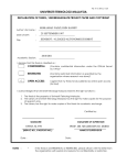
PSZ 19:16 (Pind. 1/07) UNIVERSITI TEKNOLOGI MALAYSIA UIOPRRRRRRRRRRRRRRRRRRRRRRRRRRRRRRRRRRRRRRRRRRRRRRRRR DECLARATION OF THESIS / UNDERGRADUATE PROJECT PAPER AND COPYRIGHT RRRRRRRRRRRRRRRRRRRROPRWEQ Author’s full name : NURUL SAZANA BINTI MOHD AZRI Date of birth : 22 APRIL 1989 Title : DEVELOPMENT OF A SMART PARCEL BOX USING RFID AND GSM TECHNOLOGY Academic Session : 2011/2012 I declare that this thesis is classified as : √ CONFIDENTIAL (Contains confidential information under the Official Secret Act 1972)* RESTRICTED (Contains restricted information as specified by the organisation where research was done)* OPEN ACCESS I agree that my thesis to be published as online open access (full text) I acknowledged that Universiti Teknologi Malaysia reserves the right as follows: 1. The thesis is the property of Universiti Teknologi Malaysia. 2. The Library of Universiti Teknologi Malaysia has the right to make copies for the purpose of research only. 3. The Library has the right to make copies of the thesis for academic exchange. Certified by : SIGNATURE 890422-12-5864 (NEW IC NO. /PASSPORT NO.) Date : 6 JULY 2012 NOTES : * SIGNATURE OF SUPERVISOR DR.MOHD HANIFF IBRAHIM NAME OF SUPERVISOR Date : 6 JULY 2012 If the thesis is CONFIDENTAL or RESTRICTED, please attach with the letter from the organization with period and reasons for confidentiality or restriction. “I hereby declare that I have read this thesis and in my opinion this report is sufficient in terms of scope and quality for the award of the degree of Bachelor of Electrical Engineering (Telecommunication).” Signature : …………………………. Name of Supervisor : Dr. Mohd Haniff Ibrahim Date : 6 July 2012 DEVELOPMENT OF A SMART PARCEL BOX USING RFID AND GSM TECHNOLOGY NURUL SAZANA BINTI MOHD AZRI A project report is submitted in fulfillment of the requirements for the award of the degree of Bachelor of Engineering (Electrical-Telecommunication) Faculty of Electrical Engineering Universiti Teknologi Malaysia JULY 2012 ii I declare that this report entitled “Development of A Smart Parcel Box Using RFID and GSM Technology” is the result of my own research except as cited in the references. The report has not been accepted for any degree and is not currently submitted in candidature of any other degree. Signature : ………………………………. Name : Nurul Sazana Binti Mohd Azri Date : 6 July 2012 iii Specially dedicated to my beloved family. Mohd Azri Abdullah Siti Rohani Ibrahim Mohd Afini Bin Mohd Azri Muhammad Zulfadli Arsy Bin Mohd Azri Nurfarahin Binti Mohd Azri Nurhafiza Binti Mohd Azri Indra Setia Bin Mohd Azri Muhammad Isham Bin Mohd Azri Nurul Asyiqin Binti Mohd Azri Mohd Irfan Bin Mohd Azri Thank you for the endless encouragements and supports. iv ACKNOWLEDGEMENT First and foremost, I would to thank Allah S.W.T that has given me His blessings and strength in order to complete my final year project successfully. I am very grateful that I am able to finish this project smoothly without any problems. Next, I would like to express my sincere appreciation and gratitude to my supervisor, Dr. Mohd Haniff Ibrahim for encouragement, guidance, critics, and supports given throughout completing this project and thesis. Special thanks to Encik Hamdan from Telekom Laboratory for his support and help to teach me new things related to my project. His ideas, views and tips are very useful for a beginner like me. Not forgotten to all my friends for their helps, moral supports and encouragement that they have given to me in order to complete this project. Last but not least, I would like to extend my sincere appreciation to my beloved family for all around support during the period of my study. Thank you. v ABSTRACT Package delivery service brings a lot of inconvenience to the customers especially when it comes to the delivering process. Package delivery should be settled with the presence of the house owner, so that they can receive the package safely without any problems. With this smart parcel box, the implementation of Radio Frequency Identification (RFID) and Global System for Mobile Communication (GSM) technology will bring more convenience to every customer especially during the office hour where they are too busy to pick up the packages. The owner will be notified regarding the arrival of the packages by an SMS as it will be sent through the GSM network. To implement this technology to the parcel box, we need to interface the RFID and GSM modem with a microcontroller. In order to achieve this, we need to develop the hardware for the parcel box and it will be controlled by the microcontroller which is programmed by using software called MikroC Pro for PIC. An SMS will be sent to the customer after the postman‟s RFID tag has been recognized as the authorized user. Thus, by receiving the SMS, the owner will know that the package have been safely arrived at the house. vi ABSTRAK Perkhidmatan penghantaran pakej membawa banyak kesulitan kepada pelanggan terutama ketika proses penghantaran. Penghantaran bungkusan perlu diselesaikan dengan kehadiran tuan rumah supaya pelanggan boleh menerima pakej dengan selamat tanpa sebarang masalah. Dengan kotak bungkusan yang pintar, pengunaan teknologi Pengenalpastian Frekuensi Radio (RFID) dan Sistem Global bagi teknologi Komunikasi Mudah Alih (GSM) akan memberi lebih banyak kesenangan kepada setiap pelanggan terutamanya semasa waktu pejabat, di mana mereka terlalu sibuk untuk mengambil pakej itu sendiri. Tuan rumah akan dimaklumkan mengenai ketibaan pakej dengan SMS yang akan dihantar melalui rangkaian GSM. Untuk melaksanakan teknologi ini pada kotak bungkusan, kita perlu perantara untuk RFID dan modem GSM dengan mikropengawal. Bagi mencapai matlamat ini, kita perlu memcipta perkakasan untuk kotak bungkusan itu dan ia akan dikawal oleh mikropengawal yang diprogramkan dengan menggunakan perisian yang dipanggil MikroC PRO for PIC. Satu SMS akan dihantar kepada pelanggan selepas tag RFID posmen telah dikenalpasti sebagai pengguna yang dibenarkan oleh sistem. Oleh itu, dengan menerima SMS tersebut, pemilik akan tahu bahawa pakej ini telah selamat tiba di rumah mereka. vii TABLE OF CONTENTS CHAPTER 1.0 2.0 TITLE PAGE DECLARATION ii DEDICATION iii ACKNOWLEDGEMENT iv ABSTRACT v ABSTRAK vi TABLE OF CONTENTS vii LIST OF TABLES x LIST OF FIGURES xi LIST OF ABBREVIATION xiii LIST OF APPENDICES xiv INTRODUCTION 1.1 Project Background 1 1.2 Problem Statement 2 1.3 Objectives 3 1.4 Scope of the Project 3 1.5 Thesis Outline 4 LITERATURE REVIEWS 2.1 Introduction 6 viii 2.2 RFID Technology 2.2.1 RFID Tags 9 2.2.2 RFID Reader: IDR-232 10 2.3 GSM Technology 2.3.1 Introduction 12 2.3.2 GSM Modem: MOD 9001D RS232 13 GSM/GPRS Modem 2.4 Short Messaging Service (SMS) 15 2.5 Microcontroller 2.5.1 Introduction 17 2.5.2 Basic Components 17 2.5.3 Advantages and Disadvantages of 18 Microcontroller 2.5.4 PIC Microcontroller: PIC16F877A 3.0 19 METHODOLOGY AND APPROACH 3.1 Introduction 22 3.2 Work Schedule of the Project 22 3.3 Project Planning 24 3.4 Project Block Diagram 26 3.5 Project Description 4.0 3.5.1 Hardware Development 28 3.5.2 Software Development 29 3.5.3 Programming Tools: MikroC PRO for PIC 30 3.5.4 PIC Programmer 32 RESULTS AND DISCUSSIONS 4.1 Introduction 35 4.2 Project Hardware 4.2.1 System Testing on Main Function 38 ix 4.2.2 System Testing on Parcel Box 5.0 39 CONCLUSIONS 5.1 Conclusion 41 5.2 Future Recommendations 42 REFERENCES 44-45 APPENDIX 46-53 x LIST OF TABLES TABLE NO. TITLE PAGE 2.1 Frequency Range of RFID 8 2.2 Timeline of the development of GSM 13 3.1 Work Schedule for FYP 1 23 3.2 Work Schedule for FYP 1 23 \ xi LIST OF FIGURES FIGURE NO. TITLE PAGE 2.1 MOD 9001D GSM/GPRS Modem 15 2.2 PIC16F877A by Cytron Technologies 20 2.3 PIC16F877A Pin Diagram 21 3.1 Overall Project Planning 25 3.2 Block Diagram of the Project 26 3.3 SK40C Enhanced 40 pins PIC with 20MHz Crystal Oscillator 29 3.4 Programming Work Flow 30 3.5 MikroC PRO for PIC 32 3.6 USB ICSP PIC Programmer UIC00B 33 3.7 PICkit 2 Programmer 34 4.1 Programming Flow Chart 36 4.2 Overall Project‟s Hardware in Standby Mode 37 4.3(a) Authorized User when tagged near the reader 38 4.3(b) SMS received upon ID card tagged 38 4.4(a) Authorized User detected by the system 39 xii 4.4(b) Green LED turned ON 39 4.5(a) Unknown User detected by the system 40 4.5(b) Red LED turned ON 40 xiii LIST OF ABBREVIATION RFID Radio Frequency Identification GSM Global System for Mobile Communication SMS Short Messaging Service USART Universal Synchronous Asynchronous Receiver Transmitter LF Low Frequency HF High Frequency UHF Ultrahigh Frequency PIC Peripheral Interface Controllers VLSI Very Large Scale Integrated IC Integrated Circuit xiv LIST OF APPENDICES APPENDIX I TITLE PIC16F877A Datasheet PAGE 46 1 CHAPTER 1 INTRODUCTION 1.1 Project Background Normally in Malaysia, for a delivering process we will use trusted courier company or delivery services such as Pos Malaysia, GD Express, DHL, Nationwide Express and etc. For the delivering process, the postman will send the packages to customer‟s house directly. For a certain delivery such as mails or newsletter, the postman will drop it inside the parcel box. Somehow, not all packages can be directly dropped into the parcel box especially big packages or important packages. This project is an improvement for a parcel box by using the RFID technology. We will use the SMS that will be sent through a GSM network to acknowledge the customers regarding the arrivals of package delivery. The uses of RFID and GSM technology in this project are to help the user to have a flexible and user-friendly parcel box system at their house. 2 To implement both RFID and GSM technology to the parcel box, we need to interface the RFID and GSM modem with a microcontroller. In order to achieve this, we need to develop the hardware for the parcel box and a system that controlled by the microcontroller which is programmed by using software called MikroC Pro for PIC. An SMS will be sent to the customer after the postman‟s RFID tag has been recognized as the authorized user. Thus, by receiving the SMS, the owner will know that the package have been safely arrived at the house. 1.2 Problem Statement Nowadays in Malaysia, people always got problems with big package delivery even though they have parcel box at their house. Normally, postman will send the packages directly to the customer‟s house. Somehow, courier services companies have their own policy which they need to ensure the package were sent safely and satisfy their customer needs. The problem occurs when the owner are not available when the postman do their routine to deliver the packages at customer‟s home. When such problem occurred, the postman in charge will leave some notes or make phone calls to inform the owner to pick the packages at post office or main office. 3 1.3 Objectives The main objective of this project is successfully come out with a smart parcel box using RFID and GSM technology controlled by a PIC microcontroller which is programmed using MikroC PRO for PIC software. The system should be able to send SMS to the customer‟s mobile phone when the RFID tag is detected by the RFID reader. Following are the specific objectives that are needed to achieve the main goal sequentially. i. To interface the RFID with PIC microcontroller ii. To interface GSM with PIC microcontroller iii. To successfully develop the smart parcel box with the implementation both RFID and GSM system. 1.4 Scope of the Project This project emphasizes more on how to implement and develop a smart parcel box using RFID and GSM, controlled by using a microcontroller. The scopes of this project are: i. Literature review on hardware and software used in this project. ii. Designing hardware for smart parcel box. iii. Programming which will be written in C language and stimulated using mikroC PRO for PIC software. 4 iv. Create interface between RFID and GSM modem using PIC microcontroller. v. 1.5 Develop SMS sending process via GSM modem. Thesis Outline In this thesis, there are five chapters which will briefly explain all the efforts and flows in completing this project. Chapter 1 introduces the background knowledge of the project, explains work scope of the project, for instance, problem statements, objectives and the scope of the project has been briefly defined in this chapter. Chapter 2 explains the basic knowledge of RFID and GSM technology and also reviews and related information used to develop smart parcel box such as microcontroller and the software used in this project. Chapter 3 states the methodology taken to complete this project successfully with a given period of time. In this chapter also will give a details work schedule in terms of Gantt chart for FYP 1 and FYP 2, project planning, project block diagram and the brief descriptions for this project. 5 Chapter 4 implies the results obtained from the system testing and troubleshooting in order to achieve the overall objectives required to complete this project. After gone through all the process and successfully achieved all the objectives as stated in the earlier chapter, the overall project can be conclude as explains in chapter 5. Future recommendation for this project is included as well for future works and further enhancement. 6 CHAPTER 2 LITERATURE REVIEW 2.1 Introduction This chapter will briefly explain about the basic concept of Radio Frequency Identification (RFID) technology. Basically, RFID system consists of RFID reader and tags. Moreover, in this chapter also will discuss more on Global System for Mobile Communication (GSM) technology, Short Messaging Service (SMS) and microcontroller. 2.2 RFID Technology Up until now, radio frequency identification (RFID) has been rapidly growing technology which is a very cost-effective technology and commercially used in practical applications such as access management, smart cards, logistics, tracking of persons and animals, asset tracking, manufacturing, retailing, payment system, and also security. 7 RFID is an acronym for radio frequency identification, which is a wireless communication technology that is used to uniquely identify tagged objects or people [1]. RFID also can be describes as a system of identification that uses radio frequency or magnetic field variations to communicate. Frequency refers to the size of the radio waves used to communicate between the RFID systems components. It is generally safe to assume that a higher frequency equates to a faster data transfer rate and longer read ranges, but also more sensitivity to environmental factors such as liquid and metal that can interfere with radio waves [2]. The RFID system currently operates in three main range of frequency which are low frequency (LF), high frequency (HF) and ultra-high frequency (UHF). This frequency range only affects the speed of the system, accuracy and range. Somehow, this frequency range does not affect the operation of the components. Table 2.1 shows the frequency range of RFID and its applications. 8 Table 2.1: RFID Frequencies [2] Frequency Operating Description Band Range 125 kHz to 134 kHz Low Frequency Below 0.5 meters 13.56 MHz High Frequency Below 1 meters 860 MHz to 930MHz 2.4GHz Ultrahigh Frequency (UHF) Microwave 3 meters 1 meters Applications • Access control • Animal tracking • Vehicle immobilizers • Product authentication • POS applications • Smart Cards • Smart shelve tags for item level tracking • Library Books • Airline baggage • Maintenance data logging • Pallet tracking • Carton tracking • Electronic toll collection • Parking lot access • Airline baggage • Electronic toll collection Benefits Drawbacks Works well around water and metal products. Short read range and slower read rates Low cost of tags Higher read rate than LF EPC standard built around this frequency Does not work well around items of high water or metal content Most expensive Fastest read rates 9 2.2.1 RFID tags An RFID tag is a device that can automatically transmit and receive signal from RFID reader using radio waves. The most basic function of an RFID tag is to store and transmit data to the reader or interrogator. A tag or sometimes called as transponder is made up of the microchip that stores the data, an antenna, and a carrier to which the chip and antenna are mounted [3]. They can be uniquely identified by the reader or host pair and, when applied or fastened to an object or a person, that object or person can be tracked and identified wirelessly [1]. Mostly for the RFID tags will at least contain two parts, one is an integrated circuit(IC) or a tiny semiconductor chip for storing and processing information, modulating and demodulating a radio frequency (RF) signal, and other specialized functions. Another part of RFID tags is miniaturized antenna, which is use for receiving and transmitting the signal. This RFID tags can be classified into two categories, it can be either active or passive RFID tags. (i) Passive tags For passive RFID tags, it does not contain a battery but can draw their own power from the reader (interrogator). This interrogator transmits a low power radio 10 signal through its antenna to the tag. Thus, in turn the tag will receives it through its own antenna to power the integrated circuit (chip). The tag will briefly converse with the reader for verification and the exchange of data. As a result, passive tags can transmit information over shorter distances (typically 10 feet or less) than active tags. They have a smaller memory capacity and are considerably lower in cost making them ideal for tracking lower cost items [3]. (ii) Active tags Active RFID tags are battery powered which can broadcast a signal to the reader and can transmit over the greatest distances (100+ feet). Typically they can cost more compare to passive RFID tags and are used to track high value goods like vehicles and large containers of goods. Shipboard containers are a good example of an active RFID tag application [3]. 2.2.2 RFID reader: IDR-232 A reader typically contains a radio frequency module (transmitter and receiver), control unit and a coupling element to the transponder. In addition, many readers are fitted with an additional interface (RS 232, RS 485, etc.) to enable them to forward the data received to another system (PC, robot control system, etc.) [7]. 11 IDR-232 RFID reader is a device that is used to interrogate an RFID tag. The reader has an antenna that emits radio waves. As interrogator or transceiver to activate the RFID tag, this RFID reader will receive information from the tag and transmit the information to the database (personal computer) via radio waves. A number of factors can affect the distance at which a tag can be read (the read range). The frequency used for identification, the antenna gain, the orientation and polarization of the reader antenna and the transponder antenna, as well as the placement of the tag on the object to be identified will all have an impact on the RFID system‟s read range. IDR-232 is plug and play RFID reader. It has been designed with capabilities and features of [14]: 2cm reading range and 0.1s response time. 125 KHz operating frequency. 9600 baud RS232 serial interface (output only) to PC. Low cost solution for reading passive RFID transponder tags. Integrated RFID reader, antenna, LED, power cable and data cable. Fully operation with 5VDC power supply. Buzzer as sound indication of activity. Bi-color LED for visual indication of activity. Use standard RS232 serial cable (female) for serial connection with PC or laptop. PS2 as power source from desktop PC. 12 IDR-232 RFID reader can be either connected to PC or microcontroller as part of embedded system. This RFID reader fully working with the passive RFID tag and can be applied in various area such as security system, car parking, office, hypermarket for item pricing, student projects etc. 2.3 GSM technology 2.3.1 Introduction Global System for Mobile communication (GSM) is a globally accepted standard for digital cellular communication. GSM is the name of a standardization group that was established in 1982 in an effort to create a common European mobile telephone standard that would formulate specifications for a pan-European mobile cellular radio system, with operating frequency at 900 MHz. Today over 400 million people worldwide use GSM mobile phones to communicate with each other, via voice and short-messageservice (SMS) text [4]. Originally, GSM stood for „Groupe Spécial Mobile‟, named after the study group that created it, the European Telecommunications Standards Institute (ETSI) which developed a standard set to describe technologies for second generation (2G) digital cellular networks. The acronym was later changed to „Global System for Mobile communications‟. This transition as well is one of the key aspects of GSM history, which elaborated subsequently in table 2.2. 13 Table 2.2: Timeline of the development of GSM [5] Year Events 1982 CEPT establishes a GSM group in order to develop the standards for a pan-European cellular mobile system 1985 Adoption of a list of recommendations to be generated by the group 1986 Field tests were performed in order to test the different radio techniques proposed for the air interface 1987 TDMA is chosen as access method (in fact, it will be used with FDMA) Initial Memorandum of Understanding signed by the telecommunication operators (representing 12 countries) 1988 Validation of the GSM system 1989 The responsibility of the GSM specifications is passed to the ETSI 1990 Appearance of the phase I of the GSM specifications 1991 Set date for the „official‟ commercial launch of the GSM service in Europe 1992 Actual launch of commercial service, and enlargement of the countries that signed the GSM – MoU > Coverage of Larger cities / airports 1993 Coverage of main roads GSM services start outside Europe 1995 Phase II of the GSM specifications Coverage of rural areas 2.3.2 GSM Modem: MOD 9001D RS232 GSM/GPRS Modem GSM modem is a wireless modem that works with GSM wireless network, which used the radio waves interface to send and receive data. This GSM modem needed SIM (Subscriber Identity Module) card in order to function. Moreover, to control the function of GSM modem, AT command is used. Basically, AT commands is a 14 standard command for GSM modem, which will allow it to perform various commands such as: Read, write and delete SMS Send SMS Monitor the signal strength Monitor the charging status and charge level of the battery Check on the credit balance. MOD 9001D RS232 GSM/GPRS Modem used in this project is one of Sky Microwave Co. Ltd product. The GSM Modem can only be used after being connected to antenna and has a valid SIM card inserted inside the SIM card holder. This type of GSM modem supports GSM Tri band (900/1800/1900 MHz) and have better signal quality. The MOD 9001D GSM/GPRS Modem mostly fits the need of data transfer, with SMS data communication, GPRS data navigation, Circuit Switch / Data Connectivity, TCP/IP protocol. The MOD 9001D GSM/GPRS Modem with small size, which fits both embedded application and external peripheral equipment. The AT command set and RS232 interface will offer easy data connection without any extra circuit control [15]. 15 Figure 2.1: MOD 9001D GSM/GPRS Modem [15] 2.4 Short Messaging Service (SMS) Short Message Service (SMS) is a globally accepted service using GSM network and widely used in mobile phones. It is a text messaging service component of phone, web, or mobile communication systems. It is used the standardized communications protocols that allow the exchange (sending and receiving) of short text messages between fixed line or mobile phone devices. Short Message System (SMS) messaging provides a convenient way to communicate between mobile phone devices. The sending and receiving text message between mobile phones devices are basically through Global System for Mobile Communications (GSM) network. The use of SMS on modern handsets was originated from radio telegraphy in radio memo pagers, which used the standardized phone protocols and later defined as part of the Global System for Mobile Communications (GSM) series of standards in 1985. As a means, the process sending messages to and from GSM mobile handsets can be up to 160 characters. Ever since then, support for the service has expanded to include other mobile technologies such as ANSI CDMA networks and Digital AMPS, as well as satellite and landline networks. 16 In addition to being a great way of communicating people, SMS can be a useful way for applications to exchange simple messages between devices. SMS works across most cellular service providers, which does not require a direct connection between devices, the infrastructure for the system is already in place. 2.5 Microcontroller For various applications microprocessors have been widely used since they were invented. However, there are several limitations in the initial microprocessor designs which lead to the development of microcontrollers: (i) External memory chips are needed to hold programs and data because the early microprocessors did not have on-chip memory. (ii) Glue logic (such as address decoder and buffer chips) is required to interface with the memory chips. (iii) Peripheral chips are needed to interface with 110 devices. Because of these limitations suffered by microprocessors, a product designed with it cannot be made as compact as might be desirable. The development of microcontrollers has not only overcome most of these problems but also enabled the design of many low-cost microprocessor-based products. 17 2.5.1 Definitions A microcontroller is a computer-on-a-chip, or, known as a single-chip computer. The term “Micro” suggests that the device is small, and the term for “controller” is referred as the device might be used to control objects, processes, or events. Another term to describe a microcontroller is embedded controller, because the microcontroller and its support circuits are often built into, or embedded in, the devices they control [8]. 2.5.2 Basic Components Microcontroller is said to be similar as microprocessor inside a personal computer, which both microprocessors and microcontrollers contain a central processing unit (CPU). The CPU executes instructions that perform the basic logic, math, and datamoving functions of a computer. The requirements of a microprocessor needed for a complete computer are the memory for data storage and programs, and input/output (I/O) interface for connecting external devices like keyboards and displays. In contrast for a microcontroller, it is known as a single-chip computer because it contains memory and I/O interfaces in addition to the CPU. Because the amount of memory and interfaces that can fit on a single chip is limited, microcontrollers tend to be used in smaller systems that require little more than the microcontroller and a few support components. 18 A microcontroller, or MCU, is a computer implemented on a single very large scale integrated (VLSI) circuit. In addition to those components contained in a microprocessor, an MCU also contains some of the following peripheral components [6]: Memory Timers, including event counting, input capture, output compare, real-time interrupt, and watchdog timer Pulse-width modulation (PWM) Analog-to-digital converter (ADC) Digital-to-analog converter (DAC) Parallel I/O interface Asynchronous serial communication interface (UART) Synchronous serial communication interfaces (SPI, 12C, and CAN) Direct memory access (DMA) controller Memory component interface circuitry Software debug support hardware 2.5.3 Advantages and Disadvantages of Microcontroller Since their introduction, MCUs have been used in almost every application that requires certain amount of intelligence. The invention of microcontrollers has its pros and cons. The main advantages of microcontrollers are given as follows: Microcontrollers act as a microcomputer without any digital parts. 19 As the higher integration inside microcontroller reduce cost and size of the system. Usage of microcontroller is simple, easy for troubleshoot and system maintaining. Most of the pins are programmable by the user for performing different functions. Easily interface additional RAM, ROM, I/O ports. Low time required for performing operations. The disadvantages for a microcontroller are: In contrast to microprocessors, microcontrollers have more complex architecture. Only limited number of executions can be performed simultaneously. Commonly used in micro-equipments. High power devices cannot be interface directly. 2.5.4 PIC Microcontroller: PIC16F877A PIC stands for Peripheral Interface Controllers (PIC). PIC microcontroller is a family of Harvard architecture microcontrollers made by Microchip Technology. PIC microcontroller which know as a single-chip microcomputer, well suited for control and automation of machine and process in electronics and have more attractive features that suitable for wide range applications. PIC is popular due to their wide range ability, availability of low cost or free development tools and serial programming capability. 20 PIC16F877A is a small integrated circuit (IC) available with 40 pins package. This PIC is a powerful and very easy-to-program CMOS FLASH-based 8-bit microcontroller packs introduced by Microchip Technology. The PIC16F877A features 256 bytes of EEPROM data memory, self programming, an ICD, 2 Comparators, 8 channels of 10-bit Analog-to-Digital (A/D) converter, 2 capture/compare/PWM functions, the synchronous serial port can be configured as either 3-wire Serial Peripheral Interface (SPI™) or the 2-wire InterIntegrated Circuit (I²C™) bus and a Universal Asynchronous Receiver Transmitter (USART). All of these features make it ideal for more advanced level A/D applications in automotive, industrial, appliances and consumer applications [11]. Figure 2.2: PIC16F877A by Cytron Technologies [12] Figure 2.3 shows the pin diagram for PIC16F877A. For more details about the PIC microcontroller, please refer to the datasheet given. The datasheet can be found in Appendix I. 21 Figure 2.3: PIC16F877A Pin Diagram [13] 22 CHAPTER 3 METHODOLOGY AND APPROACH 3.1 Introduction This chapter discusses in detail the methodologies that have been used in this project. It will consist of project planning, project block diagram and project description. 3.2 Work Schedule of the Project Table 3.1 and 3.2 shows the overall action plan of the project for both semesters. 23 Table 3.1: Work Schedule for FYP 1 No. Activity 1 FYP Briefing Project Suggestion/Briefing Literature Review Submission of Project Proposal Preparation for Project Presentation(Seminar) FYP 1 Seminar Project Draft(Report) 2 3 4 5 6 7 1 Week 2 3 4 5 6 7 8 9 10 11 12 13 14 15 Table 3.2: Work Schedule for FYP 2 No. 1 2 3 4 5 6 7 8 9 Activity Literature Review Building Prototype Designing & Programming Simulation Develop a prototype Troubleshooting & Enhancement Modeling and develop hardware Project Presentation (Seminar) Project Draft(Thesis) Week 1 2 3 4 5 6 7 8 9 10 11 12 13 14 15 16 17 18 19 20 24 3.3 Project Planning In order to achieve the objective of the project, the first step need to consider is a comprehensive reading and literature review on RFID system, GSM system, SMS system and microcontroller. Next, the most important step need to be considered is the ways connect and create the interface between the RFID and GSM system with the microcontroller. By interfacing the systems with the microcontroller, we will able to communicate the system by using a programming in C language. The software were used for the programming is MikroC for Pro version 4.60. After that, the process is continues with designing and developing the smart parcel box using RFID and GSM technology. 25 Literature Review on RFID system, GSM modem and microcontroller Designing and programming to interface GSM modem with PIC microcontroller Study on the equipments (hardware) Simulation stage Study on the software were used for programming (Micro-C Pro) Study on LED blinking, LCD display and button (push button): Designing the system and programming using Micro-C Pro Designing and programming to interface RFID system with PIC microcontroller Development of prototype System Testing: Troubleshooting and Enhancement Modeling & developing the hardware Final Presentation and Thesis Figure 3.1: Overall Project Planning 26 3.4 Project Block Diagram This project is an implementation of smart parcel box system using RFID and GSM technology in which the user will be notified regarding the arrival of new package to their home. Figure 3.2 below illustrates the block diagram of the project. As the RFID tag detected by the RFID reader, the users will be either recognize as authorized user or unknown user. The LCD will display welcome notes and the ID number of the users. There are two LED were used in this project which are red and green. Red LED indicates the parcel box in standby mode or the parcel box is close. Whereas the green LED indicates the parcel box has open when the authorized user‟s tag has been detected. GSM modem will send an SMS to user‟s phone as a notification of the package arrivals. By creating interfaces between all this equipments, source code is needed for the programming in order to control the system by using PIC microcontroller (PIC16F877A). 27 Figure 3.2: Block Diagram of the Project 3.5 Project Description The smart parcel box implemented using RFID and GSM technology is designed to ease the customers. This project will help the customers to have fast information regarding the new package arrivals at their houses. Other than that, it will help the postman to have a reliable, well-organized and secure system for package delivery. This project consists both hardware and software implementation. In hardware development, passive RFID tag will be used by the postman. The RFID reader will be placed near the parcel box where postman need to tag his card near the RFID reader. The tag will have its own unique identification number which will differentiate it with others. The user information will be programmed and burned inside 28 the PIC16F877A. PIC16F877A will act as the brain of the system where it will control all the activities. This PIC microcontroller will be interfaced between the RFID and GSM modem as well as the LCD and other components. For the software development, the software used is for the programming is MikroC PRO for PIC. This software is used to program the PIC16F877A, where the programming will be written using C language. The PIC microcontroller will control the SMS sending process to the customer‟s phone. Other than that, when the postman‟s tag is tagged near the RFID reader, the system will store the unique serial identification number and it will be recognize as authorized user in the microcontroller database. As the tag has been recognized by the system itself, the PIC will ask the GSM modem to automatically send an SMS as a notification to the customer to inform about the new package arrivals. 3.5.1 Hardware Development In this project, Cytron Technologies SK40C was used to ease the hardware implementation for the overall system. The pins of SK40C is plugged and soldered onto the donut board to access the I/O (Input/Output). The input power supply by the adapter to the board is 12V. Since, the board consists of a voltage regulator circuit which will regulate the input power supply down to 5V. Also, a 20MHz crystal oscillator has been used in this board with the starter kit to allow an electrical oscillator with a precise frequency. This frequency is commonly used in order to provide stable clock signal for digital integrated circuit (IC) and it will stabilize the frequencies for radio transmitters and receivers. 29 Figure 3.3: SK40C Enhanced 40 pins PIC with 20MHz Crystal Oscillator In this project, it requires two serial connection ports using RS232 for both RFID and GSM modem. Since PIC16F877A only has one external serial connection (USART), there need to be one external circuit of MAX232 to provide enough two serial connection ports for RFID and GSM. This two serial connection ports are needed in order to interface both RFID and GSM with the PIC16F877A. This circuit will consists of one MAX232, two DB9 connector and four 1uF capacitors which used to support the serial connection. The PS2 connector also connected to the personal computer to provide 5V power supply for RFID reader. This connection terminated at port C of PIC16F877A. Two additional LEDs been added to the circuit which indicates the parcel box lid. Green LED for open parcel box lid and red LED for closing the parcel box lid. Both LEDs were terminated at port B of the PIC16F877A. 30 3.5.2 Software Development Figure 3.4 shows the programming work flow of the project. This work flows explains step by step of the programming process from program writing up until the burning process inside the PIC16F877A. Run the prototype for system testing Build and simulate the source code Develop Prototype Write programming using MikroC PRO for PIC Burn the programming into PIC16F877A Figure 3.4: Programming Work Flow 3.5.3 Programming Tools: MikroC PRO for PIC MikroC PRO for PIC is a full-featured ANSI C compiler for PIC devices from Microchip®. It is the best solution for developing code for PIC devices. It features intuitive IDE, powerful compiler with advanced optimizations, lots of hardware and software libraries, and additional tools [9]. 31 MikroC PRO for PIC uses C language for programming. C language is a high level programming language which can be used to develop source code either for simple program or complex applications. Several features of MikroC PRO for PIC which will allow quickly develop and deploy complex applications [9]: Write C source code using the built-in Code Editor (Code and Parameter Assistants, Code Folding, Syntax Highlighting, Auto Correct, Code Templates, and more.) Use included mikroC PRO for PIC libraries to dramatically speed up the development: data acquisition, memory, displays, conversions, communication etc. Monitor program structure, variables, and functions in the Code Explorer. Generate commented, human-readable assembly, and standard HEX compatible with all programmers. Use the integrated mikroICD (In-Circuit Debugger) Real-Time debugging tool to monitor program execution on the hardware level. Inspect program flow and debug executable logic with the integrated Software Simulator. Get detailed reports and graphs: RAM and ROM map, code statistics, assembly listing, calling tree, and more. MikroC PRO for PIC provides plenty of examples to expand, develop, and use as building bricks for projects. Figure 3.5 shows MikroC PRO for PIC software, which is used in this project for programming. 32 Figure 3.5: MikroC PRO for PIC 3.5.4 PIC Programmer The UIC00B PIC Programmer is design to program PIC microcontroller which includes most of the PIC family. In this project, the PIC Programmer is used to program the programming written using MikroC PRO for PIC inside the PIC16F877A as shown in Figure 3.6. This PIC Programmer comes together with the PICkit 2 Programmer, which will enable it to program the programming inside the PIC16F877A through this software as shown in Figure 3.7. 33 This also allow user to quickly program and debug the source code while the target PIC is on the development board. Since USB port is commonly available and widely used on Laptop and Desktop PC, UIC00B is designed to be plug and play with USB connection. This programmer obtained its power directly from USB connection, thus NO external power supply is required, making it a truly portable programmer. This programmer is ideal for field and general usage. UIC00B offers reliable, high speed programming and free windows interface software [10]. Figure 3.6: USB ICSP PIC Programmer UIC00B 34 Figure 3.7: PICkit 2 Programmer 35 CHAPTER 4 RESULTS AND DISCUSSION 4.1 Introduction After developing the hardware and complete the programming for the smart parcel box, the system needs to undergo testing stage to make sure that the system functioning well for the overall process. The programming writes in MikroC PRO for PIC need to be stimulated and then burn inside the microcontroller and tested using the hardware. Figure 4.1 illustrates the programming flow chart of the project. This flow chart shows the process of the programming on how the parcel box‟s system operates. 36 RESET START LCD display welcome note Parcel box closed & red LED ON Scan RFID tag Authorized user? NO LCD display “Unknown User” YES LCD display user name and ID Generate and send SMS Parcel box opened & green LED ON Package dropped After 5 minutes, parcel box closed & red LED ON Figure 4.1: Programming Flow Chart 37 4.2 Project Hardware The overall connection for the project hardware in standby mode is shown in Figure 4.2. In figure below, both red and green LEDs will indicate the parcel box whether it is opens or close. The red LED turned ON, which means the parcel box is close when the system in standby mode. Besides that, the RFID reader also in the standby mode, which clearly can be seen at the reader itself, the yellow light were appeared. In standby mode, the LCD displayed the welcome notes as “WELCOME” and “Tag Your ID Here”. Figure 4.2: Overall Project’s Hardware in Standby Mode 38 4.2.1 System Testing on Main Function Figure 4.3(a) shows when postman ID card tagged near the RFID reader, the LCD displayed “Authorized User”. The identification number for the ID card also will be displayed in the LCD. As shown in Figure 4.3(b), when the ID card is tag near the RFID reader, an SMS will be send to the user‟s phone as a notification for the new package arrivals at their home. Figure 4.3(a) Figure 4.3(b) Figure 4.3: (a) Authorized User when tagged near the reader (b) SMS received upon ID card tagged 39 4.2.2 System Testing on Parcel Box As shown in Figure 4.4(a), when the postman tags the ID card near the RFID reader, LCD will display the ID number and it will recognized as “Authorized User”. The system has detected the identification number of the postman‟s tag the same as stored in the database From Figure 4.4(b), the green LED is turned ON, which indicates that the parcel box has opened for user that have been recognized by the system only. Figure 4.4(a) Figure 4.4(b) Figure 4.4: (a) Authorized User detected by the system (b) Green LED turned ON In Figure 4.5(a), when other ID card tags near the RFID reader, LCD displayed “Unknown User” since the system did not recognize the ID card. There is no detail information of it stored inside the database. From Figure 4.5(b), the red LED is turned 40 ON, which indicates the parcel box will not open for a user that cannot be recognize by the system. Figure 4.5(a) Figure 4.5(b) Figure 4.5: (a) Unknown User detected by the system (b) Red LED turned ON 41 CHAPTER 5 CONCLUSION This chapter covers the overall conclusion and the future recommendations for enhancement in order to improve this project. 5.1 Conclusions The aim of this project is to develop a smart parcel box using RFID and GSM technology which will directly notified the customers regarding the arrival of new packages via SMS. Besides that, the system of this parcel box need to be created by interfacing the RFID and GSM modem with a microcontroller. This microcontroller will be programmed using software called MikroC PRO for PIC which enables the microcontroller to control both the RFID and GSM modem. This system should be able to send SMS to the customers when the RFID reader detects the RFID tag which contains the identification number (ID card) of the postman. 42 Generally, this project is a success and the objective of this project has been achieved based on the objectives stated above and the objective requirement stated in the earlier chapter. A complete functional and reliable system for a smart parcel box has been build and developed which was successfully tested. Throughout completing this project, lots of new knowledge gained regarding the hardware and software used in this project. The implementation of RFID technology can definitely help to reduce the hardships that have been through by the postman when delivering the package to the customer‟s house. Other than that, the implementation of GSM technology in this system will help informing the customers about the new package arrivals via SMS. Thus, this will provide a more reliable, convenient and userfriendly system with both implementation of RFID and GSM technology which created a smart parcel box. 5.2 Recommendations This system has been successfully developed and tested. As for future work, few improvements should be done to ensure that the system is practical enough to be applied for the community. However, several possible enhancements can be done to overcome its limitations. Although the project has met the objectives stated before, its performance still can be enhanced to make it more sophisticated system. To make the system more sophisticated, this smart parcel box system can be upgraded by increasing the security of the system. Instead of informing the customers regarding the arrivals of the new packages, the customers can decide whether to give 43 postman approvals to drop the package inside the parcel box or not. When postman tag their ID card near the RFID reader, an SMS will be send to the customer for permission to open the parcel box. At this stage, the customer needs to reply as soon as possible to give approval for the postman to drop the package. If the customer does not reply the message in 5 minutes, the parcel box will automatically close and the postman does not have any permission to drop the package inside it. With this application, the security of the system can be increase since the postman needs to have the permission first before dropping the package inside the parcel box. 44 REFERENCES 1. Hunt, V.D., Puglia, M. and Puglia A. 2007. RFID: A Guide to Radio Frequency Identification. United States of America: John Wiley & Sons, Inc., Publication. 2. Scan Source Europe Website: http://www.scansource.eu/en/technologyeducation-89.htm, Technology Education: RFID Frequencies, retrieved in December 2011 3. Scan Source Europe Website: http://www.scansource.eu/en/technologyeducation-89.htm, Technology Education: RFID Basics, retrieved in December 2011 4. Gayal, S., Manickam, S.A.V. Comparative analysis of GSM and CDMA technologies “A Security Perspective”. Network Security Solutions Ltd. Pune. 5. Scourias, J. 1997. Overview of the Global System for Mobile Communications. Link: http://www.shoshin.uwaterloo.ca/ ~jscouria /GSM/gsmreport.html. 6. Han-Way Huang. 2005. PIC Microcontroller: An Introduction to Software and Hardware Interfacing. United States of America: Thomson, Delmar Learning. 7. Klaus, F. (1999). RFID Handbook: Radio Frequency Identification Fundamentals and Applications, Germany: John Wiley & Sons LTD. 8. Axelson, J. 1997. The Microcontroller Idea Book: Circuits, Programs, & Applications featuring the 8052-BASIC Microcontroller. Madison, Wisconsin: Lakeview Research. 9. MikroElektronika, MikroC PRO for PIC: User Manual Version 1.1. April 2009. 10. Cytron Technologies. UIC00B USB ICSP PIC Programmer User's Manual. Malaysia, December 2011. 45 11. Microchip Technology Website, http//:www.microchip.com, retrieved in January 2012. 12. Cytron Technologies Website, http//:www.cytron.com.my, retrieved in January 2012. 13. Cytron Technologies. PR23 User’s Manual: Multifunction Mobile Robot. Malaysia, August 2008. 14. Cytron Technologies. Cytron RFID Reader IDR-232: Instructions Manual Version 1.1. Malaysia, March 2007. 15. Sky Microwave Co. Ltd. MOD 9001D RS232 GSM/GPRS Modem: User Manual. 2007. 16. Nur Syafiqah BintiAzmi (2011). Parking Payment System Using RFID and GSM. Skudai, Johor, Universiti Teknologi Malaysia. Degree Thesis. 17. Fadalia Dina Binti Dahlan (2011). Optical Counter for Car Parking System. Skudai, Johor, Universiti Teknologi Malaysia. Degree Thesis. 46 APPENDIX I PIC16F877A Datasheet 47 48 49 50 51 52 53