1
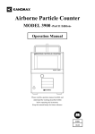
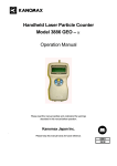
Handheld Laser Particle Counter
MODEL 3887
Operation Manual
Read this manual carefully and understand the warnings
described in this manual before operating the product.
Keep this manual handy for future reference.
06001
07. 12
Thank you for purchasing a product of Kanomax, Inc.
Please read this operation manual carefully and operate the
instrument appropriately by following the instructions given
in this manual.
Important Safety Information
Types and definitions of warning signs used in this operation manual are shown below.
Danger: To prevent serious injury or death
Warnings in this classification indicate danger that may result in serious
injury or death if not observed.
Caution: To prevent damage to the product.
Warnings in this classification indicate risks of damage to the product and
performance failure that affect the product warranty if not observed.
[Description of Symbols]
This symbol indicates a condition (including danger) that requires caution. The
subject of each caution is illustrated inside the triangle (e.g., high temperature
caution symbol shown on the left).
This symbol indicates prohibition. Do not take a prohibited action shown inside
or near this symbol (e.g., disassemble prohibiting symbol shown on the left).
This symbol indicates a mandatory action. A specific action is given near the
symbol.
This symbol indicates a warning of possible laser radiation.
i
Danger
○ Never disassemble or heat the battery pack,
or discard the battery pack in fire.
- The battery pack may explode.
Explosive
Handle
Properly
○ For AC power supply, do not use the AC adapter other than
the one supplied with the instrument.
- An inappropriate adapter may damage the instrument.
- It may generate heat and cause fire.
Prohibition
○ Never disassemble, modify or repair.
- This instrument uses a Class 3B laser diode as the light source.
Exposure to the laser may cause loss of eyesight and other injury.
Do Not Modify or
Disassemble
- Disassembly may cause short circuit and/or other failure.
○ Handle the instrument properly in accordance with the instructions
provided in this operation manual.
- Improper use may cause electric shock, fire hazard, and damage.
○ If abnormal noise, smell or smoke is observed, or if liquid has
entered the instrument, turn off the power immediately, remove the
batteries or pull out the plug.
- Failure to observe the above may cause electric shock, fire hazard or
damage.
Please contact your local distributor or Kanomax’s service center for
repair.
ii
Handle Properly
Caution
○ Do not use or keep the instrument in hot,
humid, or dusty environment.
- The instrument may not function properly
outside the specified temperature range.
Prohibited
Installation
- Exposure to direct sunlight may discolor or
deform the instrument.
○ Do not drop or hit the instrument.
- Dropping or hitting the instrument may
cause damage and malfunctioning.
Prohibition
+
○ Set batteries in the correct direction.
- Setting the batteries in the wrong direction may cause
leakage, leading to contamination of the instrument and
surroundings.
Insert
Properly
-
○ Do not wipe the instrument with a volatile solvent.
- The body may deform or deteriorate. Use soft dry cloth to remove stains.
If stains persist, soak the cloth in a neutral detergent and wipe the instrument
with a soft cloth.
Do not use volatile solvents such as thinner and benzine.
○ Do not use the instrument near equipment emitting high radiation
noise.
- The instrument may malfunction due to the noise.
○ Connect the AC adapter to a power source with minimum noise.
- The noise may cause malfunctioning.
iii
Prohibition
Handle
Properly
Caution
○ Pull out the plug when the instrument is not in use.
- Failure to observe the above may cause electrical shock, fire hazard,
and circuit damage.
○ If the instrument is not to be used for a long period,
the batteries must be removed from the battery compartment.
Do not leave spent batteries in the battery compartment.
- Failure to observe the above may cause battery leakage.
iv
Handle Properly
Table of Contents
1. Packing List ............................................................................................... 1
1.1 Standard Accessories ........................................................................................................... 1
1.2 Optional Accessories (Sold Separately) .............................................................................. 1
2. Description of Components....................................................................... 2
3. Precautions for Use ................................................................................... 4
4. Measurement Modes ................................................................................. 5
4-1 REPEAT Mode.................................................................................................................... 6
4-2 SINGLE Mode .................................................................................................................. 10
4-3 CONT Mode ..................................................................................................................... 12
4-4 CALC Mode ..................................................................................................................... 14
4-5 REMOTE Mode ................................................................................................................ 16
4-6 ISO>4 Mode ..................................................................................................................... 18
5. View Stored Data..................................................................................... 21
5-1 Viewing Stored Data on LPC Screen ............................................................................... 22
5-2 Printing Stored Data .......................................................................................................... 23
5-3 Delete Stored Data ............................................................................................................ 26
6. Useful Functions ..................................................................................... 27
6-1 Alarm ................................................................................................................................ 28
6-2 Changing Measurement Unit ............................................................................................ 29
6-3 Calendar Setting ................................................................................................................ 30
6-4 Communication Setting .................................................................................................... 31
6-5 Hotkey ............................................................................................................................... 32
6-6 Automatic Measurement Start ........................................................................................... 33
7. Error Messages ........................................................................................ 34
8. Low Battery Alarm .................................................................................. 35
9. Specifications .......................................................................................... 36
10. Troubleshooting ..................................................................................... 37
11. Warranty and After Service ................................................................... 38
12. Contact Information .............................................................................. 39
v
1. Packing List
Check all components when opening the package.
For purchasing optional accessories, please contact your local distributor.
1.1 Standard Accessories
Item
Filter,
Tube
AC Adaptor,
Power Cable
Ni-MH Batteries
Rapid Charger
Application
Software CD
Model
3887-03*1)
3887-01*2)
HR-3U
(or product of same
specification)
NC-NQR02
(or product of same
specification)
S388-70
Description
To clean the air flow path inside the instrument with clean
air.
To operate the instrument with AC power, especially for
continuous measurement.
To operate the instrument with battery power.
*The batteries cannot be charged by using the AC adapter.
The dedicated charger listed below must be used for
charging the batteries.
To recharge the Ni-MH batteries.
Charging time is approx. 240min.
For operations such as transferring the data stored in the
instrument memory to a computer, or controlling the
instrument by a computer.
*Operation Manual for Application Software is saved in the CD.
RS232C Cable
Stand
3887-08
Isokinetic Probe
Traceability
Certificate
To connect the instrument with a computer.
To stabilize the instrument for measurement.
To be connected to the inlet to match the measurement
condition with the sampling air.
Calibration certificate.
1.2 Optional Accessories (Sold Separately)
Item
Printer
Printer Cable
Carrying Case
Tripod
Model
DPU-H245
3887-07
3887-02
Description
To directly print the measured data from the instrument.
To connect the instrument with a printer.
To store the instrument.
To stabilize the instrument for measurement.
*1) Model 3887-03 includes a filter and a connection tube.
*2) Model 3887-01 does not include an extension power cable.
1
2. Description of Components
Inlet
2.83L/min suction volume
START/STOP Key
To start/stop sampling
ENTER Key
To execute a menu and
enter a setting
PREV Key
To switch the display
screen
POWER Key
To turn ON/OFF the
power.
▲ ▼ Keys
To select a menu and change
a setting.
Communication Port
DC Jack
To communicate with a
computer or printer.
To supply power with a
dedicated AC adapter.
2
Battery Compartment
Use four (4) AA rechargeable
batteries or alkaline batteries.
Operating hours by battery power
are only ensured when using the
supplied Ni-MH batteries.
3
3. Precautions for Use
The following precautions must be taken when using the instrument.
● Sampling
There are possibilities of particle deposit/rescattering when sampling is performed by using a
tube connected to the inlet. It is recommended that sampling is performed without using the tube.
However, if a tube is required for sampling, the tube recommend below must be used.
● Sampling Tube
Recommended Sampling Tube:
TYGON Inner Diameter 4.3mm × Outer Diameter 7.5mm: Product or Norton
This product can be purchased from dealers of physical and chemical equipment, as well as
through our sales offices.
● Power
The instrument can be powered by AA batteries or AC power.
● AC Power
For AC-powered operation, the dedicated AC adapter supplied with the instrument must be used.
The AC adapter accommodates voltage of AC 86-264V 50/60Hz, however, the connection plug is
dedicated to AC 100V.
● AA Batteries
In addition to the supplied AA rechargeable batteries (Ni-MH 1.2V 1600mA), alkali batteries can
be used as well.
Maximum continuous operating hours:
- When using alkali batteries
: 1 hour
- When using the supplied rechargeable batteries
: 3 hours
The above continuous operating hours are subject to change due to operational conditions such as
ambient condition, or use of the sampling tube.
● Caution for Extremely Long Measurement Periods
The instrument is unsuitable for continuous measurements for a prolonged period. It may hasten
deterioration of the light source and inner pump, and require maintenance in a shorter interval.
● For Prolonged Measurements
Note that the data will not be saved if the power is cut during a measurement.
Make sure to prevent running out of batteries or power cut of AC power.
● Sampling Environment
The instrument is designed for use in clean rooms or clean environments where the concentration
is below the maximum measurable concentration of 2,000,000 particles/cf. Using the instrument
in a high temperature/humidity environment or in an environment with high particle
concentration may cause damage to the instrument or shorten the maintenance interval.
4
4. Measurement Modes
The instrument is equipped with six (6) measurement modes.
● REPEAT Mode (Suitable for repeated measurement at a same location.)
Measurement of a certain sampling period and interval can be repeated from twice to infinite
number of times. When storing the measurement data, the maximum number of measurements is
10,000 times.
● SINGLE Mode (Single measurement which stops when set sampling time has elapsed.)
Measurement stops automatically when set sampling time has elapsed.
● CONT (Continuous) Mode (Suitable for measurement of random time)
Measurement is stopped manually.
● CALC (Calculation) Mode (Processes results of repeated measurements.)
Measurement is repeated as same as the REPEAT Mode, and based on the results obtained from
the repeated measurements, average, maximum, minimum, and standard deviation are
calculated and displayed.
When storing the data in the instrument in CALC mode, only the calculation result; average,
maximum, minimum, and standard deviation will be stored, and detail data from the repeated
measurements will NOT be stored.
<Caution>
Storing the data in CALC mode requires memory 4 times larger than that of modes such as
REPEAT, SINGLE and CONT Modes. When all data is taken in CALC Mode, maximum 2,500
data records can be stored.
● ISO>4 Mode (Suitable for cleanliness assessment of ISO Class 5 to 9)
This mode is suitable for cleanliness assessment in accordance with ISO14644-1, 2 or JIS B9920.
The result is displayed by calculating the average, standard deviation and 95% UCL
automatically from the sampled data and number of sampling times.
● REMOTE Mode (Externally controlled measurement)
Measurement is controlled externally by using the software supplied with the instrument.
5
4-1 REPEAT Mode
Setup procedure is shown below.
(Character positions may not correspond to the actual screen.)
Power Up
Measurement Setting Screen
<MENU>
1.MEASURE MODE
2.DATA PROCESSING
3.OPTIONS
Press ENTER key
< MEASURE MODE >
1.REPEAT
4.CALC
2.SINGLE
5.REMOTE
3.CONT
6.ISO>4
Press ENTER key
REPEAT
0.3/0.5/5.0um
LOC.021 STR:N BEEP:N
SAMPLE
01:00 2TIMES
INT 00:10:00
NO
Press ENTER key
SAMPLING
SAMPLE TIME
TOTAL TIME
00:01:00
00:12:00
OK
LOC.:
LOC number can be used for identifying room
numbers or measurements. Setting of this item
is not mandatory.
STR:
Used when storing data in the instrument. When
storing the data, select “Y” by using the ▲▼
key. Select “N” if you do not want to store the
data.
BEEP:
Alarm goes off when alarm level is exceeded.
SAMPLE:
Sets sampling time. Setting range is from 10 sec
to 99min 59sec.
TIMES:
Sets number of sampling times. Setting range is
from 1 to 99, or CONT (Repeats until storage
capacity is reached. Max. 10,000 times.)
INT:
Sets duration of one measurement cycle. Setting
range is from 10sec to 99min 59sec. Minimum
time is dependent on set sampling time.
Press ENTER key
REPEAT 30B
20:32
WAIT
0.3 0.00E+0/m3
0.5 0.00E+0/m3
00/02
5.0 0.00E+0/m3
Setting of every item is not mandatory.
For example, you can change only the LOC
number and press the START/STOP key, and the
display will switch to a measurement standby
screen.
6
REPEAT 30B
20:32
READY 0.3 0.00E+0/m3
0.5 0.00E+0/m3
00/02
5.0 0.00E+0/m3
Press START/STOP key
REPEAT 30B
20:32
RUN
0.3 0.00E+0/m3
00:59
0.5 0.00E+0/m3
01/02
5.0 0.00E+0/m3
The measurement unit can be changed by using the
▲▼ key.
CNT : Integrated value
/m3 : Number of particles per one cubic meter.
/cf
: Number of particles per 28.3L.
WAIT… 30B
20:32
0.3 0.00E+0/m3
20:42
0.5 0.00E+0/m3
01/02
5.0 0.00E+0/m3
[Display of Optional Specification]
REPEAT 30B
20:32
WAIT
0.3 0.00E+0/m3
0.5 0.00E+0/m3
00/02
1.0 0.00E+0/m3
REPEAT 30B
20:32
RUN
0.3 0.00E+0/m3
00:59
0.5 0.00E+0/m3
02/02
5.0 0.00E+0/m3
Above shows a display for a unit with the optional
specification “0.3,0.5,1.0μm”
(The maximum particle size will be “1.0μm” for
every sampling screen.)
REPEAT 30B
20:32
END
0.3 0.00E+0/m3
00:59
0.5 0.00E+0/m3
02/02
5.0 0.00E+0/m3
7
Cursor Operation
The cursor moves each time the “ENTER” key is pressed.
LOC.021→LOC.021→LOC.021→STR:N→BEEP:N→
Switch between Y/N by
using the ▲▼ key.
Change between 0-9 by
using the ▲▼ key.
SAMPLE 01:00→SAMPLE 01:00→SAMPLE 01:00→SAMPLE 01:00→
Change between 0-9 by
using the ▲▼ key.
2TIMES→ 2TIMES→
Change between 0-9 by
using the ▲▼ key.
Change between 0-9 and to “CONT” by using
▲▼ key.
INT 00:10:00
→INT 00:10:00 →INT 00:10:00
→INT 00:10:00→
Change between 0-9 by
using the ▲▼ key.
INT 00:10:00 →INT 00:10:00
Change between 0-9 by
using the ▲▼ key.
Select “NO” and press
“ENTER” key.
→ NO
Switch between
OK/NO by using
the ▲▼ key.
8
LOC.021
Select “OK” and press
“ENTER” key.
SAMPLING
SAMPLE TIME
TOTAL TIME
00:01:00
00:12:00
OK
Relation between SAMPL and INT
For example, when a measurement is performed with the following setting:
REPEAT
0.3/0.5/5.0um
LOC.021
STR:N BEEP:N
SAMPLE
01:00 2TIMES
INT 00:10:00
NO
と設定して
Press START/STOP
WAIT: approx. 10sec
Sampling for 1min
Suspension
Time
INT includes Sampling time and
Sampling suspension time.
9
Sampling for 1min
Measurement stops and
measured value will be
displayed.
4-2 SINGLE Mode
Setup procedure is shown below.
(Character positions may not correspond to the actual screen.)
Power UP
<MENU>
1.MEASURE MODE
2.DATA PROCESSING
3.OPTIONS
Move the
cursor by
▲▼key.
Press ENTER key
< MEASURE MODE >
1.REPEAT
4.CALC
2.SINGLE
5.REMOTE
3.CONT
6.ISO>4
Move the
cursor by
▲▼key.
Press ENTER key
SINGLE
0.3/0.5/5.0um
LOC.021 STR:N BEEP:N
SAMPLE
01:00
FREE REC. 09999
NO
Measurement Setting Screen
LOC.:
LOC number can be used for identifying room
numbers or measurements. Setting of this item
is not mandatory.
STR:
Used when storing data in the instrument. When
storing the data, select “Y” by using the ▲▼
key. Select “N” if you do not want to store the
data.
BEEP:
Alarm goes off when alarm level is exceeded.
SAMPLE:
Sets sampling time. Setting range is from 10 sec
to 99min 59sec.
FREE REC.:
Indicates remaining data storage capacity.
Press ENTER key
SINGLE 30B
20:32
WAIT
0.3 0.00E+0/m3
00:04
0.5 0.00E+0/m3
5.0 0.00E+0/m3
Setting of every item is not mandatory.
For example, you can change only the LOC
number and press the START/STOP key, and the
display will switch to a measurement standby
screen.
SINGLE 30B
20:32
READY 0.3 0.00E+0/m3
0.5 0.00E+0/m3
00/01
5.0 0.00E+0/m3
10
Press START/STOP key
SINGLE 30B
20:32
RUN
0.3 0.00E+0/m3
00:59
0.5 0.00E+0/m3
01/01
5.0 0.00E+0/m3
SINGLE 30B
20:32
END
0.3 0.00E+0/m3
0.5 0.00E+0/m3
01/01
5.0 0.00E+0/m3
Cursor Operation
The cursor moves each time the “ENTER” key is pressed.
LOC.021→LOC.021→LOC.021→STR:N→BEEP:N→
Switch between Y/N by
using the ▲▼ key.
Change between 0-9 by
using the ▲▼ key.
SAMPLE 01:00→SAMPLE 01:00→SAMPLE 01:00→SAMPLE 01:00→
Change between 0-9 by
using the ▲▼ key.
11
4-3 CONT Mode
Setup procedure is shown below.
(Character positions may not correspond to the actual screen.)
Power Up
<MENU>
1.MEASURE MODE
2.DATA PROCESSING
3.OPTIONS
Move the
cursor by
▲▼key.
Press ENTER key
< MEASURE MODE >
1.REPEAT
4.CALC
2.SINGLE
5.REMOTE
3.CONT
6.ISO>4
Move the
cursor by
▲▼key.
Press ENTER key
CONT
LOC.021
0.3/0.5/5.0um
STR:N BEEP:N
FREE REC. 09999
OK
Press ENTER key
CONT
WAIT
30B
20:32
0.3 0.00E+0/m3
0.5 0.00E+0/m3
5.0 0.00E+0/M3
Measurement Setting Screen
LOC.:
LOC number can be used for identifying room
numbers or measurements. Setting of this item
is not mandatory.
STR:
Used when storing data in the instrument. When
storing the data, select “Y” by using the ▲▼
key. Select “N” if you do not want to store the
data.
BEEP:
Alarm goes off when alarm level is exceeded.
SAMPLE:
Sets sampling time. Setting range is from 10 sec
to 99min 59 sec.
FREE REC.:
Indicates remaining data storage capacity.
Setting of every item is not mandatory.
For example, you can change only the LOC
number and press the START/STOP key, and the
display will switch to a measurement standby
screen.
Press ENTER key
CONT 30B
20:32
READY 0.3 0.00E+0/m3
0.5 0.00E+0/m3
5.0 0.00E+0/M3
12
Press START/STOP key
CONT
RUN
00:01
30B
20:32
0.3 0.00E+0/m3
0.5 0.00E+0/m3
5.0 0.00E+0/M3
Press START/STOP key
CONT
STOP
30B
20:32
0.3 0.00E+0/m3
0.5 0.00E+0/m3
5.0 0.00E+0/M3
13
4-4 CALC Mode
Setup procedure is shown below.
(Character positions may not correspond to the actual screen.)
Power UP
<MENU>
1.MEASURE MODE
2.DATA PROCESSING
3.OPTIONS
Move the
cursor by
▲▼key.
Press ENTER key
< MEASURE MODE >
1.REPEAT
4.CALC
2.SINGLE
5.REMOTE
3.CONT
6.ISO>4
Move the
cursor by
▲▼key.
Press ENTER key
CALC
0.3/0.5/5.0um
LOC.021 STR:N BEEP:N
SAMPLE
10:00 10TIMES
FREE REC. 09999
OK
Press ENTER key
CALC
WAIT
00/10
30B
20:32
0.3 0.00E+0/m3
0.5 0.00E+0/m3
5.0 0.00E+0/M3
Measurement Setting Screen
LOC.:
LOC number can be used for identifying room
numbers or measurements. Setting of this item
is not mandatory.
STR:
Used when storing data in the instrument. When
storing the data, select “Y” by using the ▲▼
key. Select “N” if you do not want to store the
data.
BEEP:
Alarm goes off when alarm level is exceeded.
SAMPLE:
Sets sampling time. Setting range is from 10 sec
to 99min 59sec.
FREE REC.:
Indicates remaining data storage capacity.
Setting of every item is not mandatory.
For example, you can change only the LOC
number and press the START/STOP key, and the
display will switch to a measurement standby
screen.
Press ENTER key
CALC
30B
20:32
READY 0.3 0.00E+0/m3
0.5 0.00E+0/m3
00/10
5.0 0.00E+0/M3
14
Press START/STOP key
CALC
RUN
09:59
01/10
30B
20:32
0.3 0.00E+0/m3
0.5 0.00E+0/m3
5.0 0.00E+0/M3
Displayed particle size can be changed by using the ▲▼
key. When “STR” is set to “Y”, the data will be stored in
the instrument.
CALC AVG
0.3um STD
10T MAX
MIN
1.23E+4/m3
2.41E+2/m3
5.22E+5/m3
0.00E+0/m3
CALC AVG 1.15E+3/m3
0.5um STD
1.84E+2/m3
10T MAX 5.22E+3/m3
MIN
0.00 E+0/m3
CALC AVG 1.00E+1/m3
5.0um STD
1.00E+0/m3
10T MAX 5.22E+3/m3
MIN
0.00E+0/m3
15
4-5 REMOTE Mode
Setup procedure is shown below.
(Character positions may not correspond to the actual screen.)
Power Up
<MENU>
1.MEASURE MODE
2.DATA PROCESSING
3.OPTIONS
Move the
cursor by
▲▼key.
LOC.:
LOC number can be used for identifying room
numbers or measurements. Setting of this item
is not mandatory.
Press ENTER key
< MEASURE MODE >
1.REPEAT
4.CALC
2.SINGLE
5.REMOTE
3.CONT
6.ISO>4
Move the
cursor by
▲▼key.
Press ENTER key
REMOTE
LOC.021
0.3/0.5/5.0um
OK
Press ENTER key
REMOTE
Measurement Setting Screen
30B
20:32
0.3 0.00E+0/m3
0.5 0.00E+0/m3
5.0 0.00E+0/m3
Press ENTER key
Measurement
start/stop
is
controlled by the software
supplied with the instrument.
16
Press START/STOP key
CALC
RUN
09:59
01/10
30B
20:32
0.3 0.00E+0/m3
0.5 0.00E+0/m3
5.0 0.00E+0/M3
Displayed particle size can be changed by using the ▲▼
key. When “STR” is set to “Y”, the data will be stored in
the instrument.
CALC AVG
0.3um STD
10T MAX
MIN
1.23E+4/m3
2.41E+2/m3
5.22E+5/m3
0.00E+0/m3
CALC AVG 1.15E+3/m3
0.5um STD
1.84E+2/m3
10T MAX 5.22E+3/m3
MIN
0.00 E+0/m3
CALC AVG 1.00E+1/m3
5.0um STD
1.00E+0/m3
10T MAX 5.22E+3/m3
MIN
0.00E+0/m3
17
4-6 ISO>4 Mode
Setup procedure is shown below.
(Character positions may not correspond to the actual screen.)
Power Up
Measurement Setting Screen
LOC.:
LOC number can be used for identifying room
numbers or measurements. Setting of this item
is not mandatory.
STR:
Used when storing data in the instrument. When
storing the data, select “Y” by using the ▲▼
key. Select “N” if you do not want to store the
data.
BEEP:
Alarm goes off when alarm level is exceeded.
SAMPLE:
Sets sampling time. Setting range is from 10 sec
to 99min 59sec.
TIMES:
Sets number of sampling times. Setting range is
from 1 to 99, or CONT (Repeats until storage
capacity is reached. Max. 10,000 times.)
INT:
Sets duration of one measurement cycle. Setting
range is from 10sec to 99min 59sec. Minimum
time is dependent on set sampling time.
<MENU>
1.MEASURE MODE
2.DATA PROCESSING
3.OPTIONS
Press ENTER key
< MEASURE MODE >
1.REPEAT
4.CALC
2.SINGLE
5.REMOTE
3.CONT
6.ISO>4
Press ENTER key
ISO>4
0.3/0.5/5.0um
LOC.021 STR:N BEEP:N
SAMPLE
01:00 2TIMES
INT 00:10:00
OK
Press ENTER key
SAMPLING
SAMPLE TIME 00:01:00
TOTAL TIME
00:12:00
FREEREC.9999
OK
Setting of every item is not mandatory.
For example, you can change only the LOC
number and press the START/STOP key, and the
display will switch to a measurement standby
screen.
Press ENTER key
ISO>4
WAIT
00/02
30B
20:32
0.5 0.00E+0/m3
5.0 0.00E+0/m3
1POINT
18
ISO>4
30B
20:32
READY 0.5 0.00E+0/m3
5.0 0.00E+0/m3
00/02
1POINT
Press START/STOP key
ISO>4
RUN
00:59
01/02
ISO>4
END
02/02
ISO>4
WAIT
02/02
30B
20:32
0.5 0.00E+0/m3
5.0 0.00E+0/m3
1POINT
The measurement unit can be changed by using the
▲▼ key.
CNT : Integrated value
/m3 : Number of particles per one cubic meter.
/cf
: Number of particles per 28.3L.
30B
20:32
0.5 0.00E+0/m3
5.0 0.00E+0/m3
NEXT POINT?
30B
20:32
0.5 0.00E+0/m3
5.0 0.00E+0/m3
2POINT
ISO>4
30B
20:32
READY 0.5 0.00E+0/m3
5.0 0.00E+0/m3
02/02
2POINT
Press START/STOP key
ISO>4
RUN
00:59
02/02
30B
20:32
0.5 0.00E+0/m3
5.0 0.00E+0/m3
2POINT
19
ISO>4
END
02/02
30B
20:32
0.5 0.00E+0/m3
5.0 0.00E+0/m3
FINISH?
ISO>4
END
Operate by using
▲▼ key
Press ENTER key
ISO>4
END
02/02
ISO>4
END
02/02
UCL
0.5um
UCL
5.0um
30B
20:32
0.5 0.00E+0/m3
5.0 0.00E+0/m3
CALCULATE?
30B
20:32
0.5 0.00E+0/m3
5.0 0.00E+0/m3
EDIT TIMES?
2POINT
AVG 6.75E+2/m3
STD 0.10E+0/m3
UCL 9.99E+2/m3
2POINT
AVG 0.02E+1/m3
STD 0.0.0E+0/m3
UCL 0.01E+1/m3
20
02/02
30B
20:32
0.5 0.00E+0/m3
5.0 0.00E+0/m3
ERASE DATA?
5. View Stored Data
Data stored in the LPC can be viewed on the screen or by printing.
Displaying on the LPC screen --------------------Printing output ---------------------------------------
21
View in “DISPLAY” mode.
An optional printer and printer cable sold
separately are required for printing.
5-1 Viewing Stored Data on LPC Screen
The data stored in the LPC can be viewed on its screen by the following procedure.
Power Up
<MENU>
1.MEASURE MODE
2.DATA PROCESSING
3.OPTIONS
RECORD.: Number of stored data records.
START: Data number of data to be displayed.
Press ENTER key
< DATA PROCESSING >
RECORDS
99999
1.DISPLAY
3.PRINT
2.UPLINK
4.CLEAR
Press ENTER key
<DISPLAY>
RECORDS 9999
START
9000
Press START/STOP key
9000
0.3um
0.5um
5.0um
05/08 11:58
1.25E+4 /m3
5.68E+3 /m3
5.67E+1 /m3
9000
0.5um
5.0um
ISO>4
05/08 14:28
5.68E+3 /m3
5.67E+1 /m3
1POINT
Press ENTER key
ISO>4 MODE
2005-06-08
14:28
SAMPLE TIME: 00:10:00
ENTER->NEXT
REPEAT MODE LOC.021
2005-05-08
11:58
SAMPLE TIME: 00:10:00
ENTER->BACK
ISO>4
AVG
0.5um SD
UCL
22
2POINT
3.55E+2/m3
0.00E+0/m3
0.00E+0/m3
5-2 Printing Stored Data
Required Items:
To print the measured data, a dedicated cable and printer is required.
Printer Cable
Printer
MODEL 3887-07
DPU-H245
Connect the printer cable to the communication connector of the instrument.
Power up the printer. (Internal setting is not necessary.)
The data stored in the instrument can be printed out from the dedicated printer connected to the
instrument by the following procedure.
Power Up
<MENU>
1.MEASURE MODE
2.DATA PROCESSING
3.OPTIONS
Press ENTER key
< DATA PROCESSING >
RECORDS
99999
1.DISPLAY
3.PRINT
2.UPLINK
4.CLEAR
Press ENTER key
<PRINT>
RECORDS
9999
1:START
9000
2:END
9010
Press START/STOP key
23
● Print Example
(1) REPEAT, SINGLE, CONTINUOUS Mode
2000 / 03 / 21
REPEAT
16:40
E=
RECORDS : 00008
LOCATION : 188
TEST:01:00
INT : 00 : 05 : 30
0.3um
564700 CNT
0.5um
10457 CNT
1.0um
323 CNT
(2) CALCULATION Mode
2000 / 03 / 21
16:40
CALCULATION MODE
E=LFO
RECORDS:00046
TO:00047
LOCATION:188
TEST : 13 : 23
0.3um AVG
SD
MAX
10 TIMES
6.66E+04
CNT
3.94E+03
CNT
71334
CNT
MIN
60875
CNT
0.5um AVG
2.78E+03
CNT
SD
2.76E+02
CNT
MAX
3096
CNT
MIN
2422
CNT
1.0um AVG
9.83E+01
CNT
3.90E+01
CNT
MAX
156
CNT
MIN
67
CNT
SD
Unit: As stored
24
(3) ISO>4 Mode
ISO>4
RECORDS : 00050-00051
LOCATION: 02
2000 / 03 / 21 16 : 40
TEST: 01 : 00
E=LFO
INT:00:01:50
TIMES: 02
SIZE
AVG
0.5um
564700E+05 /m3
5.0um
10457E+02 /m3
――― 0.5um ISO>4 MODE RESULT ―――
AVG
564700E+05 /m3
SD
10.457E+02 /m3
UCL
4.57E+02 /m3
――― 5.0um ISO>4 MODE RESULT ―――
AVG
564700E+05 /m3
SD
10.457E+02 /m3
UCL
4.57E+02 /m3
25
5-3 Delete Stored Data
The data stored in the instrument can be deleted by the following procedure.
Power Up
<MENU>
1.MEASURE MODE
2.DATA PROCESSING
3.OPTIONS
Press ENTER key
< DATA PROCESSING >
RECORDS
99999
1.DISPLAY
3.PRINT
2.UPLINK
4.CLEAR
Press ENTER key
<DATA CLEAR>
RECORDS 9999
CLEAR
YES
Press START/STOP key
26
6. Useful Functions
The LPC is equipped with useful functions as listed below.
1) Alarm
Threshold can be set to activate an alarm.
2) Changing measurement unit
Measurement unit (/cf, /m3, or CNT) can be selected.
3) Calendar Setting
Calendar can be adjusted in case the initial setting needs to be adjusted.
4) Communication Setting
Communication protocol for communicating with a computer can be provided.
5) Hotkey
By pressing the START/STOP key on the <MENU> screen, the instrument will switch to a
preset measurement mode.
6) Automatic Measurement Start
Measurement will start automatically when the preset time has expired.
27
6-1 Alarm
The procedure for setting the alarm is shown below.
Power Up
<MENU>
1.MEASURE MODE
2.DATA PROCESSING
3.OPTIONS
Alarm level can be set for each particle size as a
cleanliness criterion. When the set alarm level is
crossed, the reading will flash during a
measurement. Then, you will hear two beeps after
the measurement is complete.
Press ENTER key
< OPTION >
1. ALARM
4. HOTKEY
2. UNITS
5. AUTOST.
3. UTILITIES
Press ENTER key
<ALARM>
1. 0.3um
1.00E+5
2. 0.5um
1.00E+4
3. 5.0um
1.00E+3
The alarm level setting can only be made for
the “CNT” unit.
Press ENTER key
< OPTION >
1. ALARM
4. HOTKEY
2. UNITS
5. AUTOST.
3. UTILITIES
28
6-2 Changing Measurement Unit
The procedure for changing the measurement unit is shown below.
Power Up
<MENU>
1.MEASURE MODE
2.DATA PROCESSING
3.OPTIONS
Press ENTER key
< OPTION >
1. ALARM
4. HOTKEY
2. UNITS
5. AUTOST.
3. UTILITIES
Press ENTER key
<UNITS>
SETUP
1.PTCL CNT
Change the unit by using the ▲▼ key.
The unit changes in the following sequence.
▲: CNT → /cf → /m3 → CNT
▼: /m3 → /cf → CNT → /m3
Press PREV key
< OPTION >
1. ALARM
4. HOTKEY
2. UNITS
5. AUTOST.
3. UTILITIES
29
6-3 Calendar Setting
The procedure for adjusting the calendar is shown below.
Power Up
<MENU>
1.MEASURE MODE
2.DATA PROCESSING
3.OPTIONS
Change the value by using the ▲▼ key.
The cursor can be moved to the next digit by pressing
the ENTER key.
2005/08/05
↓
2005/08/05
↓
2005/08/05
↓
2005/08/05
↓
2005/08/05
↓
2005/08/05
↓
13:29
↓
13:29
↓
13:29
↓
13:29
Press ENTER key
< OPTION >
1. ALARM
4. HOTKEY
2. UNITS
5. AUTOST.
3. UTILITIES
< UTILITIES >
1.DATE
2005/08/05
2.TIME 13:29
3.ID
00(MAX 31)
Press PREV key
< OPTION >
1. ALARM
4. HOTKEY
2. UNITS
5. AUTOST.
3. UTILITIES
30
If an incorrect setting is
made (e.g. 2005/13/34), a
beep sound will be made
each time the ▲ ▼ or
ENTER key is pressed.
You can move between
items by pressing the
ENTER key, but cannot
return to the previous
screen by pressing the
PREV key.
6-4 Communication Setting
The procedure for setting the communication protocol to communicate with a computer is
shown below.
Power Up
Change the values by using the ▲▼ key.
Move the cursor to the “ID” row by pressing the
ENTER key.
<MENU>
1.MEASURE MODE
2.DATA PROCESSING
3.OPTIONS
2005/08/05
↓
2005/08/05
↓
2005/08/05
↓
2005/08/05
↓
2005/08/05
↓
2005/08/05
↓
13:29
↓
13:29
↓
13:29
↓
13:29
↓
00
↓
00
↓
RS232C
Press ENTER key
< OPTION >
1. ALARM
4. HOTKEY
2. UNITS
5. AUTOST.
3. UTILITIES
1.DATE
2.TIME
3.ID
< UTILITIES >
2005/08/05
13:29
00(MAX 31)
Press ENTER key
< UTILITIES >
4. COMMUNICATION
RS232C
Press PREV key
< OPTION >
1. ALARM
4. HOTKEY
2. UNITS
5. AUTOST.
3. UTILITIES
Change ID number by using the
▲▼ key.
Change setting by using the
▲▼ key.
RS232C←→RS485
When using the supplied software,
“ID” must be set to “00”, and
“COMMUNICATION” must be set to “RS232C”.
31
6-5 Hotkey
By presetting the HOTKEY function, measurement in the preset measurement mode can be
performed on pressing the START/STOP key on the <MENU> screen.
Setup procedure is shown below.
Power Up
<MENU>
1.MEASURE MODE
2.DATA PROCESSING
3.OPTIONS
Press ENTER key
< OPTION >
1. ALARM
4. HOTKEY
2. UNITS
5. AUTOST.
3. UTILITIES
Press ENTER key
Measurement mode changes
each time the ▲▼ key is pressed.
<HOTKEY>
REPEAT
Press PREV key
< OPTION >
1. ALARM
4. HOTKEY
2. UNITS
5. AUTOST.
3. UTILITIES
32
6-6 Automatic Measurement Start
Measurement will start automatically when the preset time has expired.
Setup procedure is shown below.
Power Up
<MENU>
1.MEASURE MODE
2.DATA PROCESSING
3.OPTIONS
Press ENTER key
< OPTION >
1. ALARM
4. HOTKEY
2. UNITS
5. AUTOST.
3. UTILITIES
Press ENTER key
Press the ENTER key to move the cursor to the
next item.
1>0>SEC>ON
<AUTOSTART>
DELAY 10 SEC
AUTOSTART: ON
Measurement mode changes
each time the ▲▼ key is pressed.
Press PREV key
< OPTION >
1. ALARM
4. HOTKEY
2. UNITS
5. AUTOST.
3. UTILITIES
33
7. Error Messages
When there is an error, the self-diagnosis function displays a symbol on the screen indicating an
error (symbol will be displayed where “■” mark is shown below).
REPEAT 30B ■ 20:32 |
WAIT
0.3 0.00E+0/m3
0.5 0.00E+0/m3
00/02
5.0 0.00E+0/m3
Symbol
Error Status
L
Laser power failure
F
Flow error
O
Maximum measurable
concentration exceeded
Solution
Failure of laser light emitter.
Please contact your local distributor or our service
center.
Flow rate is exceeding the specified value
(2.83L/min ±10%).
Remove filter or tube if attached to the inlet. If the
“F” remains displayed, it may be a failure in the
flow system (including pump). Please contact your
local distributor or our service center.
Measurable concentration range is exceeded.
If the “O” symbol remains displayed even when
the measurement is performed at a cleaner
location, or by attaching the filter, please contact
your local distributor or our service center.
34
8. Low Battery Alarm
Battery alarm will be displayed when battery capacity drops below a certain level during battery
powered operation. When battery voltage drops below 4.2V, battery mark will be displayed at
the upper right corner of the screen indicating that the instrument is in the Primary Alarm Level.
The instrument will transfer to the Secondary Alarm Level (screen shown on the right) in
approx. 5 minutes after entering the Primary Alarm Level if the AC adapter is not connected. In
this Secondary Alarm Level, the pump, laser radiation, and measurement function will stop, and
any operation except the operation of the power key will be disabled. The AC adapter must be
connected to the instrument for continuous measurement. Insert the AC adapter and press any
key except the power key. The power supply will automatically switch to the AC adapter, and the
display will return to the normal measurement screen.
To turn off the power during the Secondary Alarm Level, press the power key.
It is recommended that the AC adapter is used for prolonged measurements.
● Data Storage Condition under Battery Alarm Status:
Data measured before the Secondary Alarm Level will be stored.
● Data Storage Condition when Recovered from Secondary Alarm:
If the AC adapter is connected during the Secondary Alarm Level, the status will recover to
enable continuous measurement and data storage. In this case, the Secondary Alarm period
during which the measurement was stopped must be taken into consideration when handling
the data.
REPEAT
WAIT 0.3
0.5
01/06 5.0
3B L 15:25
0.00E+0 /cf
0.00E+0 /cf
0.00E+0 /cf
LOW BATTERY
Secondary Alarm
Primary Alarm
Data Storage Condition of Each Measurement Mode
Measurement Mode
REPEAT
SINGLE
CONTINUOUS
CALCULATION
ISO>C4
Data Storage Condition
All data taken before the Secondary Alarm will be stored.
Data will be stored if the measurement completes before the
Secondary Alarm.
If “STOP” is pressed before the Secondary Alarm, data up to
that point will be stored.
Data of the measurements performed before the Secondary
Alarm will be stored.
Data of the measurements performed before the Secondary
Alarm will be stored.
35
9. Specifications
Product
Model
Measuring Particle
Size
Flow Rate
Sampling Time
Number of
Sampling Times
Measurement
Modes
Display
Error Display
External I/O
Communication
Protocol
Baud Rate
Buffer Memory
Power
Battery Life
Dimensions
Weight
Standard
Accessories
Options
Handheld Laser Particle Counter
3887
0.3, 0.5, 5.0μm
(Optional Specification: 0.3, 0.5, 1.0μm)
0.1 cf/min (2.83 L/min)
10 sec to 99min 59sec (1 sec increments)
1 to 99 times or Continuous
Total 6 modes:
Single / Repeat / Continuous / Calculation / ISO>4 / Remote
LCD 20 letters, 4 lines
Excess Concentration, Laser Power Failure, Flow Error (±10%), and
Low Battery
USB Mini-B Connector (Wiring is different from USB)
RS232C/RS485: Switched from the “Menu”.
RS232C is for communicating with a computer or printer.
RS485 is for cascade connection.
* In order to use RS485 for communicating with a computer, the computer must
be equipped with a RS485 I/F.
9600bps (115200bps when linked by data transfer software.)
10,000 data records
(CALC mode requires 4 data records for 1 measurement.)
Four (4) AA Ni-MH batteries (4.8V-12.1Ah), or AC adapter (input 100-240V)
*The batteries must be charged by the supplied battery charger. They cannot be
charged by the AC adapter.
Continuous operating hours: Max 3 hours when using Ni-MH batteries.
(Subject to change depending on operational conditions.)
111(W) × 70(H) × 197(D) mm
Approx. 680g (without battery)
AC Adapter, Power Cable, Ni-MH Batteries, Battery Charger, Filter, Tube,
Communication Cable, Application Software, and Stand, Isokinetic Probe,
Traceability Certificate
Printer, Printer cable, Tripod, Carrying Case
*Certain test functions required in China are not included
36
10. Troubleshooting
If you have a problem with your unit, please check the following list for solutions.
Symptom
Possible Cause / Solution
Refer to
The AC adapter is not connected properly.
The display does not appear → Confirm the AC adapter and power cable.
when the power is turned ON. Low battery
→ Replace the batteries.
→ Recharge the batteries (Ni-MH batteries)
3.1
Ni-MH battery drains fast.
Insufficient battery charge → Recharge
3.1
Reading is blinking.
Alarm level is exceeded → Confirm alarm setting
4.3
Measurement does not start.
Particle count or concentration
is too high.
Particle count or concentration
is too low.
Reading is displayed as “##.#”
Printing cannot be performed.
Can not transfer data to the
computer.
When operating status is:
WAIT → Wait until status changes to “READY”, and press
“START” key.
READY→ Press “START” key.
STOP → Press “START” key, wait until status changes to
“READY”, and press “START” key again.
Attach the supplied filter and confirm that the reading drops
to zero.
Reading drops to zero:
→ Concentration of measuring environment is too high.
Reading remains high:
→ Possible instrument failure.
Please contact your local distributor.
Confirm error status of laser power failure or flow error.
“##.#” indicates that the measurable range is exceeded.
- Setting such as the baud rate setting is not made properly.
→ Confirm the printer setting.
- Improper cable connection.
(Confirm that the printer cable is used. Not the RS232C
cable.)
- Confirm cable connection.
(Confirm that the RS232C cable is used. Not the printer
cable. )
- Computer is not properly set for data transfer.
If the problem cannot be solved by confirming the above, please contact your local distributor or
our service center.
37
4
8
6.4
6.3
11. Warranty and After Service
Warranty
¾
A warranty card is not included in this product.
¾
The instrument (excluding consumables such as batteries) is warranted against defects in
materials and workmanship under normal use for a period of one year from the date of
original purchase.
After Service
¾
When you have a problem with your unit, please check out the “Troubleshooting” section
first.
¾
If that does not help, please contact your local distributor, or call our service center (See last
page for contact information).
¾
During the warranty period, we will repair at no charge a product that proves to be defective
due to material or workmanship under normal use. The limited warranty covers all defects
encountered in normal use of the product, and does not apply in cases such as; loss or
damage to the product due to abuse, mishandling, or alternation by the customer, or natural
disaster. All return shipping charges are the responsibility of the customer.
¾
Repair after warranty expiration:
Upon request, we will repair the instrument at the customer’s expense, if the instrument’s
performance is found to be recoverable by providing the repair.
¾
Replacement parts are available for a minimum period of five (5) years after termination of
production. This storage period of replacement parts is considered as the period during
which we can provide repair service. For further information, please contact our service
center.
When making an inquiry, please provide the following information.
* Product Name:
Handheld Laser Particle Counter
* Model Number:
3887
* Serial Number:
xxxxxx
* Date of Purchase: Day, Month and Year
* Description of Symptom in Detail:
38
12. Contact Information
U.S.A.
KANOMAX USA, INC.
PO Box 372, 219 Route 206, Andover, NJ 07821 U.S.A.
Tel: (800)-247-8887 / (973)-786-6386 FAX: (973)-786-7586
URL: http://www.kanomax-usa.com/
E-Mail: [email protected]
JAPAN
KANOMAX JAPAN, INC.
2-1 Shimizu Suita City, Osaka 565-0805, Japan
TEL: 81-6-6877-0183 FAX: 81-6-6879-5570
URL: http://www.kanomax.co.jp/
E-Mail: [email protected]
CHINA
Shenyang Kano Scientific Instrument Co., Ltd
No. 12, 4 Jia Wencui Road Heping District
Shenyang City PRC
TEL: 86-24-23845309 FAX: 86-24-23898417
URL: http://www.kanomax.com.cn/
E-mail: [email protected]
39