1
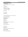
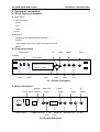
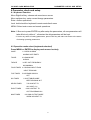
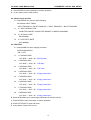
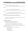
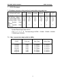
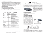
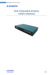
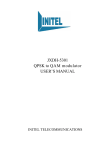
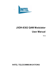
SV-3650D DVB QAM modulator User’ s manual SV-3650D QAM modulator CONTENT CONTENT 1 SAFETY INSTRUCTIONS… … … … … … … … … … … … … … … … … … … … … … … … 1 2 COMPOSITIONS OF SYSTEM AND OPERATING PRINCIPLE… … … … … … … 2 2.1 COMPOSITIONS OF SYSTEM… … … … … … … … … … … … … … … … … … … … … … … … 2 2.2 OPERATING PRINCIPLE… … … … … … … … … … … … … … … … … … … … … … … … … … 2 3 MAIN FEATURES… … … … … … … … … … … … … … … … … … … … … … … … … … 3 4 TECHENICAL SPECFICATION - … … … … … … … … … … … … … … … … … … … … 4 4.1 DATA INTERFACE… … … … … … … … … … … … … … … … … … … … … … … … … … … … 4 4.1.1 ASI INTERFACE… … … … … … … … … … … … … … … … … … … … … … … … … … … … … 4 4.1.2 SPI INTERFACE… … … … … … … … … … … … … … … … … … … … … … … … … … … 4 4 . 2 I F I N T E R FA C E … … … … … … … … … … … … … … … … … … … … … … … … … … 4 4.3 RF INTERFACE … … … … … … … … … … … … … … … … … … … … … … … … … … … 5 4.4 SIGNAL CHANNEL ENCODING… … … … … … … … … … … … … … … … … … … … … … … … 5 4.5 NETWORK MANAGEMENT INTERFACE… … … … … … … … … … … … … … … … … … … 5 4.6 POWER SUPPLY… … … … … … … … … … … … … … … … … … … … … … … … … … … … 5 4.7 OPERATION ENVIORMENT… … … … … … … … … … … … … … … … … … … … … … … … 5 4.8 RADIATION AND SAFETY STANDARD… … … … … … … … … … … … … … … … … … … … 6 4.9 MECHANICAL CHARACTERISTICS:… … … … … … … … … … … … … … … … … … … … … 6 4.10 E3/DS3 INTERFACE (OPTIONAL) … … … … … …………………… ……… ……………6 SV-3650D QAM modulator CONTENT 5 EQUIPMENT CONNECTIONS - … … … … … … … … … … … … … … … … … … … … … 7 5.1 PANLE DISPLAY AND KEYBOARD … … … … … … … … … … … … … … … … … … … … … 7 5.2 FRONT PANEL SKETCH … … … … … … … … … … … … … … … … … … … ……………… 7 5.3 REAR PANEL SKETCH … … … … … … … … … … … … … … … … … … … … … … … … 7 5.4 SPI INPUT AND OUTPUT INTERFACE CHARACTERISTICS … … … … … … … … … … … 8 6 PAR AME TE R S E TUP … … … … … … … … … … … … … … … … … … … … … … … 9 6.1 KEYBOARD FUNCTION… … … … … … … … … … … … … … … … … … … … … … … … … … 9 6.2 OPERATION MODE SELECT… … … … … … … … … … … … … … … … … … … … … … … … 9 6.3 HOW TO SETUP AND CHANGE PARAMENTERS… … … … … … … … … … … … … … … 10 7 QAM MESSAGES… … … … … … … … … … … … … … … … … … … … … … … … … … 17 8 SYSTEM ERRORS AND DEBUGGING… … … … … … … … … … … … … … … … … … 18 8.1 INDICATOR LIGHTS … … … … … … … … … … … … … … … … … … … … … … … … 18 8.2 TROUBLE SHOOTING … … … … … … … … … … … … … … … … … … … … … … … … … 18 9 NETWORK MANAGEMENT… … … … … … … … … … … … … … … … … … … … … 19 1 Safety instruction 1.1 Before starting using this unit, please be sure to refer to this manual. 1.2 Do not to open the cabinet, otherwise the guarantee to repair are not available. Meanwhile touching the inside makes you in great danger of electric shock. 1.3 Please make sure to cut off the power supply if you will not use this unit in long term, and do not use any broken jack, which could result in fire or electric shock. 1.4 Wet hands are forbidden to touch the power jack, to avoid risk of electric shock. 1.5 Please pull the plug itself instead of the wire when you pull out power plug,. 1.6 Any thing flammable and metal or liquid, which will destroy the unit, must be kept out the box. 1.7 Do not place this unit in a location near a heat source such as radiator or air ducts, or in a place exposed to direct sunlight, excessive dust, moisture, rain, mechanical vibration. 1.8 Keep the device working in a good ventilative environment, if not the destruction will occur. 1.9 Please keep the packaging for the safety of transit. NOTE: After all parameters are set up, please press the LOCK button. When LCD display is dark, the protection function takes effect. 1 SV-3650D QAM MODULATOR COMPOSTION OF SYSTEM AND OPERATING PRINCIPLE 2、Composition of system and operating principle 2.1 Composition of system THE SYSTEM CONSISTS UNITS OF THE FOLLOWING CHART IF OUTPUT 35.25/36/36.15/44MHz SPI ASI DS3 DATA QAM IF RF PROCESSING MODULATING PROCESSING UP-CONVERTER RF OUTPUT 48~860Mhz E3 CPU LED LCD KEYBOARD NETWORK MANAGEMENT INTERFACE QAM Digital Modulator is mainly composed of the following modules: Data processing unit The unit converts signals from different interfaces into standard signal, then make data processing to carry out the preprocess of QAM modulating. QAM modulating unit The unit modulates data stream into frequency spectrum signal. IF output is 35.25/36/36.15/44MHz. RF Up-converter unit The unit up-converts IF signals to RF signals from 48MHz to 860MHz, divided into segments. ● CPU/LCD/LED/Keyboard unit The unit carries out keyboard input, LED display and intelligent control, etc. 2.2 Operating principle SV-3650 QAM Digital modulator converts input data streams into frequency signals, it meets to DVB-C standard. Signals from MPEG-II compact encoder or multiplexer was sent into QAM modulator. According to DVB standard, such as interlacing, RS error correction encoding, etc. After IF processing and up-converting into the range of TV channels, signals can be transmitted through HFC and MMDS networks. It’ s widely used in digital TV, data broadcasting, VOD, Internet, video conference etc. 2 SV-3650D QAM MODULATOR MAIN FEATURE 3. Main features Support ITU-T J.83A and B DVB-C Standard Constellation:16QAM、32QAM、64QAM、128QAM、256QAM Input interface: ASI and SPI (or DS3 /E3 optional) Input bit rate: 1.5~51.6Mbps Output bit rate:2~56Mbps Output bit rate:1.15~8.05MHz(Modulus 0.15) Output symbol rate:1~7Mbaud/s RF output:48~860MHz Output level:105dBuV~115dBuV(step adjustable) 188/204 packet automatic identification NIT mapping and sending function,support 44 NIT mapping 10 PID filter and re-mapping PSI/SI information pick-up, parse and modification SI information replacement and insert Input data null packet filtering and output data filling. PCR correction Show and inspect system input bit rate and valid bit rate real time 3 SV-3650D QAM MODULATOR TECHNICAL SPECIFICATION 4. Technical specification 4.1 Data interface 4.1.1 ASI interface (Asynchronous Serial interface) A:Input: Connector: BNC Impedance: 75Ω Packet format: 188/204 bits Access data rate: 270Mbps Max valid bit rate: 51.6Mbps DVB standard B: Loop output: Connector: BNC Impedance: 75Ω 4.1.2 SPI input interface (Synchronous Parallel interface) Connector: DB-25 female Packet format: 188 or 204 bits DVB Standard: LVDS 4.2 IF interface A: IF input Connector: BNC Impedance: 50Ω IF frequency: 35.25/36/36.15/44 MHz (optional) IF Bandwidth≤8MHz Reflect loss ≥18dB Input level: 100dBuV (rms) B:IF loop output: Connector: BNC Impedance: 50Ω IF frequency: 35.25/36/36.15/44 MHz (optional) IF Bandwidth≤8MHz Reflect loss ≥18dB Output level: 100±2dBuV(rms) 4 SV-3650D QAM MODULATOR TECHNICAL SPECIFICATION 4.3 RF interface A. RF output: Connector: BNC Impedance: 75Ω Output Frequency: 48~800MHz Reflect loss ≥15dB Output level: 105~115dBuV (adjustable) Carrier rejection: > 55dB SNR(out of band):≥50dB B: RF output for test Connector: BNC Impedance: 75Ω Output level: 85dBuV~105dBuV (adjustable) 4.4 Channel signal encoding Constellation: 16QAM, 32QAM, 64QAM, 128QAM, 256QAM. Channel encoding: RS encode, DVB standard MER:≥42dB SNR(out of band):≥50dB 4.5 Network management interface IEEE802.3 ETHERNET, RJ45 interface Software protocol: SNMP protocol 4.6 Power supply Voltage: 165V~265VAC or 85V~265VAC Frequency: 50Hz2% Power consumption: 50W 4.7 Operation environment Operation temperature: +5~45C; Storage temperature: -25~+55C. Relative humidity: 10~75% 5 SV-3650D QAM MODULATOR TECHNICAL SPECIFICATION 4.8Radiation and safety Up to GB13837-92 and GB8898-88 4.9 Mechanic characteristics Dimension: 44.5mm(1U)*483mm*(19”)*400mm Weight: 7kg 4.10 E3 /DS3 Interface (optional) A: Input (G.703 standard) Connector: BNC Impedance: 75Ω Packet format 188/204 bits Bit rate: E3/DS3 No-frame format (34.368Mbps/44.736Mbps) B. Output (loop) Connector: BNC Impedance: 75Ω Note: The information contained herein is subject to change without notice. 6 SV-3650D QAM MODULATOR TECHNICAL SPECIFICATION 5. Equipment connection 5.1 Panel display and keyboard A. Panel display a. LED instruction Power Sync Alarm b: LCD B: Keyboard ARROW KEYS (UP/DOWN/LEFT/RIGHT) ENTER LOCK: press once to lock; press once again to unlock MENU 5.2 Front panel sketch Synchronize Up Right MENU TEST interface LED screen WORKING RF:200.000MHz 64QAM 6.875MBd Power Alarm Left Down Enter Lock 5-1: SV-3650 Front panel 5.3 Rear panel sketch Network Power switch indicator ASI LOOP LOOP output output IF output RF output ▌ ▌ ▌ ● ● Power supply Ethernet interface ASI input DVB SPI Input 5-2:SV-3650 Rear panel 7 DS3/E3 input IF input SV-3650D QAM MODULATOR TECHNICAL SPECIFICATION 5.4 SPI input and output interface characteristics No Signals Description No Signals Description 1 CLK-A Signal clock 14 CLK-B Signal clock 2 GND GROUND 15 GND GROUND 3 D7-A DATA 7 16 D7-B DATA 7 4 D6-A DATA 6 17 D6-B DATA 6 5 D5-A DATA 5 18 D5-B DATA 5 6 D4-A DATA 4 19 D4-B DATA 4 7 D3-A DATA 3 20 D3-B DATA 3 8 D2=A DATA 2 21 D2-B DATA 2 9 D1-A DATA 1 22 D1-B DATA 1 10 D0-A DATA 0 23 D0-B DATA 0 11 DVALID-A 24 DVALID-B 12 PSYNC-A 25 PSYNC-B 13 CABLE DATA AVAILABLE PACK SYNCHRONOUS SHEILD CABLE 8 DATA AVAILABLE PACK SYNCHRONOUS SV-3650D QAM MODULATOR PARAMETER CHECK AND SETUP 6.Parameter check and setup 6.1 Keyboard Function Move Right/Left key: choose sub-menu/move cursor Move up/down key: setup cursor/change parameters Enter: confirm operations Lock: lock/unlock the keyboard /remote-control/exit menu MENU: Select main menu and cancel operations Note: 1.Be sure to press ENTER key after setup the parameters, all new parameters will take effect only without *, otherwise the old parameters will be kept. 2. Under any status of setting parameters, press LOCK key will make unit return to the status of showing operating parameters. 6.2 Operation mode select (keyboard unlocked) Press MENU or ENTER to display main menu circularly ONCE: 1.0 VIEW ALARMS ALARMS LIST EMPTY TWICE: 2.0 QAM MODE 64 QAM THRICE 3.0 RF OUT FREQUENCY 200.0000MHz FOUR TIMES 4.0 SIGNAL INPUT FROM INPUT FROM ASI FIVE TIMES 5.0 BYPASS SWISVH OFF SIX TIMES 6.0 NIT TABLE MODE KEEP ORIGINAL NIT SEVEN TIMES 7.00.0 INPUT TS ALL HAVE: 011 EIGHT TIMES 8.00.0 OUTPUT TS OUT PROGRAMS:011 NINE TIMES 9.0 QAM OUTPUT MODE WORK AS INPUT TS 9 SV-3650D QAM MODULATOR PARAMETER CHECK AND SETUP 6.3 How to setup and change parameters 6.3.1 Setup system parameters A: Press MENU once: display as follows 1.0 VIEW ALARMS ALARMS LIST EMPTY or NO INPUT SIGNAL or RF UNLOCK or BUFFER FULL or SYSTEM ERROR B: Press UP/DOWN key to view/change parameters /select functions ▼ 1.0VIEW ALARMS CLEAR ALL ALARMS C: Press ENTER to store change or confirm operation 1.0 VIEW ALARMS ALL ALARMS BE CLEARED D: Press LEFT/RIGHT to view sub-menu 1 1.1 SET IP ADDR. 120.120.120.160 2 1.2 SET NET MASK 255.255.255.000 3 1.3 SET NET GATE 120.120.120.001 4 1.4 NET STATUS NOT CONNECTED or CONNECTED 5 1.5 SERIAL No.: XXXXXXXXXXXXXXXXXX (18-digits) 6 1.6 VERSION H: XX.XX 7 S: XX.XX 1.7 GET PRESET PARAMETER *FACTORY PRESET Press ENTER to store exchange. 8 1.8 RELOAD IN INFO(Reload input parameters) *RELOAD IN CHANNEL(Reload input channel parameters) 9 1.9 QAM WORK MODE *ITU-T J.83 ANNEX A * ITU-T J.83 ANNEX B E. In any status, press LOCK to exit 10 SV-3650D QAM MODULATOR PARAMETER CHECK AND SETUP 6.3.2 Setup QAM parameters A: Press MENU twice: display as follows 2.0 QAM MODE 64 QAM B: Press UP/DOWN to view/change parameters or select function 2.0 QAM MODE *128 QAM *256 QAM * QPSK * 16 QAM * 32 QAM * 64 QAM C: Press ENTER to store exchange or confirm operation D: Press LEFT/RIGHT to view sub-menu 1 2.1 SYMBOL RATE [36.00]-IF frequency 6.875MBd[38.014Mbps] or 6.875MBd[7.906MHz] While setup new symbol rate, press UP/DOWN key, cursor displays at the ends, then press LEFT/RIGHT key to move cursor to the required position ,and press UP/DOWN again to setup parameters, at last press ENTER to change and store. 2 2.2 BW PREFERENCE UNIT uc Bitrate Press UP/DOWN to display on the second line: *Bandwidth 3 2.3 IF OUT FREQUENCY 36.00MHz*36.15MHz/36.65MHz IF output is 36.15MHz when BW>≥7MHz under 36.15MHz/36.65MHz and IF output is 36.65MHz when BW<77MHz under 36.15MHz/36.65MHz 6.3.3 Setup RF parameters A、Press MENU three times, display as follows 3.0 RF OUT FREQUENCY 200.0000MHz Please refer to SETUP SYMBOL RATE to setup new frequency. B、Press LEFT/RIGHT to view sub-menu 1 3.1 RF OUTPUT LEVEL: 115dBuV or 110dBuV C、Press UP/DOWN to plus or minus 0.5dBuV(don’ t need to press ENTER) 2 3.2 SPECTRUM INVERSION ON*OFF 3 3.3 QAM MODULATION ON*OFF 4 3.4 RF POWER SWISVH ON*OFF 11 SV-3650D QAM MODULATOR PARAMETER CHECK AND SETUP D、Press ENTER to store exchange or confirm operation E、In any status, press LOCK will exit. 6.3.4 Select input interface A、Press MENU four times to show following 4.0 SIGNAL INPUT FROM INPUT FROM ASI* INPUT FROM SPI* INPUT FROM E3* INPUT FROM DS3 1 4.1 INPUT SIGNAL TYPE 188 BYTES PACKET or 204 BYTES PACKET or INPORT NOSIGNAL 2 4.2 IN TS ALL RATE 038.051Mbps 3 4.3 TS EFFECT RATE 033.160Mbps 6.3.5 PID Filter A、Press MODE five times, display as follows 5.0 BYPASS SWISVH ON *OFF 1 5.1 BYPASS PID0 CH1 0032 → 0032(D)(PID By-pass) 2 5.2 BYPASS PID1 CH1 0032 → 0120(D)(PID Map) 3 5.3 BYPASS PID2 CH1 0032 → 8191(D)(PID Filter) 4 5.4 BYPASS PID3 CH1 8191 → 8191(D)(Empty packet filter) 5 5.5 BYPASS PID4 CH1 8191 → 8191(D)(Empty packet filter) 6 5.6 BYPASS PID5 CH1 8191 → 8191(D)(Empty packet filter) 7 5.7 BYPASS PID6 CH1 8191 → 8191(D)(Empty packet filter) 8 5.8 BYPASS PID7 CH1 8191 → 8191(D)(Empty packet filter) B. Press UP/DOWN key to view/change parameters or select functions C. Press ENTER to store exchange or confirm operation D. Press LEFT/RIGHT to view sub-menu. E. In any status, Press LOCK to exit. 12 SV-3650D QAM MODULATOR PARAMETER CHECK AND SETUP 6.3.6 Insert NIT A、Press MENU six times, display as follows 6.0 NIT TABLE MODE(Exchange NIT mode) KEEP ORIGINAL NIT *EXCHANGE ORIGINAL NIT 1 6.1 NETWORK ID 00001(read only) 2 6.2 NETWORK NAME TEST(read only) 3 6.3 CHANNELS IN NIT 001(read only) B、Above is controlled by NMS. 6.3.7 View TS input data A、Press MENU seven times or ENTER three times, display as follows 7.00.0 INTPUT TS ALL HAVE:011(Enter number of channels) B、Press LEFT/RIGHT to view TS ID 1 7.00.1 INPUT SIGNAL INPUT 188 TS PACKET(read only) 2 7.00.2 IN TS TS_ID 00010(read only) 3 7.00.3 IN TS ON_ID 00001(read only) 4 7.00. 4 IN TS ALL RATE 038.051Mbps(read only) 5 7.00.5 TS EFFECT RATE 033.160Mbps(read only) C、Press UP/DOWN to view all channels’source. 1 7.01.0 PROG01 NAME(NAME FOR CHANNEL SET 1) CCTV 4(read only) 2 7.02.0 PROG02 NAME(NAME FOR CHANNEL SET 2) CCTV 9(read only) 3 7.03.0 PROG03 NAME(NAME FOR CHANNEL SET 3) 13 SV-3650D QAM MODULATOR PARAMETER CHECK AND SETUP CCTV OPERA(read only) | | | 11 7.11.0 PROG11 NAME(NAME FOR CHANNEL SET 11) SHENZHEN(read only) D、When in the following mode, press LEFT/RIGHT key to view and modified all program information. Press ENTER to store changes; press MENU to quit from current mode. 7.01.0 P01 NAME (NAME FOR PROGRAM 1) CCTV 4(read only) 1 7.01.1 PROG01(CHA01) (PROGRAM 1 OUTPUT OPTION) REMULTIPLEXED/*NOT BE MULTIPLEXED(optional) 2 7.01.2 P01 CODE RATE(CHA01) (ENTER PROGRAM 1’ S VALID BIT RATE) 004.075Mbps(read only) 3 7.01.3 P01 PMT PID (PROGRAM 1’ s PCR PID) 0100(HEX) 0256(DEC) (read only) 4 7.01.4 P01 PCR PID (PROGRAM 1’ s PCR PID) 0902(HEX) 2306(DEC) (read only) 5 7.01.5 P01 MPEG-2 V(PROGRAM 1’ S VIDEO PID) 0200(HEX) 0512(DEC) (read only) 6 7.01.6 P01 MPEG-2 A (PROGRAM 1’ S AUUDIO PID) 028A(HEX) 0650(DEC) (read only) ***ALL SETTINGS FOR OTHER PROGRAMS ARE THE SAME AS ABOVE 6.3.8 TS OUTPUT SETTING A、Press MENU 8 times or ENTER 2 times to see the following: 8.00.0 OUTPUT TS OUT PROGRAMS:011(NUMBER OF PROGRAM OUTPUTING) B、Press LEFT/RIGHT key to view and modify TS ID. 1 8.00.1 OUTPUT TS_ID (OUTPUT TS ID) 14 SV-3650D QAM MODULATOR PARAMETER CHECK AND SETUP 00010(CHANGEABLE) 2 8.00.2 OUTPUT ON_ID (ORIGINAL OUTPUT ID) 00001(CHANGEABLE) 3 8.00.3 CAT WORK MODE MAKE A NEW TABLE (Insert New CAT Chart) *NOT MAKE NEW TABLE(Do not Insert New CAT Chart) 4 8.00.4 SDT WORK MODE(SDT Control Mode) MAKE A NEW TABLE (Insert New SDT Chart) *NOT MAKE NEW TABLE(Do not Insert SDT Chart) C、Press UP/DOWN key to view all program source. 1 8.01.0 P01 FROM(PROGRAM 1 SOURCE) PROGRAM 01 IN CHA01(ALL PROGRAMS FROM CHANNEL 1 ARE FROM SAME /ONE END) 2 8.02.0 P02 FROM(PROGRAM 2 SOURCE) PROGRAM 02 IN CHA01(ALL PROGRAMS FROM CHANNEL 1 ARE FROM SAME /ONE END) 3 8.03.0 P03 FROM(PROGRAM 3 SOURCE) PROGRAM 01 IN CHA01(ALL PROGRAMS FROM CHANNEL 1 ARE FROM SAME /ONE END) | | | 11 8.11.0 P11 FROM(PROGRAM 11 SOURCE) PROGRAM 11 IN CHA01(ALL PROGRAMS FROM CHANNEL 1 ARE FROM SAME /ONE END) D、While in the following mode, press LEFT/RIGHT key to view/modify all programs information. Press ENTER to confirm changes; press MENU to quit from current operation. 1 8.01.1 P01 NAME(NAME OF PROGRAM 1) CCTV 4(CHANGEABLE) 2 8.01.2 P01 NUMBER(PROGRAM 1’ S ID) 00001(CHANGEABLE) 3 8.01.3 P01 PMT PID(PROGRAMS 1’ S PCR PID) 15 SV-3650D QAM MODULATOR PARAMETER CHECK AND SETUP 0100(HEX) 0256(DEC) (CAN BE RE-PROJECTED, SET TO 8191 AND FILTER PID CONTENT) 4 8.01.4 P01 PCR PID (OUTPUT PROGRAM 1’ S PCR PID) 0902(HEX) 2306(DEC) (CAN BE RE-PROJECTED, SET TO 8191 AND FILTER PID CONTENT) 5 8.01.5 P01 MPEG-2 V(OUTPUT PROGRAM 1’ S VIDEO PID) 0200(HEX) 0512(DEC) (CAN BE RE-PROJECTED, SET TO 8191 AND FILTER PID CONTENT) 6 8.01.6 P01 MPEG-2 A(OUTPUT PROGRAM 1’ S AUDIO PID) 028A(HEX) 0650(DEC) (CAN BE RE-PROJECTED, SET TO 8191 AND FILTER PID CONTENT) ***ALL SETTINGS FOR OTHER PROGRAMS ARE THE SAME AS ABOVE Press LEFT/RIGHT can view and modify all information. Press ENTER to confirm changes made; press MENU to quit current operation. 6.3.9 INTERNET DATA SETTING A、Press MENU nine times or ENTER once to show the following: 9.0 QAM OUTPUT MODE(QAM OUTPUT SETTING) WORK AS INPUT TS(MODULATE ACCORDING TO INPUT TS SIGNAL) * WORK AS OUTPUT TS(MODULATE ACCORDING TO OUTPUT TS SIGNAL) B、Press LEFT/RIGHT key to view and modify internet settings. Press ENTER to confirm changes; press MENU to quit current operation. 1 9.1 QAM OUTPUT PARA(QAM OUTPUT DATA SETTING) WORKING AS SETTING * REBUILDING PARA Or NEED REBUILD PARA 16 SV-3650D QAM modulator QAM messages 7、QAM Messages 7.1 Relations between coding method, band width and symbol rate. CODING METHOD QPS 16QAM K 2 4 Min. Bit Rate(Mbps) 14 28 Max. Bit Rate(Mbps) 1.15 Min. Band Width (MHz) 1.15 8.05 8.05 Max Band Width(MHz) 1 1 Min. Symbol Rate (Mbaud) Max. Symbol Rate 7 7 (Mbaud) Band Width=1.15×Symbol Rate 128QA 256QA 6 42 1.15 8.05 1 M 7 49 1.15 8.05 1 M 8 56 1.15 8.05 1 7 7 7 32QAM 64QAM 5 35 1.15 8.05 1 7 Symbol Rate=Output data rate÷m m=2,4,5,6,7,8 Corresponding to QPSK,16QAM,32QAM,64QAM, 128QAM and 256QAM 7.2 Max. transmission band width for 8MHz CODE C/N Limit Max. Rate Utilize Rate 16QAM 22dB 25.8Mbps 3.2 bit/Hz 32QAM 25dB 32.2Mbps 4.0 bit/Hz 64QAM 28dB 38.7Mbps 4.8 bit/Hz 128QAM 31dB 44.2Mbps 5.5 bit/Hz 256QAM 34dB 51.6Mbps 6.4 bit/Hz Effective input data rate=Output rate×188÷204 17 SV-3650D QAM modulator System errors and debugging 8、System errors and debugging 8.1 Indicator lights There are three LED indicator lights. 1) “POWER”lights up (Red) means power switch on and working orderly. 2) “SYN”lights up(Green) means synchronization clock working orderly. 3) “ALARM”lights up(Green) means data processing working orderly. 8.2 Trouble Shooting 8.2.1 The ”POWER”indicator light does not illuminate. Please check the wire to make sure the wire is connected to the socket properly and the power switch is on. 8.2.2 “STATUS”illuminates(in red) This means lack of synchronal signals or input data abnormal or no valid data input, please check the input data cable is connected properly, and the input interface is selected correctly. If the answer is yes, it means the unit is broken, needs to be replaced. 8.2.3 “ALARM”flashes This means the equipment is out of order for some faults. Please debug according to the instruction from LCD. 18 SV-3650D QAM modulator Network management 9、Network management The unit could be controlled remotely via network management software. It needs authorization. Please refer to 《NMS user’ s manual》 19