1
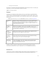
The SQIID User's Manual
•
•
•
•
•
•
•
•
•
1. Introduction
2. Instrument Description
3. Command, Communication, and Control
4. The InSb Detector Array
5. Observing Run Preparation
6. The IR Instrument Control System -- WILDFIRE
7. Observing Practices
8. Calibration
9. Appendices
o Appendix I: Telescope Checklist
o Appendix II: WILDFIRE Command List for SQIID
o Appendix III: Troubleshooting
o Appendix IV: Data Reduction Guide
o Appendix V: TCL Scripting Synopsis
o Appendix VI: Cautions and Caveats
o Appendix VII: Changes to SQIID
o Appendix VIII: Representative WILDFIRE Interchange
o Appendix IX: Installation Issues
o Appendix X: ToO Observations
o Appendix XI: FYI
1. Introduction
The NOAO SQIID Infrared Camera (Simultaneous Quad Infrared Imaging Device) produces simultaneous
images of the same field in the J, H, K, and narrowband L filters, using individual 512X512 quadrants of
ALADDIN InSb arrays and is designed for use at the f/15 Cassegrain foci of the KPNO 2.1-m and 4-m
telescopes. The observations are generally background (photon statistics) limited. The designated array for
each channel is selected for characteristics (read noise, settling time, and dark signal) appropriate to
background limited operation under actual observing conditions for its single filter. SQIID, which serves as
its own acquisition camera, is a good match to "point and shoot" observing at the 2.1-m without a telescope
operator. The filters are fixed in place and dark slide and window covers are the only moving parts. SQIID
employs closed cycle refrigeration instead of liquid cryogens and in its prior configuration operated
flawlessly for periods as long as 40 days, providing an unparalleled degree of system stability. Typical
observing programs include:
•
•
•
taking a few (2-5) exposures on the same target with small offsets (to counter ghosts and bad
pixels and improve spatial sampling of the images);
taking many exposures of the same target with a dither pattern of offsets (to build up long
exposures);
spatial mosaics of dithered pairs of images covering larger regions with limited overlap between
images (to build up large images).
Each detector is a Raytheon Vision Systems (nee SBRC) ALADDIN 1024X1024 indium antimonide (InSb)
hybrid focal plane array with 27 micron pixels (90% geometric and 100% optical fill factors) produced
1
under contract to the ALADDIN Consortium. The ALADDIN Consortium, consisting of NOAO/KPNO
and the US Naval Observatory, Flagstaff, under the engineering guidance of Al Fowler, has designed,
developed, characterized and optimized the performance of the ALADDIN array for the wider community.
Since each SQIID channel illuminates a single 512X512 quadrant, devices need only one otherwise
excellent operable quadrant to be acceptable. The optics for each channel are independently optimized with
a relatively narrow bandpass (apart from the entrance window, which is shared in common), permitting
high efficiency AR coatings to deliver high instrumental throughput. The four separate channels are cofocused and co-aligned with a minimum overlap region of roughly 500X500 pixels common to all channels
and are physically edge-masked to stop stray light from entering (or leaving) the readout. The detectors are
of sufficiently high quality and uniformity that the dark/sky subtracted raw data are useful in assessing data
quality in near real-time.
Detector area, stability, uniformity, quantum efficiency, low read noise and dark signal combine to make
SQIID the system of choice for any observation which requires multi-color (JHK) imaging over large areas
of the sky, quick look at transient targets, and for deep observations of selected regions. IR observations of
necessity consist of sequences of frames with interspersed telescope motions. Each set includes a subset of
small telescope motions (dithering) to dodge bad pixels and provide better image sampling and may require
equal time spent off target (especially when observing extended sources and/or crowded fields). Typically
the minimum time spent on taking a complete set of frames at a given field (within detector FOV) can be
on the order of 10 minutes or more. With a single channel imager, the same set of pointings needs to be
repeated for each filter. Since variations in observing conditions - seeing, airmass, sky transparency, and
atmospheric background - ultimately limit the cohesiveness of a data set, multi-color observations are
necessarily limited in depth and/or areal extent by the mechanics of taking the observations and the
systematic effects of combining them into a single coherent data set. The advantage of SQIID is selfevident. During the time necessary to take the observations at the most time consuming wavelength, one in
effect gets the other channels for free under the same observing conditions. Systematic effects are limited
and determinate. This is why SQIID competes favorably with larger format arrays for multi-color
applications. In addition, wide field L band imaging is possible (albeit with restricted bandpass) with
sufficient sensitivity to detect and accurately locate red sources in the field. This feature is particularly
important for detecting and identifying for further study sources with IR excess, highly reddened sources,
and intrinsically cold sources near the galactic plane where the star formation process is still active.
Details of the prior SQIID system are discussed by Ellis et al. 1992 ("The Simultaneous Quad-color
Infrared Imaging Device (SQIID): A Leap Forward in Infrared Cameras for Astronomy" by T. Ellis, R.
Drake, A. M. Fowler, I. Gatley, J. Heim, R. Luce, K. M. Merrill, R. Probst, & N. Buchholz, 1992, in Proc.
SPIE, 1765, pp. 94-106.) and the ALADDIN detectors are discussed by Fowler et al. 1996 ("ALADDIN,
The 1024x1024 InSb Array: Design, Description, and Results", by A. M. Fowler, Ian Gatley, P. McIntyre,
F. J. Vrba, & A. Hoffman, 1996, in Proc. SPIE,2816, pp 150-160).
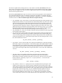
2. Instrument Description
Optical Description
The SQIID optical system, which is matched to f/15, has a demagnification of 4. The pupil masks are fixed
(i.e., not selectable), but a reasonable compromise for the 2.1-m and the 4-m telescopes has been
implemented (n.b., by design, the KPNO IR secondaries handle the central obscuration without requiring a
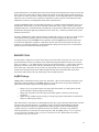
separate cold stop within the pupil mask.) According to Charles Harmer (who has the current design
available), the worst case blur circle for SQIID is about 75 microns with 90% encircled energy. The optical
layout of SQIID is shown in Fig. 1. The f/15 telescope focal plane is located inside the entrance window
near the top of the instrument. A series of dichroics and flat mirrors separates the incoming beam into four
separate wavelength channels, each with its own camera (Lyot stop, filter, optics) and focal plane array.
2
Dichroic #1 passes L and reflects JHK. Dichroic #2 passes H and reflects JK. Dichroic #3 passes J and
reflects K. The telescope exit pupil is imaged at the Lyot stops that are sized to the exit pupil image
diameter to serve as an optical cold stop. Standard astronomical passband filters located at the Lyot stops
restrict the range in wavelength passed to the array.
The system of dichroics is matched to natural atmospheric windows, adequately spaced in wavelength so
that their in-band transmission and out-band reflectivity is very high. Since each camera is designed for
optimum performance over a limited wavelength range, the AR coatings provide unusually high
transmission. The opportunity for optimizing each channel for operation over a restricted wavelength
compensates for transmission losses within the dichroic system and has yielded high throughput in all
channels, comparable to that of a single camera system.
Fig. 1 - Optical layout of SQIID. The elements are identified in the text.
SQIID, which was built in an era where 58X62 was standard and initially deployed (1990-1995) with
256X256 Platinum Silicide arrays, was designed to smoothly accommodate larger devices. The optics was
designed to illuminate a 512X512 array of 25 micron pixels. Since the ALADDIN array has 27 micron
pixels, some vignetting is inevitable. In addition, upon seeing the full FOV for the first time, we discovered
some unintended vignetting in RA within the instrument that would require a substantial effort to rework.
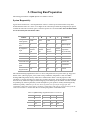
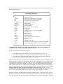
The pixel scale and the unvignetted spatial coverage at the two telescopes are summarized in Table 1.
3
Table 1. Pixel Scale and FOV
Telescope f/ratio arcsec/pixel
# pixels
RA X DEC field (arcsec)
2.1-m
15
0.69
440 X 460 304 X 317
4-m
15
0.39
440 X 460 172 X 179
Filters
Each channel of SQIID has its own fixed filter. We are unable to accommodate other filters tailored to
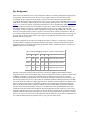
specific programs. The deployed filter complement as of February 2002 is summarized in Table 2. Note:
Prior to February 2002, the K channel contained a Barr K filter.
Table 2. SQIID Filters
vendor
ID
Channel
midpoint
(microns)
FWHM bandpass
(microns)
HP short
(microns)
HP long
(microns)
J
Barr J
1.267
0.271
1.131
1.402
H
Barr H
1.672
0.274
1.535
1.809
K pre
02/2002
Barr K
2.224
0.394
2.027
2.421
K post
02/2002
OCLI Ks 2.225
0.35
1.95
2.30
L
Barr
PAH
0.074
3.262
3.336
3.299
J filter data are estimated from the manufacturer's warm tracing by applying 1.63% shortward shift. Other
data are from manufacturer's 77K tracings. Dichroic transparency has not been applied.
The geometric distortion is comfortably small within the unvignetted area, so that the data from the
different channels can be brought to a common basis using a superposition of linear transforms (position
shift, rotation and magnification) and a modest amount of pincushion/barrel distortion. (Note: J has
pincushion distortion and HK have nearly identical barrel distortion.) The geometric distortion appears to
be radially symmetric and is well represented by the addition of a cubic term. This simplifies the data
reduction enormously, as spatial registration at any channel can be directly translated into registration at all
channels.
Since the individual channels of SQIID illumine a single quadrant of a four quadrant array (which is has to
be physically mounted within a small volume so as to not interfere with its neighbors) and the best quadrant
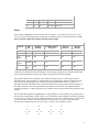
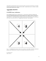
of each device is selected, the relative orientation on the sky on the array is channel specific. From the point
of view of the array, which is read from the outside corner (see Fig. 13, rows are oriented along the
horizontal and columns along the vertical), the sky is "natively" seen oriented as follows:
J
H
W
S
N
N
E
K
W
S
E
S
L
E
E
W
N
N
S
W
4
Initially, SQIID data where displayed and saved oriented as shown. As of September 2000, the saver task
correctly handles the orientation issue during the saver process. Images saved to disk (and
automatically displayed) are properly oriented with North up and East to the left.
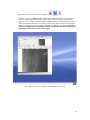
Mechanical Description
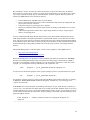
Located at the telescope focal plane are the imager cryostat, the mechanical interface, and the associated
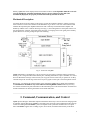
warm electronics in two boxes mounted to the instrument. Fig. 2 shows a side view of the instrument and
identifies the important parts. SQIID communicates with a remotely located instrument computer and
ultimately with the user in a remote observing room (Fig. 3). Even though the f/15 focal plane at the 4-m is
well back from the "nominal" focal plane of the telescope, a re-imaging lens in each guide probe assembly
permits them to be used for guiding and precision offsetting.
Fig. 2 - Side View of SQIID
SQIIDs temperature is maintained by a pair of Closed Cycle Cryogenic Coolers that employ pressurized
helium gas as a refrigerant. Most of the internal parts, including the dichroics, optics, and filters, are cooled
below 70 K with the first stage of the Closed Cycle Cryogenic Coolers. Each array is operated at ~30 K by
a thermal strap to the second stage of the Closed Cycle Cryogenic Coolers plus a closed loop heater circuit.
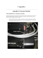
Refer to Fig. 2 to identify the external features of the instrument. SQIID will be cabled upon installation,
and should not be uncabled for any reason without contacting KPNO staff first. The only necessary
user contacts with the focal plane instrument are the instrument power switch located on the electronics box
and the mechanisms for inserting the internal and external dark slides.
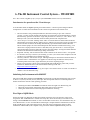
3. Command, Communication, and Control
SQIID operates through a distributed computer network that has slowly evolved to the meet changing needs
of computer support. Historically SQIID was operated by the user from a SUN workstation in the telescope
control room through the WILDFIRE system, a transputer based system that communicates over optical
fibers. WILDFIRE supports fast co-adding in place, movie mode, and data transfer directly to the SUN.
5
Since WILDFIRE is tied to Sbus based hardware and a SunOS host system there is little room for growth in
the core machine. The system was hard pressed by the upgrade from four 256X256 arrays to four 512X512
arrays during the SQIID upgrade. Movie mode was dropped owing to I/O delays associated with this
upgrade.
The current configuration has SQIID remotely operated from a Linux-based Workstation (physically
located in the control room) that connects to the SQIID host Sun Workstation (now completely in the
computer room) through a VNC server.
The WILDFIRE system uses transputers and transputer links to control and acquire data from SQIID. A
transputer is a single-chip microcomputer with its own local memory and communication links, which can
operate either by itself or in conjunction with other elements linked to form computing arrays and
networks. The WILDFIRE system consists of three main hardware components:
•
•
•
The SQIID instrument control unit inside the DCU (Digital Control Unit) box contains two
transputers that provide housekeeping data and control and generate the sequences that operate
each array.
The DSP unit (a VME based Digital Signal Processor system located inside the black Heurikon
box in the computer room) contains eight transputers that provide the math processing needed to
do coadding as the data are taken and buffer space for finished data before it is transferred to the
SUN computer.
The B016 unit (a programmable dual-port memory and interface board located inside the black
Heurikon box in the computer room) interfaces the transputers and the SUN and handles the
formatting of data before it is saved to disk.
Communications between SQIID and the DSP take place over transputer links implemented on an optical
fiber cable. The B016 interconnects the transputer DSP to the SUN SparcStation computer via a VME to
SBUS converter within the Heurikon box.
The WILDFIRE user interface on the SUN is implemented within the TCL (tool command language)
environment. On startup, one can configure the image save to produce either FITS images or IRAF images
(via IMFORT routines) so that they can be manipulated and archived to tape within IRAF. The image data
are generated in IEEE 32-bit floating point format. It is important to note that these images are NOT
PROTECTED in any way and can be overwritten if the full path names of existing and new images are the
same. (Currently the saver task attempts to manage conflicting filenames by appending ".nnn" to the
incoming conflicting filename.) The data may be written to Exabyte or DAT tapes on local tape drives or
sent via 'ftp' to one's home institution. Depending on the amount of header information, a single FITS file
of a 512 X 512 image is about 1.057MB and a single 4 color exposure is 4 images (4.2MB).
Under the present version of WILDFIRE data acquisition:
•
•
At the 4-m, SQIID is accessed from the Linux workstation tan which is the connected via VNC to
the SQIID host Sun computer khaki.
At the 2.1-m, SQIID is accessed from the Linux workstation sapphire which is connected via VNC
to Sun computer lapis which handles the SQIID host Sun computer royal remotely.
It is interesting to note that the current arrangement allows SQIID operations to be viewed remotely.
However, since hosting multiple VNC connections places an undue burden on the Sun systems, this is not
recommended for continuous useage.
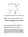
A separate Linux based system serves as the telescope control, with a terminal at the LTO station; a
hardwire link between the TCS and instrument control computers is used to send TCS commands to the
telescope (singly, or within TCL scripts) and to retrieve telescope information for the image header. A
schematic depiction of this arrangement is shown in Fig. 3.
6
Fig. 3 - Schematic configuration of electronics and computers used with SQIID/WILDFIRE
Important Note: The disks within the primary workstations khaki and lapis are designated /data1. At the
2.1-m, WILDFIRE is run on the secondary workstation royal, whose partition is /data2. The disks are
cross-mounted so that access to both is possible from either machine. However, such cross-access (e.g.,
/data1 from royal) is significantly slower than accessing the disk resident in the workstation. Therefore,
it is imperative that the partition used for storing data taken by WILDFIRE be /data2 on the 2.1-m
telescope! While it is possible to designate /data1 as the WILDFIRE data partition, operation will be
much slower and subject to crashes, so don't do it. At the 4-m, one may designate either /data1 or
/data2 as the data partition.
WARNING: Do not let the designated data disk fill up. You will lose data! The filenames may
appear, but they will have zero length. (The WILDFIRE housekeeping screen reports available
space.) See Appendix VI.
4. The InSb Detector Array
The four detectors in SQIID are ALADDIN 1024X1024 hybrid focal plane InSb arrays produced by
Raytheon Vision Systems (nee Santa Barbara Research Center). They consist of a photovoltaic InSb
detector array mated to a silicon direct readout multiplexer via indium bumps. The readout is a p-channel
MOSFET device. The ALADDIN array was cooperatively designed and developed at RIO/SBRC with the
ALADDIN Consortium, consisting of NOAO and the US Naval Observatory, Flagstaff.
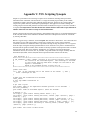
The device is presently operated in a non-destructive readout mode providing double correlated sampling.
A representation of the voltage on a single pixel during an integration and readout is shown in Fig. 4. An
address cycle consists of a "reset" to the canonical detector bias voltage, a non-destructive "read", followed
by a second "read". During the reset operation, the voltage on each pixel is set to the value VR. When the
reset switch is opened, the voltage left on the sense node will differ slightly from VR, due to charge
spillback from the reset gate and from "kTC" noise. After a time 'fdly', the voltage on the pixel is sampled
nondestructively (i.e., without resetting), yielding V1. After a second time interval, defined as the
integration time, the voltage is again sampled, yielding V2. The "signal" is the difference between the two
reads. Note that this technique, known as "double correlated sampling" eliminates the effect of the transient
7
following the reset operation. The intervals indicated (not to scale) at the bottom of Fig. 4 represent the
time required to carry out each operation on the entire array; thus, on an absolute frame, the time at which a
given pixel is reset and read depends on its location in the array.
Fig. 4 - Schematic representation of the voltage on a single pixel as a function of time. The intervals labeled
"reset" and "readout" suggest the time when these events occur and are not to scale.
The operating microcode for ALADDIN arrays includes a provision for "multiple correlated sampling"
(frequently referred to as Fowler sampling in deference to its discovery, Al Fowler of NOAO) in which the
"reads" consist of a series of N nondestructive reads coadded to yield the values V1 and V2. This greatly
reduces (by approximately N0.5) the array read noise on long, low-background integrations. Since SQIID
observations are generally background limited (specifically, they are not detector limited), we only use
"Fowler 1" which corresponds to double correlated sampling. At the shortest integrations (within the
SQIID environment) selecting "coadds >= 2" also improves S/N (by approximately N0.5).
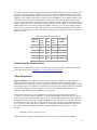
Table 3 summarizes the device characteristics and measured performance levels (according to standard lab
protocol) of the ALADDIN arrays assigned to SQIID. SQIID was designed for background limited
performance at low to moderate backgrounds. The ALADDIN array has 27 X 27 micron pixels with 90%
geometric fill factor (100% optical fill factor) and a 1024 X 1024 format comprised of 4 electrically
independent quadrants. The ALADDIN2/ALADDIN3 readout designation corresponds to improvements in
the readout design. Note: Table 3 reflects the array assignments within SQIID as of February 2002.
The prior configuration was SCA49484_Q3 at H channel, SCA41375_Q3 at K channel and
SCA414107_Q3 at L channel. The bias values listed are effective as of January 2005.
8
Table 3. SQIID Arrays
Characteristic
J
H
K
L
Comments
SBRC
Identification
(Quadrant)
SCA 45986
(Q3)
Readout type
ALADDIN2 ALADDIN2 ALADDIN3
ALADDIN3
version
Response
uniformity
+/-5%
+/-5%
+/-5%
+/-5%
within FOV
Quantum
efficiency
95%
95%
95%
85%
in band
Bias
600
600
700
800
mv
Full well
>200000
>160000
>200000
>300000
electrons
lab read noise
40
45
35
35
electrons rms
lab dark signal @
300mv bias
0.3
0.4
0.6
0.1
electrons/sec
Conversion gain
10
10
11
11
electrons/ADU
Cosmetics
isolated
regions
isolated
pixels
reduced QE
region
isolated
pixels
primary
defects
SCA 46888
(Q4)
SCA 414375 SCA 415412 ALADDIN
(Q2)
(Q3)
InSb
It is useful to note that "dark current" is a function of applied bias and because both "dark current" and read
noise are temperature dependent in opposite senses (below 40K "dark current" decreases with decreasing
temperature to a minimum near 30K and read noise increases with decreasing temperature from a minimum
near 40K) they cannot both be minimized. Hence the array operating temperature is generally selected to
provide an application (background) specific compromise. Further information on the array design and
operation may be found in Fowler et al., Proc. SPIE, 2268,340-345 (1994), and in Fowler et al., Proc.
SPIE, 2816,150-160 (1996). The multiple correlated sampling technique used for read noise reduction is
described in Fowler and Gatley, Ap. J. (Letters), 353, L33 (1990).
Telescope performance is covered in Section 5. The relatively high dark signals listed in Table 4 - which do
not compromise performance - are indicative of compromises in the instrument design (not intended for
low backgrounds), the need to operate at high bias, and the freedom to deploy specific arrays that might be
unsuited to more demanding applications.
9
5. Observing Run Preparation
The limiting performance of SQIID depends on a number of factors.
System Responsivity
Typical observed fluxes for a 10.0 magnitude star at the 2.1-m telescope are listed in Table 4. By direct
measurement the fluxes are a factor of 3.21 higher at the 4-m telescope and the sky background per pixel is
essential the same. The conversion gain is a detector-specific 10-11 electrons/ADU. Note: the biases listed
are not necessarily the current bias values.
Table 4. SQIID Performance on 2.1-m
channel
J
H
K
L
comments
10 mag star
within aperture
3.25e4
2.90e4
1.78e4
?
ADU/sec
Sky brightness
level
98
421
387
???
ADU/sec/pixel
Sky brightness
origin
OH airglow, OH airglow, OH airglow,
scattered
scattered
thermal
light
light
emission
Note:
thermal
components
emission
vary in intensity
Conversion gain 10
10
11
11
electrons/ADU
Bias
600
600
700
800
mv
Full well
>200000
>200000
>200000
>250000 electrons
in situ read noise 40
40
35
35
electrons rms
in situ dark
signal
21
32
197
26
electrons/sec
Minimum
integration time
0.84
0.84
0.84
0.11
seconds
The estimated limiting magnitude for S/N = 3 in 60 sec integration time for a point-source (pt: mag) and a
diffuse-source (diff: mag/square_arcsec) under average conditions (temperature = 50F; 3mm PWV;
midrange OH background) sans sky subtraction is summarized in Table 5. For the purposes of this
calculation, a 10 pixel collecting area on the sky is assumed. In practice, observing limits are dependent on
the mode of sky subtraction employed. When mapping an extended region, the number of frames available
for producing sky frames significantly exceeds the depth at a given position, virtually eliminating the sky
subtraction "penalty". However, for the case where sky frames are exposed for an aggregate time
comparable to that of the source frames, sensitivity is reduced by 0.376* mag (2.5*(log(sqrt(2))) from the
values listed in Table 5 . Such is often the case for deep integrations of individual fields.
Table 5. SQIID limiting magnitude for S/N = 3 in 60 sec
Channel
2.1-m pt
2.1-m diff
4-m pt
4-m diff
J
19.8
20.2
21.1
21.3
H
18.9
19.7
20.2
20.4
K
18.3
19.2
19.6
19.8
PAH
12.3
13.1
13.5
13.7
10
Sky Background
There are two predominant sources of sky background, which are essentially independent, both physically
and spectrally. The transition between the two occurs at approximately 2.3 microns. Short of this
wavelength, the sky background is dominated by emission lines from OH in the upper atmosphere
(typically 90 km altitude). The strength of these lines can vary over the course of the night with a timescale
on the order of an hour; in addition, upper level winds generate inhomogeneities and overall motion of the
airglow. As a result, the intensity of the background emission can vary unpredictably during the night.
Beyond 2.3 microns, thermal emission from the telescope optics and sky is the predominant background.
This roughly follows a blackbody at ~300K temperature and increases very rapidly with increasing
wavelength. To further complicate matters, atmospheric lines (primarily H2O, HDO, CH4, and N2O), which
show up as absorption features in spectra, appear as emission features in the sky background, so that the
loss of signal and the increase in background are temperature and wavelength dependent. For imaging one
generally ignores the finer points and treats the longer wavelength filters like their shorter wavelength
brethren when processing data.
One must be prepared for the simple fact that IR observations are subject to a wider range of sensitivity
variations linked to changing environmental conditions (OH airglow and temperature) than the optical,
where phase of the moon and sky transparency predominate. Table 6 estimates the relative sensitivity for
SQIID for three levels of OH airglow.
Table 6. Estimated SQIID performance variation with OH airglow
Airglow
low
J
H
K
L
Comments
+0.25 +0.25 +0.08 +0.00 magnitudes improvement
medium +0.00 +0.00 +0.00 +0.00 magnitudes improvement
high
-0.24 -0.20 -0.10 +0.00 magnitudes improvement
Estimates of the relative background and sensitivity variation for SQIID for three different ambient
temperatures and 4 values of Precipitable Water Vapor are summarized in Table 7 and Table 8 respectively.
At KPNO, 1mm PWV is a winter rarity and 9mm PWV is a Monsoon Season staple. It is useful to
remember that the thermal background comes from both the atmosphere (which varies with airmass) and
the telescope (which does not vary with airmass) in comparable quantities. Although observations at JHK
are onscale under all conditions, at high temperature the L channel can saturate and become unusable. The
primary symptom of saturation is an East/West gradient in the L background at the shortest integration
times. If one desperately needs to perform L channel observations under higher temperature conditions,
insertion of the cold internal polarizer element (it is the third choice in the open/dark/polarizer position
controlled by the hand crank on the instrument) drops the background (and the signal!) by a factor of two,
with edge vignetting (because it is too small to service the full FOV). Although one can obtain useful data
at JHKL within the central field with the polarizer in place, the vignetting near the edge (which is variable,
since we do not put a close tolerance on the indication when the polarizer is in position) is problematic. It is
also worth remembering that for polarized sources your signal loss will be larger.
11
Table 7. Estimated SQIID performance variation: ambient temperature
Ambient
Temperature
J
H
K
L
comments
30 F
+0.00 +0.00
+0.21
(0.7)
+0.35
(0.5)
magnitudes improvement
(background relative to 50F)
50 F
+0.00 +0.00
+0.00
(1.0)
+0.00
(1.0)
magnitudes improvement
(background relative to 50F)
70 F
+0.00 +0.00
-0.30
(1.7)
-0.31
(1.8)
magnitudes improvement
(background relative to 50F)
Table 8. Estimated SQIID performance variation: Precipitable Water Vapor
PWV
J
H
K
L
comments
9mm +0.00 +0.00
-0.02
(1.02)
-0.19
(1.12)
magnitudes improvement
(background relative to 6mm)
6mm +0.00 +0.00
+0.00
(1.00)
+0.00
(1.00)
magnitudes improvement
(background relative to 6mm)
3mm +0.00 +0.00
+0.03
(0.98)
+0.26
(0.84)
magnitudes improvement
(background relative to 6mm)
1mm +0.00 +0.00
+0.06
(0.95)
+0.54
(0.67)
magnitudes improvement
(background relative to 6mm)
System Overheads
To optimize observing efficiency, it is important to keep the two distinctly different system overheads in
mind, related to:
•
•
Data pipeline flow (~40 sec, roughly fixed)
Mode of array operation (mode dependent)
It takes time to move the data from the instrument through the distributed hardware out into storage on the
Sun Workstation. During this time, critical resources are involved which do not lend themselves to
overlap/reuse, so that the start of a new integration must be held off until the pipeline is clear. For an
externally realized integration, it currently takes 40 seconds following the last readout to safely deliver the
results. Since the actual disk write time is but a fraction of this total, little time is to be gained, for example,
by electing to not save undesired channels to disk.
The preferred method for improving observing efficiency involves internal co-addition, since co-addition of
JHK frames entails an overhead of only 10 millisec. By co-adding integrations to produce the equivalent of
a 1 to 3 minute integration, the effect of data pipeline flow overhead is minimized.
The mode of array operation also has a significant impact on observing efficiency. In particular, it is
important to understand the role of minimum JHK integration time in the JHK observing efficiency. SQIID
currently employs global reset and double correlated sampling to produce an image: each image is the
difference between two reads of the array and the minimum integration time is roughly the time to read the
array once. Consequently, at the shortest integration times (approaching the minimum integration time of
order 1 sec) the observing efficiency declines to 50% and for integration times of order 10 seconds, the
JHK observing efficiency approaches 90%.
12
It is equally important to understand the relationship between JHK integration time and L integration time
that affects L observing efficiency. During the course of an integration, SQIID simultaneously resets the
JHK arrays, then simultaneously performs a non-destructive read (equivalent to a CCD bias frame) on the
JHK arrays, waits roughly an integration time then reads out the JHK arrays again. Between JHK reads, the
L band array is read out (in pairs and differenced) as often as will fit between the JHK read pair and the
results co-added. Since there is some dead time before running L and since the minimum integration time is
roughly the readout time, the maximum time spent integrating at L within a JHKL cycle is less than half the
JHK integration time. One could use a different technique to read L (e.g., row reset) to improve efficiency,
but we have yet to produce the complex code required to read L differently than JHK and will most likely
produce a code employing row reset for all channels. The situation is summarized in Table 9 for the case of
the shortest L time:
Table 9. L channel observing efficiency
L time per
coadd (sec)
JHK
time
(sec)
L
coadds
total L
time
(sec)
% time
(L/JHK)
0.11
1.00
1
0.11
11.0%
0.11
2.00
6
0.66
33.0%
0.11
3.00
10
1.10
36.6%
0.11
5.00
19
2.09
41.8%
0.11
10.00
42
4.62
46.2%
0.11
15.00
65
7.15
47.7%
Channel Specific Characteristics
Channel specific characteristics, such as scans of the filters, geometric distortion, and representative bad
pixel masks can be found at Supplement 1: Channel Specific Characteristics
.
Other Preparations
Object Coordinates for any epoch can be entered into the telescope computer for use during the run.
Although this task could be done by the telescope operator during the course of the night, lengthy
observing lists are best entered by electronic submission (see below). These may include objects, standards,
offset and guide stars, etc. Acquisition of optically faint or invisible objects might require initial acquisition
and coordinate updating on a nearby bright star, so advance selection of these offset stars can save
considerable time while observing. SQIID does not use a guider.
Conscientious observers may send coordinate lists via email (two weeks or more before the run) to
[email protected]. Files should be ASCII text, no longer than 2000 lines. Start the file with your name, a
cache name, telescope, and dates of the observing run. Coordinates will be checked for format, loaded into
the appropriate telescope computer, and acknowledgement will be sent. Each object should be one line of
text. The format is object name, RA (starting column 16 or greater, delimited by first blank after col 15;
hours, minutes, seconds), DEC (degrees, minutes, seconds), and epoch. Each field should be separated by
one or more spaces (NO TABS); the delimiter in the RA and DEC fields may be spaces or colons.
Example:
•
alpha nuti 12:34:56.7 -89:59:59.9 1734.4
Further details may be found in the June 1992 NOAO Newsletter or the new Observers Handbook.
13
Standards are a subject of continuing discussion, and probably will remain so for some time. For the
purposes of determining and removing the effects of telluric absorption and throughput in the instrument, it
is desirable to observe a calibration star as near as possible to the object in both space and time. Owing to
its high sensitivity and relative coarse pixel scale, SQIID must be calibrated using standard stars fainter
than JHK=9mag. Recent compendia of faint standards are extremely useful in this regard:
•
•
•
A New System of Faint Near-Infrared Standard Stars by S.E. Persson, D. C. Murphy, W.
Krzeminski, M. Roth, and M. J. Rieke in Astron. J., 116:2475-2488 (1998).
Northern JHK Standard Stars for Array Detectors by L. K. Hunt, F. Mannucci, L. Testi, S.
Migliorini, R. M. Stanga, C. Baffa, C., F. Lisi, and L. Vanzi in Astron. J., 115:2594-2603 (1998).
JHK standards for large telescopes: the UKIRT Fundaental and Extended lists by Timothy G.
Hawarden, S. K. Leggett, Michael B. Letawsky, David R. Ballantyne, and Mark M. Casali in mon.
Not. R. Astron. Soc., 325:563-574 (2001).
Visitors should arrive on the mountain at least by early afternoon of the first night. This will allow time to
become familiar with the instrument, create and test observing parameter sets, and enter object coordinates
into a cache. First-time users of SQIID may wish to arrive a day early and spend some time in the evening
looking over the shoulder of the previous observer, with his/her prior permission.
14
6. The IR Instrument Control System -- WILDFIRE
Note: This contains a SQIID-specific synopsis of the WILDFIRE manual written by Nick Buchholz.
Interim notes for operation at the 2.1-m telescope
As of December 2006, the SQIID operating environment at the 2.1-m telescope has changed with the
incorporation of a Linux-based workstation as the console for operations in the control room:
The two monitors, along with keyboard/mouse, that used to belong to lapis now connect to
sapphire, a Centos 5 Linux machine. The monitors are in Xinerama mode which produces a display
that seamlessly spans the two monitors. Login and password are as before (i.e., user "2meter", etc).
Both lapis and royal reside with their monitors and keyboards in the computer room.
Access to lapis is via VNC. Clicking on the "VNC" icon on the menu bar at the bottom of the left
hand sapphire screen opens the X:1 desktop on lapis, without a need to enter a password. After lapis
reboots, and after an obsinit, this desktop automatically opens the Instrument Control Window.
Please note that people can access this desktop from ANY machine on NOAO network (e.g., if an
observer has a laptop connected to the 2.1 meter hub). They just need to do: % vncviewer lapis:1
and enter the 2meter password. Since this will slow the VNC linkage, viewing from other machines
should not be abused with extended usage during observations..
Important: currently, after an obsinit it takes about 2 minutes for the VNC to restart - so be patient.
If it becomes necessary to reboot royal manually, go to the royal console in the computer room and
use the [L1 A] or [STOP A] keys and then enter boot.
Do not try and run a web browser on lapis. Although Netscape has been removed from the menu, it
can still be run it a command line. Use sapphire for web browsing and other fun stuff (we have
tested the printer and it works). Lapis should only be used for acquiring images.
People can now use the xcdroast icon to burn DVD-Rs and CD-Rs. Bob is gonna send you some
instructions. Meanwhile, here is the documentation and FAQ on the web:
http://www.xcdroast.org/#manual
If just the VNC needs to be restarted, log on to lapis as user 2meter and do: % restart-vnc and after 2
minutes a new one should be ready.
•
•
•
•
•
•
•
Initializing the Environment with OBSINIT
The optical CCD (ICE) and infrared (WILDFIRE) environments are both operated from the same account
on the 2.1-m (2meter) and 4-m (4meter) telescopes. The all-important obsinit command performs a
number of functions relevant to this operating procedure.
•
•
•
Switching from ICE to WILDFIRE environment on the first night of an IR observing run.
Efficiently and gracefully cleaning the disk of data from previous observers.
Storing the current observer name and proposal number for archiving.
First Night of SQIID Block
On the first night of an IR block, the ICE environment will still be active (the presence of the "CCD
Acquisition" and "CCD Reduction" windows will verify this). It will be necessary to run obsinit to
change to the WILDFIRE environment, as well as for the other reasons above; since the hardware may be
in an unknown state, it is also recommended to run through a complete hardware initialization on the first
night of an IR block as part of the obsinit process. This will involve rebooting the observer's SUN
workstation with the DSP (in the computer room) powered on and the SQIID instrument power off.
15
The "First Night" procedure is detailed within Appendix IX. Installation Issues. Since this procedure differs
both in complexity and detail from the situation normally conforting the observer, we will not recount it
here.
New Observer
The following assumes that the change from ICE to Wildfire has already occurred and that Wildfire is
already running properly.
On subsequent SQIID runs, obsinit is run only to enter the new observer and proposal ID information. It
is NOT necessary to power down SQIID or reboot the computer. After typing exit in the Instrument
Control window and logging out of all IRAF processes and running obsinit, simply exit OpenWindows
from the desktop menu and log back in when the login window appears.
At the 2.1meter telescope, PROPID and OBSERVER can be modified without running obsinit. One can
either run the newobserver command within the Wildfire Instrument Window or one can change the
appropriate environmental variables within the “.cshrc2” file used by Royal on /data1/2meter/.
Note: The SQIID instrument power supply is located on the instrument itself. The (rocker) switch is
on the right (South) side (near the top by the power cord) of the electronics box mounted on SQIID.
•
•
•
•
•
•
If Wildfire is running (“%” prompt active in Instrument Control window), enter “exit” in the
Instrument Control window.
Verify that the DSP power is ON (Black Huericon box in computer room).
Verify that the power to SQIID is OFF (power supply on SQIID itself).
Quit the "CCD Reduction" and “Xintool/SAOimage” windows.
Logout of any other IRAF processes.
Enter the command obsinit in a Shelltool or Xgterm window. One will be led through an
interactive process:
o name(s): (enter observer names)
o Proposal ID: (check the schedule or Preparation Form)
o Operation (fire/ice): (enter fire)
o Delete old data from disk and initialize (y/n): [this can take a while, but to assure proper
initialization you should choose y]
o Replace wfpar and tclSamples (y/n): (n will leave any changes)
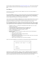
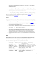
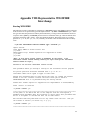
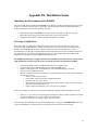
After a few seconds, OpenWindows will automatically load and present the login window shown below:
Login as [telescope] (where telescope is "2meter" or "4meter" as appropriate) with the current password
posted on the workstation terminal. The WILDFIRE system will then load automatically, resulting in a
terminal screen layout approximately like Fig. 5 below; the dashed window labeled Instrument Status will
appear in the approximate position shown only after the instrument microcode has been loaded.
16
Normal WILDFIRE Startup
The Windows
Once the environment has been set to WILDFIRE by obsinit, it will remain in that state, even if it is
necessary to reboot the instrument computer for any reason. There should be no reason to execute
obsinit more than once during a run. If a reboot is required, the login procedure in the window
displayed above will automatically bring up the WILDFIRE windows.
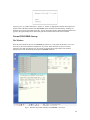
Fig. 5 -Windows layout after initiation of WILDFIRE – left screen
A brief description of the windows follows:
•
•
•
1. Instrument Control -- This is the window for entering all commands controlling the instrument
or telescope. It will initially have a "[instrument computer]" prompt, and a "%" prompt when the
instrument microcode is running.
2. IRAF XGTERM -- This window is used for IRAF commands for analysis of data or for shell
commands such as creating directories, moving, or archiving data.
3. Instrument Status -- Once the instrument microcode has been loaded, this window will appear.
Instrument, voltage, detector status commands in the Instrument Control window will output here.
The existence of this window is a diagnostic of WILDFIRE, as a system crash will often close it.
17
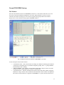
Menu buttons for lapis VNC, Ximtool, and DS9:
•
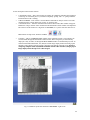
4. Display -- This is an XIMTOOL/DS9 window on the right hand sapphire screen that may be
accessed either through the Instrument Control window, where images may be automatically
displayed as they are taken, or through the IRAF XTERM window via the IRAF display task. To
switch between DS9 and Ximtool, exit (kill) the current image display window and bring up the
alternative image display from the sapphire menu bar at the bottom of the left screen. Owing to
competing computer traffic and limited bandwidth with the older machines, bringing up an
image display inside the lapis VNC is discouraged.
Fig. 5 -Windows layout after initiation of WILDFIRE – right screen
18
Bringing up WILDFIRE
There are three basic steps in the complete startup of WILDFIRE: hardware initialization; starting
WILDFIRE; instrument initialization. The procedure below will go through all three steps, as would be
necessary on the first night the instrument is on the telescope.
Hardware Initialization
This procedure establishes the link between the DSP box and the computer, by rebooting the observer's
SUN workstation with the SQIID power off. The obsinit procedure for the first night of an SQIID block
(described above) includes these steps.
HISTORIC NOTE: The startup script for WILDFIRE was simplified significantly in 1999. The microcode
will be loaded automatically and the bias for SQIID set to the default values. The dialog during a typical
WILDFIRE/SQIID initialization is recorded in Appendix IX.
Starting WILDFIRE
HISTORIC NOTE: The startup script for WILDFIRE has been simplified significantly in 1999. The
microcode will be loaded automatically and the bias for SQIID set to the default values. The dialog during
a typical WILDFIRE/SQIID initialization is recorded in Appendix IX.
At this point, the windows should be present as in Fig. 5. Go to the Instrument Control Window and enter:
startwf
This will lead you through an interactive startup procedure. READ THE QUESTIONS CAREFULLY;
simply entering [cr] will return the default, which may not be appropriate. For the full startup, the replies
are:
•
•
•
•
•
•
•
Has the WFire DSP box power been off for any reason since the last time you ran startwf or restart
(if unsure try 'n')? [n] y
Was the computer rebooted with the instrument power off? [n] y (a short initialization process
follows)
Has the instrument power been off since the last time you ran startwf or restart? [n] y
Is the instrument power on now? [n] (you will be prompted to turn on the instrument power)
[cr]
Which instrument are you using (enter PHOENIX, IRIM, CRSP, SQIID, etc.)? SQIID (the
instrument name may now be in either capital or lowercase letters!)
Do you want windows? [y] [cr]
Do you want to save in IRAF format? [n] (default is FITS). [cr]
At this point, the transputer nodes will bootstrap, and four .tld files will load. Eventually (when the startup
script automatically executes "setup sqiid") you will see messages regarding the downloading of the
microcode, setting of 4 values of VddCl1 (-1.3), VddCl2 (-3.5), VggCl1 (-4.9), VggCl2 (-2.8), and Vset (1.8). When this is completed, the final message will appear:
•
Do you want to activate the array? (y or [n]) y
You will see messages reporting 4 biases being set, followed by:
19
•
The arrays are now activated
If you want to use a different parameter file than the default "sqiid" parameter file that was executed by the
startup script, you can enter "puse parameter_filename" at this time.
SQIID is now ready for operation.
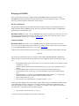
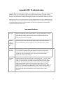
Problems?
If difficulties are encountered in startup, entering trouble in any of the windows (except the Instrument
Control) will open a troubleshooting diagnostic, listing symptoms and possible solutions. However, most
problems occur during the initial installation, and are often hardware related. The most common problems
are listed below:
Note: Detailed instructions for recovering WILDFIRE operation are contained in Appendix III.
red LED(s) in
DCU
Bad fiber connection. With the instrument power on, the green LED in the DCU
should be on, and the two red LEDs off. If either or both red LEDs is lit, there is a
fiber problem which must be repaired. A similar set of LEDs in the DSP box can
diagnose fiber problems at that end.
halt after
"Configuring
C004"
Bad fiber optic connection (see above). Even if red LEDs are off, one or more fibers
may have poor throughput, which must be measured. Power supplies may be
connected improperly. Check that the analog connector goes to "CCD Power" and
not "PS-10 Power" on the telescope.
halt after
"bootstrapping
node 100"
Bad fiber optic connection (see above). C004 may not be configured and a full
startup may be necessary (DSP cycle, reboot, startwf).
"error #16
(cannot open
link)"
System stuck in funny state. Full startup may be required. If that does not help,
check for proper power connection and fiber throughput.
"cannot read
telescope status"
Link to TCP computer is down. This is usually solved by rebooting the TCP
computer. WILDFIRE will still work, but cannot move telescope or retrieve
telescope status information for header.
In addition, comments, suggestions, and descriptions of persistent problems should be emailed to
wfire@lemming, which has been set up as an equivalent to service for WILDFIRE instrumentation.
Parameter Sets
"parameter sets" are used to control the attributes of data acquisition. A listing of the parameters is given
below. Because the data are saved directly as IRAF images, note that parameters include not only
20
observation-specific items such as integration time, but archiving items such as the IRAF filename and the
header and pixel directories.
Observing Parameters
title
coadds *
lnrs
pics
integration_time *
filename
header_dir
pixel_dir
mode
nextpic
ucode
display
ra
dec
epoch
offset
imag_typ
airmass
comment
im_list
save
archive
IRAF header title
number of coadded integrations per image
number of low noise reads (1 for SQIID)
number of pictures per observation
integration time (seconds)
IRAF filename
image header directory
pixel file directory
process mode [stare, sep, hphot]
picture index
microcode
channels to display (j, h, k, or l for SQIID)
RA of object #
DEC of object #
epoch of object #
observation offset
type of observation [object,dark,flat..]
airmass of object #
comment
filename of image list
channels to be saved to disk ([j h k l] or subset for SQIID)
channels to be archived ([j h k l] or subset for SQIID)
* WARNING: Use 'set-time' to set coadds and integration time rather than responding to the
individual 'coadds' and 'integration_time' queries from 'ask'.
In general, the parameters fall into three categories:
•
•
•
those which one may wish to modify for an observation (integration time, title, ...)
those which one might want to change on an infrequent basis (comment, header directory, ...)
those which are never changed (mode, display) or are automatically entered into the header
through the link to the TCS computer (marked with # above).
The command ped will open an editing session on the current parameter set, listing each parameter in turn
and prompting for new entry ([cr] returns the present value). At the beginning of a run, one should execute
ped and set up those parameters falling into categories 2 and 3 above. NOTE: One cannot specify a nonexistent header or pixel directory in ped; it is necessary to go to the IRAF XTERM window and create
those directories first! Since it is cumbersome to go through the entire parameter list for each observation,
there is a command eask, which runs through the entire parameter list, permitting the observer to specify
which parameters should be queried at the beginning of each observation. Entering "la" for a
parameter selects it for the "observation menu"; entering "l" excludes it. NOTE: The "up arrow" key may
be used to back up through the ped list if one wishes to change a previously entered parameter.
When this is complete, save the parameter set with the command psave [filename]. This will save
both the edited parameter set and the menu selected by eask in the file '[filename].par'. Should the system
crash, this information may be retrieved by the command puse [filename]. Should major changes be
21
made to the parameter file, such as change of header or pixel directory (say on another night of the run), it
is a good idea to psave the updated file so it, and not the previous version, will be recovered by puse.
Observing Words
The basic observation is initiated by the command observe. The system will print on the screen, one at
time, those parameters selected by eask, and the current value [], prompting for entry of a new value or
[cr], which will enter the current value. The command go will begin an observation, but will use the
current values for the parameters (except the picture index, which will be automatically incremented). The
command movie will begin a loop consisting of an observation (using the current parameters!) and a
display; this may be terminated with end at any time. The observation in progress will be completed and
displayed. Movie observations are stored on disk! This is unfortunately necessary to prevent orphaned
pixel files from filling up the disk. A recommended procedure is to include the 'filename' parameter in the
ask menu and change to a dummy filename at the beginning of a movie. When returning to data taking,
one may reset the filename to that used for the data. If one wishes to retain continuity in the index number,
it is also necessary to reset 'nextpic' to the value before the movie observations. Keep good logs!!
The ask command will cycle through the selected parameters, prompting for changes, just as with obs,
but will NOT begin an observation. This command is useful for checking parameters, and is essential
before executing movie, which will use the parameters for the previous observation, even if it were 600s
in length. The combination of ask and go is a perhaps preferable alternative to observe.
One may abort an observation (such as an unintentional 600s movie) by entering abort in the Instrument
Control window; the system should respond by acknowledging the abort and the observation should
terminate gracefully in a few seconds. This can sometimes turn off the display and save operations, so it
is advisable to re-enter save j h k l (or whichever subset you have been using) and display k (or
whichever channel you have been using after an abort.
TCL Dithering Scripts and IRAF Tasks
The user interface is written in the Tool Command Language (tcl), which is well-suited to the construction
of scripts for data taking. Scripts are a powerful tool for executing a sequence of tcl commands, including
telescope motions, instrument motor commands, and observations, as a single executable program. Even
for those who are not veteran programmers (most of us), simple scripts are fairly easy to construct. Scripts
are highly recommended for spatial sampling (dithering) and linearity calibrations. The best recipe for
starting out is to copy an existing script to a new file and then edit that file as desired. The first line of the
script file contains the base name of the script file ("proc "), and must be edited to reflect the new name of a
script created in this manner. Before the initial use of a script (or after a system restart), it must be
identified as an executable in the Instrument Control window, using the full path name of the file; e.g.,
source
/data2/2meter/tclSamples/[scriptname].tcl
To execute the script, enter the base name [scriptname] as a command in the Instrument Control
window. A sample script is given in Appendix IV.
Scripts may be found in directory "tclSamples" under the "[telescope]" directory, as in the path above, and
also in /usr/wfire/tcl. This latter path is the system response to query pwd in the Instrument Control
window. When creating a custom script, please copy a system script into an observer directory and then
rename and modify it, to avoid confusion.
Scripts copied into the user home script directory (/data2/2meter/wfire at the 2.1-m and /data2/4meter/wfire
at the 4-m) and sourced can be marked for automatic inclusion in subsequent invocations of "startwf"
by entering "mkIndx".
22
For the more sophisticated (or daring) observer, a TCL manual is available. WILDFIRE presently uses
TCL version 6.7 and properly written code should run with no special limitations. Please note we will not
debug or otherwise support user code, nor will user supplied TCL routines be saved within WILDFIRE
from one observing run to the next.
The following WILDFIRE default scripts are useful for various observing programs, and as templates for
user-constructed modification. They are initiated by entering the script name as a command, and going
through a series of interactive queries to set internal parameters. Alternatively, several have command line
versions for faster use. These are default scripts which do not require sourcing.
•
•
•
do_standard : takes 5 observations in a fixed spatial pattern using the current parameter set for
integration time, filename, etc. First observation is at the current position, next four are in a square
centered on the first position; routine then repositions the telescope to the starting position and
quits. You are prompted for the side of the square in arcseconds. Verify that your objects do not
systematically land on bad pixels; if they do, change the initial point or offset value. Note: script
updates the telescope information in the image header on the first image (using "tcp_on") and then
turns header updates of telescope information off (using "tcp_off") for the rest of the sequence.
After the last image is taken, telescope header updating is restored (using "tcp_on").
do_standard_on : same as do_standard, but updates telescope information in the image header
for each image in the sequence.
do_field : observe an M x N (RA x Dec) spatial grid of positions, with fixed separation E-W
and N-S, using the current parameter set. Returns to starting point when completed. The grid is
centered on the starting position. Prompts for the number of grid positions E-W, the number N-S,
and the grid separation in arcsec. Observations begin at NE corner, proceeding W and S a row at a
time. The command line version is
do_fld [ewnum] [nsnum] [gridsep]
•
do_dither : observe an M x N (RA x Dec) spatial grid of dithered pairs, with fixed separation
EW and NS, using the current parameter set. Two frames slightly offset (dithered) EW are taken at
each grid location. Grid is centered on the starting position, and returns here when done. Prompts
for the number of grid positions E-W, number N-S, grid separation in arcsec, and E-W dither in
arcsec. Observations begin at NE corner and proceed W and S a row at a time. The command line
version is
do_dthr [ewnum] [nsnum] [gridsep] [dither]
•
do_pair : take a pair of spatially offset images and return to the first position. This is
particularly useful to confirm the location of a faint object, which can be determined by
subtracting the two frames. Prompts for the offset vector in arcsec, and must receive two values:
RA first, then Dec, separated by a space. Use "+" to specify E and N, "-" for W and S. The
command line version is
pair [ewsep] [nssep]
•
do_9raster : observe a 3 x 3 spatial grid of source and dithered offset sky data pairs, in the
sequence source-sky-sky-source. The sky position is dithered between each sky frame so that
objects in the sky field are not position locked relative to the source frames. The data are taken in
an order which minimizes telescope motions. Note: script updates the telescope information in the
image header on the first image (using "tcp_on") and then turns header updates of telescope
information off (using "tcp_off") for the rest of the sequence. After the last image is taken,
telescope header updating is restored (using "tcp_on"). Prompts for grid separation, sky dither
vector (small motion: must have two values) and sky offset vector (large motion: also two values),
23
all in arcsec. The vectors are ordered (RA, Dec) with "+" for E and N, "-" for W and S. The
command line version is
do_9rstr [gridsep] [ewdither] [nsdither] [ewsky] [nssky]
•
do_9raster_on : same as do_9raster, but updates telescope information in the image header
for each image in the sequence. The command line version is
do_9rstr_on [gridsep] [ewdither] [nsdither] [ewsky] [nssky]
Refer to the Appendices for listings of WILDFIRE and SQIID commands (Appendix II) and
troubleshooting procedures (Appendix III).
tmove
Michael Merrill's provisional IRAF script tmove may be used for centering stars on the array, using an
image displayed in the ximtool window. Because this is not yet a standard IRAF task, it will probably have
to be manually installed for an observing run.
•
•
•
If the file "tmove.cl" is not found in the [telescope] or [tclSamples] directory, download it.
The script is defaulted for SQIID at the 2.1-m. If you are at the 4-m, it will be necessary to edit the
telescope string parameter in the file "tmove.cl".
In the data directory, identify the task to IRAF by entering the full path name of the file; e.g,
task tmove
•
•
=
/data1/4meter/tmove.cl
To execute, enter tmove. You will be prompted to put the cursor on the star in the ximtool
display. Entering c will compute the offset to the center (256:256) of the array; entering
[spacebar] will prompt you to move the cursor to the target position and enter another
[spacebar]. In either case, the computed offsets will be displayed in the IRAF window
The displayed offset command "toffset..." may be pasted directly into the Instrument Control
window.
idisp
Michael Merrill's provisional IRAF script idisp may be used to display sky-subtracted images in the
ximtool window. Because this is not yet a standard IRAF task, it will probably have to be manually
installed for an observing run. Note: type upsqiid at the cl prompt if idisp is undefined.
The script is defaulted for SQIID at the 2.1-m. The parameters are as follows:
first_image = "test010j.fits" First image in sequentially
numbered images
sky_image = "-1"
Name or sequential number of sky frame
(frame = 2)
Display frame #
(number_id = "000")
image number template results image? 000
(listid = "/tmp/list") name of wildfire system image list?
(dolast = no)
Repeat for most recent image
(dostats = yes)
Perform imstats?
(statsec = "[100:400,100:400]") Image section for calculating
statistics
(lthreshold = INDEF)
Lower threshold for exclusion in
statistics
24
(hthreshold = INDEF)
(imsave = no)
(saveid = "dpr_")
(zscale = yes)
(ztrans = "linear")
(z1 = 0.)
(z2 = 1000.)
•
•
•
•
•
Upper threshold for exclusion in
statistics
Save difference of each pair?
String prepended to object name
automatic zcale on each frame?
intensity transform: log|linear|none
minimum intensity
maximum intensity
To execute, enter idisp. You will be prompted to put the name of the image you want skysubtracted and the identity of the sky image. The sky image can either be the name of another
image, the special entry "prev" which indicates the previous image, or an ordinal number offset (+
or -) from the image in the first entry.
Image statisitics for the two frames and their difference will be also be displayed.
If you set "dolast=yes" (either using the IRAF epar or appending "dolast+" to the command line),
idisp will display the sky-subtracted result from the most recent image using the filename and
channel parts of the first entry.
If you want to save substracted image (e.g., so you can use imexam on it), set imsave=yes (either
using the IRAF epar or appending imsave+ to the command line).
The "z" parameters are the same as those in the "display" task.
25
7. Observing Practices
The installation of the instrument and cables will be handled before the beginning of the run by the
mountain technical staff and are not of concern to the user. The SQIID Reference Manual provides
coverage of the details of installation and setup for those who are interested. SQIID remains on the
telescope (with power on, under normal circumstances) for the entire observing run.
Getting Started
After SQIID is installed on the telescope, go through the WILDFIRE startup procedure outlined previously.
Once the system is operational and the detector activated, check the detector and temperature status with
status s and compare with the nominal values below:
status s
SQIID Base Status Display
18:11:29
H detector
K detector
J detector
L detector
Integ time (secs) =
0.855
0.855
0.855
0.185
CoAdds
=
1
1
1
1x1
Lnrs
=
1
1
1
1
Number of Pics
=
1
Detector Temp
=
29.81K
30.68K
29.81K
30.68K
Det Heat Pwr (mw) =
129.39
56.15
146.48
75.68
Observation Settings Mode
=
stare stare stare stare
File name = "test%03d%s" Index = 95
Space Available
Header Dir = "/data2/2meter"
3046308kb
Pixel Dir = "/data2/2meter/pixels"
3046308kb
----------------------------------------------------------------------Housekeeping information is reported via status screens. Additional status screens for SQIID are:
status t
SQIID Temperature Display
H detector
K detector
J detector
L detector
Detector Temp
=
29.81K
30.68K
29.81K
30.68K
Det Heat Pwr (mw) =
136.72
61.03
153.81
78.12
Bench 0 (North)
=
40.69K
Bench 1 (South)
=
39.61K
Wheel
=
46.29K
Sieve Plate
=
18.15K
Cold Hd A 1st St =
32.17K
Cold Hd B 1st St
=
32.34K
Cold Hd A 2nd St =
11.53K
Cold Hd B 2nd St
=
13.47K
----------------------------------------------------------------------status v
VSet
ISet
VDet
VDesUR
BOK
VddUC
SQIID PRCD Voltage Status Display
H detector
K detector
J detector
=
-1.783
-1.790
-1.779
=
0.266
0.297
0.257
=
-2.897
-2.815
-2.926
=
-5.579
-5.589
-5.583
=
-2.896
-2.815
-2.925
=
-3.475
-3.497
-3.488
L detector
-1.803
0.322
-2.701
-5.587
-2.698
-3.489
26
VddOut
=
-0.986
-0.992
-0.989
-0.991
VddCl1
=
-1.315
-1.319
-1.303
-1.303
VddCl2
=
-3.545
-3.560
-3.517
-3.514
VggCl1
=
-4.867
-4.886
-4.861
-4.908
VggCl2
=
-2.773
-2.786
-2.769
-2.791
Vp
=
-0.489
-0.494
-0.494
-0.493
VnRow
=
-6.207
-6.186
-6.179
-6.177
VnCol
=
-3.988
-3.993
-3.987
-3.987
VDesLr
=
-0.494
-0.489
-0.497
-0.494
VRowOn
=
-5.985
-5.983
-5.985
-6.002
VRowOff
=
-0.685
-0.694
-0.695
-0.688
VRstOn
=
-5.971
-5.989
-5.973
-5.970
VRstOff
=
-2.991
-2.991
-2.989
-2.991
----------------------------------------------------------------------status 3
SQIID Power supply Voltage Display
Gnd Ref H/K Box
=
-0.097
Vcc1 H/K Box
=
4.740
Vcc2 H/K Box
=
4.750
PRCD Card
+5v Sup
+15v Sup
-15v Sup
+7v VRef
-7v VRef
H detector
=
4.951
=
14.866
=
-15.100
=
6.914
=
-6.909
Gnd Ref J/L Box
Vcc1 J/L Box
Vcc2 J/L Box
K detector
4.951
14.906
-15.198
6.921
-6.914
=
=
=
J detector
4.945
14.893
-15.078
6.911
-6.897
-0.105
4.699
4.706
L detector
4.944
14.922
-15.250
6.906
-6.897
PA Cards
+5v Sup
+15v Sup
-15v Sup
+5v VRef
-5v VRef
H detector
K detector
J detector
L detector
=
4.952
4.950
4.944
4.947
=
14.968
14.923
14.960
14.804
=
-15.188
-15.062
-15.295
-15.131
=
5.002
5.001
4.992
4.992
=
-4.986
-4.986
-4.980
-4.978
H detector
K detector
J detector
L detector
VOff1
=
0.675
0.675
0.669
0.669
VOff2
=
0.678
0.677
0.668
0.672
-----------------------------------------------------------------------
27
Techniques
Focus
SQIID acts as its own acquisition camera. Open up and acquire a star in SQIID. Stars with K magnitude
fainter than 6 are OK for initial acquisition, but stars fainter than K = 9 are necessary to avoid saturation for
final focus adjustments. [Note: When SQIID is first installed, it is best to start with unambiguous stars to
verify initial telescope pointing. Stars brighter than K = 3 are best for this purpose.] Use individual "go"
exposures (because of the 40 second delay movie can be confusing), to get the star within the central
region of the array. Choose a wavelength channel for determining focus (preferably K which suffers least
from seeing) and stick with it through the run to avoid confusion. The four SQIID channels are near
parfocal, but differences in sensitivity to seeing and slight differences in image quality away from focus can
be confusing if you switch back and forth. Once the star is found, move the telescope until it is centered.
and focus the telescope, resetting display limits and integration time as necessary, until a tight image is
obtained. For optimizing focus, it is best to obtain single images, using observe or go, and analyze the
image quality with the IRAF task imexam using the ‘r’ command. Remember that it may be
necessary to relocate the beam when moving to a new object.
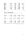
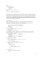
An example of excellent focus (K channel, 1.0 sec) can be seen in Figure 6. Note that the star appears to be
positioned at the center of a pixel. Since the geometric quality of the optics on the order of 80% flux within
two pixels radius and the profile fitting algorithms stall near 1.5 pixels, this is as good as it gets. FWHM of
1.8-2.0 is more typical. (The rightmost three values at the bottom of the profile image are the FWM from
different profile fitting algorithms.) Naturally, longer exposures will have somewhat broader profiles.
Fig. 6 - Radial image profile for excellent short exposure focus: 1 sec at K
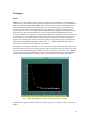
Stars that are too bright will tend to be either flat topped or possibly even contain a central void as seen in
Figure 7.
28
Fig. 7 - Radial image profile of a star that is too bright
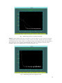
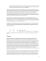
NOTE: It is likely that the single pixel events (that occur at the roughly once per second) are in response
to alpha particles from the anti-reflection coating of the last lens surface. We have since discovered that
thorium fluoride is the coating of choice for producing durable wide bandpass coatings. The magnitude of
these single pixel events is typically 3000-5000 ADU with of order 5% leakage into the four nearest
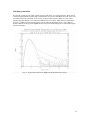
neighbors. Figure 8 is the radial profile for a typical single pixel event.
Fig. 8 - Radial image profile of a single pixel event
29
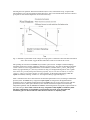
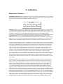
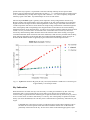
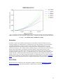
At the 2.1m telescope focus is a simple function of temperature. Best focus as a function of temperature
shifts as deltaF/deltaT = 0.025 per degree K with a focus at 5.10 for 8K. After the temperature of the
telescope structure stabilizes (it varies rapidly for roughly an hour after opening), the relationship provides
an accurate estimate for best focus, which generally shifts towards smaller values as the night progresses.
Pick a temperature (such as the secondary or the front surface of the primary) and monitor that temperature
to adjust focus. It appears that best focus was a tolerance of at least +/- 0.01 focus units. It is useful to note
that there appears to be no backlash in the IR secondary. At the 4m telescope, nominal focus is -7300 with
an as yet undetermined temperature dependence.
Fig. 9 - Focus at the 2.1m telescope
Performance Checks
SQIID will be installed and checked out at the start of each observing run by a competent and cheerful
support scientist. Users may confirm continued proper operation during their run with software
interrogation and by comparing dark and flatfield frames against "standard" frames.
Detector status and temperature information is displayed with the word status s; it is also automatically
updated at the beginning of an observation. Standard values for the default SQIID configuration are
displayed above. The cryogen temperature readouts are displayed as temperature based on a generic
relationship between voltage at constant current and temperature.
The heater power may vary somewhat around the typical value given. However, a significant and persistent
departure from this value may indicate the dewar is losing its vacuum (going "soft") or that the Closed
Cycle Cooler System is losing efficiency. If this is suspected, contact the instrument support scientist.
Finally, sky- or dark-subtracted frames may occasionally show a dark (or light) circular artifact about 30
pixels wide. This “Phobos effect” (see Fig. 10) results from a region of lower signal in one of the frames,
and can appear as a positive or negative image anywhere on the array. This occurs very infrequently, and is
apparently a crystal relaxation phenomenon in response to the array being warmed after having been too
cold (below 25K). This can happen over a span of a few hours when the SQIID electronics have just been
powered on after they have been off for an extended period. (The array heater power is controlled by the
same power supply as the electronics.)
30
Fig. 10 - "Phobos effect" (dark circular patch at lower right)
31
8. Calibration
Responsivity Calibration
Atmospheric extinction must be calibrated by observations of either a standard star as close as possible to
the same zenith distance used for the object or a series of stars that span the range in zenith distance for the
observation. Typical extinction for SQIID is summarized in Table 9.
Table 9. Estimated SQIID Extinction in
mag/airmass
J
H
K
PAH
0.15
+0.06
+0.08
TBD
Flatfield exposures are necessary to calibrate the pixel-to-pixel gain variations in the array and the effects
of the illumination of the array by the internal optics. The system response is stable and is very flat across
the arrays, with a slight intrinsic column to column modulation of +/- a few percent (owing to relative array
orientations, columns may have either NS or EW orientations in the saved and displayed images).
Consequently, the flatfield for each channel should be stable at the percent level under normal illumination
and global flatfields can be constructed which are viable for extended periods of time. Since direct
illumination of the array is possible (remember that the secondary mirror is undersized), observations near
bright sources, such as the moon, which have atypical illumination, should not be use to determine global
flatfields. Observations during twilight will also have illumination atypical of nighttime observations.
Because sky flats provide the same array illumination as real observations, they are preferable in principle
to dome flats using the White Spot. It is, nonetheless, a good idea to obtain dome flats as a backup. If one is
observing in a sufficiently sparse star field, one may use the same set of observations for the object, sky,
and flatfield. Because the sky flats will include the array dark current, it is necessary to obtain separate
"dark" observations for subtraction from the sky observations. Unfortunately, what constitutes a "dark"
frame for creating flats is ill-determined due to the "memory" effect which accumulates in time. For
example, a series of observations in the dark filter immediately following sky (or dome) flat observations
will show a monotonic decrease in mean value as the "memory" of the relatively bright preceding
observations decays over 5 to 10 integration times. By the same token, a series of dome flats following dark
or low-background observations will show a monotonic increase in mean value as the "memory" of the
higher flux observations accumulates. One possible approach is to take a larger number of dome flat or
dark observations and reject those early in the series, when the change in value from one frame to the next
is the greatest.
Should one decide to obtain "dome flats", it is recommended that one take exposures when the dome is
dark, to minimize the ambient radiation at J and H. At the 2.1-m and 4-m telescopes, the dome screen is
illuminated by lamps mounted on the telescope top ring. (The 4-m telescope is positioned by mountain
technical staff.) Darkening the dome may require waiting until visitor hours end at 1600 hr. The lamp
controls at these telescopes are on the LTO console. One should obtain a relatively large number (7 or
more) of flatfield images for post-processing within IRAF, where floating point arithmetic and sigmaclipping or median combining are possible (the latter to eliminate noise artifacts which may appear in a
single observation). Since the illumination level differs markedly at J, H, K and PAH, one should anticipate
taking data at several settings of the lamps. Within the K and PAH bands, one will be dominated by the
thermal emission from the dome screen, and at the PAH band, the lamps are not necessary. Dark current
and residual illumination subtraction require obtaining an identical series of observations with the flatfield
lights off (for J,H,K) or the dark slide in the beam (PAH). After subtraction of the "off" or "dark" frame,
normalization (using, for example the IRAF 'response' task) and median combining of these observations
should eliminate noise spikes or systematic features in the spectra. To stay within the relatively linear
32
portion of the array response, it is preferable to turn down the lamp intensity and use exposure times
relatively long in comparison to the readout time of 0.84s (e.g., 3 - 5 s). Keeping the flux at a modest signal
level (< 5000 ADU) may also help in this regard; with a read noise ~ 35 e, one is completely background
limited by signals > 500 ADU. Try flatfield lamps set at low 10 at the 2meter.
The time-dependent dark signal is generally small compared to the sky background for all four arrays.
However, higher-order spatial features, such as the gradient on one side of the H channel, are significantly
brighter and cannot be neglected when contructing flatfields. "Dark" images contain both static and time
variable components with diverse causes that obviate simple scaling of dark frames to alternate integration
times. Consequently darks corresponding to the integration times for data that will be used for defining
flatfield and linearity issues should be taken. A sequence of 9 exposures should be sufficient. Since the dark
current is so low, you will be able to see transient events, such as those due to cosmic rays that can be
removed by median filtering. Darks should be taken in the afternoon and/or in the morning. Closing the
cold internal darkslide (hand crank on the side of the instrument) is both necessary and sufficient for taking
darks. The time dependence of the median dark current within [100:400,100:400] is shown in Figure 11.
Note that the H channel exhibits an apparently negative dark current at short integration times.
Fig. 11 - SQIID dark current for H (green), K (red), and J (blue) Channels at 700mv bias. Conversion gain
is approximately 11 electrons per ADU.
Sky Subtraction
While the detectors are stable, the sky is not necessarily so. Under good conditions, sky flux varies only
with airmass and at a given position the sky can be stable over an hour or more. Naturally sky flux
increases when you get near the moon. When airglow is high and variable, the sky at H can vary by a factor
of two over the course of an hour, while the sky at J varies by 40%. Consequently it is prudent to monitor
the sky (use imstat inside IRAF) to be sure that you have sufficient data to perform sky subtraction on your
targets.
CAUTION: One cannot expect to simply co-add observations of faint surface brightness sources
and allow the off-source portion of the observations within the detector FOV to determine the
presumably constant level of the sky. At some level, defects in the flatfield (pupil ghosts, object
33
ghosts, or whatever) dominate the accuracy of the results. This deficiency is typically overcome by
subtracting off-source observations of the sky, then flatfielding the differences. This improves the
accuracy of the detected signal by at least an order of magnitude.
In the IR (even at JHK) observations of all but the brightest stars (9 mag) are background limited so that
typical diffuse targets (such as galaxies) are seen at very low contrast in individual frames. As noted above,
the sky background is constantly changing (slowly with airmass and on slow to moderately rapid timescales
with sky emission) so that the contrast varies as a function of time. Since observations are ultimately
limited by inadequacies in the flatfield, one cannot simply co-add such observations and obtain a
meaningful result; median filtering such data merely selects the middle frame. (For example, as the contrast
varies the illumination pattern on the array also varies since the relative mix of radiation seen through the
telescope optics and that seen directly past the secondary changes.)
One must devote a comparable amount of time off-source, intermixed throughout the on-source
observations, to provide sky frames; subtracting sky frames on a pixel by pixel basis reduces the contrast
problem and allows one to successfully co-add data taken over a long interval of time. When the targets are
much smaller than the array, one can accomplish this sky subtraction by moving the target around the array
and in effect taking the sky and source data at the same time.
GHOSTING - Each channel has its ghost, whose position is opposite the optic axis from its parent bright
star. Only saturated stars are bright enough to clearly show their ghost, which is out-of-focus, covering
about 25% of the chip. The out-of-focus ghosts that lie opposite the optic axis from the primary have the
following characteristics:
J
90
5.5
H
108
6.3
K
56
5.5
pixels diameter
difference in integrated flux in magnitudes
In addition, the J channel has an in-focus ghost located 36.5 pixels east of its parent and 5.4 magnitudes
fainter.
Linearity
When a pixel is reset, the voltage difference (bias) between the pixel and detector substrate creates a
depletion region that acts as a potential well for the collection of (mostly) photo-generated carriers.
Electrically, one may consider this potential well as a capacitor. As charge accumulates in the pixel, the
depletion region fills in, increasing its capacitance and that of the entire pixel node. Changes the gain of the
system, resulting in a sub-linear voltage-charge relationship, which quickly rolls off (saturates) when the
pixel voltage reaches that of the detector substrate (zero bias). Technically, a pixel will continue to
accumulate charge even into forward bias, but its response by that time will be significantly nonlinear. As a
direct consequence, pixel response departs from linearity in a predictable fashion for accumulated signals
above a device-specific level. Since the total capacitance (which determines system gain) is the sum of the
distributed (non-varying) capacitance of the system and the (variable) capacitance at each detector node,
the degree of non-linearity is a function of the ratio of nodal to total capacitance. Since key pixel
parameters such as quantum efficiency are very uniform, the linearity appears to be a global property of the
array rather than pixel specific.
Increasing the bias on a pixel will not only increase the depth of the potential well, but by decreasing the
capacitance of the depletion region in relation to parallel components of the node capacitance, will result in
a more linear voltage-charge relation. As a result, a bias increase from 0.6 to 0.8 volts will effectively
double the charge capacity of the pixel. This comes, however, at a significant cost in dark current, which
increases dramatically with bias. Therefore, we recommend a bias of 0.6v for JH, 0.7 for K, and 0.9v for
34
high-background (L band) observations, where the increased dark current is not important. These are the
default bias values for SQIID.
In the following discussion, observed (output) values have not been corrected for the unseen charge
collected during delay between biasing the detectors (reset) and the first (non-destructive) read of the bias.
A second (non-destructive) read is taken an integration time later. Only the difference between reads is
output. In detail, the global reset mode used to operate SQIID resets all the pixels at the same time and then
performs a non-destructive read of the array. The first pixel is read out shortly after the global reset and the
last pixel is read out 0.61 sec after the global reset. The charge accumulated at the time of the position
dependent first read is "lost", since its value does not get reflected in the difference. Hence, the reported
signal is always less than the total signal on the array at the time of the second read. At short integration
times and high rates of photon arrival (bright stars and/or high background), this unreported charge can lead
to a significant underestimate of the signal outside the scope of the usual linearity correction. The unseen
charge can be accurately estimated (apart from noise issues) on the basis of the timing, but since the
amount of unseen charge is position dependent, one is better off not "going there"! Ideally, the data fit are
always within the regime where this correction for unseen charge was small. This is not the case, for
example, when doing 0.84 sec integrations on standards!
One normally expresses the departure from linearity in terms of the relative error (input-observed) or the
normalized relative error (input-observed)/observed for each array and fits these data to an appropriate
mathematical model. For SQIID, the model fitted function for the relative error is:
ym[x] = a(1) * x**2 + a(2) * x**3
where ym = relative error = (input - observed)
x = observed (adu)
The fit is valid for values < Xmax. For values beyond Xmax, the array is rapidly approaching saturation.
The fitted parameters for each channel are summarized in Table 10 and the fitted linearity is plotted in
Figure 12. A new array was installed in the H channel in February 2002.
Valid from
Channel(bias)
a(1)
a(2)
Xmax(ADU)
Data date
Jun 2000
Ks (700mv)
6.4864e-7
4.4790e-10
16000
Apr 2003
Table 10. Fitted Linearity Coefficients
Jan 2005
Jan 2005
Mar 2002
H (700mv)
J (700mv)
H (600mv)
-1.3456e-8
1.2626e-6
8.4783e-7
6.1010e-10 2.9498e-10
6.8416e-10
16000
16000
16000
Apr 2003
Apr 2003
Apr 2003
Jun 2000
J (600mv)
1.2164e-6
4.7829e-10
16000
Apr 2003
Jun 2000
H (600mv)
4.5326e-6
4.8759e-10
14000
Apr 2001
35
Fig. 12 - Linearity Correction for SQIID. Relative error for H (green), K (red), and J (blue) Channels for
600mv and 700mv bias. Conversion gain is approximately 11 electrons per ADU. Prior to 2005, the JH bias
was 600mv As of January 2005, the JHK bias is 700mv.
.
Saturation
Eventually, a pixel will accumulate sufficient charge to forward bias it to the point where no more is
collected, resulting in a condition known as saturation. The reset-read-read address cycle used in double
correlated sampling (Fig. 4) results in a characteristic, but unusual, saturation behavior. For a given
integration time, the effect of increased flux is a steeper slope of the voltage-time curve. As the flux
increases, the voltage V2 will eventually saturate, while the voltage V1 will continue to increase because of
the time interval between the reset and the first read; the difference signal will thus decrease with
increasing flux. Finally, the detector will saturate in the short interval between the reset and first read,
resulting in identical values for V1 and V2, or a difference value of zero. Thus, the double-correlated signal
relation with flux is initially nearly linear, then increasingly nonlinear, and eventually decreasing to an
ultimate value of zero as one saturates. The A/D channels (2 for J,H,K and 8 for L) will saturate at slightly
different levels, resulting in an evident odd-even column pattern. These effects are evident in a Saturation
Image of the L band, in which the flux increases rapidly from the bottom to the top of the array.
Pixel Masks
Representative pixel masks for the J, H, K channels of SQIID are contained in Supplement 1: Channel
Specific Characteristics. These masks include the combined effects of intrinsically bad pixels and
instrumental vignetting.
36
9. Appendices
Appendix I: Telescope Checklist
Observing Platform / Cassegrain Cage Setup
The telescope and dome are operated by the Telescope Operator (nights) or the Technical Assistant (days).
Arrange schedules with them in advance for positioning for dome flats, and opening the telescope and
dome at the start of the night. The observer should:
•
Verify that the Instrument power supply is on (normally on). Switch is on the right (South) side
(near the top by the power cord) of the electronics box mounted on SQIID (Fig. 13). (If the sides
of the rocker show red, the switch is on.)
Fig. 13 Instrument Power Switch.
37
•
•
•
Check that the upper SQIID guider dark slide (fiberglass slide with aluminum pull tab at top of
telescope interface ("guider") on the South) is out. This is normally removed at the start of a run
but it may have been reinserted for added protection in response to high humidity/rain.
Check that the lower SQIID guider dark slide (Fig. 14) is out. The "stick shift" on the west of the
SQIID guider should be fully out. Pull it out firmly to engage the detent.
Check that the internal SQIID aperture wheel is open (except when actually obtaining darks).
Status is indicated by the lights at the hank crank on the North side of SQIID. Turn on the
indicator lights and follow the directions posted there. Turn off the indicator lights when you are
finished. The 3 positions (dark:red, polarizer:yellow, open:green) are equally spaced roughly 3031 turns apart. The hand crank can be used to move in either direction and the dark and open
stations are larger than the FOV.
Fig. 13 Cold Dark Slide hand crank and indicator
38
Computer Room Setup
•
Computer, Heurikon DSP (Fig. 16) power on (normally left on)
Fig. 16 Heurikon DSP Box
Control Room Setup
Inside the control room there are a number of tasks to attend to:
•
•
•
•
•
[2.1-m only]Turn on chopping secondary rack units, bottom to top, five in all. Push MOTOR ON,
SERVO ON buttons on drive modules (power must be on, even though one is not chopping). Be
sure to set both the X and the Y axis source selectors to EXT ANALOG position and dial in
OFFSETs for best collimated images as noted on the rack. The secondary should be left ON all the
time. For additional information, please refer to the on-line 2.1-m Chopping Secondary User's
Manual.
Prepare object list for entry into XOBJECT cache by LTO; alternatively, have LTO check at
earliest opportunity that coordinates sent by email are properly loaded.
[First SQIID night only] Execute obsinit on lapis to switch from ICE to WILDFIRE
environment; this should be done by support person.
If it is not already running, bring up WILDFIRE on the instrument terminal and activate detector.
Instrument power is controlled by the switch on the instrument located on the SQIID electronics
box near the power cord.
39
•
•
•
Create parameter set(s) as needed for observing with ped and eask and save with psave.
Create and source any custom observing scripts required.
Check that status s gives proper values.
SQIID is now ready to take data.
Calibration Data
Although sky flats are generally adequate for reducing SQIID observations, dome flats may be useful.
Dome flatfields may be done either in the afternoon before observing or in the morning. Remember that
you will need dark frames taken the same way (integration time and number of coadds) as your sky/dome
exposures to properly produce your sky flats. Since the temperature and operating conditions for SQIID are
highly stable by design, one should not have to repeat flatfields once they have been verified. In any case, it
may be desirable to take some short and long (30s) dark frames before the first night of observing to verify
performance.
•
•
Telescope focus set to nominal value for SQIID (approximately -5.20 at 2.1-m; -7300 at 4-m)
Dome flats:
o Dome and telescope positioned by TA/LTO to center of flatfield target
o Dome lights off; door to visitor gallery closed
o Turn on flatfield lamps; intensity controlled by buttons at LTO console
While all channels are exposed simultaneously, one may find different lamp settings are
required to be properly onscale at each channel. Flatfield series should be obtained for each
bandpass (J, H, K) used for observing, as each wavelength channel is serviced by its own
array. Two settings, one for J/H and one for K should suffice. The high background at L
band obviates dome flats - use sky L band flats instead Use an illumination level sufficient to
give approximately 5000 ADU in 2 s integration time. Higher signals in shorter integration times
may exacerbate nonlinearity effects. Read noise is sufficiently low that 200 ADU signal will be
background limited. Obtain 5 - 10 flats in each band desired for later median averaging. Turn
flatfield lights off and obtain an equal number of non-illuminated bias images at each setting.
•
•
Compare flatfield and dark current data with standard frames as check on array performance
Look at IRAF/FITS longheader to verify that telescope coordinate information is being acquired
Final Setup at Start of Night
Telescope Operator will do final dome and telescope checks and acquire stars, offset, etc. SQIID acts as its
own acquisition camera.
•
•
•
•
Acquire ephemeris star (K ~ 9 - 10)
Ensure telescope focus is near nominal value (5.20 at 2.1-m; -7500 at 4-m)
Acquire, center, and focus infrared image, resetting zs and integration time if necessary
When satisfied, zero telescope pointing
Observing Miscellany
Telescope motions are generally commanded from LTO terminal, although they can also be entered from
the observer's terminal. For programs demanding frequent motions, agree on a mutually compatible
40
protocol with the LTO. In the event of multiple observers, only one should serve as the communication link
to the LTO.
•
•
[2.1-m] The dome lower shutter must be raised to reach large airmasses (zenith distance < 62deg).
This takes about five minutes. Zenith distances < 30deg are inaccessible with the lower shutter up
The catwalk is off limits to observers, unless accompanied by the LTO. Check the weather from
the ground floor level
Control Room Shutdown
•
•
•
•
•
LTO will position and close up telescope and dome
[2.1-m]Leave chopping secondary rack powered up, except last night of block run
Save image data to tape, either by:
o wfits IRAF/FITS images to Exabyte or DAT
o tar FITS images to Exabyte or DAT
o wfits IRAF images to FITS files on disk and tar them to tape.
o ftp files to home computer
Enter work requests into service program through the LTO
Verify operational hours for LTO to enter into electronic observing log
Observing Platform / Cassegrain Cage Shutdown
•
•
•
Leave the Instrument power supply alone (normally on).
Close the lower SQIID guider dark slide. The "stick shift" on the west of the SQIID telescope
interface should be fully in.
Set the internal SQIID aperture wheel to dark. Status is indicated by the lights at the hank crank on
the North side of SQIID. Turn on the indicator lights and follow the directions posted. Turn off the
indicator lights when you are finished.
Computer Room Shutdown
•
•
Rewind and remove tape
Leave computer, instrument, and Heurikon DSP power ON at all times
41
Appendix II: WILDFIRE Command List for SQIID
SQIID image names follow the naming convention:
"filename"//"ch_id"//"XXX"//"image_extension" (e.g., n1_001j.fits)
where "filename" is an observer controlled parameter, "ch_id" is the approripate designator from the set "j
h k l", the number "XXX" is sequentially numbered (being automatically incremented for each exposure
until a new value is declared, either at a new object or new night) and "image_extension" is either ".fits" or
".imh" (depending on the saver setting declared at startup). If you correctly set 'oldirafname = yes' when
reading the data from tape, the image names will be restored to their original names and match the log
sheets.
A list of available commands within the WILDFIRE instrument control window is:
SYSTEM LEVEL
! commands
execute the commands in csh or run csh
? command
give help on a command
ed name
call up an editor on a proc
help name
display help for one of these topics
man name
display a man page for a given topic
progress 0
minimize diagnostic output during integrations (**node...)
source program
temporarily include tcl program within recognized system; need to
source again after powerup or go (full path name required)
DETECTOR
activate
activate the detector
deactivate
deactivate the detector
setup sqiid
set up the default SQIID voltages and prompt for activation. Alternative
42
parameter named parameter files can also be invoked via setup filename
?ucode
list array microcode currently in use (also in image header)
dl microcode_name
download specific array microcode
WILDFIRE
startwf
initiate bootstrapping and downloading of the WILDFIRE system
exit
deactivate the array and exit the WILDFIRE controller
trouble
open troubleshooting session (do NOT enter in Instrument Control
window)
hung
attempts to complete link protocol; used as part of the restart procedure
when WILDFIRE is hung (INSTRUMENT CONTROL window
unresponsive and data collection stalled); must be entered in Console
window
HOUSEKEEPING
newobserver
enter observer name and proposal ID for image header
status [|s|v|t|f]
display a status screen; (general status |s|; voltages|v|; temperatures|t|;
filters |f|)
longheaders [on|off]
will disable/enable house keeping data in the header
tcp_on
enable link to TCP for telescope status info and offsetting
tcp_off
disable link to TCP for telescope status info and offsetting
43
PARAMETER FILES
Note: a parameter has two attributes, its value and flags indicating whether the parameter and its
value should be displayed and/or queried when the ask or observe tasks are run.
lpar
list the names of the available parameter files
plist
list all the current parameters
psave filename
save the current parameter set (values and ask/display flags) to the named
parameter file
puse filename
load the named parameter file
ped
edit the current parameter file selected by puse asking all questions
regardless of query status
ask
prompt for the eask selected subset of parameters within the current
parameter set
eask
iterate through all the known parameters, allowing the user to specify
which parameters are queried and which are displayed. After each
question an "l" signifies display only; "a" signifies query; "la" will list
the current value (which may be selected by [cr]) or accept a new entry
44
ACCESSING INDIVIDUAL PARAMETERS
Note: many SQIID parameters have 4 values (one per channel) which are entered on the same line
separated by whitespace. The last argument in a series is adopted for the rest of the arguments: "1"
yields "1 1 1 1", "1 2" yields "1 2 2 2"; "1 2 3" yields "1 2 3 3". When no argument is given, task
prompts with current value.
?coadds
returns the number of coadds for next image
pics [n]
sets the number of pictures to be taken at each observe/go
set-time [f f2 n]
prompts and sets the JHKL coadds and integration time (in seconds to
millisec level) sets JHK time to f sec, L time to f2 sec, and JHK coadds
to n (task computes L coadds). This is the preferred method to set
integration time and/or coadds.
setIntegration [f f2 n]
sets JHK time to f sec, L time to f2 sec, and JHK coadds to n (task
computes L coadds)
nextpic [n]
sets the picture index appended to filename to [n]
header_dir
sets path for FITS image or IRAF image headers
pixel_dir
sets path for IRAF image pixel files (unused for FITS images)
mode
sets operational mode for array readout (stare/sep); sep is for observing
title
sets title field for IRAF/FITS image header
comment
sets comment line within IRAF/FITS image header
offset
relative telescope (RA,DEC) position parameter updated by TCL
commanded motions
resetoffset
reset the position "offset" values in the IRAF/FITS image header to "0,0"
45
filename filename
sets the IRAF/FITS image "filename". The path is is not included in
"filename"; if no argument given, will prompt with current value. For
SQIID, a "%d" or "%03d" should be inserted where the picture number
should be placed. If no field is given, "%03d" will be appended. The
format will be: "filename"//"nextpic"//"ch_id"//"image_extension" (Note:
when filenames conflict, the saver task attempts to create a unique name
by appending .nnn to conflicting filename.)
46
OBSERVING
ask
prompting for pre-selected observing parameters
go
initiate an observation using the previously set parameters
observe
perform one observation using current parameter set, prompting for key
parameters
abort
abort an observation (enter in Instrument Control window); follow with
save
save [ch_id ...]
include all the channels you wish to save, eg.,"j h k"; be sure to re-issue
after an abort
display [ch_id ...]
display channel n after each coadded integration
east [n]
move telescope n arcseconds east
west [n]
move telescope n arcseconds west
north [n]
move telescope n arcseconds north
south [n]
move telescope n arcseconds south
toffset [e] [n]
move telescope e arcsecs east and n arcsecs north: + for north/east; - for
south/west
zs [z1] [z2]
set zscale values [z1] and [z2] for the image display
zs 0 0
enables autoscaling for the image display
tcp_on
enable link to TCP for telescope status info and offsetting
tcp_off
disable link to TCP for telescope status info and offsetting
47
movie
begin observe/display loop. NOTE: parameters (filename, running
number, integration time, coadds, etc.) will be those of previous
observation or 'ask' routine unless specifically reset!!!! Movie frames are
saved to disk and should be deleted periodically. It helps to use a
filename like "junk" when using movie. Terminate movie with end [CR]
in Instrument Control window. Pay careful attention to the nextpic
numbers, as movie increments nextpic for only the selected channel and
after movie terminates, nextpic for the channels will no longer match.
48
Appendix III: Troubleshooting
As with all Kitt Peak instrumentation, nothing is ever supposed to malfunction. On the rare occasions when
something seems to go wrong, either by pilot error, exquisite software gotchas, or hardware failures,
recovery can in many cases be fairly simple. In particular, hang-ups in the instrumentation software can
usually be corrected without resorting to rebooting the computer, which should be considered a last resort.
The following tables cover situations that may arise with the Instrument Computer or SQIID itself. Some
situations are not covered in this manual, since the recommended recovery could involve procedures that
are potentially harmful if done incorrectly. In these cases, the user is requested to call for technical
assistance from the Observatory staff.
Instrument Hardware
no signal
Internal cold dark slide closed. Check status s for proper temperatures, voltages.
Check that green LED in analog electronics box is lit. If the detector has been
accidentally deactivated, program will not sense this; observe will work, but
return pixel values near zero in image.
minimal
signal at
J/H; large
signal at
K
Telescope mirror covers, dust slide (top, South), and/or external dark slide (pull
knob at NorthEast) closed. Check status s for proper temperatures, voltages.
apparent
vignetting
External darkslide may be partially in place or internal aperture wheel may not be set
to open position. Vignetting by external darkslide or dust cover will elevate K
background. If the internal polarization anaylzer is in position, the image will be
vignetted on all sides with half the signal. Vignetting also results in higher
backgrounds in the K and L channels.
bootstrap
failure
If the startwf procedure fails during the "bootstrapping node ..." process, a likely
culprit is a bad (or incorrect, if the failure occurs on the initial setup) fiber optic
connection. Check the three status LEDs visible through sight holes on the SQIID
electronics. The left LED should be green if there is power to the instrument; the
middle and right LEDs should be off. If either the middle (channel 1) or right
(channel 2) LED is red, there is a fiber continuity problem in that channel. There is a
duplicate set of LEDs in the Heurikon DSP box in the computer room (reporting on
the other two fibers); it is necessary to remove the front cover to view them. A bad
fiber channel will require the substitution of one of the spare fibers. Call for
assistance.
49
FAILURES DURING REBOOT
After a reboot, type 'dmesg' and you will find these lines if the PTVME and the B011 are found.
ptvme0 : 4Mb windows
ptvme0 at SBus slot 2 0x200000 pri 5 (sbus level 3)
MemProbe: reg = 0xff142000, unit = 0
Physical: 0x8200000
B011Mem0 at ptvme0 a32d32 0x8200000
VicProbe: reg = 0xff342000, ctlr = 0
VicProbe: returns 48
B011Vic0 at ptvme0 a16d16 0x9000 vec 0xc8
Slave: reg = 0xff342000, slave = 0
B011 at B011Vic0 slave 0
Attach: unit = 0, link = 0, ctlr = 0
Attach: B011 accepted address
If the PTVME cable is disconnected or the PTVME hardware is not responding, you will see these 2 lines:
B011MemProbe: npt = 0
B011VicProbe: npt = 0
'dmesg' prints out the most recent system messages, which are stored in /usr/adm/messages*, with message
the most recent, and message.1, message.2, etc. the older logs. In the files, the lines are time stamped:
Aug 30 00:21:36 royal vmunix: B011MemProbe: npt = 0
Aug 30 00:21:36 royal vmunix: B011VicProbe: npt = 0
WILDFIRE RESTART PROCEDURES
The following procedures are intended as a guide for restoring the WILDFIRE system following various
levels of system failure. Re-booting the computer and cycling power to the instrument or Heurikon DSP
box in the computer room are not normal WILDFIRE operations and should not be done without proper
consultation, or unless the specific conditions below are valid. These procedures are listed roughly in order
of increasing severity, so unless a specific condition has occurred (e.g., DSP power cycling), try the less
dramatic procedures first.
An extensive troubleshooting library may be consulted by entering trouble in any active window (except
the Instrument Control window). The resulting interactive session can be used to diagnose and correct
problems.
FAST RESTART:
If WILDFIRE has been exited normally and the system is intact (neither instrument power nor Heurikon
DSP power has been interrupted), one can simply type the following within the Instrument Control window
to restore operation:
g sqiid
The startup script will run automatically to the point where the question about array activation is presented.
50
INSTRUMENT STATUS WINDOW HAS VANISHED:
If the Instrument Status window has vanished, first check to see if it has simply been closed. Type
checkfire (or !checkfire if necessary) from an active Unix (xgterm) window on either lapis or
royal at the 2.1m or khaki at the 4m.
If the "checkfire” task is unavailable, type:
ps ax | egrep 'PID|hkserv' | egrep -v grep
in a Unix (xgterm) window logged into either lapis or royal at the 2.1-m or khaki at the 4-m (if
necessary, use the menu to start one).
If the “hkserv” process is present, the window has been closed, and it will be necessary to locate and open
it. If the icon is not visible, it may be hiding behind one of the open windows. In OpenWindows, one can
check the "windows" item in the menu for the status of all operating windows; if the Instrument Status
window is present, open it and continue observing.
If the Instrument Status window has died, perform the SIMPLE RESTART procedure below.
SIMPLE RESTART:
If WILDFIRE has crashed (Instrument Status window has vanished and could not be found by above
procedures), and/or the "[hostcomputer]" prompt has returned to the Instrument Control window, the
following steps within the Instrument Control window should restore operation:
•
•
•
•
•
•
•
If the "%" prompt is present, first enter exit to cleanly exit the processes and get the
"[hostcomputer]" prompt.
At the "[hostcomputer]" prompt, enter: g sqiid, answering 'y' to question about windows and
the final question regarding array activation.
Enter puse [parameter_file] to restore the parameter file active before the crash
Verify "pixel_dir", "header_dir", and "nextpic" with plist or ped to make sure data will still be
going to the desired location and will not overwrite existing data.
Verify "settime", “save”, and “display”.
Reload any scripts with the source command .
Continue observing.
[NOTE: If the power to the instrument and/or the Heurikon DSP box in the computer room has been
interrupted or the computer has been rebooted, this procedure may not be sufficient. See below for more
specific procedures]
STALLED SYSTEM RESTART:
If WILDFIRE is hung (Instrument Control window unresponsive - won't respond with a system prompt
after issuing a "CR" - and data collection stalled):
•
•
•
Enter ^C ^C in the Instrument Control window.
If you see the "%" prompt, type exit in the Instrument Control window; the "[hostcomputer]"
prompt will return in the Instrument Control window; proceed with the SIMPLE RESTART
procedure listed above.
If you do not see the “%” prompt,
51
o
•
•
at the 4-meter in a Unix (xgterm) window logged into khaki (rlogin khaki) enter hung
several times until either the WILDFIRE "%" prompt or the UNIX "[hostcomputer]"
prompt returns in the Instrument Control window.
o at the 2.1-meter in a Unix (xgterm) window logged into royal (rlogin royal) enter hung
several times until either the WILDFIRE "%" prompt or the UNIX "[hostcomputer]"
prompt returns in the Instrument Control window.
If you see the "%" prompt first, type exit in the Instrument Control window; the
"[hostcomputer]" prompt will return.
When you see the "[hostcomputer]" prompt in the Instrument Control window, proceed with the
SIMPLE RESTART procedure (listed above) and repeated here for clarity:
o At the "[hostcomputer]" prompt, enter: g sqiid, answering 'y' to question about
windows and the question about array activation.
o Enter puse [parameter_file] to restore the parameter file active before the crash.
o Verify "pixel_dir", "header_dir", and "nextpic" with plist or ped to make sure data
will still be going to the desired location and will not overwrite existing data.
o Verify "settime", “save”, and “display”.
o Reload any scripts with the source command.
o Continue observing,
TOTALLY STALLED SYSTEM QUICK RESTART:
Note: This Totally Stalled System Quick Restart procedure can be tried in situations where one does
not want to take the time to recycle of the instrument power, since that would require returning to
zenith. However, if this procedure fails to recover operations, you will need to re-cycle instrument
power and follow the Totally Stalled System Restart procedure below.
If the STALLED SYSTEM procedure fails to return the UNIX prompt, or an examination of the operating
processes by entering ps ax in the Console window reveals a process which cannot be halted via the
kill -9 [process number] command, it will be necessary to reboot the instrument computer.
In detail, type checkfire (or !checkfire if necessary) from an active Unix (xgterm) window on
either lapis or royal at the 2.1m or khaki at the 4m.
If the "checkfire” task is unavailable, type:
ps ax | egrep 'PID|hkserv' | egrep -v grep
in a Unix (xgterm) window logged into either lapis or royal at the 2.1-m or khaki at the 4-m (if
necessary, use the menu to start one).
Look for a "control" process in state "D". If you find such a process, then:
•
•
Reboot the instrument computer
o At the 2.1m, in a Unix (xgterm) window running on royal type: system royal reboot.
o At the 4-m, in a Unix (xgterm) window running on khakil type: system khaki reboot.
In the control room, go to the Instrument Control window and type: g sqiid.
The startup script will run automatically to the point where the question about array activation is presented
- answer 'y' to question about detector activation
•
•
Enter puse [parameter_file] to restore the parameter file active before the crash
Verify "pixel_dir", "header_dir", and "nextpic" with plist or ped to make sure data will still be
going to the desired location and will not overwrite existing data.
52
•
•
•
Verify "settime", “save”, and “display”.
Reload any scripts with the source command.
Continue observing.
TOTALLY STALLED SYSTEM RESTART:
If the STALLED SYSTEM procedure fails to return the UNIX prompt, or an examination of the operating
processes by entering ps -ax in the Console window reveals a process that cannot be halted via the kill
-9 [process number] command, it will be necessary to reboot the instrument computer. In detail,
type checkfire (or !checkfire if necessary) from an active Unix (xgterm) window on either lapis
or royal at the 2.1m or khaki at the 4m.
If the "checkfire” task is unavailable, type:
ps ax | egrep 'PID|hkserv' | egrep -v grep
•
in a Unix (xgterm) window logged into either lapis or royal at the 2.1-m or khaki at the 4-m (if
necessary, use the menu to start one).
Look for a "control" process in state "D". If you find such a process, then:
•
•
Turn the instrument power OFF before rebooting, using the switch on the instrument
Reboot the instrument computer:
o At the 2.1m, in a Unix (xgterm) window running on royal type: system royal reboot.
o At the 4-m, in a Unix (xgterm) window running on khakil type: system khaki reboot.
•
After the reboot is finished, continue with the RESTART procedure (listed below) and repeated here
for clarity:
o In the Instrument Control window, enter startwf, following the interactive startup
procedure, turning the instrument power ON when requested using the switch on the
instrument.
o Enter setup sqiid, answering 'y' to question about detector activation (Note: you may use
your previously saved - via psave - parameter filename in place of "sqiid")
o Enter puse [parameter_file] to restore the parameter file active before the crash
o Verify "pixel_dir", "header_dir", and "nextpic" with plist or ped to make sure data will
still be going to the desired location and will not overwrite existing data.
o Verify "settime", “save”, and “display”.
o Reload any scripts with the source command .
o Continue observing.
RESTART AFTER INSTRUMENT POWER INTERRUPTION:
If the power to the instrument was interrupted but the black Heurikon DSP box in the computer room
remained powered up and the computer was not rebooted:
•
•
•
In the Instrument Control window, enter startwf, following the interactive startup procedure,
turning the instrument power ON when requested using the switch on the instrument
Enter setup sqiid, answering 'y' to question about detector activation (Note: you may use
your previously saved - via psave - parameter filename in place of "sqiid")
Enter puse [parameter_file] to restore the parameter file active before the crash
53
•
•
•
•
Verify "pixel_dir", "header_dir", and "nextpic" with plist or ped to make sure data will still be
going to the desired location and will not overwrite existing data.
Verify "settime", “save”, and “display”.
Reload any scripts with the source command.
Continue observing.
RESTART AFTER HEURIKON DSP BOX POWER INTERRUPTION:
If the black Heurikon DSP box in the computer room has been powered down, then it is necessary to do the
following.
NOTE: The order of these steps is important. If the Heuricon DSP box is powered down, rebooting
the instrument computer is necessary. Make sure no one else is using the instrument computer at the
time. If only the power to the instrument has been interrupted, perform the procedure above.
Whenever the instrument computer is rebooted, the instrument power must be off and the Heurikon
DSP power on!
•
•
•
•
•
•
•
•
•
•
•
•
Verify that the Heurikon DSP box is powered up.
Turn OFF power to the instrument using the switch on the instrument.
Turn the DSP power OFF for 30 sec, then ON.
Reboot the instrument computer:
o At the 2.1m, in a Unix (xgterm) window running on royal type: system royal reboot.
o At the 4-m, in a Unix (xgterm) window running on khakil type: system khaki reboot.
Go to the Instrument Control window and enter startwf. Follow the interactive procedure.
Turn ON the instrument power when requested by startwf
In the Instrument Control window, enter setup sqiid, answering 'y' to question about detector
activation (Note: you may use your previously saved - via psave - parameter filename in place of
"sqiid")
Enter puse [parameter_file] to restore the parameter file active before the crash
Verify "pixel_dir", "header_dir", and "nextpic" with plist or ped to make sure data will still be
going to the desired location and will not overwrite existing data.
Verify "settime"., “save”, and “display”.
Reload any scripts with the source command.
Continue observing.
REBOOTING THE INSTRUMENT COMPUTER REMOTELY:
Starting in September 2007, remote rebooting of the instrument computer (kakhi/royal) is supported by the
system task as follows:
system [-h] [-l] [-t] HOSTNAME COMMAND
The commands are: reboot, shutdown, and halt. The commands reboot and shutdown give a 60 second
warning message to all users. The halt command does not give a warning. The "system" script must be run
as the observer account (2meter, 4meter, 36inch) for each telescope. Examples:
SYSTEM COMMAND EXAMPLES
system lapis reboot
reboot lapis
system royal shutdown
shutdown royal (no reboot)
system help
print the help message
system -h
print the help message
system -l
print a list of supported systems
system -t HOSTNAME COMMAND
run in test mode, do not shutdown the system
54
If it should prove necessary, one can also manually reboot the instrument computer:
•
•
At the 2.1m, type "freboot" on Royal's console (VT220 or whichever terminal is currently attached to
royal) in the computer room downstairs
At the 4-m, use the [L1 A] or [Stop A] keys, then enter boot. After system has returned, login as
"[telescope]" on the instrument computer with the current password
WILDFIRE PROCESSES:
By way of information, these are the WILDFIRE specific processes running on royal at the 2.1-m under
normal operations, as reported by checkfire:
230
242
290
249
304
311
312
p1
p1
p1
p2
p3
p3
p3
IW
IW
R
IWN
IW
R
S
0:00
0:00
7:25
0:00
0:00
26:08
0:07
/bin/csh /usr/wfire/bin/startwf-lapis
/bin/sh /usr/wfire/bin/startwf
/usr/wfire/bin/SQIID/control
/bin/csh/usr/iraf/extern/ice/startup/config/fire/start.red
/bin/csh /usr/wfire/bin/sun_daemons SQIID –fits
./saver –fits
./hkserv ../config/SQIID DISPLAY=lapis:0.0 EXINIT=set optim
55
Appendix IV: Data Reduction Guide
INTRODUCTION
Given the large variety of observing programs being carried out SQIID, no single approach to data
reduction is universally applicable. This section reviews the promising approaches to data reduction for
several specific observing scenarios: observations of a bright stellar source, a faint stellar source, and an
extended object.
IR imagery with the InSb array presents several problems not encountered in visual imagery with an optical
CCD. These include high background with strong variable emission lines and regions of bad pixels.
Fortunately, the frontside illuminated InSb arrays to not suffer from fringing so that theTo overcome the
bad pixels, we recommend taking a large number (>5) of observations of a given object, spatially offset
between exposures, and deriving the median of the individual observations. True dark frames are generally
not necessary in the course of normal observing, since sky subtraction removes the dark current as well,
and flatfield exposures (except for L) are best done by cycling the illumination lamps on and off. Most
importantly, the strong and variable background requires that sky subtraction be handled in a two step
process. First order sky subtraction is achieved by subtracting a sky frame. The very high level of IR sky
brightness precludes the "traditional" CCD approach of flatfielding and background reduction on a single
object frame, since even a 1%uncertainty in the flatfield would produce effects large in comparison to the
object signal. The first order sky subtraction will typically remove 95 - 99% of the sky, thus greatly
reducing the effects of flatfield uncertainties in the second order background removal.
The majority of experience with SQIID has been in the J, H, and K bands, where the background consists
of OH and O2 lines superposed on the spectrum. Beyond 2.3 microns, the background consists of a smooth
continuum due to the emission from the telescope as well as emission lines in telluric features. Thus,
transitions that produce telluric absorption lines in astronomical spectra will produce emission lines in the
sky background. Although this scenario is more challenging, the same routines of sky subtraction and offobject residual background subtraction work well, as long as one operates in the linear (< 10000 ADU)
region of the detector.
TRIMMING AND LINEARIZATION
FLATS, DARKS, & SKY FRAMES
Proper data reduction requires accurate solutions for the small additive effects of internal illumination and
charge generation (DARK frames), the large additive effects of sky illumination (SKY frames) and the
multiplicative effects of position dependent pixel sensitivity (FLATFIELD frames).
The creation of DARK, FLAT, and SKY calibration frames are the first step in the data reduction process.
The DARK frames are simple to obtain and process but the FLAT and SKY frames are more difficult to
create and are crucial to the quality of the final images. Compared to optical band CCD observations,
infrared observations are extremely background limited. Furthermore, the background in the near-infrared
is variable at many temporal and spatial scales.
56
System SKY frames are established from observations with the same integration time and near in time and
place to the source frames. This is done by interspersing frames of off-source (ideally) blank sky fields in
the sequence of source observations. Many of these sky frames, each at different position, are then median
filtered to remove celestial sources to generate a SKY frame, which is measure of the temporally stable
illumination on the array, including dark current and fixed pattern noise.
System FLATFIELD frames are established using the sky as a uniform external illumination source. The
background in the IR results in sky levels with S/N of better than 100 in a single 3 minute exposure. By
taking the median of a reasonable number of blank fields (or target fields without large objects) obtained at
different times during the night and at different locations on the sky, a satisfactory measure of the system
flatfield can be derived.
Generally, DARK frames (taken with the internal cold dark slide in place) are stable over a night (at about
1 electron/sec) and are probably stable over an entire observing run. Changes in dark current can
accompany changes in the ALADDIN array temperature. Since the SQIID dark current has both a base
level and a time-dependent component, a dark frame must be created for each exposure time (that you
intend to use to determine flatfields or for dark subtraction) during the observing run (it is assumed here
that the observer has obtained such dark exposures).
BRIGHT STAR
One may define a bright star as one that can be observed in frame times of less than 10 s; in this case, the
greatest limitations to S/N are systematic effects rather than background limited statistics. To overcome
these, set coadds to 3 - 5 (to build up signal to noise on each frame) and take 5 - 7 observations of the star,
displacing it between observations. The do_standard script is ideal for this operation. Since the
observations span a short time, the sky will not vary significantly, and one can generate a sky frame from a
median of the individual observations. Subtracting this median sky from the individual observations
removes the dark and first order sky. Each image is then divided by the flat.
SQIID Package
SQIID produces simultaneous images of the same field in the J, H, K, and narrowbnd L passbands, using
individual 512X512 quadrants of ALADDIN InSb arrays. The observations are generally background
(photon statistics) limited. Typical observing programs include:
•
•
•
taking a few (2-5) exposures on the same target with small offsets (to counter ghosts and bad
pixels and improve spatial sampling of the images)
taking many exposures of the same target with a dither pattern of offsets (to build up long
exposures);
spatial mosaics of dithered pairs of images covering larger regions with limited overlap between
images (to build up large images).
These three kinds of observations are distinguished because they require somewhat different data reduction
strategies. This document describes a set of IRAF programs (created by Michael Merrill at NOAO)
designed to facilitate the reduction of SQIID datasets. These programs reside in the IRAF package
"upsqiid". They have a number of imperfections in the user interface (especially a large number of
irrelevant parameters) and currently do not have help files. NB: The SQIID package is not an officially
released and supported IRAF package; all queries should be directed to Michael Merrill at NOAO
([email protected]; 520-318-8319)
57
We will define a "dataset" to be the set of direct observations of a given field. These may be dithered
observations of a single target or a mosaic of a larger region. In the extreme case, the dataset may contain
only a single exposure (and only steps A and B listed below would be required). The basic path for the
reduction of SQIID dataset can be described as follows:
•
•
•
•
•
Create DARK, FLAT, and SKY frames for each channel.
Process each individual source frame to remove instrumental dark current, sky background, and
pixel to pixel sensitivity variations.
Combine all images of a given target into a "database".
Interactively define the relative spatial offsets between each image in the database for one of the
channels.
Combine the images in the database into a single image suitable for analysis, using bad-pixel
masks to exclude bad pixels.
Users are cautioned that IR image datasets often present a greater data reduction challenge than optical
CCD images both due to the superior performance of optical CCD detectors (lower dark current, readout
noise, and pixel to pixel sensitivity variations) and especially due to the extreme background limited nature
of most IR observations. The results at each step in the process should be carefully examined and problems
understood before proceeding. Many problems can be solved by the exclusion of bad images from the
datasets.
The upsqiid IRAF package is contained within a tar file called "upsqiid.tar" at the SQIID web site
•
•
http://www.noao.edu/kpno/sqiid/
http://www.noao.edu/kpno/sqiid/upsqiid.tar
Restore the package using "tar upsqiid.tar" within your IRAF login directory and follow the "README"
directions for installing the package within your system. Since the package consists entirely of IRAF cl
procedures, no recompiling is needed. Assuming you copy the package somewhere in a directory called
"upsqiid", you would put the following definitions in your "loginuser.cl" file:
task
upsqiid = "your_pathname/upsqiid/upsqiid.cl"
You also need to edit the file upsqiid.cl in the "upsqiid" package to point to your path instead of my path:
set
upsqdir = "your_pathname/upsqiid/"
One loads the "upsqiid" package by typing upsqiid in the IRAF xgterm window where the cl is running.
At KPNO the "DATA REDUCTION" window would qualify. Alternatively, you can bring up a new
"xgterm" from the menu.
At the KPNO 2.1m one has the option of performing data analysis on lapis (either directly or remotely on
royal) or azure, since the /data1 and /data2 disks are accessible from all three machines. Since royal is busy
with data aquisition, lapis or azure are preferred. When running locally on lapis, one also needs to bring up
a local ximtool window from the menu. If the "upsqiid" package is unavailable, type the following in your
(lapis/azure) IRAF window:
task upsqiid = "/data2/ir2meter/merrill/upsqiid/upsqiid.cl"
upsqiid
58
Appendix V: TCL Scripting Synopsis
Scripts are a powerful tool for executing a sequence of tcl commands, including telescope motions,
instrument motor commands, and observations, as a single executable program. Many of the wildfire
commands are simply protected scripts within the wfire/tcl directory. Observers may generate their own
scripts in the "public" directory /data2/[telescope]/tclSamples. One approach is to browse through the
existing scripts to find one that performs a function similar to that desired, copy it to a new file, and edit it
as required. It is important to note that the first line contains the base name of the script, and must be
edited to reflect the new name of a script created in this manner.
Scripts copied into the user home script directory (/data2/2meter/wfire at the 2.1-m and /data2/4meter/wfire
at the 4-m) and sourced can be marked for automatic inclusion in subsequent invocations of "startwf"
by entering "mkIndx".
Below is a typical script, "dotransit", used with SQIID. This will take 5 observations - one at the center and
four corners of a box. This script employs a string array (setup by the "set step" lines) to hold the
commands, which are run within the "while" loop. After each step, the loop recognizes a CR as a signal to
abort the script, leaving the telescope pointed wherever it was. Since the "reset_offset" command zeroed
the north and east position variables, these variables accurately report the current position relative to that at
the start of the script. The script "dotransit" modifies the "do_standard" script to keep the header
information current. (To save time, the "do_standard" script, which takes five images, normally shuts off
the TCP info (RA, DEC, airmass, ZD) after the first position and turns it back on at the end.)
proc dotransit {} {
#**********************************************************************
# (do_standard - take 5 images, starting at the initial position, then scanning
#
the corners of the enscribed square. The telescope is returned
#
to the initial position when done. Prompts for the side of the
#
square in arcseconds.)
#
based on do_standard without turning off tcp
#**********************************************************************
global north east
if ![ yorn "Is the telescope set to the center of the field?
error "telescope not set"
}
"] then {
# make sure the coordinates are centered
reset_offset
# turn tcp header information on
tcp_on
# get size of grid
puts stdout "What is the separation between pictures in arc seconds?
set size [readline]
puts stdout "Side of enscribed square = $size arc seconds"
"
# observe (0, 0)
set step(1) { puts stdout "Taking Center field" ; go }
set step(2) { puts stdout "Taking SE field"; toffset [expr "$size/2"] [expr "$size/2"] ; go }
set step(3) { puts stdout "Taking NE field"; toffset 0 [expr $size] ; go }
set step(4) { puts stdout "Taking NW field"; toffset [expr "-$size"] 0 ; go }
set step(5) { puts stdout "Taking SW field"; toffset 0 [expr "-$size"] ; go }
set step(6) { puts stdout "Returning to starting field"; toffset [expr
"$size/2"] [expr "$size/2"] }
puts stdout "Hit return to abort Grid."
59
set i 1
while { $i <= 6 } {
eval $step($i)
if [select] then {
break;
}
incr i }
# turn tcp header information on
tcp_on
puts stdout "TRANSIT GRID COMPLETE "
}
The script "box5.tcl" does something similar to the "dotransit.tcl" and the "do_standard.tcl" scripts, but
organizes things for easier expansion. One could fill a "set set() {} structure" with the position increments
you want to visit. It is recommended that you build a series of such scripts rather than set up one that
executes a massive generalized observing program in one fell swoop. Note that the "ask" command is used
to query the observation parameters (only once) before the observations start and provision is made for a
graceful exit before commiting to the observation.
proc box5 {} {
#*********************************************************************
# box5.tcl does something similar to the dotransit.tcl/do_standard.tcl
# scripts, but organizes things for easier expansion.
#*********************************************************************
#
#
#
#
#
#
#
#
#
#
puts stdout "Starting object sequence"
global north east # zero offet parameters
set north 0
set east 0
set_offset
make sure the coordinates are centered
reset_offset
turn tcp header information on
tcp_on
run through standard 5 position grid, one observation (picture) taken
at each position. The sequence starts centered, but takes no data and
ends with data at center.
set step(1) { east 30.0 ; south 30.0}
set step(2) {
north 60.0}
set step(3) { west 60.0
}
set step(4) {
south 60.0}
set step(5) { east 30.0 ; north 30.0}
run through ask sequence
ask
allow for graceful exit
if ![ yorn "Do you want to continue "] then {
error "Safe exit"
}
issue exit procedure reminder
puts stdout "Hit return to abort Grid."
set i 1
while { $i <= 5 } {
eval $step($i)
go
if [select] then {
error "error in sequence"
}
incr i
}
issue beep at end
puts stdout "Sequence completed"
beep 10
}
60
Appendix VI: Cautions and Caveats
A number of operational issues are worthy of note:
•
•
WARNING: Do not let the designated data disk fill up. You will lose data! When the data
acquistion disk is full, zero length images are written to disk and the data are lost. Although the
housing window dutifully reports the available space after each exposure, there is currently no
additional visual or audible alert that the disk has filled. Although the storage preferred location
for data acquisition /data2 is large (4 GB) each exposure quad of 512X512 floating point images is
4MB. To avoid filling the disk it is recommended that you move the images from previous nights
over to a larger disk, such as /data1 before beginning the next nights observing.
When restarting the WILDFIRE System, the default sqiid parameter set may not load the preferred
microcode (sqiid4d_2233_03). After the "setup sqiid" task has completed, one can check the
microcode using "?ucode" and download the proper code with "dl sqiid4d_2233_03".
Appendix VII: Changes to SQIID
During February 2002, the final planned upgrades to SQIID were installed. The relative spatial orientation
and offset amongst the channels has changed and channel characteristics will need to be re-determined. The
changes are summarized as follows:
•
•
•
•
•
New masks, designed to redirect the images on the mask away from the array, were placed in front
of the arrays.
Within the K channel, the Barr K filter was exchanged for a OCLI Ks/K' filter of the type used in
FLAMINGOS and TIFKAM/MOSAIC. Despite the 12% decrease in bandpass, the improvement
in transmission and the lower thermal background of the Ks filter should improve limiting
performance by about 0.2 magnitudes.
The K channel array was rotated 180 degrees to remove the diagonal crack from the FOV. It was
judged that the small region of reduced QE (about 10% lower) near the NW edge of the field in
Q2 was preferable to the diagonal crack in Q3. The crack in Q3 was difficult to remove by
dithering.
Following the official closure of the highly successful ALADDIN Consortium (involving NOAO,
USNO Flagstaff, and Raytheon Vision Systems), the ownership of specific arrays was determined.
As a consequence the H and L channel arrays in SQIID were exchanged for more appropriate
devices. The new H channel array has better cosmetics (no cracks) and the new L channel array
has higher well capacity than their predecessors.
A new Lyot stop, with central obscuration intended to reduce the background, was installed in the
L channel.
61
Appendix VIII: Representative WILDFIRE
Interchange
Starting WILDFIRE
The following session is representative of starting up a WILDFIRE session with SQIID. Actions on the part
of the observer are set apart in bold type inside square brackets: "->[ Enter "commands here" ]<-", where
one types the enters the quoted text at the keyboard followed by a carriage return. Informational asides are
set apart in bold ("[Note:]"). WILDFIRE presents choices as bracketed values [n], where the default value,
selected by answering with a "return", is the value inside the brackets. The proper answer to yes and no
questions is "y" or "n" (not "yes', "no", etc.) Generally, the boolean values are defaulted to the most likely
value.
->[In the Instrument Control window type "startwf"]<lapis% startwf
royal being added to access control list
[1] 18486
2meter@lapis% stty: TCGETS: Operation not supported on socket
[1] 27884
[2] 27885
[Note: at this point control passes to WILDFIRE. At the 2meter, a new
Instrument Control window running remotely on royal overlays the Instrument
Control window on lapis.]
WELCOME TO THE WILDFIRE INSTRUMENT CONTROL SYSTEM.
This procedure walks you through a startup of the instrument control program.
All yes/no questions should be answered with a "y" or an "n".
Instrument names can be typed in upper or lower case.
Should this procedure abort or hang during the start up, please use another
window to run the "trouble" routine. This will allow you to search a
TROUBLESHOOTING file to try determine why the startup failed.
Please mail trouble reports or suggestions for improvements to wfire@lemming
Press "return" to Continue
->[ Press "return" ]<*******************************************************************************
If the power to the WFire DSP box in the computer rack was interrupted, a
hardware setup procedure must be run before it can be used. This procedure must
be run if the power to the DSP box went off for ANY reason.
Has the WFire DSP box power been off for any reason since the last
ran startwf or restart (if unsure try 'n')? [n]
time you
->[ Press "return" ]<******************************************************************************
62
The Instrument hardware must be setup to allow correct data transfers between
the instrument and the DSP Box. This setup MUST only be done once each time
the instrument is turned on.
Has the instrument power been off since the last time you ran startwf or
restart? [n]
->[ Press "return" ]<******************************************************************************
Which instrument are you using (enter PHOENIX, IRIM, CRSP, SQIID, etc.) ? SQIID
->[ Enter "SQIID"]<******************************************************************************
Do you want windows? [y] (type 'n' if not using X windows).
->[ Press "return" ]<******************************************************************************
Do you want to save in IRAF format ? [n] (default is FITS).
->[ Press "return" ]<FITS=-fits
[Note: at this point WILDFIRE bootstraps the system.]
sldnet-noio
SQIID LD-NET (Network Loader), Version 89.1 [Link I/O Driver: 'SCIO']
Copyright (c) 1986-1989 by Logical Systems
Loading first phase of bootstrap to root node 1
Finished loading first phase, awaiting first acknowledge
Loading second phase of bootstrap to root node 1
Bootstrap loaded, awaiting acknowledge
Successfully bootstrapped root node 1
[Note: If there are problems either establishing or linking with the root node,
the system hangs or exists here. Hangups during "Bootstrappping node 100" are
due to poor fiber communications or failed memory in the SQIID electronics.
Overheating or lack of power are the most common cause of such "failures".]
Bootstrapping the remainder of the network:
Bootstrapping node 100
Bootstrapping node 101
Bootstrapping node 102
Bootstrapping node 103
Bootstrapping node 203
Bootstrapping node 202
Bootstrapping node 201
Bootstrapping node 200
Bootstrapping node 2
Bootstrapping node 10
Network successfully bootstrapped
63
Downloading program:
Downloading program:
Downloading program:
Downloading program:
Program downloading
../tld/SQIID/b011.tld
../tld/SQIID/inst.tld
../tld/SQIID/seq.tld
../tld/SQIID/dspw.tld
completed
WILDFIRE SQIID SYSTEM CONTROL
LAST BUILT: Fri May 21 14:47:16 MST 1999
entering wfinit
[1] 28110
[2] 28111
NOTE: All parameters should be given in j h k l order.
j h and k integration time, lnr's & coadds must be identical.
Be sure to set itvoffset before using sqtv or sqiid.
Get_picture message received from Saver
number digital averages for { j h k l } set to 4 4 4 1.
Be sure to rerun settime to correct the sequence timing
Min time for j = 0.61
Min time for h = 0.61
Min time for k = 0.61
Min time for l = 0.061
L Integration Time = 0.321, L coadds = 1
JHK Integration Time = 0.321,
JHK coadds = 1
Initialization Complete
[Note: at this point WILDFIRE accesses and loads the sqiid parameter file. If
the system stops here, ->[ Enter "setup sqiid" ]<-]
% setup sqiid
Min time for j = 0.61
Min time for h = 0.61
Min time for k = 0.61
Min time for l = 0.061
L Integration Time = 0.321, L coadds = 1
JHK Integration Time = 0.321,
JHK coadds = 1 seq
Stopped.
here
0
128
256
384
512
640
768
896
1024
1152
1280
1408
1536
1664
1792
1920
2048
2176
2304
2432
2560
Min time for j = 0.61
Min time for h = 0.61
Min time for k = 0.61
Min time for l = 0.061
running
Please wait while voltages are set ...
setting VddCl1
Array 0, VddCl1 0 set to -1.306
Array 1, VddCl1 0 set to -1.319
Array 2, VddCl1 0 set to -1.323
Array 3, VddCl1 0 set to -1.300
setting VddCl2
Array 0, VddCl2 0 set to -3.518
Array 1, VddCl2 0 set to -3.551
Array 2, VddCl2 0 set to -3.576
Array 3, VddCl2 0 set to -3.513
setting VggCl1
Array 0, VggCl1 0 set to -4.881
Array 1, VggCl1 0 set to -4.870
Array 2, VggCl1 0 set to -4.892
Array 3, VggCl1 0 set to -4.921
setting VggCl2
Array 0, VggCl2 0 set to -2.785
64
Array 1, VggCl2 0 set to -2.797
Array 2, VggCl2 0 set to -2.786
Array 3, VggCl2 0 set to -2.791
setting VSet
Array 0, VSet 0 set to -1.784
Array 1, VSet 0 set to -1.790
Array 2, VSet 0 set to -1.810
Array 3, VSet 0 set to -1.816
Do you want to activate the array? (y or [n]) y
->[ Enter "y" ]<[Note: "n" is the safe value. However, one must type "y" to get the arrays
properly activated. The detector biases may vary from those indicated]
Array 1, Detector Bias 0 set
Array 2, Detector Bias 0 set
Array 0, Detector Bias 0 set
Array 3, Detector Bias 0 set
The arrays are now activated
to
to
to
to
0.575
0.681
0.571
0.589
Parameter files
WILDFIRE operates through parameter files. The default default parameter set is "sqiid". If you are
restarting the system and have saved your own parameter file "my_set", activate it by typing
->[ Enter "puse my_set" ]<-.
Examine parameter list by typing
->[ Enter "plist" ]<-.
% plist
Title
Number of coadds
Number of lnrs
Number of pictures
Integration time (seconds)
Filename template
Header Directory
Pixel Directory
Process mode
Picture index
Microcode
Channels to display
RA of object
DEC of object
EPOCH of object
Observation offset
Image type
Current airmass
Comment
Image name list file
Header Var 1
Header Var 2
Header Var 3
Channels to save
Channels to archive
1 1 1 1
1 1 1 1
1
0.321 0.321 0.321 0.321
a%03d%s
/data2/2meter
/data2/2meter/pixels
stare stare stare stare
0 0 0 0
sqiid4d_2231_01
0:00:00
0:00:00
1950
0
object
1
none
/tmp/list
Header Var 4
j h k l
j h k l
One edits the "ask" sequence - the questions task "ask" will ask you by
65
->[Enter "eask" ]<-.
In this exchange "l" corresponds to list and "la" corresponds to list and ask during the "ask" sequence.
Representative choices are given below.
% eask
List/Ask
List/Ask
List/Ask
List/Ask
List/Ask
List/Ask
List/Ask
List/Ask
List/Ask
List/Ask
List/Ask
List/Ask
List/Ask
List/Ask
List/Ask
List/Ask
List/Ask
List/Ask
List/Ask
List/Ask
List/Ask
List/Ask
List/Ask
List/Ask
List/Ask
List/Ask
params(title):
[l] la
params(coadds):
[l]
params(lnrs):
[l]
params(pics):
[l]
params(integration_sec):
[la]
params(filename):
[la]
params(header_dir):
[la]
params(pixel_dir):
[la] l
params(mode):
[l]
params(pic_num):
[la]
params(ucode):
[l]
params(display):
[l]
params(ra):
[l]
params(dec):
[l]
params(epoch):
[l]
params(offset):
[l]
params(type):
[l]
params(airmass):
[l]
params(comment):
[l]
params(im_list):
[l]
params(var1):
[l]
params(var2):
[l]
params(var3):
[l]
params(var4):
[l]
params(save):
[l]
params(archive):
[l]
Changes to ask and the parameter file are preserved using
->[ Enter "psave my_set" ]<% psave
WARNING: Overwriting existing file ~/wfpar/SQIID/sqiid.par
OK to proceed ? (y or [n]) y
Saving to ~/wfpar/SQIID/sqiid.par.
Setting detector bias
The following interchange sets the bias on the K channel.
->[ Enter "setbias 2 0.7" ]<% setbias 2 0.7 % Array 2, Detector Bias 0 set to
0.681
The sequence noted below sets all the biases:
->[ Enter
Enter
Enter
Enter
"setbias
"setbias
"setbias
"setbias
j
h
k
l
.6"
.6"
.7"
.9" ]<-
66
Appendix IX: Installation Issues
Initializing the Environment with OBSINIT
The optical CCD (ICE) and infrared (WILDFIRE) environments are both operated from the same account
on the 2.1-m (2meter) and 4-m (4meter) telescopes. The all-important obsinit command performs a
number of functions relevant to this operating procedure.
•
•
•
Switching from ICE to WILDFIRE environment on the first night of an IR observing run.
Efficiently and gracefully cleaning the disk of data from previous observers.
Storing the current observer name and proposal number for archiving.
First Night of SQIID Block
On the first night of an IR block, the ICE environment will still be active (the presence of the "CCD
Acquisition" and "CCD Reduction" windows will verify this). It will be necessary to run obsinit to
change to the WILDFIRE environment; since the hardware may be in an unknown state, it isalso
recommended to run through a complete hardware initialization on the first night of an IR block as part of
the obsinit process. This will involve rebooting the observer's SUN workstation with the DSP (in the
computer room) powered on and the SQIID instrument power off.
The SQIID instrument power supply is located on the instrument itself. The (rocker) switch is on the
right (South) side (near the top by the power cord) of the electronics box mounted on SQIID.
•
•
•
•
•
Verify that the DSP power is ON (Black Huericon box in computer room).
Verify that the power to SQIID is OFF (power supply on SQIID itself).
Quit the "CCD Acquisition", "CCD Reduction" and “Ximtool/SAOimage” windows.
Logout of any other IRAF processes.
Enter the command obsinit in a Shelltool or Xgterm window on lapis. One will be led through
an interactive process:
o name(s): (enter observers here)
o Proposal ID: (check the schedule or Preparation Form)
o Operation (fire/ice): (enter fire)
o Delete old data from disk and initialize (y/n): [this can take a while, but to assure proper
initialization you should choose y]
o Replace wfpar and tclSamples (y/n): (n will leave any changes)
Once this is complete, it is necessary to reboot the instrument computer with the instrument power off.
•
•
At the 2.1-m, type "freboot" at the login prompt on Royal's console (VT220 or whichever terminal
is currently attached to royal) in the computer room downstairs
At the 4-m, use the [L1 A] or [Stop A] keys, then enter boot
After rebooting, the UNIX login prompt "[hostcomputer] login:" will appear; IGNORE THIS. After a few
seconds, OpenWindows will automatically load and present the login window shown below:
67
Login as [telescope] (where telescope is "2meter" or "4meter" as appropriate) with the current password
posted on the workstation terminal. The WILDFIRE system will then load automatically, resulting in a
terminal screen layout approximately like Fig. 5 below; the dashed window labeled Instrument Status will
appear in the approximate position shown only after the instrument microcode has been loaded.
Normal WILDFIRE Startup
The Windows
Once the environment has been set to WILDFIRE by obsinit, it will remain in that state, even if it is
necessary to reboot the instrument computer for any reason. There should be no reason to execute
obsinit more than once during a run. If a reboot is required, the login procedure in the window
displayed above will automatically bring up the WILDFIRE windows.
Fig. 17 -Windows layout after initiation of WILDFIRE – left screen
68
A brief description of the windows follows:
•
•
•
1. Instrument Control -- This is the window for entering all commands controlling the instrument
or telescope. It will initially have a "[instrument computer]" prompt, and a "%" prompt when the
instrument microcode is running.
2. IRAF XGTERM -- This window is used for IRAF commands for analysis of data or for shell
commands such as creating directories, moving, or archiving data.
3. Instrument Status -- Once the instrument microcode has been loaded, this window will appear.
Instrument, voltage, detector status commands in the Instrument Control window will output here.
The existence of this window is a diagnostic of WILDFIRE, as a system crash will often close it.
Menu buttons for lapis VNC, Ximtool, and DS9:
•
4. Display -- This is an XIMTOOL/DS9 window on the right hand sapphire screen that may be
accessed either through the Instrument Control window, where images may be automatically
displayed as they are taken, or through the IRAF XTERM window via the IRAF display task. To
switch between DS9 and Ximtool, exit (kill) the current image display window and bring up the
alternative image display from the sapphire menu bar at the bottom of the left screen. Owing to
competing computer traffic and limited bandwidth with the older machines, bringing up an
image display inside the lapis VNC is discouraged.
Fig. 17 -Windows layout after initiation of WILDFIRE – right screen
69
Bringing up WILDFIRE
There are three basic steps in the complete startup of WILDFIRE: hardware initialization; starting
WILDFIRE; instrument initialization. The procedure below will go through all three steps, as would be
necessary on the first night the instrument is on the telescope.
Hardware Initialization
This procedure establishes the link between the DSP box and the computer, by rebooting the observer's
SUN workstation with the SQIID power off. The obsinit procedure for the first night of an SQIID block
(described above) includes these steps.
Starting WILDFIRE the first night
NOTE: When starting SQIID the first night we have found that it is important to thoroughly exercise the
Wildfire distributed memory by bringing up IRIM, then PHOENIX, and finally SQIID. The following
sequence walks you through this task.
At this point, the windows should be present as in Fig. 5. Go to the Instrument Control Window and enter:
startwf
This will lead you through an interactive startup procedure. READ THE QUESTIONS CAREFULLY;
simply entering [cr] will return the default, which may not be appropriate. For the full startup, the replies
are:
•
•
•
•
•
•
•
Has the WFire DSP box power been off for any reason since the last time you ran startwf or restart
(if unsure try 'n')? [n] y
Was the computer rebooted with the instrument power off? [n] y (a short initialization process
follows)
Has the instrument power been off since the last time you ran startwf or restart? [n] y
Is the instrument power on now? [n] (You will be prompted to turn on the instrument power)
[cr]
Which instrument are you using (enter PHOENIX, IRIM, CRSP, SQIID, etc.) ? IRIM (The
instrument name may now be in either capital or lowercase letters!)
Do you want windows? [y] [cr]
Do you want to save in IRAF format? [n] (default is FITS). [cr]
At this point, the transputer nodes will bootstrap, and .tld files will load. Eventually (when the startup script
automatically executes "setup irim") you will see messages regarding the downloading of the microcode,
setting assorted voltages. When this is completed, the final message will appear:
•
Do you want to activate the array? (y or [n]) n
You will see messages about assorted voltage failures and servo errors (since the IRIM task looks for
DACs and for motors that SQIID does not have), but the housekeeping window and the saver task should
successfully start.
Go to the Instrument Control Window and exercise the system by typing "status s", "status v", and "status
t", then exit the system by typing:
exit
70
Continue by typing:
g phoenix
Answer the questions:
•
•
Do you want windows? [y] [cr]
Do you want to save in IRAF format ? [n] (default is FITS).
[cr]
At this point, the transputer nodes will bootstrap, and ".tld" files will load. Eventually (when the startup
script automatically executes "setup phoenix") you will see messages regarding the downloading of the
microcode, setting assorted voltages. When this is completed, the final message will appear:
•
Do you want to activate the array? (y or [n]) n
You will see messages about assorted voltage failures and servo errors (since the PHOENIX task looks for
DACs and for motors that SQIID does not have), but the housekeeping window and the saver task should
successfully start.
Go to the Instrument Control Window and exercise the system by typing "status s", "status v", and "status
t", then exit the system by typing:
exit
Continue by typing:
g sqiid
Answer the questions:
•
•
Do you want windows? [y] [cr]
Do you want to save in IRAF format ? [n] (default is FITS).
[cr]
At this point, the transputer nodes will bootstrap, and four ".tld" files will load. Eventually (when the
startup script automatically executes "setup sqiid") you will see messages regarding the downloading of the
microcode, setting of 4 values of VddCl1 (-1.3), VddCl2 (-3.5), VggCl1 (-4.9), VggCl2 (-2.8), and Vset (1.8). When this is completed, the final message will appear:
•
Do you want to activate the array? (y or [n]) y
You will see messages reporting 4 biases being set, followed by:
•
The arrays are now activated
The housekeeping window and the saver task should successfully start.
If you want to use a different parameter file than the default "sqiid" parameter file that was executed by the
startup script, you can enter "puse parameter_filename" at this time.
SQIID is now ready for operation.
71
Checking system noise
One tests the system noise by taking 10 dark exposures with short (1 sec) integration time. These data are
combined with the IRAF imcombine task to determine the rms per pixel. The IRAF phist task can be used
to examine the results (nbins=200, z1=0, z2=25). A typical result is shown in Figure 12. Peak values
significantly higher than the 3.5-4.0 shown are indicative of excess noise. Either the array temperatures
have not yet stabilized (detector heater power is not on unless the instrument power is on) or there is a
problem with the electrical ground. SQIID should not be run with instrument power connected through an
isolation transformer.
Fig. 12 - Typical detector noise for SQIID. The K channel has the long tail.
72
Appendix X: Target of Opportunity Observations
(ToO)
Target of Opportunity Observations
The typical Target of Opportunity (ToO) observation for SQIID entails deep observations of a transient
target, such as a Gamma Ray Burst. A special script has been that moves the telescope a pseudo-random
distance between exposures. Hopefully the tcl code has been copied to the wfire subdirectory (located
within /data2/2meter/wfire at the 2.1-meter and within /data1/4meter/wfire at the 4-meter) for easy access.
Since these scripts are not part of the static WILDFIRE dictionary, they must be sourced from within the
Instrument Control window by sourcing a file called setup_grb:
source /data2/2meter/wfire/setup_grb.tcl
This file executes the following commands:
source /data2/2meter/wfire/randith2d.tcl
source /data2/2meter/wfire/jrand.tcl
source /data2/2meter/wfire/getdelay.tcl
source /data2/2meter/wfire/randseed.tcl
set iseed 17427
setIntegration 15.0 0.11 10
(15*10+40 = 190 seconds)
pics 1
tcp_on
Command useage is:
randith2 N_pictures min_offset_x min_offset_y max_offset_x max_offset_y
A typical choice would be:
randith2 15 4 4 10 10
This would generate 15 images and take 2250 seconds total integration time and probably burn about 50
minutes of wall clock.
If the special scripts noted above are unavailable, one should do the following:
•
•
Use set-time to set JHK integration time to 15 sec and coadds to 10.
Run one of pattern scripts such as:
o do_9spiral with a separation of 8 to 10 arcsec. Run this twice.
o do_standard_on with a separation of 8 to 10 arcsec. Run this thrice.
o do_field_on with a separation of 8 to 10 arcsec and a 4 by 4 grid.
The integration time of 15 sec is conservative, intended to keep things on scale. If your own observations
suggest that a longer time, such as 20 to 25 seconds keeps counts below 8-10000 adu in H and K, then by
all means use what’s been working. Adjust the coadds to get a frame-time near 150 sec and the total
number of frames to get a total integration time of 2200 to 2400 seconds.
73
Under normal circumstances these data can be used to generate a sky and a flat so that only a set of darks
with the same integration time as the data need to be taken. If other flatfield data are available, it should
also provided to the ToO team as backup.
Appendix XI: FYI
ALADDIN Array Architecture
The ALADDIN readout protocol is illustrated in Fig. 13. The array has 4 physically contingent and
electrically independent quadrants that are read out simultaneously column by column by column along a
row starting from the outermost edge and ending at the array center. Given the reset- read - (wait for
integration time) – read technique employed, it follows that the accumulated charge grows from the outermost corner to the center of the array. A SQIID channel illuminates a single quadrant.
Fig. 13 – ALADDIN Readout Protocol. The arrows are indicative of the address architecture: within each
quadrant, pixel addressing moves along rows and columns towards the center of the device.
[email protected]
2009 October 7
74