1
CEE570/CSE551 – Finite Element Methods (In solid and structural mechanics) Spring 2014 Patran and Abaqus Lab Notes Car crash analysis with LS-‐DYNA Livermore SoTware Technology CorporaUon www.lstc.com Watch the simulaUon on You Tube: LS-‐DYNA: Car Crash Instructor: Glaucio H. Paulino Teaching Assistants: Heng Chi, Junho Chun, Sofie Leon, Tomas Zegard, Shelly Zhang Patran 2010
User’s Guide
Chapter 2: Fundamentals
MSC.Patran User’s Guide
2
Fundamentals
Starting and Exiting Patran
32
A Tour of the Patran Interface
How to Get Things Done
34
33
32 MSC.Patran User’s Guide
Starting and Exiting Patran
Starting and Exiting Patran
Patran (Windows):
• Start up Patran by choosing
Start/Programs/MSC.Software/Patran 200x.
or
Double-click on the Patran 200x icon on the desktop if installed using this option.
Patran (UNIX):
We will
use Unix
on the
EWS
machines
• Type patran and press <Return> at the operating prompt from any UNIX shell window. This
assumes that the command patran is in the user’s path.
If you do not see the Patran window or if Patran does not start correctly after entering the start-up
command, report the error to your system administrator or access your Patran Installation and
Operations Guide. (You can access the Installation and Operations Guide on the Web at
www.mscsoftware.com, under Support, Training, and Documentation.)
The Installation and Operations Guide contains step-by-step directions for tracking down start-up
problems and provides a working solution.
To quit, from the Patran File menu, select Quit. Patran automatically saves any changes that you made
to the current database when you exit.
Chapter 2: Fundamentals 33
A Tour of the Patran Interface
A Tour of the Patran Interface
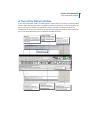
At the center of the Patran window is a blank graphics viewport where you construct your finite element
analysis model. The menu bar, toolbar, and application buttons shown below are your control panel. The
history area keeps you informed on what Patran is doing, and reports on what has occurred. The
command line is used to enter customized commands and the application forms are used to build each
part of your model. Differences between Windows and UNIX are noted.
34 MSC.Patran User’s Guide
How to Get Things Done
How to Get Things Done
This section contains basic information on using the different components in the Patran to complete tasks.
• Working with viewports
• Menubar
• Application buttons and forms
• System and Toolbar icons
• Command and history areas
• Picking and selecting
This information is intended to get you started using Patran. More detailed information can be found in
the Patran Reference Manual.
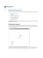
Working with Viewports
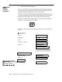
A viewport is a graphics window in which the entire model (or a selected portion of a model) appears. A
blank viewport, similar to the one shown below, appears at the center of the Patran window when you
create a new Patran database.
The top of the viewport lists the name of your database (in this case test.db), the name of the viewport
(default_viewport), the name of the current group (default_group), and the mode of operation for
Chapter 2: Fundamentals 35
How to Get Things Done
displaying the model (Entity). The Global Axes show the orientation of your model. A plus sign (+)
marker indicates the global origin.
To move and resize viewports within the Patran window:
1. Move the cursor over the Viewport title bar.
2. Click and drag the viewport to a new location.
3. Window machines allow for double clicking to fit the graphics window.
or
1. Move the cursor to any of the outside boarders or corners of the viewport.
2. When a two-headed arrow appears, click and drag the viewport to the desired size.
With Patran, there is no limit to the number of viewports you can create. Multiple viewports enable you
to see different views of the model, different parts of the model, and different analysis results.
To create multiple viewports:
1. Select Viewport/Create from the top menu bar.
The Viewport Create application form appears in the Patran window.
2. Enter a name for the new viewport in the New Viewport Name textbox, and click Apply.
Your original viewport is the default viewport, and each subsequent viewport that you create
appears in the Existing Viewports listbox.
The Menu Bar
The Menu Bar is located directly under the Patran title bar. Each menu keyword has a drop-down menu
with additional commands. The menu keywords are shown below.
File
When you invoke Patran, only the File menu is enabled; the other menus become enabled once you open
a database. The File menu provides access to the various files used by Patran, including database file
management, file importing and exporting, session file handling, hardcopy file creation, the status
database, and session exiting.
Group
The Group menu contains various options for you to organize into groups the geometric entities (points,
curves, surfaces, solids) and finite element entities (nodes, elements, multipoint constraints) of a Patran
model. You can then perform numerous modeling and postprocessing tasks on these groups.
36 MSC.Patran User’s Guide
How to Get Things Done
For example, you could group finite elements composed of different materials. Or, for viewing results,
you could create separate groups for displaying temperature and stress distribution on the same model
simultaneously.
Viewport
Viewports are movable, sizable graphics windows used to display all or part of a model. Each viewport
provides one independent view of a stationary model, and maintains a set of parameters to determine how
you want to view it.
Use the Viewport menu to create, edit, remove, and arrange your different viewports.
To move, resize, or create new viewports, see Working with Viewports.
Viewing
The Viewing menu contains various options to control the size and orientation of a model within a
viewport. You can manipulate a model’s rotational orientation, size, position, type of projection, scale
factors, and clipping planes. You can also control your viewport’s viewing plane, observer position,
window center, and focal point.
Changing your view in no way alters the model. With the Viewing menu options, you can pan, zoom in
and out of, rotate, and resize your model.
Viewing Size and Positions on the Toolbar
For quick changes in viewing orientation, select from the set of viewing icons on the toolbar. For
additional information on the toolbar, see Viewing Functions.
Also note that as you construct your model, Patran automatically resizes the viewport each time you add
an entity outside the current field of view. The viewport is adjusted to encompass all entities in your
current group.
More About Viewing Rotation
There are two ways to view the rotation of your model: around the model’s global axes or around your
screen’s axes. You can view each of these in absolute or relative terms, as shown in the table below:
Model Absolute
Rotation is about the global axes, starting from the axes’ zero rotation point.
Model Relative
Rotation is about the global axes, starting from the axes’ current location.
Screen Absolute
Rotation is about the screen axes, starting from the axes’ zero rotation point.
Screen Relative
Rotation is about the screen axes, starting from the axes’ current location.
Chapter 2: Fundamentals 37
How to Get Things Done
Display
Databases can get large and full of geometric and finite element entities. The Display menu helps you
organize and enhance the appearance of these entities. With the Display menu, you can determine which
entities you want displayed and how you want them displayed. And you can control numerous
visualization features, such as render style, entity plotting and erasing, highlighting, and label display.
The Display features do not affect the basic operations of Patran. They merely enhance the usability and
appearance of your models.
Preferences
With the Preferences menu, you can choose what parameters you want to govern the construction and
appearance of your model.
The Preferences menu defines global parameters that you can override in specific applications. For
example, during an equivalence operation, you can override the global model tolerance (the default
equivalencing tolerance). Patran, however, will not use the new tolerance value in subsequent operations
outside the given application.
The only way to change a preference permanently is to set it within a Preferences form.
Tools
The Tools menu executes the optional applications licensed at your site without exiting Patran. It also
provides a path to some of Patran’s newer, add-on features that you purchased at an additional cost. If an
application module is not licensed, the option for it on the Tools menu will be dimmed, indicating that it
is unselectable.
Using Lists
You can create numerous types of lists using the List option, including the following:
• You can, for example, build a list of entities having all nodes that equal zero.
• You can also combine lists to create other lists; for example all nodes equal to a certain value,
and all elements associated with that value.
• You can use List to perform Boolean operations.
Help
Use the Help menu to retrieve detailed online documentation for all of Patran’s features and tools.
Through the Help menu you can also access tips on keyboard shortcuts, mouse functions, and screen
picking.
38 MSC.Patran User’s Guide
How to Get Things Done
Application Buttons and Application Forms
There are a number of application buttons in the Patran window that relate to specific tasks in Patran. For
a standard FEA analysis, the radio buttons are arranged so that you can progress from left to right in the
course of your MSC.Patarn session. However, you can access most buttons at any time, once you have
created a database.
Brief descriptions follow for all the Patran application buttons.
Application
Function
Geometry
Creates and edits geometric models.
FEM (Elements)
Selects finite element shapes and creates a finite element mesh.
LoadsBCs (LBCs)
Assigns loads and boundary conditions.
Materials
Defines the material properties of the model.
Properties
Assigns element properties to model entities.
Load Cases
Defines load cases for your model.
Fields
Defines variation in properties and materials.
Analysis
Sets analysis parameters, submits the job, and reads result files.
Results
Defines how the results from the analysis display and plot.
XY Plot
Defines XY plots of results.
Chapter 2: Fundamentals 39
How to Get Things Done
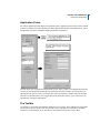
Application Forms
Selecting an application button displays an application form. Application forms are the primary method
to define your model and control the analysis. Many application forms have subordinate forms, such as
the Materials form and its subordinate Input Options form shown below.
You can choose only one application radio button at a time. Once you pick a second application from the
window, the second application form appears and the first form closes. While you can only have one
application form open at a time, you can have other forms open from the menubar. The tabs located at
the bottom of the forms allow you to toggle between the forms that you have open. You can close an
application by clicking its radio button.
The Toolbar
The toolbar is a set of often-used functions displayed as a row of icons. These functions are grouped into
several sets and used for model view control, render styles, predefined view orientations, and other
functions. It is customizable, so you can add your own functions and icons or remove them.
40 MSC.Patran User’s Guide
How to Get Things Done
You can rearrange the icons on the toolbar. Simply click and drag a set of icons to another area on the
toolbar or to another location in the Patran window.
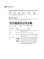
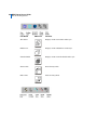
System Functions
The nine icons shown below are the system icons. At start up only two icons are active: the File New and
File Open. Once a database is opened, the remaining icons become active.
Icon Name
UNIX Icon
Function
File New
Use File/New
Brings up the New Database form.
File Open
Use File/Open
Brings up the Open Database form where you can select an
existing database to open.
File Save
Use File/Save
Updates any changes made to your database.
Print
Use File/Print
Prints the contents of a viewport or the XY window. You can
print a single viewport or window, or you may print multiple
viewports or windows.
Copy to Clipboard
Not Available
Copies the contents of the current viewport to the clipboard.
Undo
-Apply- or -OK- buttons perform actions that add, delete, or
modify entities in the database. To Undo the last operation
invoked by -Apply- or -OK-, press the icon that depicts a
reversal arrow. The graphics will refresh, all entities that
were deleted as a result of the last apply are redisplayed, any
entity that was added is erased, and any entity that was
modified is returned to its previous state.
Chapter 2: Fundamentals 41
How to Get Things Done
Icon Name
UNIX Icon
Function
Abort
There may be times during a session when you would like to
abort a time consuming operation. This can be accomplished
by depressing the icon depicting a raised hand. If the
heartbeat is spinning when depressing the icon, Patran
responds by presenting a form asking, “Do you want to
abandon the operation in progress?” This question requires a
yes or no response.
Reset Graphics
Removes all fringe and marker plots, all automatic titles,
highlighting, and deformed shape plots. Repaints the
viewport in wireframe mode. This button works on all posted
viewports in entity mode, but only on the groups posted in the
current viewport in group mode.
Refresh Graphics
Refreshes all of the graphics viewports.
Default Window
Layering
UNIX only. Brings the Main form to the front of the display
screen and layers other menus and viewports. This is
especially useful when the Main form has obscured the
viewport or other menus.
MSC Information
UNIX only. On Windows use Help/About Patran. This
includes the Patran release number, your customer name and
ID number, the X server and X Client information,
trademarks, copyright information, and access to the license
status program.
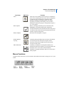
Mouse Functions
Using the toolbar icons below, you can customize the middle mouse button to change to view of your
model.
42 MSC.Patran User’s Guide
How to Get Things Done
Icon Name
UNIX Icon
Function
Mouse Rotate XY
Sets the middle mouse button to control model rotation
about the X and Y axes.
Mouse Rotate Z
Sets middle mouse button to control model rotation
about the Z axis.
Mouse Translate XY
Sets middle mouse button to control model translation
in the X and Y directions.
Mouse Zoom
Sets middle mouse button to control zoom in and out of
the model.
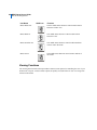
Viewing Functions
The Viewing menu located on the top menubar contains several options for controlling the view of your
model in the viewport. A subset of these options are quickly accessible from two sets of viewing icons
located on the toolbar.
Chapter 2: Fundamentals 43
How to Get Things Done
Icon Name
UNIX Icon
Function
View Corners
Zooms in on a cursor-defined rectangular area in viewport.
Fit View
Resizes the current view so that all entities display in the
current viewport.
View Center
Pans the model by moving the current viewport center to a
cursor-picked location.
Rotation Center
Not Available
Allows selection of the model’s rotation center by choosing
a point, node, or screen position.
Model Center
Not Available
Sets the rotation center to the centroid of the displayed
entities.
Zoom Out
Incrementally zooms out from the model by a factor of two.
Zoom In
Incrementally zooms in on the model by a factor of two.
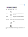
The next set of viewing icons define the orientation of the model in the viewport. By clicking one of the
icons below, you can quickly view your model from different angles. The default orientation is a front
view.
44 MSC.Patran User’s Guide
How to Get Things Done
Icon Name
UNIX Icon
Function
Front
X = 0, Y = 0, Z = 0
Rear
X = -180, Y = 0, Z = -180
Top
X = 90, Y = 0, Z = 0
Bottom
X = -90, Y = 0, Z = 0
Left Side
X = 0, Y = 90, Z = 0
Right Side
X = 0, Y = -90, Z = 0
Iso1
X = 23, Y = -34, Z = 0
Iso2
X = 23, Y = 56, Z = 0
Chapter 2: Fundamentals 45
How to Get Things Done
Icon Name
UNIX Icon
Function
Iso3
X = -67, Y = 0, Z = -34
Iso4
X = -157, Y = 34, Z= 180
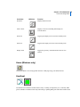
Display Functions
The two sets of Display icons located on the toolbar provide quick changes to the way in which you
display your model in the viewport.
46 MSC.Patran User’s Guide
How to Get Things Done
Icon Name
UNIX Icon
Function
Wire Frame
Displays model in wireframe render style.
Hidden Line
Displays model in hidden line render style.
Smooth Shaded
Displays model in smooth shaded render style.
Show Labels
Plots all entity labels.
Hide Labels
Erases all entity labels.
Chapter 2: Fundamentals 47
How to Get Things Done
Icon Name
UNIX Icon
Function
Plot/Erase
Displays Plot/Erase form.
Label Control
Displays a form for controlling label display for
selected entities.
Point Size
Toggles point display size between one and nine pixels.
Node Size
Toggles node display size between one and nine pixels.
Display Lines
Toggles the geometry visualization lines between zero
and two.
Home (Windows only)
Click on the Home icon to bring up MSC Software’s Web page using your default browser.
Heartbeat
The Heartbeat icon indicates whether Patran is busy or waiting for input from you. A stationary MSC
globe on Windows machines means ready and waiting. A spinning MSC globe with a blue boarder means
48 MSC.Patran User’s Guide
How to Get Things Done
busy, but can be interrupted. A spinning MSC globe with a red boarder means busy, cannot be
interrupted. On UNIX it is a solid square with the same color meanings.
Command Line and History List Area
The Command Line and History List Area appear at the bottom of the Patran window. You can manually
enter commands in the command line. The history list area is used to view the commands that Patran
generates when a menu form is executed, and to view errors or informative messages. You can resize the
History window in order to see more lines in the History List Area.
Picking and Selecting
Many times when you are working with application forms, a menu of icons appears to the left of your
form. From this Select menu you can choose objects directly off the screen rather than typing in data on
the application form. By selecting one of the Picking Filters from the Select menu, you control what type
of objects you pick off the screen and how you select the object.
Picking and selecting off the screen can be a complex task. This section covers basic information about
several aspects of the Select menu.
• Types of Select menus.
• Different levels within Select menus.
• Menu appearance.
• How to pick entities from the screen.
• Picking operations.
Select Menus
There are over 25 different Select menus in Patran. The Select menu that appears on your screen depends
on the application in which you are working. For example, if you are creating a new point in your
geometry model, the Point Select menu appears. Alternatively, if you want to select a finite element from
a mesh that you have already generated, you will see the Element Select menu on your screen.
Each Select menu displays a series of graphic icons. As you move the cursor over each icon, the filter
name appears next to the icon. The first four icons are common to all Select menus and control overall
picking and navigating functions. The remaining icons are specific to each Select menu and act as
picking filters
An example of the Point Select menu is shown below.
Chapter 2: Fundamentals 49
How to Get Things Done
Icon
Function
Toggle Visible Entities Only Selection
Selects either visible objects only, or visible and
hidden objects.
Polygon Pick
Selects all objects that lie within a polygon area.
Go to Root Menu
Reverts back to the original Select menu.
Go to Previous Menu
Reverts back to the previous Select menu.
Any Point
Selects a point associated with any geometric or finite
element object.
Point
Selects a point.
Node
Selects a node.
Curve Intersect
Selects the point at which two curves intersect.
Point on Curve
Selects a point on a curve closest to a point off the
curve.
Any Vertex
Selects the vertex of a curve, surface, or solid.
Pierce
Selects the point where a curve and a surface
intersect.
Point on Surface
Selects a location on a surface.
Screen Position
Selects a X-Y screen position.
Multilevel Select Menus
Some of the Picking Filter icons you select will display a second and perhaps a third level Select menu.
Each lower level menu in the hierarchy automatically replaces the previous Select menu. Only one
Picking Filter menu is active at a time. As you continue to make filtering selections you further define
how you will pick the object off the screen.
To navigate through different levels of menus in the hierarchy, use the two icons near the top of each
Select menu:
50 MSC.Patran User’s Guide
How to Get Things Done
Click on the Go to Previous Menu icon to return to the previous Select menu
or
Click on the Go to Root Menu icon to return to the original Select menu
Appearance of the Select Menu
By default, the Select menu appears as a set of icons arranged vertically and docked in the application
form area. Like Patran’s toolbar, you can undock and reposition the Select menu as a free floating menu
at any time. You can also dock the Select menu on the left side of the window, in the toolbar area, or at
the bottom of the window. Any changes that you make to the appearance or location of the Select menu
remains in effect each time you open a database.
To change the appearance of the Select Menu:
1. Move the cursor over the title bar area of the Select menu.
2. Click and drag the menu to a new location.
The Select menu can appear as a free floating menu anywhere in the viewport.
or (on Windows)
1. To maintain a vertical set of icons, click and drag the Select menu to the left side of the Patran
window and release.
2. To switch to a horizontal set of icons, click and drag the Select menu to the toolbar area or to the
History/Command Line area.
Picking an Entity off the Screen
There are two basic methods of picking entities off the screen: enclosing an entity by drawing a boundary
around it, or pointing directly at the object, and selecting it.
Enclosing Entities
You can use the enclose function to select any number of objects off the screen at one time. This is
especially useful when you want to select a large number of objects that you would otherwise have to
select one by one.
On the Select menu there are two types of boundaries that you can use to enclose objects: a rectangular
boundary and a polygon boundary. The rectangular boundary is the default. The polygon boundary offers
more flexibility in defining the shape of the boundary.
To use the Polygon boundary:
Chapter 2: Fundamentals 51
How to Get Things Done
1. Click on the Polygon icon located on the Select menu (on UNIX this icon is in the main
toolbar).
2. First move the cursor into the application form databox and click.
3. Next move the cursor into the viewport. Click once to define the first vertice of the polygon.
From there you can move and click the cursor as many times as is necessary to define your
polygon.
To use the rectangular boundary:
1. Click in the application form databox and then move the cursor into the viewport.
2. Click and drag the cursor arrow to define an enclosing rectangle.
What happens when an object lies partially within and partially outside the boundary you drew?
This depends on your picking preferences. Using the Preferences/Picking menu from the menu bar,
you can specify that the object needs to be entirely enclosed, partially enclosed, or only the centroid
need be enclosed. This preference then instructs Patran whether to include or exclude an object lying on
the boundary.
Selecting Individual Entities
On each Select menu there are typically several icons that control how you pick individual objects off the
screen. These features are most useful when you are selecting one or two objects, or when the desired
objects are located such that you can’t enclose them using a boundary.
The filtering icons are specific to the application. The default picking icon is the Any icon.
Using
this function you can select any object off the screen that corresponds to the current application. This is
essentially the unfiltered picking function.
To select an object:
1. Click in the application form databox and then move the cursor into the viewport.
2. Point the cursor arrow at the desired object and click.
or, to be more selective in your picking:
1. Select one of the picking filter icons on the Select menu.
2. Click in the application form databox and then move the cursor into the viewport. Point the cursor
at the desired object and click.
Changing the Picking Operation
Using the Select menu you can add an entity to an application form, replace an existing entity on the form,
or remove an already selected entity form a form. When the Select menu first appears, it is in Replace
52 MSC.Patran User’s Guide
How to Get Things Done
mode. Any entity that you select from the screen replaces an existing entity if one is designated in the
databox.
To change this mode to add or remove entities:
1. From the Patran menu bar, select Preferences/Picking.
The Picking Preferences menu appears in the Application form area.
2. Click on the Show Picking Icons checkbox.
This instructs Patran to add a set of Picking Operation icons to your Select menu. You will see a
message box informing you that you need to restart Patran in order for this change to take place.
3. Quit and restart Patran.
4. Resume the Application that brings up your Select menu.
Chapter 2: Fundamentals 53
How to Get Things Done
You should now see the three additional picking operation icons. These icons remain on each
Select menu until you change the Picking Preferences form again.
5. Click on one of the other Picking Operation icons to change the Picking mode.
This operation changes a setting in a file called settings.pcl, generally located in the installation directory.
If this operaiton does not work it is usually because there are no permissions set to change this file. You
may need to either change the permissions or copy the file to the directory from which you are running
and do the operation again.
Picking objects from the viewport can be a difficult task. The features discussed in this section are the
basic features of picking and selecting. For more information about individual picking icons, select
menus, and picking off the screen, please refer to the Patran Reference Manual, Volume 1, Part I
Introduction to Patran, Chapter 3: Interactive Screen Picking.
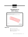
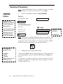
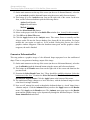
Exercise 1
Introduction to
MSC.Patran
Objectives:
■ Create geometry for a Beam.
■ Add Loads and Boundary Conditions.
■ Review analysis results.
MSC.Patran 301 Exercise Workbook - Release 9.0
1-1
Notes about this exercise:
- This document contains specific instructions for a slightly different version of Patran
than we have available on the EWS machines. Discrepancies between this document
and our Patran interface will be indicated with comments in dashed boxes.
- This document gives instructions to perform analysis with MSC sftware, however we
will use Abaqus for our analysis. Sections 16-18, which pertain to analysis and
results, will be replaced with other Abaqus instructions.
1-2
MSC.Patran 301 Exercise Workbook - Release 9.0
Exercise 1
Geometry Model of Space Satellite
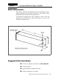
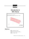
Model Description:
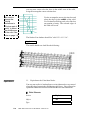
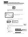
This exercise will take you through the steps of modeling an openended aluminum box beam that is welded to a rigid surface. It has
dimensions that are shown in the diagram below.
A downward 100-pound force will be applied, as shown. You will
determine how much the box beam will deflect, as well as the
maximum von Mises stress.
Suggested Exercise Steps:
■ Create a new database and name it as box_beam.db.
■ Create geometry.
■ Apply boundary conditions and loads.
■ Analyze model and view results.
MSC.Patran 301 Exercise Workbook - Release 9.0
1-3
Exercise Procedure:
Note: In most MSC.Patran forms, the default setting for the Auto
Execute button is on; thus, you do not need to press Apply.
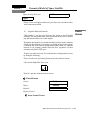
1.
Open a New
Database
Create a new database and name it box_beam.db.
File/New...
New Database Name
Navigate to the
directory you want in
the New Database
Dialogue Box.
You can save to your
home directory sub
directories in your
home directory on
the EWS machines.
box_beam
OK
New Model Preferences
Tolerance:
Default
Analysis Code:
MSC/PATRAN_FEA
Analysis Type:
Structural
OK
Analysis Code:
ABAQUS
No Mapping
Note: If the analysis code MSC/PATRAN_FEA is not available to you,
choose another structural analysis code for which you have licenses.
If the part of the screen which was covered by the New Model
Preferences form is not redrawn, press the refresh button:
To change the
viewpoint color:
2.
- Viewport
- Modify
- Change
"Background color" in
"Attributes" box
1-4
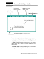
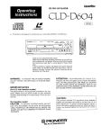
A Short Word on Viewports and Groups
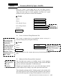
After pressing OK on the New Model Preferences form, you should
see a large graphics window, called the MSC.Patran Viewport (see
below).
A viewport is a window in which you view your model. You can
display more than one viewport, but to keep it simple we will be
working with only one.
MSC.Patran 301 Exercise Workbook - Release 9.0
Geometry Model of Space Satellite
Exercise 1
Viewport Name
("default_viewport")
Database Name
("box_beam.db")
Current Group Name
("default_group")
Operational Mode
("Entity or Group Mode")
The Current Viewport has a bright red border
The top of the viewport lists the name of database you are working on,
the name of the viewport, the name of the current group you are
working with, and the mode of operation for displaying the model
(Entity or Group mode).
A Group is a defined collection of geometry and/or finite element
entities. Entities, such as a surface or an element, can belong to more
than one group.
The Current Group is a specified group to which all newly created
entities will belong. You can only specify one group at a time to be the
current group for each viewport.
MSC.Patran 301 Exercise Workbook - Release 9.0
1-5
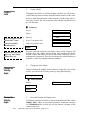
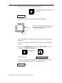
3.
Create a
Solid
Create a Solid
Though the box beam we will be creating is hollow, we will create a
solid of the box beam and later, mesh the outside surfaces of the solid.
Keep in mind the dimensions of the beam are 5 inches long with a 1
inch cross section. We will create the solid with the long direction in
the +X direction.
Geometry
Try rotating the model
about the XY axis
using the middle
mouse button
Experiment with view
type, e.g. wire frame,
hidden line, etc.
Action:
Create
Object:
Solid
Method:
XYZ
Vector Coordinates List
<5, 1, 1>
Origin Coordinates List
[0, 0, 0]
Apply
For fun, rotate the model by placing the cursor in the viewport and
holding down the middle mouse button and dragging the mouse
around. Notice that when you release the button a View/Fit View is
automatically performed. You can switch from the rotate function to
translate or zoom by entering Preferences/Mouse...
4.
Change the
Viewing
Angle
Change the View Angle.
Instead of using the middle mouse button to change the view of the
model, you can use the Viewing menu, by doing the following:
Viewing/Angles...
Model Absolute
Angles
20 -10 0
Apply
Cancel
5.
Change the
Viewing
Angle
Reset the Number of Display Lines
All surfaces and faces of solids are shown with additional lines, called
Display Lines. These are not actual geometric boundaries, but they
are visualization lines to help you see the interior curvature of the
surfaces and faces.
1-6
MSC.Patran 301 Exercise Workbook - Release 9.0
Geometry Model of Space Satellite
Exercise 1
Sometimes you may need to simplify the display of your model by
lowering the number of Display Lines, and this is done as follows:
Display/Geometry
Number of Display Lines
1
Apply
Cancel
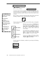
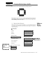
6.
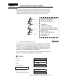
Create the Displacement Boundary Conditions.
MSC.Patran has this wonderful ability to associate the loads and
boundary conditions (Loads/BCs) either with the geometry or with the
finite element model.
The Loads/BCs associated with the geometry will be applied
automatically to the nodes and elements when they are created. If you
decide later to remesh the model, the Loads/BCs will be automatically
revised. This means you can remesh your model as many times as you
wish and you won’t have to worry about reassigning the Loads/BCs to
the mesh - MSC.Patran will take care of it for you!
For our box beam model, we want to "fix" the welded end of the beam
by defining no movement in all six degrees of freedom, which is
represented by six zeroes. (A null or blank value, instead of a zero,
means the specific degree of freedom is free to move.)
To apply the fixed boundary condition:
Loads/BCs
Action:
Create
Object:
Displacement
Type:
Nodal
New Set Name
fixed
Input Data...
Translations <T1,T2,T3>
<000>
Rotations <R1 R2 R3>
<000>
Analysis Coordinate Frame
Coord 0
OK
MSC.Patran 301 Exercise Workbook - Release 9.0
1-7
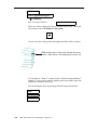
Create
Boundary
Conditions
Very
important!
Select Application Region...
Geometry
Select Geometry Entities
You may need to
change your picking
option here:
- Preferences
- Picking
- Select "Enclose
entire entry" in the
"Rectangle/Polygon
Picking" box
Alternatively you
can shift+click to
select multiple
edges
At the left of the menu you should see a select menu. By default the
Geometric Entity icon is highlighted, which means MSC.Patran will
look for all geometry entities when you cursor select entities in the
viewport.
But we want to cursor select only the edges of the solid for our fixed
boundary conditions. Thus, click on the Curve or Edge icon:
Cursor select the left end edges of our solid by using a rectangular
cursor selection:
With the cursor at point “A”, hold down the
left mouse button and drag the cursor to
point “B”, so that you have drawn a
rectangular box around the left end edges of
the solid, as shown. Then, release the
mouse button.
Note: MSC.Patran highlights the selected
edges in red, and the “Select Geometry
Entities” databox will list the solid edge
IDs. (i.e., Solid 1.1.1, 1.1.2, 1.1.3, etc.).
If you are not happy with what you have
selected, you can deselect the edges by
using the right mouse button.
Finish creating the boundary condition by pressing the following
menu buttons:
Add
OK
Apply
1-8
MSC.Patran 301 Exercise Workbook - Release 9.0
Geometry Model of Space Satellite
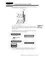
Exercise 1
You should see light blue “cones” being drawn on the end of the solid
at the Display Lines’ point locations (shown below). These represent
the three fixed translational and the three fixed rotational boundary
conditions. Remember, these have been applied to the geometry!
If you ever need to come back
and view the boundary
conditions again go to:
- Load/BCs
- Action: Plot Markers
- Select loads or BCs you want
to view in the "Assigned Loads/
BCs Sets" box
- Select "default_group" in
"Group Filter" box
- Click apply
7.
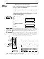
Apply Load
Apply the 100-pound Force Load.
Now we want to finsh our Loads/BCs by applying our 100-pound
downward force on the right corner of the solid. The force will be
defined by a vector in the global rectangular coordinate frame, where
we will have zero pounds in the +X direction, 100 pounds in the -Y
direction and zero pounds in the +Z direction.
Again, we don’t need to create the finite element mesh before applying
our force. We can associated the force with the solid.
Loads/BCs
Action:
Create
Object:
Force
Type:
Nodal
New Set Name
100_pounds_down
Input Data...
Force <F1 F2 F3>
< 0 -100 0 >
Analysis Coordinate Frame
Coord 0
MSC.Patran 301 Exercise Workbook - Release 9.0
1-9
OK
Select Application Region...
Geometry
Select Geometry Entities
Since we want to apply our force to a point on the solid, switch the
select menu icon to the Point or Vertex icon:
Cursor select the corner point of the right end of the solid, as shown:
Click on this corner of the solid with the left mouse
button. MSC.Patran will highlight the point in red.
You should see “Point 7” entered in the “Select Geometry Entities”
databox. If you cursor selected another point by mistake, press the
right mouse button to deselect it.
Finish creating the force by pressing the following menu buttons:
Add
OK
Apply
1-10
MSC.Patran 301 Exercise Workbook - Release 9.0
Geometry Model of Space Satellite
Exercise 1
Now you should see a yellow arrow drawn on the selected corner point
of the solid which is our 100-pound force:
100.0
8.
Create a New Group
Before we go on and mesh our box beam model, we want to keep our
soon-to-be finite element mesh in a group that is separate from our
geometry model.
Create a
New Group
To do this, we will created a new, empty group called “fem_model”
and make “fem_model” our current group.
Group/Create...
New Group Name
fem_model
Make Current
Group Contents:
Add Entity Selection
Entity Selection
Apply
Cancel
Note: “fem_model” has replaced “default_group” at the top of our
viewport, which means “fem_model” is our new current group.
MSC.Patran 301 Exercise Workbook - Release 9.0
1-11
9.
Define
Mesh Seeds
Define Mesh Seeds on one end of the Solid.
Before we mesh the outer surfaces of our solids, we want to take
advantage of a feature called Mesh Seeds.
Mesh Seeds allow you to define exactly how many elements (and even
what node spacing) you want on selected curves or edges of a surface
or a solid.
For our box beam model, we want to define mesh seeds of five
elements in the Y and Z directions and 15 elements in the X direction.
To do this, we do the following:.
Just called
"Elements"
Finite Elements
Action:
Create
Object:
Mesh Seed
Type:
Uniform
Number of Elements
Number=
5
Curve List
In our version
you can
select either
Because mesh seeds can only be associated with curves or with edges
of surfaces or solids, the select menu only has one icon. This means
MSC.Patran will only look for any curves or edges that you select.
Since we want to select the edges of the solid that are in the Y and Z
directions, use the rectangular cursor select box and cursor select the
edges on the left end or the right end of the solid (the illustration
below shows the solid’s right end edges being selected):
Use the rectangular cursor selection box and
select the edges on the left or right end of the
solid
If auto execute is selected, do not click
apply.
Apply
1-12
If you accidentally click apply, select NO
when the warning box asks if you want to
duplicate seeds.
MSC.Patran 301 Exercise Workbook - Release 9.0
Geometry Model of Space Satellite
Exercise 1
Now we want to create our second mesh seed for 15 elements in the X
direction:
Number of Elements
Number=
15
Curve List
Shift + click to
select all four
edges
Select one of the 4 edges in the middle area of the solid. The selected
edge of the solid will be red.
Apply
10.
Mesh the Outside Faces of the Solid with Quad4s
Meshing
Now we’re ready to create our finite element mesh. Though we have a
solid, we want to create a surface mesh made of 4-noded quadrilateral
elements (Quad4s). MSC.Patran allows you to create a surface mesh
on the faces of our solid.
To do this, do the following:
Finite Elements
The order of these
objects is different
on our version of
Patran.
Action:
Create
Object:
Mesh
Type:
Surface
Global Edge Length
Select "Quad" for
"Element Shape"
and "Isomesher"
for "Mesher"
Element Topology:
0.1
Quad4
IsoMesh
Surface List
Notice the select menu will only allow you to select surfaces or solid
faces, because the Type option on the Finite Elements form is set to
"Surface". Again, either individually select the outside solid faces
(not including the two ends) using shift/click, or:
MSC.Patran 301 Exercise Workbook - Release 9.0
1-13
you may now cursor select the faces in the middle area of the solid,
using the rectangular cursor selection box:
We need to
change the
picking
preference to
"Enclose part of
entity" to select
the middle area
of the solid. See
note on page 1-8
Use the rectangular cursor selection box and
select the edges in the middle of the solid.
Use Preferences/Picking and select Enclose
any portion of entity. The selected edges of
the solid will be red.
The Surface List databox should list "solid 1.3 1.4 1.5 1.6".
Apply
The model should now look like the following:
Equivalence
11.
Equivalence the Coincident Nodes.
You may not realize it, but duplicate or coincident nodes were created
along the edges between the neighboring solid faces. You will need to
equivalence the nodes to remove each on of the two coincident nodes.
Finite Elements
1-14
Action:
Equivalence
Object:
All
Type:
Tolerance Cube
MSC.Patran 301 Exercise Workbook - Release 9.0
Geometry Model of Space Satellite
Exercise 1
Equivalencing Tolerance
0.005
Apply
Purple circles will appear which tell you where the coincident nodes
were found and removed.
12.
Align the Element Normals.
"Why bother?", you may ask? You may not realize it, but 2-D shell
elements, like the Quad4s used in this box beam model, have a defined
top and bottom surface for results output.
Element
Normals
By default, the Quads4s we created have their positive surface normals
(which are the elements’ top surfaces) pointing in the positive global
coordinate directions. But for postprocessing the results, we want the
normals to be pointing outward from the box, regardless of their
orientation in global XYZ space.
To show you what we mean, let’s first plot the existing normal vectors
by doing the following.
First, reset the view by looking down on the end of the box beam
Click on the Right Side View icon:
Y
Z X
Now let’s plot the element normal vectors:
Finite Elements
Action:
Verify
Object:
Element
Method:
Normals
Display Control
Draw Normal Vectors
MSC.Patran 301 Exercise Workbook - Release 9.0
1-15
Make sure the Test Control icon looks like this:
It should state "Display Only" on
the side
Apply
You should see red arrows being plotted that look like this:
We want to reverse the element normal
directions on these two sides of the box
so they point outward.
Notice the normals are aligned with the +Y and +Z global coordinate
directions.
Now, let’s reverse the normal directions of the two sides indicated
above.
First, press the Display Only icon, under Test Control, so that it
changes to the Reverse Elements icon:
Changes to:
Guiding Element
Use the left mouse button and pick one element from the top surface
which is pointing in the "correct" or outward direction.
Apply
1-16
MSC.Patran 301 Exercise Workbook - Release 9.0
Geometry Model of Space Satellite
Exercise 1
You should see the element normals all pointing outward:
The normal vectors’ red arrows can be erased by either pressing the
Reset Graphics button, or by exiting the Finite Elements Application
and continuing on to the next step.
13.
Define the Material Properties.
Since the box beam is made of aluminum, we can assume the material
is isotropic and it will behave in the linear elastic region. To create the
material property:
Define
Material
Properties
Materials
Action:
Create
Object:
Isotropic
Method:
Manual Input
Material Name
aluminum
Input Properties...
Constitutive Model:
Click "OK" to
dismiss the
"Input
Properties" box
Linear Elastic
Elastic Modulus=
10.0e6
Poisson Ratio=
0.3
Density=
0.000259
Just "Elastic"
Thermal Expand. Coeff.=
Apply
Cancel
MSC.Patran 301 Exercise Workbook - Release 9.0
1-17
14.
Define
Element
Properties
Define the Element Properties
Now we will define the element properties for our Quad4 elements.
The elements have a thickness of 0.05 inches and should reference the
aluminum material property that we have just created.
We will associate the element properties with the geometry model, and
not the finite elements. This will allow MSC.Patran to reassociate the
properties to the elements if we later decide to remesh the model.
First let’s reset the view to make it easier to cursor select our elements.
Press Iso 1 View icon from the toolbar:
Y
Z
X
Now let’s create our element property and reference it to our geometry
model:
Properties
Action:
Create
Dimension:
2D
Type:
Shell
Property Set Name
box_beam_shell
Option(s):
Homogenous
Standard Formulation
*
* May not be an option depending on your analysis preference.
Input Properties...
Material Name
m:aluminum
Thickness
0.05
OK
Click "Select
Application region…"
1-18
Select Members
MSC.Patran 301 Exercise Workbook - Release 9.0
Geometry Model of Space Satellite
Exercise 1
Since we want to associate our element properties with the outside
surfaces (faces) of our solid, make sure the Surface or Face icon is
highlighted in the select menu:
Now cursor select the entire model (remember our solid is still in the
group, "default_group", which is still posted (displayed) to the
viewport) Click on the Iso 1 View icon at the top to see the whole
model:
Select the entire model using the
rectangular selection box.
You should see "Solid 1.1 1.2 1.3 1.4 1.5 1.6’ appear in the databox
which are the solid face ID’s.
Add
Click "OK" to exit "Input
Properties" box
Apply
15.
Create a Load Case
Now we want to create a load case which groups selected loads and
boundary conditions into a single set which can be referenced for the
analysis.
Create a
Load Case
Load Cases
Action:
Create
Load Case Name
(load case description)
load_case_1
Make Current
Load Case Type:
Static
MSC.Patran 301 Exercise Workbook - Release 9.0
1-19
Description
- Click "Input Data…"
- Select "Disp_fixed"
and "Force_100pound_down" to add
to spreadsheet
load_case_1
Description is
optional
Now click on the Assign/Prioritize Loads/BCs button.
Select Loads/BCs to add to
spreadsheet
Disp_fixed
Force_100-pound_down
OK
Apply
16.
Analyze /
Job Status /
Results
Perform the Analysis / Check Status of Job / Read Results
Now we are ready to submit our finite element model for analysis.
Under Analysis, we will set up the job for the analysis and submit it
directly from MSC.Patran to MSC.Nastran.
We will skip steps
16-18 in this
document, follow
modified steps at end
of this document
instead
Analysis
Action:
Analyze
Object:
Entire Model
Method:
Full Run
Job Name
box_beam_loadcase_1
Translation Parameters...
Subcase Create...
If you have time, you may
want to look at the subordinate forms for these options.
The defaults for these
options are fine for our
model.
Subcase Select...
load_case_1
Solution Type...
Direct Text Input...
OK
Apply
After pressing Apply, the heartbeat on the main form will turn blue
and you should see a number of messages scroll by in the Command
Line. The heartbeat will then turn to green which means you can
continue executing operations in MSC.Patran while the analysis is
running.
To see if MSC.Nastran has completed with no errors, open another
window and search the contents of the file, box_beam_loadcase_1.f04
in the directory where you started up MSC.Patran for the string EXIT:
1-20
MSC.Patran 301 Exercise Workbook - Release 9.0
Geometry Model of Space Satellite
Exercise 1
For UNIX, enter:
% more box_beam_loadcase1.f04 | grep EXIT
For Windows NT, enter:
% type box_beam_loadcase1.f04 | find "EXIT"
If MSC.Nastran completed with no errors, you should see the
following line:
16:23:52 0:20 20.2 0.0 11.4 0.0 SESTATIC 145 EXIT BEGN
Once the analysis has successfully completed, it will produce a
box_beam_loadcase_1.op2 results file. This file must be read into the
MSC.Patran database before you can begin to postprocess the results.
Analysis
Action:
Read Output2
Object:
Result Entities
Method:
Translate
Available Jobs
box_beam_loadcase_1
Select Results File...
Available Files
box_beam_loadcase_1.res
OK
Apply
You should see messages appear in the Command Line, stating which
results are being read into the database.
Now we are ready to postprocess the results.
17.
Unpost (Erase) the Geometry Group.
MSC.Patran 301 Exercise Workbook - Release 9.0
Unpost
Geometry
Group
1-21
Since we are done using the geometry, let’s erase or "unpost" the
group, "default_group", which contains the geometry part of our
model:
Group/Post...
Select Groups to Post
fem_model
Apply
Cancel
Notice the Loads/BCs symbols go away because they are associated
with the geometry that is part of "default_group", which is now
unposted.
Create a
Deformation
Plot
18.
Create a Deformed Shape Plot
Let’s create a deformed shape plot based on the displacement results.
This is an excellent way to view the response of our structure. Note:
The numbering of the result cases may vary.
Results
Action:
Create
Object:
Deformation
Select Result Case(s)
Select Result
1.1-DISPLACEMENTS,
TRANSLATIONAL
Apply
Although there are other ways to reset the graphics display of our
model back to the default wireframe, the easiest way is to press Reset
Graphics icon at the top before creating another postprocessing
results plot.
Start here after completing analysis with
Abaqus and creating the deformation plot
Create a
Fringe Plot
19.
1-22
Create a Fringe Plot of the von Mises Stresses.
MSC.Patran 301 Exercise Workbook - Release 9.0
Geometry Model of Space Satellite
Exercise 1
Next, let’s create a color fringe plot of our von Mises stresses.
Invariant stresses, such as von Mises stresses, are a good choice for a
fringe plot since they are scalar quantities, and they are a good
predictor of the yield stress in metals like aluminum.
Results
Action:
Create
Object:
Fringe
Select Result Case(s)
Select Fringe Result
Stress...
Quantity:
von Mises
"Stress,
components"
Apply
20.
You can view/hide
the undeformed
configuration by
clicking the
"Display Attributes"
icon near the top
of the "Results"
pane, then select/
unselect "Show
Undeformed" and
click "Apply"
Let’s create a contour plot of our membrane stresses on top of a
deformed shape plot by doing the following:
Results
Action:
Create
Object:
Deformation
Apply
Select "Deformation,
Displacements" in the
"Select Deformation
Result" box
Now you should see the contour plot on top of the deformed shape
plot.
21.
Step 21 will not
be covered in
the lab
sessions
Create a Combined Fringe/Deformed Plot
Modify the Finite Element Mode (Optional)
Note the high stress regions are bending stresses in the opposing
corners at the box beam’s open end (opposite of the welded end). But
they are well below aluminum’s 30 ksi yield stress.
Being the good engineer that you are, you realize the design could be
greatly improved by welding a cap on the open end of the beam.
Try posting the geometry model ("default_group") and mesh the solid
face on the open end. You can then quickly equivalence and optimize
the model and assign the existing element properties to this new area.
MSC.Patran 301 Exercise Workbook - Release 9.0
1-23
Run the model through MSC.Nastran again and see if the stress levels
improve. Good luck!
Close the
Database
and Quit
MSC.Patran
22.
Close the Database and Exit MSC.Patran.
File/Quit
Changes to your model will be automatically saved when you close
your database or exit MSC.Patran.
Congratulations and give yourself a big pat on the back!
You have just had a glimpse of the future -- the way productive people
will be doing finite element analyses from now on.
And there’s much more! Try accessing a CAD model, creating varying
loads and element or material properties through the use of Fields,
interpolating results from one analysis onto another model as loads,
and using the Finite Element Sweep mesh creation.
Examples of these and other features of MSC.Patran can be found in
Part 10: Example Problems in the MSC.Patran User’s Manual.
1-24
MSC.Patran 301 Exercise Workbook - Release 9.0
Abaqus analysis steps
These steps replace Patran steps 16-18 in the Box_Beam exercise
PERFORM THE STEPS BELOW INSTEAD OF PATRAN STEPS 16-18 IN
THE BOX_BEAM EXERCISE
Create the Abaqus Input File for Box Beam Model
All aspects of the finite element model are now defined. Thus the Abaqus input file can be
generated.
1. On the main menu across the top of the screen (on the row of diamond buttons), select the
one for ♦Analysis (push the diamond button using the mouse and left mouse button).
2. This brings up a new Analysis menu form on the right side of the screen and dismisses
the Loads/BCs menu form. In the new form, use the left mouse button to pick the
following entries:
Action: Analyze
Object: Entire Model
Method: Analysis Deck
3. Click the Job Name box, then type box_beam (the job name is user definable. The
Abaqus input file will then be named box_beam.inp).
4. Click the Optional Controls button. This brings up the Optional Controls menu.
5. Change the Results File Type: to FIL and ODB. Click Apply.
6. Click the Step Creation button. This brings up the Step Create menu.
7. Select the Default Static Step in the Available Job Steps box.
8. Click the Output Requests button. This brings up the Output Requests menu which
lists various kinds of stress, strain, displacement, etc. output that can be requested.
9. Change the Form Type: from Basic to Advanced.
10. For BOTH Stress Component (S) and Strain Component (E), we want to change the
Element Position: from Integration Pts to Nodes. This will request that Abaqus output
values at the nodes of each element. Click Ok on the Output Requests menu to save
requests and dismiss the menu.
11. Click Apply (click Yes if asked whether to overwrite), then the Cancel button in the Step
Create menu. This saves values and dismisses the menu.
12. Click the Apply button on the remaining main Analysis menu. This causes Patran to
actually write the Abaqus input file. For larger models this can require as much as 10
seconds. During this process, the Patran graphics window disappears. When the
heartbeat (at the top right corner of the screen) turns green and the graphics window
reappears, the task is finished. The Abaqus input file is now named box_beam.inp (based
on the responses given above).
13. If you would like to take a look at how the input file was generated, open the input file
named box_beam.inp with a text editor. In the Terminal for example, type
Abaqus analysis steps
These steps replace Patran steps 16-18 in the Box_Beam exercise
gedit box_beam.inp
Other options are:
gvim box_beam.inp
nano box_beam.inp
Hint: If you are using nano, you can press Control+W and perform a search for the
keyword you are looking for. This comes in handy in large files. Emacs has the same
functionality too.
Run Abaqus to Perform Analysis
14. In an X-terminal window, change to your work directory then initiate execution of
Abaqus using the command:
abaqus –j box_beam
Abaqus now starts execution to perform the analysis.
*NOTE1: If this throws a “-bash” error, type: module load abaqus
This will load abaqus to your directory.
*NOTE2: A second option for running Abaqus is to simply type abaqus
Abaqus will run interactively and ask for the *.inp filename
identifier
:
box_beam
The program runs in the 'background'. This enables continued use of the X-terminal
window. Abaqus is a fast program for linear analysis and most jobs for our classes
complete quickly. It will take around 10-15 sec to finish it, although in X-terminal
window it would seem like it was executed in a second. To check the status type ps in the
X-term. If you see box_beam.com under the list of the ps commands that would mean, the
program is still running.
Several key files produced by Abaqus during execution (using box_beam as the identifier
if given above, otherwise they will have the same filename):
box_beam.dat contains the printed error messages, results and other comments
box_beam.log contains a very short summary (20 lines) of the starting and stopping
steps in the analysis. Simply display this file to determine when your analysis is
completed. Use the command: cat box_beam.log
box_beam.fil contains the results in binary form for PATRAN to read.
Import Results Into Patran Database
In this step, we will 'import' the nodal displacements, stress and strain into the Patran database
for this model and generate a graphical image of the deformed shape. Perform the following
sequence of actions:
Abaqus analysis steps
These steps replace Patran steps 16-18 in the Box_Beam exercise
15. On the main menu across the top of the screen (on the row of diamond buttons), select the
one for ♦Analysis (push the diamond button using the mouse and left mouse button).
16. This brings up a new Analysis menu form on the right side of the screen. In the new
form, use the left mouse button to pick the following entries:
Action: Read Results
Object: Result Entities
Method: Translate
17. Click the Select Result File button.
18. Select on the proper result file in Available Files window (box_beam.fil in this example).
19. Click OK on the Select File menu.
20. Click the Apply button on the Analysis menu. This causes Patran to actually read the
Abaqus results file into the Patran database (box_beam.db) for this problem. For larger
models this can require as much as 10-20 seconds. During this process, the Patran
graphics window disappears. When the heartbeat turns green and the graphics window
reappears, the task is finished.
Generate a Deformation Plot
This step produces a graphics image of the deformed shape superposed over the undeformed
shape. Then we can generate a hardcopy output of the image.
21. On the main menu across the top of the screen (on the row of diamond buttons), select the
one for ♦Results (push the diamond button using the mouse and left mouse button).
22. This brings up the Results menu form on the right side of the screen and dismisses the
previous menu.
23. Examine the Select Result Cases ‘box’. There should be available selections. Select the
bottom one in the ‘box’. Examine the Select Deformation Result 'box'. Select the option
Deformation Displacements. Click the Apply button at the bottom of this menu.
24. The undeformed image changes to a have blue lines, with the deformed image in white
color lines for triangle elements.
25. Now we will 'animate' the result as thought the deformed shape is a 'mode' shape from a
vibration analysis. Click the Animate button just above the Apply button on the Results
menu. Click Apply on the Results menu. The Animate menu pops up over the Results
menu and the graphics image cycles dynamically through the deformed shapes. Click the
Pause Animation when desired.
Abaqus analysis steps
These steps replace Patran steps 16-18 in the Box_Beam exercise
Clean-up Image and Generate Fringe Plot of Deformed shape
The graphics image is cluttered with the undeformed plot, deformed plot plus all the points,
curves and surfaces from the original geometry. The following sequences clean up the image in
several stages.
26. On the main menu across the top of the screen, select Group→Modify. This brings up
the Group menu form on the right side of display. Find the All Geometry line with has
two buttons below the label. Click on the Remove button, then click the OK button.
27. Click the 'broom' (Reset graphics) icon on the top-right side of the main menu. Then
return to step 21 to again plot the deformed shape.
28. Select the “Object: Quick plot” and Default for the Select Result Case. Click on
Deformation Displacements under Select Fringe Results and under
Select
Deformation Result. Click on Apply.
Even though the geometry items are now invisible, the undeformed mesh remains. This
can be suppressed with the following sequence.
29. Below the “Object: Quick plot” scroll menu click on the Deform Attribute icon (as
hover over these buttons the name of the button appears). This changes the menu form
below. Find the Show Undeformed button. Click it 'off' (i.e. the button is out).
30. Click Apply on the Results form to apply this change and to dismiss the form.
31. Click the 'broom' icon on the top-right side of the main menu. Then return to step 21 to
again plot the deformed shape. Now only the deformed shape is shown when requested.
The 'broom' icon can be used to tidy-up the graphics image at any time.
BACK TO PATRAN DOCUMENT STEP 19
OPTIONAL: Hardcopy of Graphics Image
The current graphics image can be routed to the PostScript printers at any time during a Patran
session. This includes the geometry model, the finite element model (with constraint and load
markers), the deformed shape, etc. The sequence below may be followed at any time to send an
image to the printer (or to generate a PostScript file for e-mail, ftp, sending to a remote printer, to
examine in Ghostview, etc.)
1. On the main menu across the top of the screen, select File→Print. This brings up the
Print menu form on the right side of display.
2. Find the Page Setup button on the Print menu. Select this button to bring up a menu
form which controls the page layout. Examine the options and select the ones you want
(selecting none of these is ok). Click OK to dismiss this menu.
3. Find the Options button on the Print menu. Select this button to bring up a menu form
which controls some additional options. In this menu, you need to select “color” in Abaqus analysis steps
These steps replace Patran steps 16-18 in the Box_Beam exercise
Format, “white” in Background and “actual” in Lines and Texts. Besides, select Print
to File option.
4. If you would rather have an EPS file, click on ♦Create EPS File. For example, Adobe
Illustrator can directly open EPS files. If not, a PostScript file will be created. GSview for
example can open both PS and EPS files.
5. Click Ok. Click on the Apply button of the Print menu. This causes the hardcopy
process to execute. Once the heartbeat turns green again, the plot has been sent to a file.
*NOTE: There are a few useful command line commands. Probably the most useful one is
epstopdf file.eps
You could also explore the ps2pdf
Some quality and layout differences may occur when using these converters.
UNIVERSITY*OF*ILLINOIS*AT*URBANA0CHAMPAIGN*
College*of*Engineering*
CEE570/CSE551*—*Finite*Element*Methods*(in*Solid*and*Structural*Mechanics)*
Spring'Semester'2014'
Common*Unix*C–Shell*(or*TC–Shell)*Commands*
'
ls [options] directory
List'directory'content.'This'command'lists'files'and'directories'that'reside'in'directory.'If'
directory'is'omitted'the'current'directory'is'used.'Options:'?l:'long'format,'?'a:'include'
the'dot'files'(filenames'starting'with.),'?F:'identify'directories'with'a'trailing'/,'
executable'files'with'a'*:'list'subdirectories'recursively,'?1:'force'output'to'be'one'entry'
per'line.'
'
cp source target
Copy'files.'This'command'copies'the'source'file'into'the'target'file.'Options:'?R:'
recursively'copy'directories.'
'
mkdir directory
Make'a'directory.'This'command'creates'an'empty'directory'with'the'name'directory.'
'
mv source target
Move'a'file'or'directory.'This'command'renames'or'moves'the'source'file'to'the'target'
location.'If'the'source'is'a'directory'name'then'only'a'rename'operation'is'possible.''
'
rm [options] file
Remove'a'file.'This'command'removes'the'file.'Options:'?f:'forcefully'remove,'do'not'
attempt'to'verify,'?i:'interactive,'prompt'to'remove'each'file,'?r:'recursive,'delete'files'
and'subdirectories'recursively.'
'
rmdir directory
Remove'a'directory.'This'command'removes'the'directory.'The'directory'must'be'empty'
before'this'command'will'work.'
'
cd directory
Change'directory.'This'command'changes'the'current'directory'to'directory.'Accessing'
the'folder'“..”'(without'quotes)'is'equivalent'to'going'back'one'folder'level.''
'
pwd
Display'name'of'working'directory.'This'command'displays'the'full'path'of'the'current'
directory.'
'
man unix-command
Manual.'This'command'gives'information'on'unix?command.'
Options:'?k'<keyword>:list'all'commands'with'this'keyword'in'their'one?line'description.''
'
ps [options]
Process'status.'This'command'lists'the'user’s'processes'running'on'system.'Options:'?e:'
give'process'status'on'all'processes'in'system.'
'
chmod [operation][permission] directory/filename
Change'access'permission.'Allows'the'user'to'change'the'read/write/execute'
permissions'for'user/'group/others.'
'
cat file
Prints'the'contents'of'a'file'directly'on'the'Terminal.'Useful'for'viewing'small'text'files.'
Do'not'attempt'this'with'a'large'file.'
'