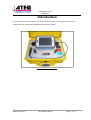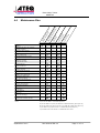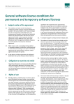
1
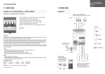
To buy, sell or trade in this product click on the link below:
http://www.avionteq.com/ATEQ-ADSE-743-Pitot-Static-Indicator-Air-Data-Tester.aspx
www.avionteq.com
Pitot Static Tester
ADSE743
ADSE743
User Manual
and
Maintenance
Reference
Edition
Date
Author
Approved by
September 2011
D2-0109-CL-D
4
13/09/11
Frédéric PLATEL
Eric Dutitre
User Manual ED 04
Page 1 of 83
Pitot Static Tester
ADSE743
Revisions
Date
Edition
Reference
Création
Octobre 2010
01
D2-0109-CL-A
Revision
01/02/11
2
D2-0109-CL-B
Revision
04/04/11
3
D2-0109-CL-C
Revision
13/09/11
4
D2-0109-CL-D
September 2011
User Manual ED 04
Page 2 of 83
Pitot Static Tester
ADSE743
Table of contents
1. PRESENTATION..................................................................................................................6
1.1 General..........................................................................................................................................6
1.2 Applications..................................................................................................................................7
1.3 Manufacturer’s part numbers....................................................................................................9
1.4 Option part Number....................................................................................................................9
1.5 Characteristics.............................................................................................................................10
1.6 Units, Range and Precision from 10°C to +40°C.....................................................................11
1.6.1
1.6.2
1.6.3
1.6.4
1.6.5
Static pressure - Ps................................................................................................................................11
Total and differential pressures - Pt - ∆P..............................................................................................11
Ps dynamic variations............................................................................................................................12
Pt dynamic variations............................................................................................................................12
Rates of intrinsic leak............................................................................................................................12
1.7 Technical description..................................................................................................................13
1.7.1 Electro pneumatique Unit......................................................................................................................14
1.7.2 Software.................................................................................................................................................18
2. USER ACCESS....................................................................................................................20
2.1 ADSE743 RCU front panel.......................................................................................................20
2.2 ADSE743 EPU front panel ........................................................................................................21
3. USE.......................................................................................................................................22
3.1 Initial Procedure.........................................................................................................................22
3.1.1
3.1.2
3.1.3
3.1.4
3.1.5
3.1.6
3.1.7
ADSE743 alternative power feeding.....................................................................................................22
ADSE743 on direct current...................................................................................................................22
Remote control link...............................................................................................................................22
Pneumatic link.......................................................................................................................................22
Preparing for use...................................................................................................................................23
Powering up...........................................................................................................................................23
Interface logiciel....................................................................................................................................23
3.2 Using the operator interface......................................................................................................24
3.2.1 Starting software....................................................................................................................................24
3.2.2 Access to the flight domains..................................................................................................................27
3.2.3 Access to the Measure/Manual Mode ..................................................................................................32
3.2.4 Automatic program mode......................................................................................................................41
3.2.5 Calibration mode...................................................................................................................................67
3.2.6 General Information..............................................................................................................................70
3.2.7 Help on line............................................................................................................................................81
3.2.8 Exiting the software................................................................................................................................81
3.2.9 Keyboard configuration.........................................................................................................................82
3.3 Automatic Grounding................................................................................................................84
September 2011
User Manual ED 04
Page 3 of 83
Pitot Static Tester
ADSE743
4. ENTRETIEN.......................................................................................................................85
4.1 User code......................................................................................................................................85
4.2 Internal........................................................................................................................................85
4.3 Low Level Maintenance............................................................................................................86
4.4 Maintenance Plan.......................................................................................................................87
5. ANNEXE 1 : Alticoder Option...........................................................................................88
5.1 Purpose.........................................................................................................................................88
5.2 Implementation..........................................................................................................................88
6. ANNEXE 2 : Succion Pump Option .................................................................................90
6.1 Purpose........................................................................................................................................90
6.2 Implementation..........................................................................................................................90
7. ANNEXE 3 : Internal Battery Pack Option.......................................................................91
7.1 Purpose........................................................................................................................................91
7.2 Charge Mode.............................................................................................................................91
7.3 State of charge.............................................................................................................................91
8. ANNEXE 4 : 2 selectable Output Option ..........................................................................92
8.1 Purpose........................................................................................................................................92
8.2 Implementation..........................................................................................................................92
9. ANNEXE 6 : DC Power Option.........................................................................................93
9.1 Implementation..........................................................................................................................93
10. ANNEXE 7 : PC Option....................................................................................................93
10.1 Implementation.........................................................................................................................93
11. ANNEXE 8 : Internal Pressure and Vaccum Pump 80000 ft / 15000 ft /min Option...94
12. ANNEXE 9 : Low Speed Option.......................................................................................94
September 2011
User Manual ED 04
Page 4 of 83
Pitot Static Tester
ADSE743
Introduction
The purpose of this manual is to provide the user with the information required to
implement and operate the ADSE743 Pitot Static Tester.
General view of ADSE743
September 2011
User Manual ED 04
Page 5 of 83
Pitot Static Tester
ADSE743
1. PRESENTATION
1.1
General
The ADSE743 pressure controller is housed in a very robust housing box, able to be
moved directly to the aircraft on the tarmac or in the hangar to proceed « in situ » to the
tests of equipment fitted to the aircraft.
The two parts of ADSE 743:
The Electro Pneumatic Unit (EPU) includes the computer, the pressure
measurement and regulation devices, the security systems as well as the pressure
and vacuum pumps necessary for independent operation in generation mode,
The Remote Control Unit (RCU), located in the cover of the housing box,
includes the Man Machine Interface. It consists of a Tablet PC fitted with a
watertight touch sensitive plate displaying the static (Ps) and total (Pt) pressure
parameters (functions, measurement units, commands, rate of change, nominal
values, program number, flight limit number).
The ergonomics of the ADSE743 caters for:
Excellent readability of the information,
Easy programming of the configuration (interactive
explanations and indication of potential handling errors),
Direct calibration by the user.
September 2011
User Manual ED 04
menus,
Page 6 of 83
with
Pitot Static Tester
ADSE743
1.2
Applications
The ADSE743 pressure generator/controller has been specially designed to simplify
pressure tests on equipment fitted on the aircraft (altimeter, air speed indicator, rate of
climb indicator, air data computers ...) would it be in the workshop, in the hangar or
directly on the tarmac.
The computer manages the security systems, the measurement and regulation devices
from the remote control unit with following operating functions:
In "Measure" or "Manual" mode, independently or simultaneously on both static
(Ps) and total (Pt) pressure channels:
◦ Measurement or generation of static (Ps) pressures (altitude),
◦ Measurement or generation of total (Pt) pressures (air speed /MACH
number),
◦ Chronometric measurement of leak rate.
In "Program" mode, independently or simultaneously on both static (Ps) and total
(Pt) pressure channels:
◦ « Flight domains » writing,
◦ « Automatic test » programs writing,
◦ Execution of the written programs. In this mode, the operator can
choose to enter at each program step the actual data read on the
equipment under test, or to let the program run and to note manually
the values read on the equipment under test.
September 2011
User Manual ED 04
Page 7 of 83
Pitot Static Tester
ADSE743
• Security:
Full time survey of all the flight domain limits parameters,
Re-connection of the pressure circuits to the atmospheric pressure
through manual flow adjustable valves in case of power supply
network cut-off,
Self test of all the ADSE743 internal functions each time the
equipment gets switched on.
• Calibration:
The calibration of the ADSE743 pressure transducers can be fulfilled
easily by the maintenance manager.
• Baro-setting:
The baro-setting (Ref) adjustment is performed by the operator
himself and remains displayed permanently.
• Altitude difference (between the bench position and the equipment under test):
The operator can introduce in the measurement process the altitude
difference between the bench on the ground and the equipment
fitted in the aircraft cockpit.
• Option available:
• Measure of Gilham code.
• Succion Pump for pitot adaptator Pitot
• Pack Battery
• 2 Channel Ps and Pt
• DC Power (19-32Vdc)
• PC cable and software to use EPU on a standard PC
• Internal pressure and vacuum80000 ft / 15000 ft/min
• Low Speed Transducer (0-200 kts)
September 2011
User Manual ED 04
Page 8 of 83
Pitot Static Tester
ADSE743
1.3
Manufacturer’s part numbers
Commercial Name
ADSE743-A CL10
HOSE-PS-10
HOSE-PT-10
CABLE-A-10
CABLE-CAD-10
1.4
Designation of materials
Ps and Pt Air Data Test Set (0,01% FS)
Red Air Hose Ps (L = 10 m)
Blue Air Hose Pt (L = 10 m)
Alternative Current Cable (L = 10 m)
Remote Control Cable (L = 10 m)
Reference
43-0001-PR-A
P4-0009-AB-D
P4-0010-AB-D
T1-0025-AB-D
T1-0024-AB-D
Option part Number
Commercial Name
BATT-PACK
V2-CHANNEL
P2-PUMP
DC-INPUT
CABLE-C-10
VS-LOW SPEED
AC-ALTICODEUR
PC-INPUT
PS-PITOT
Designation of materials
Internal Battery Pack
2 channel Ps and Pt selectable
Internal pressure and vacuum80000 ft à 15000 ft/min
DC Power 19-32V
DC Cable (L = 10 m)
Low Speed (5-200kts)
Alticodeur Input
PC cable and software to use EPU on a standard PC
Succion Pump for Pitot Adaptator
September 2011
User Manual ED 04
Reference
43-0003-PR-A
43-0004-PR-A
43-0008-PR-A
43-0009-PR-A
T1-0026-AB-D
43-0010-PR-A
43-0011-PR-A
43-0014-PR-A
43-0016-PR-A
Page 9 of 83
Pitot Static Tester
ADSE743
1.5 Characteristics
Power supply
110 V to 240 V AC from 50 to 400 Hz
And 19 V to 32 V DC (optional)
Normal operating temperature range
-5°C to + 50°C
Storage temperature
- 10°C to + 55°C
Overall dimensions of the equipment
Width
540 mm
Depth
470 mm (with bag)
Height 220 mm
Outside dimensions of the remote control Width 250 mm
unit
Depth 80 mm
Height 45 mm
Total weight (without battery, cables and
tubes)
17 kg
Weight of the RCU
1.6kg
Power consumption
September 2011
Less than
User Manual ED 04
120 VA ~
Page 10 of 83
Pitot Static Tester
ADSE743
1.6 Units, Range and Precision from 10°C to +40°C
1.6.1
Static pressure - Ps
Channe
l
Unit
Range
Ps
hPa
30 to 1200 hPa
Altitude
ft
Precision
± 0,1 hPa
Resolution
0,01 hPa
-2300 to 60 000 ft ± 3 ft at 0 ft
Zp
± 8 ft at 30000 ft
1 ft
± 32 ft at 60000 ft
m
-700 to 18 000 m
± 1 m at 0 m
± 3 m at 10 000 m
1m
± 10 m at 18 000 m
1.6.2
Total and differential pressures - Pt - ∆P
Channel
Unit
Range
Precision
Resolution
Pt
hPa
30 to 3000 hPa
± 0,25 hPa
0,01 hPa
∆P
hPa
0 to 1500 hPa
± 0,25 hPa
0,01 hPa
Speed
kts
10 to 800 kts
± 2 kt at 50 kts
Vc
± 0,14 kt at 500 kts
1 kt
± 0,07 kt at 800 kts
km/h
35 to 1480
± 3 km/h at 100 km/h
1 km/h
± 0.26 km/h at 900 km/h
± 0,13 km/h at 1480 km/h
Mach
M
0,1 to 4.0 M
± 0,0021 M at 0.8 M at
25.000 ft
0,001 M
± 0,004 M at 1.7 M at
30.000 ft
September 2011
User Manual ED 04
Page 11 of 83
Pitot Static Tester
ADSE743
1.6.3
Ps dynamic variations
Ps channel
Unit
Range
Precision
∆Ps / ∆t
hPa / min
10 to 150 hPa /
min
±1hPa or ±1 % (1)
∆Zp / ∆t (VZ)
ft / min
100 to 6000 ft /
min
±10 ft or ± 1 % (1)
m / min
30 to 1800 m / min
±3 m or ± 1 % (1)
1.6.4
Pt dynamic variations
Pt channel
Unit
Range
Precision
∆Pt / ∆t
hPa / min
10 to 150 hPa / min
±2 hPa or ± 1 % (1)
∆ ∆p / ∆t
∆ hPa / min
10 to 150 hPa / min
±2 hPa or ± 1 % (1)
∆Vc / ∆t
Kts / min
10 to 200 kts / min
±2 kts or ± 1 % (1)
∆Vc / ∆t
Kmh / min
10 to 370 kmh / min
±3,7 km/h or ± 1 % (1)
∆M / ∆t
M / min
0,1 to 1 M / min
±0,01M or ± 1 % (1)
- (1) on an integration time greater than 3 s,
− These performances are valid on a volume of 0 to 5 liter,
− The user can limit all values with «Flight limits».
1.6.5
Rates of intrinsic leak
The intrinsic leak of the ADSE743 on the two channels is maximum 0,7 hPa / 15 min at
500 hPa without outside volume.
September 2011
User Manual ED 04
Page 12 of 83
Pitot Static Tester
ADSE743
1.7 Technical description
ADSE 743 block diagram Electro Pneumatic Unit
The ADSE743 includes two parts:.
The Electropneumatic Unit
The Remote control unit.
September 2011
User Manual ED 04
Page 13 of 83
Pitot Static Tester
ADSE743
1.7.1
Electro pneumatique Unit
1.7.1.1 Front Panel
The front panel of the main box is equipped with:
One static pressure output and visualization (Red/Green),
One total pressure output and visualization (Red/Green),
One power supply connector,
One connector for the remote control unit link,
Power on visualization and Power on
One TabletPC
In option :
♦ 2 Ps and Pt Channel and visualization
♦ 1 succion output for pitot adaptator ,
♦ 1 Alticoder connectors,
♦ 1 visualization battery state.
September 2011
User Manual ED 04
Page 14 of 83
Pitot Static Tester
ADSE743
1.7.1.2 Electro-pneumatic block
Secured on a chassis below the upper plate, is situated the metrological part of the
system. The bloc includes the pressure transducers, several electro-valves, the servoloop gates, the power supply unit and the computer.
1.7.1.3 Pressure transducers
Pressure transducers are of the newest technology ensuring best accuracy.
The pressure sensors result from the last technological developments ensuring a
reduction of the costs related to a manufacturing simplification. These sensors easily
resist shocks such as overpressure.
The sensors installed in the ADSE743 are guaranteed for uses of operation between 0°C
and +45°C with an accuracy of 0,01% of the full scale (with the pressure/temperature
software correction)
The two pressure transducers are connected to an electronic board that converts
frequency into pressure values.
September 2011
User Manual ED 04
Page 15 of 83
Pitot Static Tester
ADSE743
1.7.1.4
Servo-valves
The servo-valves are designed to regulate the pressure generated by the bench. This is
a dual pressure regulator. One regulator is used for regulating vacuum intake, whereas
the other is used for regulating pressure intake. The orders are transmitted via lever
acting on small valves. A motor drives this lever served in position and controlled by the
computer depending on the difference between the pressure command and the pressure
in the pneumatic system.
These servo-valves are made of aluminum whereas the sealing parts are made of silicon
rubber. Adjustment is identical for all valves, which can be replaced without the need of
any further adjustment.
Utilisation
Pression
M
Vide
Servovalve
1.7.1.5 Power supply unit
The power supply unit is multi voltage. It receives a voltage delivered by the network
(110 to 240 V AC 50 to 400 Hz and 19 to 32 V DC in option)..
September 2011
User Manual ED 04
Page 16 of 83
Pitot Static Tester
ADSE743
1.7.1.6
Computer
The computer is made of a set of electronic boards connected together by a PC 104 bus.
The set of boards constitutes a basic unit comparable to a PC microcomputer. This
configuration has been chosen with regards to the large number of software library and
development tools existing for this type of equipment.
1.7.1.7 Safety system
The ADSE743 includes mechanical and electronic safety devices.
The software indicates the negative differential pressure.
In the case of power supply cut-off of the bench, by the user or by accident, the return to
the atmospheric pressure is achieved by operating the manual “Vent” and “Balance”
valves on the front panel.
The computer permanently controls that the pressure values, altitude or air speed as well
as dynamic changes remain consistent with the chosen flight envelope.
1.7.1.8 Remote Control Unit
The remote control Unit (RCU) is a Tablet PC located in the cover of the housing with
Windows CE embedded.
The link between RCU and EPU happens through an electric cable fitted with two
watertight connectors.
September 2011
User Manual ED 04
Page 17 of 83
Pitot Static Tester
ADSE743
Software
1.7.2
1.7.2.1 Language
The EPU computer’s Software is written in Object C++ of BORLAND.
The use of this language ensures the separation of the processing and the permanent
control of the various software modules in order to obtain an irreproachable software
quality.
The following modules of the software are:
- Sensors management,
- Pressure control management,
- Security management,
- RS232 management.
The RCU Software is written in Labview and works under Windows CE Embedded.
The following modules of the software are:
- User Interface management,
- RS232 management.
1.7.2.2 Pressure control
When the execution of an instruction is required, the starting of the pressure and vacuum
pump is activated. The first step is to balance the pressure on both sides of the insulation
electro-valve. This balance is detected by an auxiliary sensor. The opening threshold is 1
hPa approximately.
When the current pressure approaches the final set point, control pressure slows down its
evolution until the complete stop. This threshold of deceleration is calculated according to
the evolution speed and the pressure.
September 2011
User Manual ED 04
Page 18 of 83
Pitot Static Tester
ADSE743
1.7.2.3 Automatic Test programs
All programs are listed in a table accessible through the “Program” menu.
Writing or editing a program: each program step is presented on a separate screen,
where the user chooses or modifies the instructions for this step (altitude, speed,
evolution to these target values, leak test...)
1.7.2.4 Flight Domain
All information requested to write or edit a flight domain (altitude, rate of climb, speed
and acceleration) is presented in one screen, ensuring that keying in the requested data
is made very easy.
A table recapitulates all the written domains.
1.7.2.5 Self test
When the equipment gets turned on, an automatic test of the entire bench is performed.
If an error is detected, a message is written on the screen and the bench is unusable
until the problem disappears.
September 2011
User Manual ED 04
Page 19 of 83
Pitot Static Tester
ADSE743
2. USER ACCESS
2.1
ADSE743 RCU front panel
1.
Remote control lin cable,
2. ON/OFF Button with blue indicator,
2
1
Figure 1: ADSE743 remote control front panel
September 2011
User Manual ED 04
Page 20 of 83
Pitot Static Tester
ADSE743
2.2
ADSE743 EPU front panel
1. Power supply connector,
2. Link tablet PC connector,
3. « Ps » channel
4. « Pt » channel,
5. Green led to indicate the atmospheric pressure in the channel and red in
the other case
1
3
2
5
4
Figure 2: ADSE743 main box front panel
September 2011
User Manual ED 04
Page 21 of 83
Pitot Static Tester
ADSE743
3. USE
3.1 Initial Procedure
3.1.1
ADSE743 alternative power feeding
For alternative current (110 to 240 V from 50 to 400 Hz), use the cable T1-0025-AB-D.
Connect the plug to the connector 1 .
3.1.2
ADSE743 on direct current
For direct current (from 19 to 32 V DC), use the cable T1-0026-AB-D. Connect the plug
to the connector 1 and the other end of the cable with respect of + and - polarity (red
wire for + and black for -).
3.1.3
Remote control link
To connect the remote control unit, use the cable T1-0024-AB-D. Connect one of the
ends in the plug on the right side of the remote control unit and the other in the plug
marked “RCU” of the front panel of the bench.
3.1.4
Pneumatic link
Take the hoses with the pneumatic plugs, Red color for Ps (P4-0009-AB-D) and Blue color
for Pt (P4-0010-AB-D). Connect them on the front panel.
Then connect the hoses to the instruments to be tested.
Warning: During all procedures detailed in the next pages, observe the
appropriate safety instructions and procedures stated in local orders and the
aircraft and instruments maintenance manuals.
September 2011
User Manual ED 04
Page 22 of 83
Pitot Static Tester
ADSE743
3.1.5
Preparing for use
Check the following:
3.1.6
Voltage source
Electrical connection(s)
Powering up
Set the On/Off switch on the tablet PC,
3.1.7
Interface logiciel
On the power up, the TabletPC boot on Windows CE et run the program.
September 2011
User Manual ED 04
Page 23 of 83
Pitot Static Tester
ADSE743
3.2 Using the operator interface
3.2.1
Starting software
When the software gets started, the above screen is displayed as long as the computer is
running its self test and the dialog between the servo control computer and the user
interface computer is not established.
By pressing “Cancel Connection”, the operator can interrupt the connection process. The
computer will then go to “Disconnected Mode” and will not try to connect again.
Figure 3
September 2011
User Manual ED 04
Page 24 of 83
Pitot Static Tester
ADSE743
3.2.1.1 Dialog established
As soon as the dialog is established, the information « Connected Mode » appears. All
keys on the screen become accessible to the user.
If the self test has been completed without problem, no message appears in the
information area situated at the bottom of the screen.
Figure 4
Range limits: To select, create or modify domains,
Measure / Manual Mode: To use ASDE in manual mode,
Automatic Program: To select, create, modify and execute automatic program,
Calibration : To calibrate transducer Ps and Pt,
Exit : To Exit from application and come back to Windows CE.
Note 1: The date of the last calibration is indicate on the bottom field text.
September 2011
User Manual ED 04
Page 25 of 83
Pitot Static Tester
ADSE743
3.2.1.2 Dialog not established
If the computer could not complete its self test, the dialog with the user interface
computer does not happen. The message “Mode not connected” appears.
To retry the connection:
Check that the link cable to the EPU is correctly connected on both sides and
that power is available for the EPU (red light on the front panel of the EPU).
Exit the application and restart it.
If the problem persists, contact the after sales service of ATEQ-OMICRON.
September 2011
User Manual ED 04
Page 26 of 83
Pitot Static Tester
ADSE743
3.2.2
Access to the flight domains
Press « Range limits » to access this menu. It gives access to following functions:
Select an existing flight domain,
Create a new flight domain,
Edit an existing flight domain.
Figure 6
September 2011
User Manual ED 04
Page 27 of 83
Pitot Static Tester
ADSE743
3.2.2.1 Select a flight domain.
The selection of a flight domain happens through a window presenting all existing flight
domains.
Press « Cancel » to come back to the « Range limits » main menu,
Select the desired Domains,
Press « Validate » to visualize the selected flight domain.
Figure 7
September 2011
User Manual ED 04
Page 28 of 83
Pitot Static Tester
ADSE743
Figure 8
All parameters of this flight domain appear, the user can choose between:
« Return» to return to the list of flight domains,
« Validate » to select this flight domain immediately (but this selection will be lost
at the next start of the software),
« By Default » to select this flight domain immediately and keep it as domain by
default at the start of the system.
Note 1: The flight domain called « max » is a reserved flight domain and can
neither be modified nor deleted.
September 2011
User Manual ED 04
Page 29 of 83
Pitot Static Tester
ADSE743
3.2.2.2 Creating a flight domain
The range limits creating mode is accessible through a password.
Upon creation of a flight domain, the value fields are pre-programmed with the maximum
values acceptable by your ADSE743.
The user must:
Enter a domain name by clicking on the field, which gives access to an
alphanumeric keyboard,
Modify the values by using the digital keyboard which appears by clicking on
the associated field.
Once all parameters are entered, press « Save » to validate and record the data or press
« Return » to abandon the flight domain creation and come back to the « Range limits »
main menu.
Figure 9
September 2011
User Manual ED 04
Page 30 of 83
Pitot Static Tester
ADSE743
3.2.2.3
Editing a flight domain
The range limits editing mode is accessible through a password.
Editing a flight domain happens through a window presenting all existing flight domains
(except « max »).
« Return » to come back to the « Range limits » main menu,
« Validate » to edit the selected flight domain.
All parameters of this flight domain appear; the user can modify the values by using the
digital keyboard which appears by clicking on the associated field.
Figure 10
After entering the data, press
« Return » to come back to the « Range limits » main menu,
« Save » to record the selected flight domain.
September 2011
User Manual ED 04
Page 31 of 83
Pitot Static Tester
ADSE743
3.2.3
Current
Unit
Access to the Measure/Manual Mode
Gap Altitude
between ADSE and
pitot tube
State of ADSE
Reference for Altitude
Don't stop
generation if
leak or big
volume
Activating
Channel
To Execute a
set point
Select unit
Ps
Step by
step
increment
Or Alticoder
Information
Select Unit
Pt
To visualize
Domain
To make
leak test
To go back at
Ground
To Stop
Generation
To visualize
The User
Manual
Back To main
Menu
Figure 11
September 2011
User Manual ED 04
Page 32 of 83
Pitot Static Tester
ADSE743
In this Mode, the operator can access to:
Manual Mode : Access to the unit, pressure information, generation mode,
Leak test : To run Leak test on PS and Pt
Domain: To view the current domain
Help : To view the Help in line
On each channel (Ps and Pt), the user can:
Change the pressure unit with the scrolling menu.
Activate or disactivate the channel, in order to access the instruction fields
for a generation, a leak test...
Enter the generation instructions,
Launch a generation,
Increment the instructions step by step in the selected unit,
Move to the Leak test function,
Come back to the ground,
Stop a generation.
Note 1:
Mode Big Capicity: This mode is used when you have a big volume and the rate of climb
is not an important parameter. In this case, the ADSE regulate the desired rate of climb
until possible and decrease this parameter to continu. In the standard case, the ADSE
stop generation if one parameter can not be respect.
September 2011
User Manual ED 04
Page 33 of 83
Pitot Static Tester
ADSE743
3.2.3.1 To change unit on Ps and Pt
To change the unit, press the « Alt. » button (for the Ps channel) or « Speed » button
(for the Pt channel) and select the unit from the scrolling list.
The change is active when the requested unit appears in the field « Actual unit ». The
pressure evolution is then displayed in the new selected unit.
Important notice: a unit change does not result in an update of the target and rates
values, due to the non linearity between pressure units on one side and altitude and
speed units on the other side.
Unit Ps: hPa, Psi, mmHg, inHg, ft, m...
Figure 12
September 2011
User Manual ED 04
Page 34 of 83
Pitot Static Tester
ADSE743
Unit Pt: hPa, Psi, mmHg, inHg, DhPa, DPsi, DmmHg, DinHg, Kts, km/h, MPH,
Mach...
Figure 13
3.2.3.2 Activating a channel
Activating or disactivating a channel happens by clicking on the « Ps » or « Pt » button. A
green or red light and a message indicate the status of the channel:
If the channel is active, the light is green and the message displayed is « Channel
ON ».
If the channel is inactive, the light is red and the message displayed is « Channel
OFF ».
September 2011
User Manual ED 04
Page 35 of 83
Pitot Static Tester
ADSE743
Activating a channel gives access to the instruction fields and to the « Execute »,
« Leak » and « Ground » functions.
When a channel is inactive and will not be used during a generation, it is recommended
to leave the corresponding outlet open, in order to keep the internal pressure of this
channel equal to the ambient pressure.
Warning: The function of generating on Ps and leaving the Pt channel inactive should be
used with major care, especially when the static circuit of the aircraft is pneumatically
linked to the airspeed indicator: generating on Ps will cause the airspeed indicator to
climb, potentially outside its range limits.
3.2.3.3 Generating on the Ps or Pt channel
To perform a generation,
Active the channel,
Select the desired unit
Enter the altitude (for Ps) or speed (for Pt) value and the climb rate (Ps) or
acceleration (Pt):
◦
Select the instruction field. This field will flicker in red.
◦
Enter the desired value with the keyboard. Repeat this operation with the
« Rate » field.
If one of the values entered is outside the flight domain, a message “Domain overflow”
will appear at the bottom of the screen and the value will be forced to the closest value
within the flight domain (either min or max value within the flight domain, depending
whether the entered value was below or over the allowable values).
Executing the instruction
In order to execute the instruction, click on « Execute ». The data entered in the
instruction fields of the active channels are taken into account and the ADSE743 starts
generating.
Different messages appear during the different phases of the generation.
Before the generation starts, the message indicates « Reader »: the ADSE
September 2011
User Manual ED 04
Page 36 of 83
Pitot Static Tester
ADSE743
is in slave mode and displays the pressure without controlling it.
When the generation starts, the ADSE will manage the evolution of the
pressure. During the first phase, the tester will start the pumps (message
displayed: “Starting”), then balance the pressure internally to avoid a
pressure surge (Message displayed: « Balancing »).
During the next phase, the pressure will evolve at the set rate to reach the
set target. The message displayed indicates « Run ».
During the last phase, the pressure is stabilized at the set target. The
message displayed indicates « Ready ».
Note #1: In execution mode, the automatic increment of the target is accessible. By
using this function, the operator can increment or decrement the target pressure by the
value indicated between the « + » and « -» buttons. By clicking the « + » or « - »
button, the operator increases or decreases the target value. The ADSE 740 updates the
display of the instructions accordingly and starts generating the pressure according to
this new target. To modify the increment step, click on the corresponding field and enter
the requested value with the keyboard.
Note #2: If you change an instruction during the generation, click on « Execute » to
request the generator to take this new value into account.
Note #3: When both channels are active, clicking on « Execute » requests the generation
on both channels simultaneously. In this case, the generation starts first on the Pt
channel. When the rate is stabilized on Pt, the generation starts on Ps.
Note #4: If the operator clicks “Execute” without having entered a value in the “Rate”
field, the system will display the message “Domain overflow” and force the rate to the
minimum value.
September 2011
User Manual ED 04
Page 37 of 83
Pitot Static Tester
ADSE743
3.2.3.4
Leak test
When the operator switches to the Leak test mode, the ADSE moves automatically to the
« Reader » mode on both channels. The unit for the leak test is the unit selected in the
main menu of the manual mode.
To access this screen, click on the « LEAK » button of the manual mode menu.
Figure 14
To configure the test, enter a time. Click on the minutes and seconds field and enter the
values with the keyboard.
To launch the leak test, click on « Start ». The time starts being counted down until 0
minute and 0 second. The leak is displayed in the « Leak » field.
During the test, the fields « Value » and « Rate » evolve. The operator can stop the leak
test at any time by clicking on the « Stop » button.
To come back to the main screen of the manual mode, click on the « MANUAL » button.
September 2011
User Manual ED 04
Page 38 of 83
Pitot Static Tester
ADSE743
The ADSE743 returns to the generation mode.
Important notice: if a unit change has been performed, the set targets might be
inconsistent with the units. Recheck carefully the set values before starting a generation.
Note:
For pressure unit (hPa, Psi ...):
Result = Finale Pressure – Initial Pressure
For altitude and airspeed unit (ft, m, kts, Mach...):
Result = Initial value – Final Value
3.2.3.5 Return to the ground
When the operator clicks on « Ground », the ADSE743 compares the ambient pressure
with the pressures in the Ps and Pt circuits. If on one of the channels, the pressure is
different, the ADSE743 turns to the generator mode and returns to the atmospheric
pressure in the selected unit and using the last rate entered. The message « Back to
Ground» is displayed at the bottom of the screen
Once the internal pressure has reached the ambient pressure, the ADSE turns to the
« Reader » mode and opens the internal circuit to the ambient pressure. The message
« Atmosphere » is displayed at the bottom of the screen. The equipment in test can be
securely disconnected from the ADSE743.
Note: When the system is back to ground (“Atmosphere” displayed on both channels)
the operator has access to:
The correction of Qfe: Choice between 1013.25 hPa and atmospheric
(local) pressure as reference for altitude simulation.
The correction for altitude gap: Parameter in feet or meter equal to the
difference between the measurement of the pressure at the level of the
test set (Ps outlet) and the altimeter situated in the aircraft.
September 2011
User Manual ED 04
Page 39 of 83
Pitot Static Tester
ADSE743
3.2.3.6 Displaying the current flight domain
Figure 15
At any time, the operator can click on the « Domain » button to display the flight domain
currently in use.
To return to the main screen, click on the « Back» button.
September 2011
User Manual ED 04
Page 40 of 83
Pitot Static Tester
ADSE743
3.2.4
Automatic program mode
The program mode allows the user to create, visualize, edit and start an automatic test
program.
Figure 16
September 2011
User Manual ED 04
Page 41 of 83
Pitot Static Tester
ADSE743
3.2.4.1 Writing a new program
The program writing mode is accessible through a password.
Steps for writing a flight program:
Click on “New Program”. This gives access to the screen shown on Figure 17
Figure 17
Enter a file name by clicking on the field, in order to have access to the alphanumerical keyboard. The list of existing files is given for information.
When the “Validate” button is clicked, a consistency check is performed.
◦
If the field is empty, the application returns to the main menu
◦
If the program name already exists, a dialog box is displayed, indicating
the problem. After validation, the user is requested to enter a new name.
September 2011
User Manual ED 04
Page 42 of 83
Pitot Static Tester
ADSE743
Write a program with a maximum of 40 steps
To save the data, click on « Save »,
To delete a current program step, click on « Delete (Step) »,
To insert a step before the step displayed, click on « Insert (Step) »,
To Add a step click on « --> »
To cancel the creation of the program, click on «Main Menu».
Measure Mode:
Figure 18
September 2011
User Manual ED 04
Page 43 of 83
Pitot Static Tester
ADSE743
Generation Mode:
Figure 19
Leak Test Mode:
Figure 20
September 2011
User Manual ED 04
Page 44 of 83
Pitot Static Tester
ADSE743
Ground Mode:
Figure 21
"Measure" Mode : The ADSE743 switches to the pressure measure mode and
stops regulating the pressure. In this mode, the measurement unit can be
chosen, in which the information shall be displayed, as well as the level time
before the program goes to the next step.
"Generation" Mode: In this mode, the altitude or speed value, the climb or
acceleration rate and the measurement unit used for the generation need to
be entered. Once the generation level has been reached, the level time
entered by the user is counted down before the program goes to the next
step.
September 2011
User Manual ED 04
Page 45 of 83
Pitot Static Tester
ADSE743
"Leak" Mode: In this mode, the ADSE743 switches into measure mode,
waits until the pressure stabilizes in the circuit during a time corresponding to
the level entered by the user, then starts the leak test entered in the
« Time » field and in the entered measurement unit. Once the time has been
counted down, the user is requested to validate, so that the program
continues to the next step.
"Ground" Mode: The ADSE743 automatically comes back to the ground,
using the last measurement unit and the last rate of climb validated, and
then opens the electro-valve putting the circuit at atmospheric pressure. If
the generator is already at atmospheric pressure (+/- 5 hPa), only the
electro-valve opening to the atmospheric pressure is activated. Once the
ADSE743 has reached the atmospheric pressure, the level time entered by
the user is counted down before the program goes to the next step.
Note 1: In the case of a request to return to ground, when no generation has been
performed before but the generator is at a pressure different from the atmospheric
pressure, the equipment comes back to the ground using the hPa as measurement unit
and a climb rate equal to 100 hPa/min.
September 2011
User Manual ED 04
Page 46 of 83
Pitot Static Tester
ADSE743
3.2.4.2 Visualizing and editing a program
Figure 22
Click on “Read/Edit Program” on the Automatic Program menu
(Figure 16),
Select the desired program,
The screens displayed are identical to the screens of the creation
mode. The user can edit the program, delete or modify existing
steps or add new steps.
To save the modifications, click on « Save », and enter the right
password.
September 2011
To quit without saving, click on « Menu ».
User Manual ED 04
Page 47 of 83
Pitot Static Tester
ADSE743
3.2.4.3 Executing a program
Important Notice : Before starting a program, it is recommended to make sure
that the test set is at ground level:
Select “Measure / Manual Mode” in the main menu:
Return the system back to the ground (“Atmosphere” displayed on both
channels),
Figure 23
September 2011
User Manual ED 04
Page 48 of 83
Pitot Static Tester
ADSE743
Figure 24
Figure 25
September 2011
User Manual ED 04
Page 49 of 83
Pitot Static Tester
ADSE743
Figure 26
Figure 27
September 2011
User Manual ED 04
Page 50 of 83
Pitot Static Tester
ADSE743
Figure 28
Figure 29
September 2011
User Manual ED 04
Page 51 of 83
Pitot Static Tester
ADSE743
Figure 30
Figure 31
September 2011
User Manual ED 04
Page 52 of 83
Pitot Static Tester
ADSE743
Figure 32
Figure 33
September 2011
User Manual ED 04
Page 53 of 83
Pitot Static Tester
ADSE743
Figure 34
Figure 35
September 2011
User Manual ED 04
Page 54 of 83
Pitot Static Tester
ADSE743
Figure 36
September 2011
User Manual ED 04
Page 55 of 83
Pitot Static Tester
ADSE743
3.2.4.3.1
Operating Mode
Click on “Start Program” (Figure 16) to access screen shown on Figure 23
Select a test program in the list of existing programs and « Validate »,
A configuration window (Figure 24) appears to:
◦
Enter a number of loops (number of times you want the program to repeat).
◦
Select the pressure reference (Choice between 1013.25 hPa and local (Qfe)
pressure.)
◦
Enter the altitude gap between the test set (Ps outlet) and the altimeter
situated in the aircraft. For example, if the altimeter is 10 feet above the test
set, enter “10”. If it is 10 feet below the test set, enter “-10”.
◦
Select automatic (Figure 24) or semi automatic (figure 25) program. In semi
automatic mode, the test set pauses after each program step. The operator
can enter the values read on the instruments as well as comments, separately
for the Ps and the Pt channels. These data (value and comments) are saving
in a spreadsheet (see next paragraph).
Validate to start program.
The step nr. 1/x is displayed with the program Loop nr. 1/y and the name of the
selected program (figure 26)
Click on « Execute » to start the program.
The step nr.1 of the loop nr.1 is displayed and executed and so forth until step
nr. x/x and Loop nr. y/y for the automatic mode.
September 2011
User Manual ED 04
Page 56 of 83
Pitot Static Tester
ADSE743
Note 1: In semi automatic mode, at the end of each step, two buttons “Edit Ps” and “Edit
Pt” appear (Figure 27) to enter the value shown on the altimeter and/or airspeed
indicator and comments (Figure 28). To resume the program, press “Execute”.
Note 2: At any time, the user can switch to the standby mode by clicking on « Pause ». If
the generator is counting down a level time, the “Pause” instruction will be taken into
account at the end of the countdown. To resume the execution of the program, click on
“Execute” (Figure 27).
Note 3: At the end of a program, the user can exit the program by clicking on « Menu »
or re-launch the program by clicking on « Exec ».
Note 4: At any time, the currently selected flight domain can be visualized by clicking on
“Domain”.
September 2011
User Manual ED 04
Page 57 of 83
Pitot Static Tester
ADSE743
3.2.4.3.2
program
File format for the data recorded by the semi-automatic
At the end of the semi automatic mode, a text file, formatted to be opened with Excel, is
created in the directory “C:\ADSE 743\Results\” with the format “XXXX YYYY ZZZZ.txt”
where XXXX is the Name of program, YYYY corresponds to the date and ZZZZ
corresponds to the time.
This example shows the “TOTAL 23_09_2010 05_49_34_PM.txt” file program opened
with Excel.
This file is accessible by users allowed to access the underlying Windows XP operating
system (see 3.3.11: Exiting the software). From there, the remote control unit is useable
as a normal Windows PC.
Figure 37
September 2011
User Manual ED 04
Page 58 of 83
Pitot Static Tester
ADSE743
3.2.4.3.3
Spreadsheet cells content
“A1”: Program name
“A4”: Date of test
“A5”: Time of test beginning
“A8”: Field Name on Figure 25
“A11”: Field Comments on Figure 25
“A16”: Pressure reference configuration
“A19”: Altitude gap between the test set and the aircraft altimeter (as
entered on the screen on Figure 25)
Line “25 to xx”: Information step by step:
◦
Column A: “Ps Mode” ->Measure, Manual, Leak, Ground
◦
Column B: “Ps Value” ->Set point for altitude
◦
Column C “Ps Rate” ->Set point for rate of climb
◦
Column D “Ps Unit” ->Unit used for the altitude
◦
Column E “Ps Read” ->Value entered by the operator (or automatically
in Leak mode in the unit used)
◦
Column F “Ps Comments” ->Comments entered by the operator
◦
Column H: “Pt Mode” ->Measure, Manual, Leak, Ground
◦
Column I: “Pt Value” ->Set point for airspeed
◦
Column J “Pt Rate” ->Set point for acceleration
◦
Column K “Pt Unit” ->Unit used for speed
◦
Column L “Pt Read” ->Value entered by the operator (or automatically
in Leak mode in the unit used)
◦
Column M “Pt Comments” ->Comments entered by the operator
◦
Column O “Time Leak Minute” ->Indicates the leak test duration
(minutes)
◦
Column P “Time Leak Second” ->Indicates the leak test duration
(seconds)
September 2011
User Manual ED 04
Page 59 of 83
Pitot Static Tester
ADSE743
3.2.5
Calibration mode
The calibration mode is accessible through a password.
The first step is to validate the date or enter the right date.
Figure 38
Choose the channel to be calibrated (Ps or Pt),
Figure 39
September 2011
User Manual ED 04
Page 60 of 83
Pitot Static Tester
ADSE743
3.2.5.1
Calibrating the sensors
Calibrating the sensors of the ADSE743 requires a pressure standard in a climate
controlled room with a temperature regulated between 20 and 25°C.
Place the ADSE 743 in the climate controlled room, next to the pressure
standard,
Turn it on,
Leave the equipment for at least 30 min to stabilize in temperature.
3.2.5.2 Operating mode
Choose the channel to be calibrated (Ps or Pt),
Figure 40
Different information are displayed on the screen:
The serial number of the sensor
The uncorrected pressure measured by the sensor in the « Measure » field.
Three buttons are accessible as well as a data entry field « Standard ».
September 2011
User Manual ED 04
Page 61 of 83
Pitot Static Tester
ADSE743
The calibration procedure consists of:
Generating controlled pressures with a pressure/vacuum generator connected on
one of the Ps or Pt pneumatic connectors and to a pressure standard,
Reading the value of the pressure standard and entering it in the « Standard »
field with the digital keyboard which appears by clicking in this field.
Click on “Validate Measure” to Validate the value entered.
Validating the calibration once all points (pressure values) have been entered, by
clicking on «Validate calibration».
When the calibration is validated:
The data are saved in a backup file,
The data are sent to the computer which takes into account these new
parameters.
To obtain an optimal calibration of the equipment, ATEQ-OMICRON recommends to
perform the calibration by measuring following pressure values:
On the Ps channel: 25, 50, 100, 200, 300, 400, 500, 600, 700, 800, 900, 950,
1000, 1050, 1100, 1200 hPa.
On the Pt channel: 25, 50, 100, 200, 300, 400, 500, 600, 700, 800, 900, 1000,
1100, 1200, 1300, 1400, 1600, 1800, 2000, 2200, 2400, 2600 hPa.
Note 1: The user can enter up to 40 pressure values per channel on the whole scale.
These data must be entered starting from the minimum pressure upwards to the maximal
pressure.
When the data have been successfully transferred to the computer, a message
« Calibration OK » appears in the information window. If the transfer did not happen
properly, a message « Calibration KO » appears. The data need to be loaded again.
Click on the button « Load data ». To validate the data transfer, click on « Validate »
otherwise click on « Cancel ».
The data transfer procedure resumes.
Note 2: If a calibration validation is requested but less than two calibration points have
been validated, a control prohibits this validation and an information window is displayed.
September 2011
User Manual ED 04
Page 62 of 83
Pitot Static Tester
ADSE743
3.2.6
General Information
By clicking on the « Config» button of the main menu, following information is displayed:
Figure 41
« Main Menu» brings back to the main menu,
« Help » opens an HTML Help for the user,
« Parameters » gives access to the modification of:
the password requested to exit the remote control unit software (access to
the underlying operating system), to access the calibration mode, to write
and to modify a program and a flight domain,
Calibration of the Touch screen
Sound Management
Backligth Management
Update Management software,
« Languages » allows to change yhe language of the software
September 2011
User Manual ED 04
Page 63 of 83
Pitot Static Tester
ADSE743
3.2.6.1
Parameters
Figure 42
« Password » : To modify password,
« Touchscreen » : To calibrate the touchscreen,
« Beep » : Green Button for sound « ON » and Grey to sound «OFF »,
« Stand by » : Button grey, backlight always 100%, and green, you can
configure:
•
« Backlight max » : to configure the power of backlight (50 to
100%),
•
« Backlight min » : to configure the power of baclight (0 to
Backlight max),
•
« Wait (min) » : Time between backlight max and min without
touch,
Update Management software.
September 2011
User Manual ED 04
Page 64 of 83
Pitot Static Tester
ADSE743
3.2.6.1.1
Password
By default,when the equipment is delivered, the password is the serial number of the
equipment.
3.2.6.1.1.1 Changing a password
By clicking on the « Config» button of the main menu and « Parameters », following
information is displayed:
Figure 43
Figure 44
September 2011
User Manual ED 04
Page 65 of 83
Pitot Static Tester
ADSE743
Figure 45
Figure 46
September 2011
User Manual ED 04
Page 66 of 83
Pitot Static Tester
ADSE743
Select “Calibration” to change the password of calibration Mode or “By default” to
change the other password (To write or modify program, domain, to exit).
Enter the current password by clicking in the field and using a alpha numeric
keyboard,
If the password entered is wrong, a message appears : « Incorrect password »,
If the password is correct, a window appears, where the user is requested to enter
twice the new password and validate (Figure 44 and 45),
If both passwords are different, an error message “The passwords are different” is
displayed,
If the passwords are identical, a window appears, requesting to validate the
change (Figure 46),
If the user clicks on « Return » without validating, the change is not taken into
account.
September 2011
User Manual ED 04
Page 67 of 83
Pitot Static Tester
ADSE743
3.2.6.1.1.2
Enter a password
Figure 47
When a password is requested:
click on the field,
enter the current password by using the alphanumeric keyboard.
Validate to continu or Cancel to back to the main menu
September 2011
User Manual ED 04
Page 68 of 83
Pitot Static Tester
ADSE743
3.2.6.2 Languages
Figure 48
To change Languages:
Select the desired Languages,
Press « Validate » to change.
September 2011
User Manual ED 04
Page 69 of 83
Pitot Static Tester
ADSE743
3.2.7 Help on line
The « HELP » button on the main menu open a html windows with the user manual.
3.2.8 Exiting the software
To exit to the software and come back to Windows CE, click on « Exit » in the main menu.
And enter a password.
September 2011
User Manual ED 04
Page 70 of 83
Pitot Static Tester
ADSE743
3.2.9
Keyboard configuration
To enter a numeric or an alpha-numeric value, 3 kind of keyboard apppear.
3.2.9.1 Digital keyboard
To enter a digital value, this screen is displayed:
Figure 49
Enter a value and validate by "ENTER" or escape by “ABORT”.
September 2011
User Manual ED 04
Page 71 of 83
Pitot Static Tester
ADSE743
3.2.9.2
Alpha-Numeric Keyboard
To enter an alphanumeric value, this screen displayed:
Figure 50
Enter an alphanumeric value and validate by "Enter" or escape by “Escape”
Note: For password, Text is masked as follow:
Figure 51
September 2011
User Manual ED 04
Page 72 of 83
Pitot Static Tester
ADSE743
3.3
Automatic Grounding
If the ADSE743 can not generate pressure to go back to the ground, turn off ADSE743,
your equipment back to local pressure automatically.
September 2011
User Manual ED 04
Page 73 of 83
Pitot Static Tester
ADSE743
4. ENTRETIEN
4.1 User code
The initial user code (upon delivery of the equipment) necessary to access some secured
menus is the serial number of the equipment.
4.2
Internal
Your ADSE 743 is conceived to give you full satisfaction for a large number of years. As it
contains some components potentially subject to ageing (filters, membranes...) we
recommend to follow the maintenance plan in the appendix, in order to ensure a perfect
operation on the long run.
This maintenance plan is valid for a use in normal conditions of temperature, dust,
moisture and salt, with only occasional use in very harsh environment. In the case of a
permanent use in harsh conditions (equipment embarked permanently on an aircraft
carrier, on an airbase in the desert...) we recommend to divide by two the time between
two maintenances.
September 2011
User Manual ED 04
Page 74 of 83
Pitot Static Tester
ADSE743
4.3
Low Level Maintenance
Housing: Clean every month with soft sponge (water and mild liquid detergent)
Front panels and touch screen: Clean every week with damp lint-free cloth and mild
liquid detergent.
Note : NEVER USE AGRESSIVE DETERGENT OR SOLVENT
Electric Cable : Check the cable and connector before each used.
Pneumatic hose : Check hose and plug before each used.
Internal Leak: Check every month the internal leak of the ADSE as describe chapter
3.2.3.4.
September 2011
User Manual ED 04
Page 75 of 83
Pitot Static Tester
ADSE743
Maintenance Plan
La
b
Ag orat
ree oir
dL ea
ab gré
é
or
om ou o
Ce
m
ic r
n
on ic ro
Ag tre
n
ree de
rép
dr
ep
air arat i
c e on
nt e ag
Ch
r o rée
Ev aque
ro
o
ery
m i u om
an
c ro
n
ye
ée
ic r
n
ar
on
To
us
Ev
l
ery es d
t w eux
oy
a
ea ns
rs
To
us
Ev
l
ery es 4
f o ans
ur
ye
ars
4.4
Calibration
Calibration
Changement des f iltres de v entilation
Fan f ilters exchange
Changement f iltres internes
Internal f ilters exchange
Vérif ication alimentation interne
Internal v oltage check
Vérif ication pneumatique interne
Internal pneumatic check
Changement des pièces en caoutchouc
Rubber part exchange
Test des électrov annes
Electrov alv es test
Test cartes électroniques
Electronic board test
Test connecteurs pneumatiques
Pneumatic plug test
Test connecteurs électriques
Electric plug test
Réglage v anne modulante
Regulation v alv e adjustment
Remplacement dalle tactile
Touch screen exchange
Rénov ation des électrov annes
Electrov alv es renov ation
Remplacement connecteurs pneumatiques
Pneumatic plug exchange
Test groupe de pompage
Pump group test
Changement v entilateurs
Fan exchange
Test des batteries
Battery test
Changement des batteries
Battery pack exchange
Rénov ation des électrov annes 3Ps 3Pt
Electrov alv es renov ation 3Ps 3Pt
Notes:
X
X
X
X
X
X
X
X
X
X
X
T
X
X
P
X
B
B
M
X
X
X
X
X
X
X
X
X
X
X
T
X
X
P
X
B
B
M
X: pour tous les ADSE / f or all ADSE equipment
B: pour les ADSE av ec option pack batterie/ f or ADSE with battery pack option only
M: pour les ADSE av ec option multi-v oies / f or ADSE with multiple outlet option only
P: pour ADSE av ec pompes internes / f or ADSE with internal pumps only
T: pour ADSE av ec écrans tactiles / f or ADSE with touch screen
September 2011
User Manual ED 04
Page 76 of 83
Pitot Static Tester
ADSE743
5.
ANNEXE 1 : Alticoder Option
5.1 Purpose
This option is composed by an electronic board whose read Gilham code on Alticoder and
gives the information in the Manual mode of the software
5.2
Implementation
Make the cable to link Alticodeur and ADSE.
○
Take a SOURIAU connector Reference: UTS6JC14E19P
○
Follows this array to manufacture the cable:
Pin number Souriau
Signal Name
A
B
C
D
E
F
G
H
J
K
L
M
N
P
R
S
T
U
V
A1
A2
A4
B1
B2
B4
C1
C2
C4
D1
D2
D4
+5V
GND
NC
NC
+12V
+24V
LOOP GND
LOOP GND must be connected to GND
Note : 5Vdc / 800mA, 24Vdc/800mA and 12Vdc/800mA are available to the
power supply of the Alticodeur.
September 2011
User Manual ED 04
Page 77 of 83
Pitot Static Tester
ADSE743
Plug the cable between ADSE and Alticoder.
In the « Measure/ Manual » Mode of the software, the information of the alticoder
must be present on the right of PS channel. If the information is « --- », the cable
is detected but there is a problem with the Alticoder:
○
Alticoder not connected,
○
Gilham Code erroe or not reading,
Note: If no field Alticoder appear on the screen, check the cable.
September 2011
User Manual ED 04
Page 78 of 83
Pitot Static Tester
ADSE743
6.
ANNEXE 2 : Succion Pump Option
6.1
Purpose
To fixe Pitot adaptator with suction cup, a output succion is available to maintain the
pneumatic pressure between 600 and 700 hPa.
6.2
Implementation
Plug Hose on the pitot adaptator and on the ADSE output succion,
Push on the Succion button ,
The vaccuum pump is on and regulate automatically the pressure.
Note : If the succion pump is always ON, verify leak on a pneumatic circuit.
September 2011
User Manual ED 04
Page 79 of 83
Pitot Static Tester
ADSE743
7.
ANNEXE 3 : Internal Battery Pack Option
7.1
Purpose
This option include a battery pack (24Vdc / 8AH) with management board.
2 kind of using:
No power supply available, the ADSE743 run only on battery.
The ADSE743 run with an external power supply. The power supply « cut off » and
battery switch on automatically and maintain the ADSE ON.
When the AC power is connected on the ADSE, the battery pack is in charge
A full charge can last 3H.
7.2
Charge Mode
Plug the AC Power on the ADSE
The battery led management is red. Battery is on charge.
The battery led Management is green, battery is charged.
7.3
State of charge
When the ADSE run on battery, the user can view the state of charge. Push the
button Battery to tun on the battery led Management
−
Green
: Charge Between 50 and 100%,
−
Orange
: Charge between 10 an 50%,
−
red
: Battery discharged,
September 2011
User Manual ED 04
Page 80 of 83
Pitot Static Tester
ADSE743
8.
ANNEXE 4 : 2 selectable Output Option
8.1
Purpose
This option allows to connect 2 independent pneumatic circuit Ps and Pt on the ADSE and
make test independently.
8.2
Implementation
Plug the pneumatic circuit,
Turn on the ADSE, and go in « the Measure/ Manual Mode »
Return to the ground, « Atmosphere » displayed on both channels
Choose the Channel « V1 » or « V2 », by clicking on the desired channel
(Green=Channel open, led off= channel closed)
.
September 2011
User Manual ED 04
Page 81 of 83
Pitot Static Tester
ADSE743
ANNEXE 6 : DC Power Option
9.
This option allows the ADSE to run with an External DC power.
9.1
Implementation
Plug DC Cable « T1-0026-AB-D » on the ADSE,
Plug an external DC power (19-32V / 10A) ,
Turn on the ADSE.
Note1: In this mode the battery don't charge.
10. ANNEXE 7 : PC Option
With this option a standard PC is used to manage ADSE. It's composed to a specific cable
to link ADSE to the USB and a software
10.1 Implementation
Setup the software on the PC,
Plug the specific cable « EZ-020-A » betwween the ADSE and the PC,
Turn on the ADSE,
Run the software.
September 2011
User Manual ED 04
Page 82 of 83
Pitot Static Tester
ADSE743
11. ANNEXE 8 : Internal Pressure and
Vaccum Pump 80000 ft / 15000 ft /min
Option
With this option, the user can test materials at 80000 ft with 15000 ft/min in rate of
climb.
12. ANNEXE 9 : Low Speed Option
This option is reserved for the speed between 0 and 200 Kts. To ,improve precision, the
ADSE is equiped with a specific transducer
September 2011
User Manual ED 04
Page 83 of 83