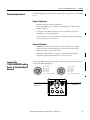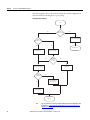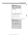
1
User Manual
EtherNet/IP-to-DeviceNet Linking Device
Catalog Numbers 1788-EN2DNR, 1788-EN2DNROM
Important User Information
Read this document and the documents listed in the additional resources section about installation, configuration, and
operation of this equipment before you install, configure, operate, or maintain this product. Users are required to
familiarize themselves with installation and wiring instructions in addition to requirements of all applicable codes, laws,
and standards.
Activities including installation, adjustments, putting into service, use, assembly, disassembly, and maintenance are required
to be carried out by suitably trained personnel in accordance with applicable code of practice.
If this equipment is used in a manner not specified by the manufacturer, the protection provided by the equipment may be
impaired.
In no event will Rockwell Automation, Inc. be responsible or liable for indirect or consequential damages resulting from the
use or application of this equipment.
The examples and diagrams in this manual are included solely for illustrative purposes. Because of the many variables and
requirements associated with any particular installation, Rockwell Automation, Inc. cannot assume responsibility or
liability for actual use based on the examples and diagrams.
No patent liability is assumed by Rockwell Automation, Inc. with respect to use of information, circuits, equipment, or
software described in this manual.
Reproduction of the contents of this manual, in whole or in part, without written permission of Rockwell Automation,
Inc., is prohibited.
Throughout this manual, when necessary, we use notes to make you aware of safety considerations.
WARNING: Identifies information about practices or circumstances that can cause an explosion in a hazardous environment,
which may lead to personal injury or death, property damage, or economic loss.
ATTENTION: Identifies information about practices or circumstances that can lead to personal injury or death, property
damage, or economic loss. Attentions help you identify a hazard, avoid a hazard, and recognize the consequence.
IMPORTANT
Identifies information that is critical for successful application and understanding of the product.
Labels may also be on or inside the equipment to provide specific precautions.
SHOCK HAZARD: Labels may be on or inside the equipment, for example, a drive or motor, to alert people that dangerous
voltage may be present.
BURN HAZARD: Labels may be on or inside the equipment, for example, a drive or motor, to alert people that surfaces may
reach dangerous temperatures.
ARC FLASH HAZARD: Labels may be on or inside the equipment, for example, a motor control center, to alert people to
potential Arc Flash. Arc Flash will cause severe injury or death. Wear proper Personal Protective Equipment (PPE). Follow ALL
Regulatory requirements for safe work practices and for Personal Protective Equipment (PPE).
Allen-Bradley, Rockwell Software, Studio 5000, Studio 5000 Logix Designer, Studio 5000 Automation Engineering & Design Environment, Logix5000, RSNetWorx, RSLinx, RSLogix, and Rockwell Automation are
trademarks of Rockwell Automation, Inc.
Trademarks not belonging to Rockwell Automation are property of their respective companies.
Summary of Changes
This manual contains new and updated information. Changes throughout this
revision are marked by change bars, as shown to the right of this paragraph.
Topic
Page
Rewrote “About the Linking Device” section to reflect that there are two products presented in the manual.
11
Added product picture for the 1788-EN2DNR and the 1788-EN2DNROM linking devices.
12
Made two different “install” chapters, one for each linking device.
15
Added introductory note for the “Configuring the Linking Device” chapter.
45
Added introductory note for the USB chapter.
59
Added introductory note about the SD card option.
63
Added “Access the Diagnostic Web Pages” section to the diagnostic web pages.
67
Added front view pictures of the 1788-EN2DNR and 1788-EN2DNROM linking devices.
73
Rockwell Automation Publication 1788-UM059B-EN-P - September 2015
3
Summary of Changes
Notes:
4
Rockwell Automation Publication 1788-UM059B-EN-P - September 2015
Table of Contents
Preface
Additional Resources . . . . . . . . . . . . . . . . . . . . . . . . . . . . . . . . . . . . . . . . . . . . . . . 9
Chapter 1
Linking Device Overview
About the Linking Device . . . . . . . . . . . . . . . . . . . . . . . . . . . . . . . . . . . . . . . .
1788-EN2DNR and
1788-EN2DNROM Linking Device Features . . . . . . . . . . . . . . . . . . . . . .
Features . . . . . . . . . . . . . . . . . . . . . . . . . . . . . . . . . . . . . . . . . . . . . . . . . . . . .
EtherNet/IP Features. . . . . . . . . . . . . . . . . . . . . . . . . . . . . . . . . . . . . . . . .
DeviceNet Features. . . . . . . . . . . . . . . . . . . . . . . . . . . . . . . . . . . . . . . . . . .
Mounting the 1788-EN2DNR Linking Device . . . . . . . . . . . . . . . . . . . . .
Mounting the
1788-EN2DNROM Linking Device. . . . . . . . . . . . . . . . . . . . . . . . . . . . . . .
DeviceNet Standard and Safety I/O . . . . . . . . . . . . . . . . . . . . . . . . . . . . . . .
Add I/O Online (Online Scanlist Changes Allowed in Run Mode). . .
11
12
12
12
12
13
13
14
14
Chapter 2
Install the 1788-EN2DNROM Linking
Device
Environmental and Enclosure . . . . . . . . . . . . . . . . . . . . . . . . . . . . . . . . .
Certifications . . . . . . . . . . . . . . . . . . . . . . . . . . . . . . . . . . . . . . . . . . . . . . . .
Specifications . . . . . . . . . . . . . . . . . . . . . . . . . . . . . . . . . . . . . . . . . . . . . . . .
System Requirements. . . . . . . . . . . . . . . . . . . . . . . . . . . . . . . . . . . . . . . . . . . . .
Required Hardware. . . . . . . . . . . . . . . . . . . . . . . . . . . . . . . . . . . . . . . . . . .
Required Software . . . . . . . . . . . . . . . . . . . . . . . . . . . . . . . . . . . . . . . . . . . .
Connect the
1788-EN2DNROM Linking Device to the EtherNet/IP Network . . .
Connect the
1788-EN2DNROM Linking Device to the DeviceNet Network . . . . .
Set the DeviceNet Node Address and Baud Rate . . . . . . . . . . . . . . . . . . . .
Set the DeviceNet Node Address and Baud Rate by Using the
Rotary Switches . . . . . . . . . . . . . . . . . . . . . . . . . . . . . . . . . . . . . . . . . . . . . .
Set the DeviceNet Node Address and Baud Rate by Using
RSNetWorx for DeviceNet Software. . . . . . . . . . . . . . . . . . . . . . . . . . .
Set the Linking Device IP Address . . . . . . . . . . . . . . . . . . . . . . . . . . . . . . . . .
Set the Linking Device IP Address by Using the Rotary Switches .
Set the Linking Device IP Address by Using DHCP/BOOTP . . .
Set the Linking Device IP Address by Using RSLinx Software . . . .
Set the Linking Device IP Address by Using the Linking Device
Web Pages . . . . . . . . . . . . . . . . . . . . . . . . . . . . . . . . . . . . . . . . . . . . . . . . . . .
Configure the Driver in RSLinx Software . . . . . . . . . . . . . . . . . . . . . . . . . .
Register the EDS File . . . . . . . . . . . . . . . . . . . . . . . . . . . . . . . . . . . . . . . . . . . . .
Rockwell Automation Publication 1788-UM059B-EN-P - August 2015
15
16
16
17
17
17
17
18
19
19
19
19
20
21
23
24
26
27
5
Table of Contents
Chapter 3
Install the 1788-EN2DNR Linking
Device
Environmental and Enclosure. . . . . . . . . . . . . . . . . . . . . . . . . . . . . . . . . . 29
European Hazardous Location Approval . . . . . . . . . . . . . . . . . . . . . . . 30
North American Hazardous Location Approval . . . . . . . . . . . . . . . . . 30
Certifications . . . . . . . . . . . . . . . . . . . . . . . . . . . . . . . . . . . . . . . . . . . . . . . . 31
Specifications. . . . . . . . . . . . . . . . . . . . . . . . . . . . . . . . . . . . . . . . . . . . . . . . . 32
System Requirements . . . . . . . . . . . . . . . . . . . . . . . . . . . . . . . . . . . . . . . . . . . . . 33
Required Hardware . . . . . . . . . . . . . . . . . . . . . . . . . . . . . . . . . . . . . . . . . . . 33
Required Software . . . . . . . . . . . . . . . . . . . . . . . . . . . . . . . . . . . . . . . . . . . . 33
Connect the 1788-EN2DNR Linking Device to the EtherNet/IP
Network. . . . . . . . . . . . . . . . . . . . . . . . . . . . . . . . . . . . . . . . . . . . . . . . . . . . . . . . . 34
Connect the 1788-EN2DNR Linking Device to the DeviceNet Network
35
Set the DeviceNet Node Address and Baud Rate . . . . . . . . . . . . . . . . . . . . 36
Set the DeviceNet Node Address and Baud Rate by Using the
Rotary Switches . . . . . . . . . . . . . . . . . . . . . . . . . . . . . . . . . . . . . . . . . . . . . . 36
Set the DeviceNet Node Address and Baud Rate by Using
RSNetWorx for DeviceNet Software . . . . . . . . . . . . . . . . . . . . . . . . . . . 36
Set the Linking Device IP Address . . . . . . . . . . . . . . . . . . . . . . . . . . . . . . . . . 36
Set the Linking Device IP Address by Using the Rotary Switches . 37
Set the Linking Device IP Address by Using DHCP/BOOTP . . . . 38
Set the Linking Device IP Address by Using RSLinx Software . . . . 40
Set the Linking Device IP Address by Using the Linking Device
Web Pages . . . . . . . . . . . . . . . . . . . . . . . . . . . . . . . . . . . . . . . . . . . . . . . . . . . 41
Configure the Driver in RSLinx Software. . . . . . . . . . . . . . . . . . . . . . . . . . . 43
Register the EDS File . . . . . . . . . . . . . . . . . . . . . . . . . . . . . . . . . . . . . . . . . . . . . 44
Chapter 4
Configure the Linking Device
RSNetWorx for DeviceNet Software. . . . . . . . . . . . . . . . . . . . . . . . . . . . . . . 45
Set the DeviceNet Node Address and Baud Rate . . . . . . . . . . . . . . . . 46
Enable/Disable Autobaud . . . . . . . . . . . . . . . . . . . . . . . . . . . . . . . . . . . . . 49
Configure DeviceNet I/O . . . . . . . . . . . . . . . . . . . . . . . . . . . . . . . . . . . . 51
Studio 5000 Environment. . . . . . . . . . . . . . . . . . . . . . . . . . . . . . . . . . . . . . . . . 54
Add the Linking Device to a Studio 5000 Logix Designer Application
54
Configure the Linking Device . . . . . . . . . . . . . . . . . . . . . . . . . . . . . . . . . 54
Assembly Objects and Connections . . . . . . . . . . . . . . . . . . . . . . . . . . . . 57
Chapter 5
USB Cable
6
Connect via USB to the Linking Device . . . . . . . . . . . . . . . . . . . . . . . . . . . . 59
Configure the USB Driver. . . . . . . . . . . . . . . . . . . . . . . . . . . . . . . . . . . . . 60
Rockwell Automation Publication 1788-UM059B-EN-P - August 2015
Table of Contents
Chapter 6
SD Card
Install or Remove the SD Card . . . . . . . . . . . . . . . . . . . . . . . . . . . . . . . . . . . .
Load or Store to the SD Card . . . . . . . . . . . . . . . . . . . . . . . . . . . . . . . . . . . . .
Store to the SD Card . . . . . . . . . . . . . . . . . . . . . . . . . . . . . . . . . . . . . . . . .
Load from the SD Card . . . . . . . . . . . . . . . . . . . . . . . . . . . . . . . . . . . . . . .
63
64
64
65
Chapter 7
Diagnostic Web Pages
Access the Diagnostic Web Pages . . . . . . . . . . . . . . . . . . . . . . . . . . . . . . . . . .
Diagnostic Web Pages—DeviceNet. . . . . . . . . . . . . . . . . . . . . . . . . . . . . . . .
DeviceNet Status . . . . . . . . . . . . . . . . . . . . . . . . . . . . . . . . . . . . . . . . . . . . .
Active Nodes. . . . . . . . . . . . . . . . . . . . . . . . . . . . . . . . . . . . . . . . . . . . . . . . .
Idle Nodes . . . . . . . . . . . . . . . . . . . . . . . . . . . . . . . . . . . . . . . . . . . . . . . . . . .
Faulted Nodes . . . . . . . . . . . . . . . . . . . . . . . . . . . . . . . . . . . . . . . . . . . . . . .
Invalid Nodes . . . . . . . . . . . . . . . . . . . . . . . . . . . . . . . . . . . . . . . . . . . . . . . .
Node Status. . . . . . . . . . . . . . . . . . . . . . . . . . . . . . . . . . . . . . . . . . . . . . . . . .
Diagnostic Web Pages—Ethernet . . . . . . . . . . . . . . . . . . . . . . . . . . . . . . . . .
Diagnostic Overview . . . . . . . . . . . . . . . . . . . . . . . . . . . . . . . . . . . . . . . . .
Network Settings. . . . . . . . . . . . . . . . . . . . . . . . . . . . . . . . . . . . . . . . . . . . .
Ethernet Statistics . . . . . . . . . . . . . . . . . . . . . . . . . . . . . . . . . . . . . . . . . . . .
Ring Statistics . . . . . . . . . . . . . . . . . . . . . . . . . . . . . . . . . . . . . . . . . . . . . . . .
Diagnostic Web Pages—Miscellaneous . . . . . . . . . . . . . . . . . . . . . . . . . . . .
Crash Display . . . . . . . . . . . . . . . . . . . . . . . . . . . . . . . . . . . . . . . . . . . . . . . .
Heap Statistics . . . . . . . . . . . . . . . . . . . . . . . . . . . . . . . . . . . . . . . . . . . . . . .
67
67
67
67
68
68
68
68
71
71
71
71
72
72
72
72
Appendix A
Status Indicators
Linking Device. . . . . . . . . . . . . . . . . . . . . . . . . . . . . . . . . . . . . . . . . . . . . . . . . . . 73
EtherNet/IP Network . . . . . . . . . . . . . . . . . . . . . . . . . . . . . . . . . . . . . . . . . . . . 74
DeviceNet Network . . . . . . . . . . . . . . . . . . . . . . . . . . . . . . . . . . . . . . . . . . . . . . 74
Index
Rockwell Automation Publication 1788-UM059B-EN-P - August 2015
7
Table of Contents
Notes:
8
Rockwell Automation Publication 1788-UM059B-EN-P - August 2015
Preface
Additional Resources
These documents contain additional information about related products from
Rockwell Automation.
Resource
Description
Industrial Automation Wiring and Grounding Guidelines,
publication 1770-4.1
Provides general guidelines for installing a Rockwell
Automation industrial system.
DeviceNet Media Design and Installation Guide,
publication DNET-UM072
Provides information about how to design, install and
troubleshoot a DeviceNet cable system.
DeviceNet Network Configuration User Manual,
publication DNET-UM004
Describes how to use DeviceNet™ modules with your
Logix5000™ controller and communicate with various
devices on the DeviceNet network.
DeviceNet Modules Installation Instructions,
publication DNET-IN001
Describes how to install and start DeviceNet module
systems with Logix5000 controllers.
EtherNet/IP Embedded Switch Technology Application
Guide, publication ENET-AP005
Describes how to install, configure and maintain linear
and device level ring (DLR) networks that use Rockwell
Automation EtherNet/IP™ devices with embedded
switch technology.
Product Certifications website, http://www.ab.com
Provides declarations of conformity, certificates, and other
certification details.
You can view or download publications at
http:/www.rockwellautomation.com/literature/. To order paper copies of
technical documentation, contact your local Allen-Bradley distributor or
Rockwell Automation sales representative.
Rockwell Automation Publication 1788-UM059B-EN-P - September 2015
9
Preface
Notes:
10
Rockwell Automation Publication 1788-UM059B-EN-P - September 2015
Chapter
1
Linking Device Overview
About the Linking Device
The EtherNet/IP-to-DeviceNet linking device comes in two designs, the IP20
linking device (catalog number 1788-EN2DNR) and the IP67 linking device
(catalog number 1788-EN2DNROM). These devices let you seamlessly connect
your information or control-level networks with your device-level network.
See 1788-EN2DNR and 1788-EN2DNROM Linking Device Features on
page 12 for information about the products.
The linking devices provide full DeviceNet master functionality, so you can
connect up to 63 DeviceNet slave devices to an Ethernet TCP/IP interface that
supports the EtherNet/IP network and an HTTP web server. For example, you
could use the linking devices to do the following:
• As gateways to connect information or control-level networks to devicelevel networks for programming, configuration, control, or data collection
• As routers/bridges to connect the EtherNet/IP network to the DeviceNet
network
The linking devices provide centralized data storage, or I/O tables, for data
shared between the DeviceNet and EtherNet/IP networks. Data is placed into
the I/O tables by one network interface, allowing the data to be read through the
other network interface.
The linking devices appear as single devices on either network by using standard
protocol mechanisms. No special, or extended, protocol features are required for
the devices on either network to read or write the data flowing through the I/O
tables; all cross-network activity is transparent to the devices on either network.
The linking devices also supports Device Level Ring (DLR) and CIP Safety
connections.
Rockwell Automation Publication 1788-UM059B-EN-P - September 2015
11
Chapter 1
Linking Device Overview
1788-EN2DNR and
1788-EN2DNROM Linking
Device Features
The linking devices have these features.
1788-EN2DNR (IP20)
1788-EN2DNROM (IP67)
Features
For Class 0 CIP Safety connections, 5 ms maximum delay from network to
network
EtherNet/IP Features
• The linking device supports these connections:
– 32 Class 0 connections (Safety)
– 21 Class 1 connections (1 excl. owner, 20 input only/listen only)
– 16 Class 3 connections
• Integrated web server
• Beacon-based DLR (Device Level Ring) support
DeviceNet Features
• 63 nodes on the DeviceNet network
• Master/scanner as well as slave/adapter functionality
• Safety I/O
•
•
•
•
•
12
Scanner configuration using RSNetWorx™ for DeviceNet software
Autoscan
ADR (Automatic Device Replacement) with a capacity of 256 kB
Quick connect (as originator)
I/O slave messaging (bit strobe, polling, cyclic, change of state)
Rockwell Automation Publication 1788-UM059B-EN-P - September 2015
Linking Device Overview
Chapter 1
Mounting the 1788-EN2DNR
Linking Device
The 1788-EN2DNR linking device can be mounted to a DIN rail.
Mounting the
1788-EN2DNROM Linking
Device
Two mounting holes are used to mount the 1788-EN2DNROM linking device
directly to a panel or machine. The mounting holes accommodate #8 (M4) pan
head screws. The torque specification is 1.13 Nm (10 in-lb).
200
194,8
Mounting Hole
Functional Earth (FE)
5,2
Mounting Hole
0
17
0
30,2
43,3
60,4
28
47,9
Rockwell Automation Publication 1788-UM059B-EN-P - September 2015
13
Chapter 1
Linking Device Overview
DeviceNet Standard and
Safety I/O
The linking devices feature the possibility to bridge CIP safety messages. The
linking devices support 32 CIP safety connections, with a maximum internal
delay of 5 ms.
Add I/O Online (Online
Scanlist Changes Allowed in
Run Mode)
The Online Scanlist Changes Allowed in Run (OSCAR) feature lets you
manipulate the DeviceNet scanner configuration while the scanner is in Run
mode. Configuration items that can be changed in Run mode include the
scanlist, ADR, and ISD (InterScan Delay). Safety I/O cannot be added to the
scanlist.
14
Rockwell Automation Publication 1788-UM059B-EN-P - September 2015
Chapter
2
Install the 1788-EN2DNROM Linking Device
ATTENTION: Power to this equipment must be supplied from a source compliant with the following:
• SELV source approved to IEC60950-1, IEC61010-2-201 or IEC62368-1 (ES1)
• PELV source approved to IEC60950-1, IEC61010-2-201 or IEC62368-1 (ES1)
If multiple power sources are used, do not exceed the specified isolation voltage.
ATTENTION:
• Read this document and the documents listed in the Additional Resources section about installation, configuration,
and operation of this equipment before you install, configure, operate, or maintain this product. Users are required to
familiarize themselves with installation and wiring instructions in addition to requirements of all applicable codes,
laws, and standards.
• Activities including installation, adjustments, putting into service, use, assembly, disassembly, and maintenance are
required to be carried out by suitably trained personnel in accordance with applicable code of practice.
• In case of malfunction or damage, no attempts at repair should be made. The module should be returned to the
manufacturer for repair. Do not dismantle the module.
• This equipment is certified for use only within the surrounding air temperature range of 0…60 °C (32…140 °F).
The equipment must not be used outside of this range.
• Use only a soft dry anti-static cloth to wipe down equipment. Do not use any cleaning agents.
Environmental and Enclosure
ATTENTION: This equipment is intended for use in overvoltage Category II applications (as defined in EN 60664-1),
at altitudes up to 2000 m (6562 ft) without derating.
This equipment is not intended for use in residential environments and may not provide adequate protection to radio
communication services in such environments.
This equipment is supplied as enclosed equipment. It should not require additional system enclosure when used in
locations consistent with the equipment Enclosure Type Ratings. Subsequent sections of this publication may
contain more information regarding specific enclosure type ratings, beyond what this product provides, that are
required to comply with certain product safety certifications.
In addition to this publication, see the following:
• Industrial Automation Wiring and Grounding Guidelines, publication 1770-4.1, for additional installation
requirements
• NEMA 250 and EN/IEC 60529, as applicable, for explanations of the degrees of protection provided by different
types of enclosure
ATTENTION:
This equipment is sensitive to electrostatic discharge, which can cause internal damage and affect normal operation.
Follow these guidelines when you handle this equipment:
• Touch a grounded object to discharge potential static.
• Wear an approved grounding wriststrap.
• Do not touch connectors or pins on component boards.
• Do not touch circuit components inside the equipment.
• Use a static-safe workstation, if available.
• Store the equipment in appropriate static-safe packaging when not in use.
ATTENTION:
Make sure all connectors and caps are securely tightened to properly seal the connections against leaks and
maintain IP enclosure type requirements.
The USB port is intended for temporary local programming purposes only and not intended for permanent
connection.
The USB cable is not to exceed 3.0 m (9.84 ft) and must not contain hubs.
Rockwell Automation Publication 1788-UM059B-EN-P - September 2015
15
Chapter 2
Install the 1788-EN2DNROM Linking Device
Certifications
Certification (when product
Value
is marked)(1)
c-UL-us
UL Listed Industrial Control Equipment, certified for US and Canada. See UL File E65584.
CE
European Union 2004/108/EC EMC Directive, compliant with:
• EN 61000-6-4, Emission standard for industrial environment
• EN 61000-6-2, Immunity for industrial environment
• EN61326-1, Meas./Control/Lab., Industrial Requirements
• EN61131-2, Programmable Controllers (Clause 8, Zone A & B)
European Union 2011/65/EU RoHS, compliant with:
• EN50581, Technical documentation
RCM
Australian Radiocommunications Act, compliant with:
• EN 61000-6-4; Industrial Emissions
KC
Korean Registration of Broadcasting and Communications Equipment, compliant with:
• Article 58-2 of Radio Waves Act, Clause 3
EtherNet/IP
ODVA conformance tested to EtherNet/IP specifications.
DeviceNet
ODVA conformance tested to DeviceNet specifications.
(1) See the Product Certification link at www.ab.com for Declarations of Conformity, Certificates, and other certification details.
Specifications
Attribute
1788-EN2DNROM
Temperature, operating
• IEC 60068-2-1 (Test Ad, Operating Cold)
• IEC 60068-2-2 (Test Bd, Operating Dry Heat)
• IEC 60068-2-14 (Test Nb, Operating Thermal Shock)
0…60 °C (32…140 °F)
Temperature, nonoperating
• IEC 60068-2-1 (Test Ab, Nonoperating Cold)
• IEC 60068-2-2 (Test Bb, Nonoperating Dry Heat)
• IEC 60068-2-14 (Test Na, Nonoperating Thermal Shock)
-40…85 °C (-40…185 °F)
Temperature, surrounding air, max
60 °C (140 °F)
Unit power supply
24V DC SELV/PELV (-15…20%)
100 mA @ 24V DC, max
DeviceNet power
24V DC SELV/PELV
20 mA @ 24V DC, max
Enclosure type rating
Meets IP67 and UL Type 4/4X
Use dust caps on unused switches and connectors
Shock, operating/nonoperating
• IEC60068-2-27 (Test Ea, Unpackaged Shock)
30 g
Vibration
• IEC60068-2-6 (Test Fc, Operating)
5 g @ 10...500 Hz
Relative humidity
• IEC60068-2-30 (TestDb, Unpackaged Damp Heat)
5...95% noncondensing
Wiring category(1)
3 - on USB ports, 2 - on power ports, 2 - on communication ports
(1) Use this Conductor Category information for planning conductor routing. Refer to Industrial Automation Wiring and Grounding
Guidelines, publication 1770-4.1.
16
Rockwell Automation Publication 1788-UM059B-EN-P - September 2015
Install the 1788-EN2DNROM Linking Device
System Requirements
Chapter 2
The following hardware and software components are required to use the linking
device.
Required Hardware
•
•
•
•
•
EtherNet/IP-to-DeviceNet linking device
DeviceNet cabling, power, and devices forming a DeviceNet network
Ethernet cabling
Computer with USB connection or access to the Ethernet network
24V DC power to the linking device
DeviceNet power can be used; however, using DeviceNet power bypasses
the DeviceNet network isolation.
Required Software
• RSNetWorx for DeviceNet software, version 21 or later, to configure
DeviceNet devices and the linking device’s DeviceNet functionality
• RSLinx® software, version 3.51 or later
• RSLogix™ 5000 software, version 20 or Studio 5000 Automation
Engineering & Design Environment™, version 21 or later
Connect the
1788-EN2DNROM Linking
Device to the EtherNet/IP
Network
Connect the EtherNet/IP network cable to either of the two D-Code M12 ports
on the front of the linking device.
5
1
4
2
3
(View into connector 1)
Pin 1 M12_Tx+
Pin 2 M12_Rx+
Pin 3 M12_TxPin 4 M12_RxPin 5 Connector shell shield GND
3
2
4
1
5
EtherNet/IP D-code
M12 Connector
Rockwell Automation Publication 1788-UM059B-EN-P - September 2015
(View into connector 2)
Pin 1 M12_Tx+
Pin 2 M12_Rx+
Pin 3 M12_TxPin 4 M12_RxPin 5 Connector shell shield GND
EtherNet/IP D-code
M12 Connector
17
Chapter 2
Install the 1788-EN2DNROM Linking Device
Connect the
1788-EN2DNROM Linking
Device to the DeviceNet
Network
1. With power to the linking device off, connect the DeviceNet network
cable to the mini-style DeviceNet connector on the linking device.
Male 7/8 in. (22 mm)
Female 7/8 in. (22 mm)
2
1
1
Pin 1
Pin 2
Pin 3
Pin 4
Pin 5
3
4
2
Bare (Shield)
Red (+ Voltage)
Black (- Voltage)
White (CAN_H)
Blue (CAN_L)
3
5
5
DeviceNet 7/8 in. (22 mm)
Connector (Male)
Pin 1
Pin 2
Pin 3
Pin 4
Pin 5
Bare (Shield)
Red (+ Voltage)
Black (- Voltage)
White (CAN_H)
Blue (CAN_L)
4
DeviceNet 7/8 in. (22 mm)
Connector (Female)
Mini-style Auxiliary
Power In
See the DeviceNet Specification (available from ODVA, Inc at
http://www.odva.org) for specific rules on DeviceNet connections and
termination.
TIP
2. Connect the mini-style power cable to the linking device.
4
2
3
1
IMPORTANT
Pin 1
Pin 2
Pin 3
Pin 4
NC (Not connected)
V+ (Input +24V DC)
V- (Input Power Common)
NC (Not connected)
On Machine end devices, such as the 1788-EN2DNROM, use the EN-50044 wiring standard while
On-Machine cordsets with flying leads use the SAE-J-1738A standard for wiring. Use care to
follow the pin numbering convention shown below before powering up the unit.
Cordsets with Flying Leads (per SAE-J-1738A)
1788-EN2DNROM (per EN50044)
Female
1: NC (Black)
2: V- (White)
3: NC (Red)
4: V+ (Green)
Male
1: NC (Red)
2: V+ (Green)
3: V- (White)
4: NC (Black)
3. Apply power to the linking device and DeviceNet network.
18
Rockwell Automation Publication 1788-UM059B-EN-P - September 2015
Install the 1788-EN2DNROM Linking Device
Set the DeviceNet Node
Address and Baud Rate
Chapter 2
Two methods can be used to set the DeviceNet node address and the baud rate:
• Use the node address and baud rate rotary switches on the linking device
• Use RSNetWorx for DeviceNet software
Set the DeviceNet Node Address and Baud Rate by Using the
Rotary Switches
Set the desired node address and baud rate using the rotary switches on the
device, according to these tables.
Switch
Node Address
00 - 63
DeviceNet node address
Other value
Node address selected via RSNetWorx
software
Switch
Baud Rate
0
125 kbps
1
250 kbps
2
500 kbps
Other value
Baud rate selected via RSNetWorx
software
Set the DeviceNet Node Address and Baud Rate by Using RSNetWorx
for DeviceNet Software
See Set the DeviceNet Node Address and Baud Rate on page 46 for information
about using RSNetWorx software to set node address and baud rate.
Set the Linking Device
IP Address
Four methods can be used to set the linking device IP address:
• Use the IP address rotary switches on the linking device
• Use the DHCP protocol
• Use RSLinx software
• Use the web pages of the linking device
Rockwell Automation Publication 1788-UM059B-EN-P - September 2015
19
Chapter 2
Install the 1788-EN2DNROM Linking Device
Set the Linking Device IP Address by Using the Rotary Switches
Set the IP address using the IP address switches, according to this table.
20
Switch
IP Address
000
Administrative mode
The linking device uses the IP address that was used last startup
The web pages are available
001 - 254
192.168.1.XYZ where XYZ is the value of the three switches
888
Reset the linking device to initial out-of-box settings
Other value
The linking device starts in operating mode, using the latest configured IP
address
Rockwell Automation Publication 1788-UM059B-EN-P - September 2015
Install the 1788-EN2DNROM Linking Device
Chapter 2
Set the Linking Device IP Address by Using DHCP/BOOTP
TIP
The use of DHCP is the default configuration for the linking device as shipped.
When DHCP/BOOTP is enabled and a DHCP or BOOTP server is found, the
IP address, subnet mask, and gateway address are automatically configured by the
DHCP server, as shown in the following figure.
Automatic Configuration
Launch a DHCP/BOOTP Server. If using the Rockwell Automation DHCP/
BOOTP server, then follow these steps to change the IP address, Subnet mask,
and Gateway address from this dialog box.
1. Click New.
The Properties dialog box appears.
2. Enter the appropriate values into the following boxes.
• Ethernet address (MAC ID) from the linking device product ID label
• IP address
• Subnet Mask
• Gateway (IP address)
3. Click OK.
Rockwell Automation Publication 1788-UM059B-EN-P - September 2015
21
Chapter 2
Install the 1788-EN2DNROM Linking Device
The following figure shows a flowchart describing how the IP configuration is
determined when the linking device is powered up.
IP Configuration Flowchart
Start
No
Rotary
Switches = 888?
Yes
Factory Reset to DHCP
Rotary
Switches = 000?
Yes
No
LED Indication
Admin Mode
Operational Mode
Rotary
Switches
1...254?
No
Yes
IP Address:
192.168.1.X
Fetch Stored Settings
DHCP
Enabled?
No
Yes
Fetch IP Address
from Server
IP Address:
Static Setting
Start up
TIP
22
You can enable these values by using the linking device’s IP Configuration web
page. Refer to Set the Linking Device IP Address by Using the Linking Device
Web Pages on page 24.
Rockwell Automation Publication 1788-UM059B-EN-P - September 2015
Install the 1788-EN2DNROM Linking Device
Chapter 2
Set the Linking Device IP Address by Using RSLinx Software
To use RSLinx software to set the IP address of the linking device, follow these
steps.
1. Connect to the linking device using a USB cable.
2. From the Communications menu, choose RSWho.
3. Navigate to the USB port.
4. Right-click the linking device and choose Module Configuration.
5. Click the Port Configuration tab.
6. For Network Configuration Type, click Static to permanently assign this
configuration to the port.
7. Type the desired information in the appropriate boxes.
Rockwell Automation Publication 1788-UM059B-EN-P - September 2015
23
Chapter 2
Install the 1788-EN2DNROM Linking Device
8. Configure the port settings.
To
Then
Use the default port speed and duplex
settings
Leave Auto-negotiate port speed and duplex checked.
This setting determines the actual speed and duplex setting.
Manually configure your port’s speed
and duplex settings
Follow these steps.
1. Clear the Auto-negotiate port speed and duplex checkbox.
2. From the Current Port Speed pull-down menu, choose a port
speed.
3. From the Current Duplex pull-down menu, choose the
appropriate Duplex value.
IMPORTANT
Consider the following when you configure the linking device’s port
settings:
• If the linking device is connected to an unmanaged switch, leave
Auto-negotiate port speed and duplex checked or the
communications to the linking device fails.
• If you are forcing the port speed and duplex with a managed
switch, the corresponding port of the managed switch must be
forced to the same settings or the linking device fails.
9. Click OK.
Set the Linking Device IP Address by Using the Linking Device
Web Pages
The EtherNet/IP address can also be configured by using the Network
Configuration web page on the linking device, as shown in the following figure.
24
Rockwell Automation Publication 1788-UM059B-EN-P - September 2015
Install the 1788-EN2DNROM Linking Device
Chapter 2
The IP address can be set with the web page only if the linking device already has
a valid IP address. One way that you can do this is by using the rotary switch to
force the linking device to use the IP address from the switches after you cycle
power. Follow these steps to configure the IP address with the web page.
IMPORTANT
Because the rotary switches setting overrides other IP address configurations,
be sure to set the rotary switches to the 0 position before continuing.
1. Browse to the linking device by entering the IP address set by the switches
in your web browser’s address bar and press Enter.
2. In the left pane, click Network Configuration.
The Enter Network Password dialog box appears.
3. In the User Name box, type Administrator.
4. In the password box, type the password, which by default is the serial
number of the linking device in hexadecimal format, upper case.
The serial number can be found on the web page of the linking device.
Note: it is highly recommended to change the password to something
other than the serial number. Access the password configuration section by
clicking Password Configuration in the left pane.
Rockwell Automation Publication 1788-UM059B-EN-P - September 2015
25
Chapter 2
Install the 1788-EN2DNROM Linking Device
5. Click OK.
The Network Configuration dialog box appears.
6. In the Network Configuration dialog box, enter the following values.
Description
Type
IP Address
Any valid value. See your system administrator for a
valid IP address.
Subnet Mask
Any valid value.
Default Gateway
Primary Name Server
Secondary Name Server
Default Domain Name
Host Name
7. Click Apply Changes.
8. Follow the on-dialog box prompts.
9. Cycle power to the linking device.
Configure the Driver in
RSLinx Software
1. In RSLinx software, choose Communications > Configure Drivers.
2. From the Available Driver Types pull-down menu, choose EtherNet/IP
Driver.
3. Click Add New.
4. In the Add New RSLinx Drivers dialog box, click OK.
5. In the Configure Driver window, select the EtherNet/IP network
interface, and click OK.
6. Click Close.
26
Rockwell Automation Publication 1788-UM059B-EN-P - September 2015
Install the 1788-EN2DNROM Linking Device
Register the EDS File
Chapter 2
The EDS file for the linking device is accessible and downloadable with RSLinx
software. To register the EDS file in RSLinx software, follow these steps.
1. In RSLinx software, right-click the linking device.
2. Select Upload EDS File from Device.
3. Click Next or Finish for the remaining dialog boxes.
Rockwell Automation Publication 1788-UM059B-EN-P - September 2015
27
Chapter 2
Install the 1788-EN2DNROM Linking Device
Notes:
28
Rockwell Automation Publication 1788-UM059B-EN-P - September 2015
Chapter
3
Install the 1788-EN2DNR Linking Device
ATTENTION:
• Read this document and the documents listed in the Additional Resources section about installation,
configuration, and operation of this equipment before you install, configure, operate, or maintain this product.
Users are required to familiarize themselves with installation and wiring instructions in addition to requirements of
all applicable codes, laws, and standards.
• Activities including installation, adjustments, putting into service, use, assembly, disassembly, and maintenance
are required to be carried out by suitably trained personnel in accordance with applicable code of practice.
• In case of malfunction or damage, no attempts at repair should be made. The module should be returned to the
manufacturer for repair. Do not dismantle the module.
• This equipment is certified for use only within the surrounding air temperature range of -25…60 °C
(-13…140 °F). The equipment must not be used outside of this range.
• Use only a soft dry anti-static cloth to wipe down equipment. Do not use any cleaning agents.
Environmental and Enclosure
ATTENTION: This equipment is intended for use in a Pollution Degree 2 industrial environment, in overvoltage
Category II applications (as defined in IEC 60664-1), at altitudes up to 2000 m (6562 ft) without derating.
This equipment is not intended for use in residential environments and may not provide adequate protection to radio
communication services in such environments.
This equipment is supplied as open-type equipment for indoor use. It must be mounted within an enclosure that is
suitably designed for those specific environmental conditions that will be present and appropriately designed to
prevent personal injury resulting from accessibility to live parts. The enclosure must have suitable flame-retardant
properties to prevent or minimize the spread of flame, complying with a flame spread rating of 5VA or be approved
for the application if nonmetallic. The interior of the enclosure must be accessible only by the use of a tool.
Subsequent sections of this publication may contain more information regarding specific enclosure type ratings that
are required to comply with certain product safety certifications.
In addition to this publication, see the following:
• Industrial Automation Wiring and Grounding Guidelines, publication 1770-4.1, for additional installation
requirements
• NEMA 250 and EN/IEC 60529, as applicable, for explanations of the degrees of protection provided by different
types of enclosure
ATTENTION: This equipment is sensitive to electrostatic discharge, which can cause internal damage and affect
normal operation. Follow these guidelines when you handle this equipment:
• Touch a grounded object to discharge potential static.
• Wear an approved grounding wriststrap.
• Do not touch connectors or pins on component boards.
• Do not touch circuit components inside the equipment.
• Use a static-safe workstation, if available.
• Store the equipment in appropriate static-safe packaging when not in use.
ATTENTION: The USB port is intended for temporary local programming purposes only and not intended for
permanent connection.
The USB cable is not to exceed 3.0 m (9.84 ft) and must not contain hubs.
ATTENTION: This product is grounded through the DIN rail to chassis ground. Use zinc plated yellow-chromate
steel DIN rail to assure proper grounding. The use of other DIN rail materials (for example, aluminum or plastic)
that can corrode, oxidize, or are poor conductors, can result in improper or intermittent grounding. Secure DIN
rail to mounting surface approximately every 200 mm (7.8 in.) and use end-anchors appropriately. Be sure to
ground the DIN rail properly. Refer to Industrial Automation Wiring and Grounding Guidelines, Rockwell
Automation publication 1770-4.1, for more information.
Rockwell Automation Publication 1788-UM059B-EN-P - September 2015
29
Chapter 3
Install the 1788-EN2DNR Linking Device
European Hazardous Location Approval
ATTENTION:
• Are Equipment Group II, Equipment Category 3, and comply with the Essential Health and Safety Requirements
relating to the design and construction of such equipment given in Annex II to Directive 94/9/EC. See the EC
Declaration of Conformity at http://www.rockwellautomation.com/products/certification for details.
• The type of protection is "Ex nA IIC T4 Gc" according to EN 60079-15.
• Comply to Standards EN 60079-0:2012, EN 60079-15:2010, reference certificate number
DEMKO13ATEX1355620X.
• Are intended for use in areas in which explosive atmospheres caused by gases, vapors, mists, or air are unlikely to
occur, or are likely to occur only infrequently and for short periods. Such locations correspond to Zone 2
classification according to ATEX directive 1999/92/EC.
WARNING:
• This equipment shall be mounted in an ATEX Zone 2 certified enclosure with a minimum ingress protection
rating of at least IP54 (as defined in EN 60529) and used in an environment of not more than Pollution Degree 2
(as defined in EN 60664-1) when applied in Zone 2 environments. The enclosure must be accessible only by the
use of a tool.
• This equipment shall be used within its specified ratings defined by Rockwell Automation.
• Provision shall be made to prevent the rated voltage from being exceeded by transient disturbances of more
than 140% of the rated voltage when applied in Zone 2 environments.
• The instructions in the user manual shall be observed.
• Do not disconnect equipment unless power has been removed or the area is known to be nonhazardous.
• The USB port is intended for temporary local programming purposes only and not intended for permanent
connection. Do not use the USB port in hazardous locations.
North American Hazardous Location Approval
ATTENTION:
• Products marked "CL I, DIV 2, GP A, B, C, D" are suitable for use in Class I Division 2 Groups A, B, C, D, Hazardous
Locations and nonhazardous locations only. Each product is supplied with markings on the rating nameplate
indicating the hazardous location temperature code. When combining products within a system, the most
adverse temperature code (lowest "T" number) may be used to help determine the overall temperature code of
the system. Combinations of equipment in your system are subject to investigation by the local Authority Having
Jurisdiction at the time of installation.
ATTENTION:
• Les produits marqués "CL I, DIV 2, GP A, B, C, D" ne conviennent qu'à une utilisation en environnements de Classe
I Division 2 Groupes A, B, C, D dangereux et non dangereux. Chaque produit est livré avec des marquages sur sa
plaque d'identification qui indiquent le code de température pour les environnements dangereux. Lorsque
plusieurs produits sont combinés dans un système, le code de température le plus défavorable (code de
température le plus faible) peut être utilisé pour déterminer le code de température global du système. Les
combinaisons d'équipements dans le système sont sujettes à inspection par les autorités locales qualifiées au
moment de l'installation.
WARNING - EXPLOSION HAZARD:
• Do not disconnect equipment unless power has been removed or the area is known to be nonhazardous.
• Do not disconnect connections to this equipment unless power has been removed or the area is known to be
nonhazardous. Secure any external connections that mate to this equipment by using screws, sliding latches,
threaded connectors, or other means provided with this product.
• Substitution of components may impair suitability for Class I, Division 2.
• If this product contains batteries, they must only be changed in an area known to be nonhazardous.
AVERTISSEMENT - RISQUE D’EXPLOSION:
• Couper le courant ou s'assurer que l'environnement est classé non dangereux avant de débrancher l'équipement.
• Couper le courant ou s'assurer que l'environnement est classé non dangereux avant de débrancher les
connecteurs. Fixer tous les connecteurs externes reliés à cet équipement à l'aide de vis, loquets coulissants,
connecteurs filetés ou autres moyens fournis avec ce produit.
• La substitution de composants peut rendre cet équipement inadapté à une utilisation en environnement de
Classe I, Division 2.
• S'assurer que l'environnement est classé non dangereux avant de changer les piles.
WARNING:
• When you connect or disconnect the removable terminal block (RTB) with field side power applied, an electrical
arc can occur. This could cause an explosion in hazardous location installations.
• If you connect or disconnect the communications cable with power applied to this module or any device on the
network, an electrical arc can occur. This could cause an explosion in hazardous location installations.
• If you connect or disconnect wiring while the field-side power is on, an electrical arc can occur. This could cause
an explosion in hazardous location installations. Be sure that power is removed or the area is nonhazardous
before proceeding.
• When you insert or remove the SD memory card while power is on, an electrical arc can occur. This could cause
an explosion in hazardous location installations.
• Do not use the USB port in hazardous locations.
30
Rockwell Automation Publication 1788-UM059B-EN-P - September 2015
Install the 1788-EN2DNR Linking Device
Chapter 3
Certifications
Certification (when product
Value
is marked)(1)
c-UL-us
UL Listed for Class I, Division 2 Group A,B,C,D Hazardous Locations, certified for U.S. and Canada.
See UL File E194810.
CE
European Union 2004/108/EC EMC Directive, compliant with:
• EN 61000-6-4, Emission standard for industrial environment
• EN 61000-6-2, Immunity for industrial environment
• EN61326-1, Meas./Control/Lab., Industrial Requirements
• EN61131-2, Programmable Controllers (Clause 8, Zone A & B)
European Union 2011/65/EU RoHS, compliant with:
• EN50581, Technical documentation
RCM
Australian Radiocommunications Act, compliant with:
• EN 61000-6-4; Industrial Emissions
Ex
European Union 94/9/EC ATEX Directive, compliant with:
• EN 60079-0; General Requirements
• EN 60079-15; Potentially Explosive Atmospheres, Protection "n"
II 3 G Ex nA IIC T4 Gc
DEMKO13ATEX1355620X
KC
Korean Registration of Broadcasting and Communications Equipment, compliant with:
• Article 58-2 of Radio Waves Act, Clause 3
EtherNet/IP
ODVA conformance tested to EtherNet/IP specifications.
DeviceNet
ODVA conformance tested to DeviceNet specifications.
(1) See the Product Certification link at www.ab.com for Declarations of Conformity, Certificates, and other certification details.
Rockwell Automation Publication 1788-UM059B-EN-P - September 2015
31
Chapter 3
Install the 1788-EN2DNR Linking Device
Specifications
Attribute
1788-EN2DNR
Temperature, operating
• IEC 60068-2-1 (Test Ad, Operating Cold)
• IEC 60068-2-2 (Test Bd, Operating Dry Heat)
• IEC 60068-2-14 (Test Nb, Operating Thermal Shock)
-25…60 °C (-13…140 °F)
Temperature, nonoperating
• IEC 60068-2-1 (Test Ab, Nonoperating Cold)
• IEC 60068-2-2 (Test Bb, Nonoperating Dry Heat)
• IEC 60068-2-14 (Test Na, Nonoperating Thermal Shock)
-40…85 °C (-40…185 °F)
Temperature, surrounding air
60 °C (140 °F)
North American temp code/ATEX temp code
T4
Unit power supply
24 V DC, 150 mA Class2/SELV
DeviceNet power
24V DC, 60 mA Class2/SELV
Enclosure type rating
None (open-style)
Shock, operating/nonoperating
• IEC60068-2-27 (Test Ea, Unpackaged Shock)
30 g/50 g
Vibration
• IEC60068-2-6 (Test Fc, Operating)
2 g @ 10...500 Hz
Isolation voltage
30V (continuous), Basic Insulation Type, Power to System, Ethernet to
System, DeviceNet to System, and USB to System.
• Type tested at 500V AC for 60 s.
Relative humidity
• IEC60068-2-30 (TestDb, Unpackaged Damp Heat)
5...95% noncondensing
Terminal block torque specs
Power and DeviceNet connector: 0.56…0.79 N•m (5…7 lb•in)
Wire size
Power: 0.25... 2.5 mm2 (22...14 AWG) solid or stranded copper wire rated
at 105 °C (221 °F), or greater, 1.2 mm (3/64 in.) insulation max.
Ethernet/IP connections:
RJ45 connector according to IEC 60603-7, 2 or 4 pair Category 5e
minimum cable according to TIA 568-B.1 or Category 5 cable according
to ISO/IEC 24702.
DeviceNet:
0.52 mm2 (20 AWG), 1485C-P1-Cxxx, refer to publication number DNETUM072, DeviceNet Media Design Installation Guide.
Wiring category(1)
3 - on USB ports, 2 - on power ports, 2 - on communication ports
(1) Use this Conductor Category information for planning conductor routing. Refer to Industrial Automation Wiring and Grounding
Guidelines, publication 1770-4.1.
32
Rockwell Automation Publication 1788-UM059B-EN-P - September 2015
Install the 1788-EN2DNR Linking Device
System Requirements
Chapter 3
The following hardware and software components are required to use the linking
device.
Required Hardware
•
•
•
•
•
EtherNet/IP-to-DeviceNet linking device
DeviceNet cabling, power, and devices forming a DeviceNet network
Ethernet cabling
Computer with USB connection or access to the Ethernet network
24V DC power to the linking device
DeviceNet power can be used; however, using DeviceNet power bypasses
the DeviceNet network isolation.
Required Software
• RSNetWorx for DeviceNet software, version 21 or later, to configure
DeviceNet devices and the linking device’s DeviceNet functionality
• RSLinx® software, version 3.51 or later
• RSLogix™ 5000 software, version 20 or Studio 5000 Automation
Engineering & Design Environment™, version 21 or later
Rockwell Automation Publication 1788-UM059B-EN-P - September 2015
33
Chapter 3
Install the 1788-EN2DNR Linking Device
Connect the 1788-EN2DNR
Linking Device to the
EtherNet/IP Network
Connect the EtherNet/IP network cable to either of the two RJ45 ports on the
front of the linking device.
RJ45 Ports
34
Rockwell Automation Publication 1788-UM059B-EN-P - September 2015
Install the 1788-EN2DNR Linking Device
Connect the 1788-EN2DNR
Linking Device to the
DeviceNet Network
Chapter 3
ATTENTION:
Power to this equipment must be supplied from a source compliant with the following:
• Class 2 approved to UL1310
• Limited Voltage Limited Current Supply compliant with UL508
• SELV source approved to IEC60950-1, IEC61010-2-201 or IEC62368-1 (ES1)
• PELV source approved to IEC60950-1, IEC61010-2-201 or IEC62368-1 (xyz)
If multiple power sources are used, do not exceed the specified isolation voltage.
4. With power to the linking device off, connect the DeviceNet network
cable to the DeviceNet connector on the linking device.
The female terminal block connector is provided with the linking device.
(Red) Net Power 24V DC
(White) CAN High +
CAN Shield
(Blue) CAN Low
(Black) Net Power 24V DC Common
TIP
31442-M
The two 121 Ω termination resistors that come with the linking device are
required for proper network termination at each end of the trunk line. See the
DeviceNet Specification (available from ODVA, Inc at http://www.odva.org) for
specific rules on DeviceNet connections and termination.
5. Connect the power cable to the linking device.
The female terminal block connector is provided with the linking device.
1
2
3
Pin No.
Description
1
+24V DC
2
GND
3
PE (Protective Earth)
6. Apply power to the linking device and DeviceNet network.
Rockwell Automation Publication 1788-UM059B-EN-P - September 2015
35
Chapter 3
Install the 1788-EN2DNR Linking Device
Set the DeviceNet Node
Address and Baud Rate
Two methods can be used to set the DeviceNet node address and the baud rate:
• Use the node address and baud rate rotary switches on the linking device
• Use RSNetWorx for DeviceNet software
Set the DeviceNet Node Address and Baud Rate by Using the
Rotary Switches
Set the desired node address and baud rate using the rotary switches on the
device, according to these tables.
Switch
Node Address
00 - 63
DeviceNet node address
Other value
Node address selected via RSNetWorx
software
Switch
Baud Rate
0
125 kbps
1
250 kbps
2
500 kbps
Other value
Baud rate selected via RSNetWorx
software
Set the DeviceNet Node Address and Baud Rate by Using RSNetWorx
for DeviceNet Software
See Set the DeviceNet Node Address and Baud Rate on page 46 for information
about using RSNetWorx software to set node address and baud rate.
Set the Linking Device
IP Address
36
Four methods can be used to set the linking device IP address:
• Use the IP address rotary switches on the linking device
• Use the DHCP protocol
• Use RSLinx software
• Use the web pages of the linking device
Rockwell Automation Publication 1788-UM059B-EN-P - September 2015
Install the 1788-EN2DNR Linking Device
Chapter 3
Set the Linking Device IP Address by Using the Rotary Switches
Set the IP address using the IP address switches, according to this table.
Switch
IP Address
000
Administrative mode
The linking device uses the IP address that was used last startup
The web pages are available
001 - 254
192.168.1.XYZ where XYZ is the value of the three switches
888
Reset the linking device to initial out-of-box settings
Other value
The linking device starts in operating mode, using the latest configured IP
address
Rockwell Automation Publication 1788-UM059B-EN-P - September 2015
37
Chapter 3
Install the 1788-EN2DNR Linking Device
Set the Linking Device IP Address by Using DHCP/BOOTP
TIP
The use of DHCP is the default configuration for the linking device as shipped.
When DHCP/BOOTP is enabled and a DHCP or BOOTP server is found, the
IP address, subnet mask, and gateway address are automatically configured by the
DHCP server, as shown in the following figure.
Automatic Configuration
Launch a DHCP/BOOTP Server. If using the Rockwell Automation DHCP/
BOOTP server, then follow these steps to change the IP address, Subnet mask,
and Gateway address from this dialog box.
1. Click New.
The Properties dialog box appears.
2. Enter the appropriate values into the following boxes.
• Ethernet address (MAC ID) from the linking device product ID label
• IP address
• Subnet Mask
• Gateway (IP address)
3. Click OK.
38
Rockwell Automation Publication 1788-UM059B-EN-P - September 2015
Install the 1788-EN2DNR Linking Device
Chapter 3
The following figure shows a flowchart describing how the IP configuration is
determined when the linking device is powered up.
IP Configuration Flowchart
Start
No
Rotary
Switches = 888?
Yes
Factory Reset to DHCP
Rotary
Switches = 000?
Yes
No
LED Indication
Admin Mode
Operational Mode
Rotary
Switches
1...254?
No
Yes
IP Address:
192.168.1.X
Fetch Stored Settings
DHCP
Enabled?
No
Yes
Fetch IP Address
from Server
IP Address:
Static Setting
Start up
TIP
You can enable these values by using the linking device’s IP Configuration web
page. Refer to Set the Linking Device IP Address by Using the Linking Device
Web Pages on page 41.
Rockwell Automation Publication 1788-UM059B-EN-P - September 2015
39
Chapter 3
Install the 1788-EN2DNR Linking Device
Set the Linking Device IP Address by Using RSLinx Software
To use RSLinx software to set the IP address of the linking device, follow these
steps.
1. Connect to the linking device using a USB cable.
2. From the Communications menu, choose RSWho.
3. Navigate to the USB port.
4. Right-click the linking device and choose Module Configuration.
5. Click the Port Configuration tab.
6. For Network Configuration Type, click Static to permanently assign this
configuration to the port.
7. Type the desired information in the appropriate boxes.
40
Rockwell Automation Publication 1788-UM059B-EN-P - September 2015
Install the 1788-EN2DNR Linking Device
Chapter 3
8. Configure the port settings.
To
Then
Use the default port speed and duplex
settings
Leave Auto-negotiate port speed and duplex checked.
This setting determines the actual speed and duplex setting.
Manually configure your port’s speed
and duplex settings
Follow these steps.
1. Clear the Auto-negotiate port speed and duplex checkbox.
2. From the Current Port Speed pull-down menu, choose a port
speed.
3. From the Current Duplex pull-down menu, choose the
appropriate Duplex value.
IMPORTANT
Consider the following when you configure the linking device’s port
settings:
• If the linking device is connected to an unmanaged switch, leave
Auto-negotiate port speed and duplex checked or the
communications to the linking device fails.
• If you are forcing the port speed and duplex with a managed
switch, the corresponding port of the managed switch must be
forced to the same settings or the linking device fails.
9. Click OK.
Set the Linking Device IP Address by Using the Linking Device
Web Pages
The EtherNet/IP address can also be configured by using the Network
Configuration web page on the linking device, as shown in the following figure.
Rockwell Automation Publication 1788-UM059B-EN-P - September 2015
41
Chapter 3
Install the 1788-EN2DNR Linking Device
The IP address can be set with the web page only if the linking device already has
a valid IP address. One way that you can do this is by using the rotary switch to
force the linking device to use the IP address from the switches after you cycle
power. Follow these steps to configure the IP address with the web page.
IMPORTANT
Because the rotary switches setting overrides other IP address configurations,
be sure to set the rotary switches to the 0 position before continuing.
1. Browse to the linking device by entering the IP address set by the switches
in your web browser’s address bar and press Enter.
2. In the left pane, click Network Configuration.
The Enter Network Password dialog box appears.
3. In the User Name box, type Administrator.
4. In the password box, type the password, which by default is the serial
number of the linking device in hexadecimal format, upper case.
The serial number can be found on the web page of the linking device.
Note: it is highly recommended to change the password to something
other than the serial number. Access the password configuration section by
clicking Password Configuration in the left pane.
42
Rockwell Automation Publication 1788-UM059B-EN-P - September 2015
Install the 1788-EN2DNR Linking Device
Chapter 3
5. Click OK.
The Network Configuration dialog box appears.
6. In the Network Configuration dialog box, enter the following values.
Description
Type
IP Address
Any valid value. See your system administrator for a
valid IP address.
Subnet Mask
Any valid value.
Default Gateway
Primary Name Server
Secondary Name Server
Default Domain Name
Host Name
7. Click Apply Changes.
8. Follow the on-dialog box prompts.
9. Cycle power to the linking device.
Configure the Driver in
RSLinx Software
1. In RSLinx software, choose Communications > Configure Drivers.
2. From the Available Driver Types pull-down menu, choose EtherNet/IP
Driver.
3. Click Add New.
4. In the Add New RSLinx Drivers dialog box, click OK.
5. In the Configure Driver window, select the EtherNet/IP network
interface, and click OK.
6. Click Close.
Rockwell Automation Publication 1788-UM059B-EN-P - September 2015
43
Chapter 3
Install the 1788-EN2DNR Linking Device
Register the EDS File
The EDS file for the linking device is accessible and downloadable with RSLinx
software. To register the EDS file in RSLinx software, follow these steps.
1. In RSLinx software, right-click the linking device.
2. Select Upload EDS File from Device.
3. Click Next or Finish for the remaining dialog boxes.
44
Rockwell Automation Publication 1788-UM059B-EN-P - September 2015
Chapter
4
Configure the Linking Device
The configuration information in this chapter applies to both the 1788EN2DNR and the 1788-EN2DNROM linking devices. Remember to select the
appropriate device in the configuration screens.
RSNetWorx for DeviceNet
Software
1. In RSNetWorx for DeviceNet software, choose Network > Online.
2. In the left pane, click the RSLinx Ethernet driver you added previously.
See Configure the Driver in RSLinx Software on page 26.
3. In the left pane, click the + next to the linking device icon.
4. In the left pane, choose DeviceNet, DeviceNet.
5. When asked to upload from the network, click OK to perform a single
pass browse.
Rockwell Automation Publication 1788-UM059B-EN-P - September 2015
45
Chapter 4
Configure the Linking Device
Set the DeviceNet Node Address and Baud Rate
To be able to set the node address and the baud rate from RSNetWorx for
DeviceNet software, the rotary switches must be set to any value other than
0...63.
1. In RSNetWorx for DeviceNet software, choose Tools > Node
Commissioning.
The Node Commissioning dialog box appears.
2. On the Node Commissioning dialog box, click Browse.
The Device Selection dialog box appears.
3. In the left pane, click the + next to the RSLinx driver for the linking
device.
46
Rockwell Automation Publication 1788-UM059B-EN-P - September 2015
Configure the Linking Device
Chapter 4
4. In the left pane of the dialog box, click the + next to the IP address for the
linking device.
5. In the left pane, click the + next to the DeviceNet network.
You see the linking device in the left pane.
6. Click the linking device in the left pane.
The linking device appears in the right pane.
7. Click OK.
8. If a warning text box appears, asking you if you wish to continue, click Yes.
9. Enter the desired node address or baud rate, then click Apply.
Rockwell Automation Publication 1788-UM059B-EN-P - September 2015
47
Chapter 4
Configure the Linking Device
10. Click Close.
IMPORTANT
The linking device automatically restarts the DeviceNet network if a
new node address is entered. If the communication rate is changed,
you must cycle power to the linking device before the new
communication rate takes effect.
Note: Data rate changes can cause bus-off errors. Do not change the
baud rate during live network performance.
11. Restart RSNetWorx for DeviceNet software and go online.
If you are using the linking device as a network gateway, you need to
TIP
restart RSNetWorx for DeviceNet software before continuing.
48
Rockwell Automation Publication 1788-UM059B-EN-P - September 2015
Configure the Linking Device
Chapter 4
Enable/Disable Autobaud
Autobaud is disabled by default. You can turn it on or off by following this
procedure.
1. In RSNetWorx for DeviceNet software, click the linking device icon.
2. From the Device pull-down menu, choose Class Instance.
3. If a warning dialog box appears, click Yes.
The Class Instance Editor dialog box appears.
4. From the Description pull-down menu, choose Set Single Attribute.
5. Choose the appropriate options in the Class Instance Editor dialog box.
In This Box
Choose
Object Address
Class
Instance
Attribute
3
1
64h
Data Sent to Device
00 to enable Autobaud
01 to disable Autobaud
Transmit Data Size
Byte
IMPORTANT
Make sure the Values in Decimal checkbox is cleared.
Rockwell Automation Publication 1788-UM059B-EN-P - September 2015
49
Chapter 4
Configure the Linking Device
6. Click Execute.
A message in the ‘Data received from the device’ field indicates that the
execution was completed.
IMPORTANT
Changes to the autobaud option configuration do not take effect until
you cycle power to the linking device. You may also have to cycle power
to the slave devices.
If the linking device is the only master on the DeviceNet network, do
not enable autobaud. Automatic detection requires traffic on the
network. There is typically no traffic until a master attempts to
establish a connection.
Enable autobaud only if there are three or more devices on the
network, including the linking device.
7. Click Close.
50
Rockwell Automation Publication 1788-UM059B-EN-P - September 2015
Configure the Linking Device
Chapter 4
Configure DeviceNet I/O
IMPORTANT
Steps 8 and 9 are required only if the linking device is used as an I/O scanner.
The linking device can function as a gateway/bridge for explicit messaging and
safety I/O routing, even if no I/O is configured.
I/O Mapping
The DeviceNet I/O configuration defines the format of the Input and Output
tables, or the mapping of DeviceNet slaves’ I/O data to the I/O tables. As slaves
are added to the linking device’s DeviceNet scanner configuration, the location in
the I/O tables of each part of the slave’s I/O data is determined and stored.
IMPORTANT
The organization of the I/O tables is very important. I/O tables define the
format of the data that is provided to the EtherNet/IP scanner. Plan and
document the Input and Output table formats to be sure the EtherNet/IP
scanner is working with the correct data from the DeviceNet network.
The size of the I/O data that can be exchanged with the EtherNet/IP scanner
(and, hence, the size of the I/O tables) is restricted as follows:
• The Input table size cannot be larger than 496 bytes.
• The Output table size cannot be larger than 492 bytes.
• Either table can be empty (0 bytes).
To configure standard DeviceNet I/O, use RSNetWorx for DeviceNet software
to set the linking device’s scan list and I/O table mapping.
TIP
IMPORTANT
To configure CIP Safety I/O, see the following:
• GuardLogix Controllers User Manual, publication 1756-UM020 - August
2012
• Guard I/O DeviceNet Safety Modules User Manual, publication
1791DS-UM001 - May 2013
Automap is used in this example for simplicity. In some cases, if you want to
organize the I/O data in other ways, use the Advanced data table editor in the
Input and Output tabs. Refer to RSNetWorx online help for complete details.
1. In RSNetWorx for DeviceNet software, from the Network menu, choose
Online.
2. From the Network menu, choose Single Pass Browse.
Wait for browsing to complete.
3. From the Network menu, choose Upload from Network.
Wait for the device information to be uploaded from the network.
Rockwell Automation Publication 1788-UM059B-EN-P - September 2015
51
Chapter 4
Configure the Linking Device
4. Double-click the linking device icon to open the Module Description
dialog box.
Several tabs appear on the top of the dialog box.
5. Click the Scanlist tab.
6. In the informational dialog box that appears, click Upload.
The dialog box shows two columns. On the left is a list of available devices
that can be added to the scan list. On the right is a list of devices that are
configured in the scan list.
7. Check AutoMap on Add.
8. Select the I/O devices on the left side of the dialog box and click > to move
it to the right side of the dialog box.
9. Click the Input tab.
52
Rockwell Automation Publication 1788-UM059B-EN-P - September 2015
Configure the Linking Device
Chapter 4
The Input mapping dialog box appears.
The top portion of this dialog box lists the
devices in the scan list from which the linking
device receives input data. The bottom shows
the location in the Input table where the data
is placed for each device. This shows the
format of the Input table of the linking
device. This is the format of the input data
that is sent to the EtherNet/IP scanner.
10. Click the Output tab.
The Output mapping dialog box appears.
The top portion of this dialog box lists the
devices in the scan list from which the linking
device sends output data. The bottom shows
the location in the Output table where the
data is placed for each device. This shows the
format of the Output table of the linking
device. This is the format of the output data
that is sent to the linking device from the
EtherNet/IP scanner.
11. Click Apply, and click Yes to download the scan list to the linking device.
TIP
The linking device starts scanning as soon as it finds entries in its scan list.
However, in Idle mode, output data is not sent to the devices.
12. Click OK.
Rockwell Automation Publication 1788-UM059B-EN-P - September 2015
53
Chapter 4
Configure the Linking Device
Studio 5000 Environment
These procedures explain how to work with the linking device in the
Studio 5000® environment.
Add the Linking Device to a Studio 5000 Logix Designer Application
1. In the Studio 5000 Logix Designer® application, from the File menu,
choose New to create a new project.
The New Controller dialog box appears.
2. From the Type pull-down menu, choose the controller type.
3. From the Revision pull-down menu, choose the controller version.
4. In the Name box, type a name for the controller project.
5. Click OK.
A project is created.
Configure the Linking Device
1. In the left pane, right-click I/O Configuration.
2. Click New Module.
3. From the Select Module Type dialog box, select any EtherNet/IP bridge
module (such as the 1756-EN2TR module) and click Create.
The New Module dialog box appears.
4. In the Slot Number pull-down, choose the slot number in which the device
resides.
5. Click OK.
6. In the right pane, right-click the EtherNet/IP module you just added to
your project and choose New Module.
54
Rockwell Automation Publication 1788-UM059B-EN-P - September 2015
Configure the Linking Device
Chapter 4
7. From the Select Module Type dialog box, select “1788 Ethernet to
DeviceNet Linking Device” and click Create.
The AOP needs to be installed for the linking device to show up in the list.
Download firmware and associated files (such as AOP files) from the
Product Compatibility and Download Center at: http://
www.rockwellautomation.com/global/support/pcdc.page
The New Module dialog box appears.
8. In the Name box, enter a module name.
9. Click IP Address and type the IP address for which the linking device is
configured.
10. Click the Connection tab.
11. Enter the Requested Packet Interval (RPI or update rate) in a range from
2…750 ms.
12. Click the RSNetWorx tab.
Rockwell Automation Publication 1788-UM059B-EN-P - September 2015
55
Chapter 4
Configure the Linking Device
13. If an RSNetWorx for DeviceNet configuration file (filename *.dnt) already
exists for the linking device, enter or browse to the appropriate filename.
Doing so lets RSNetWorx for DeviceNet software launch directly from the
Studio 5000 environment.
14. Click OK.
You can now use the linking device as both a bridge and a scanner.
15. Write a user program to use the linking device on the network.
Consult Rockwell Automation Technical Support or your Rockwell
TIP
Automation representative for assistance in writing the program.
16. To view information specific to the Logix Designer application tags that
pertain to the linking device, do the following.
a. In the left pane, click Controller Tags.
In the right pane, you see the linking device controller tags.
b. Click the + to the left of the tag name to expand it.
c. Review data in the boxes that appear for each tag, as described in the
section entitled Assembly Objects and Connections on page 57.
56
Rockwell Automation Publication 1788-UM059B-EN-P - September 2015
Configure the Linking Device
Chapter 4
Assembly Objects and Connections
Three Assembly Object instances are accessible from the EtherNet/IP network:
input, output and status. The input and output assemblies are linked to the input
and output tags created in the Studio 5000 environment. The status assembly
provides current status information about the linking device.
IMPORTANT
With a specific 1788-EN2DNROM profile, I/O tags are mapped without an
offset. For example, the Logix Designer application input tag EN2DNR:I:Data[0]
corresponds to word 0 of the RSNetWorx for DeviceNet software input mapping
table.
The assembly instances associated with these three assemblies are listed in the
following tables.
Input Assembly
The input assembly contains a 32-bit status register followed by the data in the
linking device’s input data table.
Input Assembly Format
DINT
Offset
Size in DINTs
Description
Studio 5000 Environment Version 21or Later
Example Tags
0
1
Status register
EN2DNR:I.Status Register
1
Up to 123
Input data
EN2DNR:I.Data[0 …123]
The input data format and content is determined by the DeviceNet scanner
configuration. The data appears in the table as it is mapped from the DeviceNet
input connections. The input data in the assembly is 124 DINTs long; however,
only the size of the input data table is used. The remaining space is filled with the
value 0 (zero).
Output Assembly
The output assembly contains a 32-bit command register followed by the data in
the linking device’s output data table.
Output Assembly Format
DINT
Offset
Size in DINTs
Description
Studio 5000 Environment Version 21or Later
Example Tags
0
1
Command register
EN2DNR:O.CommandRegister
1
Up to 124
Output data
EN2DNR:O.Data[0 …122]
The output data format and content is determined by the DeviceNet scanner
configuration. The data appears in the table as it is mapped to the DeviceNet
output connections. The output data in the assembly is 123 DINT long;
however, only the size of the output data table is used. The remaining space is
ignored.
Rockwell Automation Publication 1788-UM059B-EN-P - September 2015
57
Chapter 4
Configure the Linking Device
Status Assembly
The status assembly is a collection of status and diagnostic information for the
linking device’s DeviceNet network interface. The information in the assembly is
updated once a second.
IMPORTANT
All information in the status assembly is stored in little endian format. The
least significant byte of multibyte values is stored first.
Status Assembly Format
58
Byte
Offset
Size in
Bytes
Data Type
Name (Studio 5000
environment version
21or later)
Description
0
4
UDINT
ScanCounter
The number of DeviceNet I/O scans that
have taken place since power was applied
to the linking device.
4
8
SINT[8]
DeviceFailureRegister
Indicates which DeviceNet slaves are
faulted. Each bit represents the status of
the slave at the corresponding MAC ID.
12
8
SINT[8]
AutoVerifyFailure
Register
Indicates which DeviceNet slaves are the
incorrect device type. Each bit represents
the status of the slave at the
corresponding MAC ID.
20
8
SINT[8]
DeviceIdleRegister
Indicates which DeviceNet slaves are in
Idle mode. Each bit represents the status
of the slave at the corresponding MAC ID.
28
8
SINT[8]
ActiveNodeRegister
Indicates which DeviceNet nodes are
configured in the scan list of the device.
Each bit represents the status of the slave
at the corresponding MAC ID.
36
4
SINT[4]
StatusDisplay
Mimics a 4-character alpha-numeric
display. If there are no faults, the display
shows the linking device’s MAC ID and its
Run/Idle status.
If there are faults, the display scrolls
through the MAC IDs of the faulted nodes
and display the error code associated with
each.
40
1
USINT
ScannerAddress
The DeviceNet MAC ID of the linking
device.
41
1
USINT
ScannerStatus
The current status of the DeviceNet
scanner.
42
1
USINT
43
1
USINT
ScrollingDevice
AddressAndStatus
The scrolling address and status fields
scroll through the address and status of all
DeviceNet slaves that are faulted. This
scrolling includes the linking device
scanner itself.
If there are no faulted nodes, both the
scrolling address and status are set to 0.
The scrolling fields change once a second.
64
64
USINT[64]
DeviceStatus
The current status of each DeviceNet slave
node. Each array element is the status of
the node at the corresponding MAC ID.
If a node is not configured in the linking
device scan list, the status value is set to 0.
The linking device scanner status appears
at the entry associated with the linking
device MAC ID.
Rockwell Automation Publication 1788-UM059B-EN-P - September 2015
Chapter
5
USB Cable
The USB cable information applies to both the 1788-EN2DNR and the
1788-EN2DNROM linking devices.
Connect via USB to the
Linking Device
To use the USB port of the linking device, you must have RSLinx software,
version 2.56 or later, installed on your workstation. Use a USB cable to connect
your workstation to the USB port of the linking device.
With this connection, you can configure the linking device and the DeviceNet
network or upgrade the linking device’s firmware, directly from your workstation.
ATTENTION: The USB port is intended only for temporary connections. The USB
cable is not to exceed 3.0 m (9.84 ft) and must not contain hubs.
WARNING: Do not use the USB port in hazardous locations.
The USB port is located on the front of the linking device. The 1788-EN2DNR
linking device has a regular USB port and the 1788-EN2DNROM linking
device has a mini-B USB port.
The 1788-EN2DNR Linking Device USB Port
The 1788-EN2DNROM Linking Device USB Port
Pin 1
Pin 2
Pin 3
Pin 4
Rockwell Automation Publication 1788-UM059B-EN-P - September 2015
USB_5V
DD+
USB_GND
59
Chapter 5
USB Cable
Configure the USB Driver
To configure RSLinx software to use a USB port, you need to configure a USB
driver.
To configure a USB driver, perform this procedure.
1. Connect the linking device and your workstation by using a USB cable.
The Found New Hardware Wizard appears.
2. Click any of the Windows Update connections options and click Next.
If the software for the USB driver is not found and the installation is
TIP
cancelled, verify that you have installed RSLinx Classic software,
version 2.57 or later.
3. Click Install the software automatically (Recommended) and click Next.
The software is installed.
60
Rockwell Automation Publication 1788-UM059B-EN-P - September 2015
USB Cable
Chapter 5
4. Click Finish to set up your USB driver.
To browse to the linking device in RSLinx software, click the RSWho
icon.
The RSLinx Workstation organizer appears.
The linking device appears under two drivers, a virtual chassis and the USB
port. You can use either driver to browse to the linking device.
Rockwell Automation Publication 1788-UM059B-EN-P - September 2015
61
Chapter 5
USB Cable
Notes:
62
Rockwell Automation Publication 1788-UM059B-EN-P - September 2015
Chapter
6
SD Card
The SD card option is available only for the 1788-EN2DNR linking device.
Install or Remove the SD Card
Complete these steps to install or remove the Secure Digital (SD) card in the
linking device.
WARNING: When you insert or remove the SD card while power is on, an
electrical arc can occur. This could cause an explosion in hazardous location
installations.
Be sure that power is turned off or the area is nonhazardous before proceeding.
IMPORTANT
• Verify that the SD card status indicator is off and that the card is not in use
before removal.
• We recommend that you do the following:
- Leave an SD card installed.
- Use the SD cards available from Rockwell Automation (catalog number
1784-SD1 or 1784-SD2).
• While other SD cards can be used with the linking device, Rockwell
Automation has not tested the use of those cards with the linking device. If
you use an SD card other than those available from Rockwell Automation,
there is a possibility of data corruption or loss.
• Also, SD cards not provided by Rockwell Automation do not have the same
industrial, environmental, and certification ratings as those available from
Rockwell Automation.
1. Verify that the SD card is locked or unlocked according to your preference.
Unlocked
Locked
For more information about the lock/unlock memory settings, see Load or
Store to the memory card on page 64.
Rockwell Automation Publication 1788-UM059B-EN-P - September 2015
63
Chapter 6
SD Card
2. Open the latch situated on the linking device and insert or remove the
SD card.
3. Close the SD card latch.
Load or Store to the SD Card
Using RSLogix 5000 software, the SD card can be used to load or store the
linking device’s configuration. Note that the SD card does not store the scan list
created by RSNetWorx for DeviceNet software.
Store to the SD Card
To store the linking device’s configuration to the SD card, the SD card must be
correctly inserted and unlocked.
Clicking Store to SD Card produces this warning.
Clicking Yes stores the current configuration of the linking device to the SD card.
64
Rockwell Automation Publication 1788-UM059B-EN-P - September 2015
SD Card
Chapter 6
Load from the SD Card
To load the configuration currently on the SD card to the linking device, the
inserted SD card can be either locked or unlocked.
This image shows a locked SD card.
Clicking Load to Module produces this warning.
Clicking Yes loads the configuration stored on the SD card to the linking device.
Any configuration currently stored in the linking device is overwritten.
Rockwell Automation Publication 1788-UM059B-EN-P - September 2015
65
Chapter 6
SD Card
Notes:
66
Rockwell Automation Publication 1788-UM059B-EN-P - September 2015
Chapter
7
Diagnostic Web Pages
The diagnostic web pages are the same for the 1788-EN2DNR and the 1788EN2DNROM linking devices.
Access the Diagnostic Web
Pages
To access the diagnostic web pages, do the following:
1. Browse to the linking device by entering the IP address set by the switches
in your web browser’s address bar and press Enter.
2. In the left pane, click Diagnostics.
Diagnostic Web Pages—
DeviceNet
The following sections explain the diagnostic web pages for the DeviceNet
network.
DeviceNet Status
The DeviceNet Status page presents information about the DeviceNet network
and general DeviceNet diagnostics.
Active Nodes
The Active Nodes page indicates which DeviceNet nodes are currently online on
the DeviceNet network. Nodes that are listed in the scan list are marked ‘Active’.
Nodes that are not in the scan list, but still part of the network, are marked
‘Online’.
Rockwell Automation Publication 1788-UM059B-EN-P - September 2015
67
Chapter 7
Diagnostic Web Pages
Idle Nodes
The Idle Nodes page indicates which DeviceNet nodes are currently in the Idle
state. If a node is Idle, the page displays ‘Idle’ next to the node’s MAC ID. Note
that only nodes configured as slaves to the linking device and the linking device
itself are updated on this page.
Faulted Nodes
The Faulted Nodes page indicates which DeviceNet nodes are currently in a
faulted state. If a node is faulted, the page displays ‘Faulted’ next to the node’s
MAC ID. Note that only nodes configured as slaves to the linking device and the
linking device itself are updated on this page.
A node is considered faulted if the linking device has lost communication or is
unable to establish communication with the node. The actual problem can be
determined by viewing the Node Status web page.
Invalid Nodes
The Invalid Nodes page indicates which DeviceNet nodes are not the correct
device type. If a node’s device type is different than that configured in the scan
list, the page displays ‘Invalid’ next to the node’s MAC ID. Note that only nodes
configured as slaves to the linking device are updated on this page.
Node Status
The Node Status page displays the current status of all DeviceNet nodes that are
configured as slaves to the linking device and the linking device itself. The status
of each node is displayed next to the node’s MAC ID. Note that only nodes
configured as slaves to the linking device and the linking device itself are updated
on this page.
The page displays the status textually for many of the common status values.
However, to save web page size, many of the status values are displayed only
numerically. This table describes the meaning of each status value.
Status Code
68
Description
Action
0
OK
Do nothing.
60
Duplicate MAC ID test in progress
Do nothing.
65
Autoscan active
Do nothing. The scanner’s autoscan
functionality is active.
70
Module failed Duplicate Node Address check
Change the module address to another
available one. The node address you
selected is already in use on that network.
Rockwell Automation Publication 1788-UM059B-EN-P - September 2015
Diagnostic Web Pages
Status Code
Chapter 7
Description
Action
71
Illegal data in scan list table
Reconfigure the scan list table and remove
any illegal data.
72
Slave device stopped communicating
Inspect the field devices and verify
connections.
73
Device’s identity information does not match
electronic key in scan list table entry
Verify that the correct device is at this node
number. Make sure that the device at the
scrolling node address matches the desired
electronic key (such as vendor, product code,
and product type).
74
Data overrun on port detected
Modify your configuration and check for
invalid data. Check network communication
traffic.
75
No traffic detected on the network
Check the network configuration.
76
No direct network traffic for module detected
None. The module hears other network
communication.
77
Data size expected by the device does not
match scan list entry
Reconfigure your module for the correct
transmit and receive data sizes.
78
Slave device in scan list table does not exist
Add the device to the network, or delete the
scan list entry for that device.
79
Module has failed to transmit a message
Make sure that your module is connected to
a valid network.
Check for disconnected cables.
80
Module is in IDLE mode
Put controller in RUN mode. Enable RUN bit
in module command register.
81
Module is in FAULT mode
Check Module Command Register for fault
bit set.
82
Error detected in sequence of fragmented I/O
messages from device
Check scan list table entry for slave device to
make sure that input and output data
lengths are correct. Check slave device
configuration.
83
Slave device is returning error responses when
module attempts to communicate with it
Check accuracy of scan list table entry. Check
slave device configuration. Slave device can
be in another master’s scan list. Reboot slave
device.
84
Module is initializing the DeviceNet network
None. This code clears itself once module
attempts to initialize all slave devices on the
network.
85
Data size was incorrect for this device at
runtime
Slave device is transmitting incorrect length
data. Try replacing the device.
86
Device is producing zero length data (idle
state) while module is in Run mode
Check device configuration and slave node
status.
87
The primary owner has not allocated the slave Put the primary owner on line.
88
The connection choices (such as polled or
strobed) between the primary connection and
the shared input only connection do not
match
Reconfigure the shared input only
connection's choices to be the same as, or a
subset of, the primary connection's
choice(s).
89
Slave device initialization using Auto Device
Replacement parameters failed
Put the slave device into configurable mode.
Check the slave's EDS file, if the slave is
configured offline.
Check to see if the slave device has been
replaced with an incompatible device.
90
User has disabled communication port
Check Module Command Register for
DISABLE bit set.
Rockwell Automation Publication 1788-UM059B-EN-P - September 2015
69
Chapter 7
Diagnostic Web Pages
Status Code
70
Description
Action
91
Bus-off condition detected on comm port.
Module is detecting communication errors
Check DeviceNet connections and physical
media integrity. Check system for failed
slave devices or other possible sources of
network interference.
92
No network power detected on
communication port
Provide network power. Make sure that
module drop cable is providing network
power to module comm port.
95
Application nonvolatile memory update in
progress
Do nothing. Do not disconnect the module
while application nonvolatile memory
update is in progress. You lose any existing
data in the module’s memory.
96
COMM port in Test mode
Do nothing.
97
Module operation halted by user command
Check Module Command Register for HALT
bit set.
98
General firmware error
Replace module.
99
System failure
Replace module.
Rockwell Automation Publication 1788-UM059B-EN-P - September 2015
Diagnostic Web Pages
Diagnostic Web Pages—
Ethernet
Chapter 7
The following sections explain the diagnostic web pages for Ethernet.
Diagnostic Overview
This overview contains general Ethernet information of the linking device:
• CPU load
• Number of TCP connections
• Web server statistics
• CIP connections statistics
• I/O packet information
Network Settings
Settings for the Ethernet network are presented here. This includes network
address information and status for each of the two Ethernet ports.
The current setup for the IP address switches is also displayed.
Ethernet Statistics
This section contains information about the current Ethernet settings, as well as
detailed packet statistics. The most commonly monitored fields are described in
the tables that follow.
Ethernet Port 1/Port 2
Field
Description
Link Status
Whether the port is blocked for DLR protocol frames.
Speed
Whether the Ethernet port is operating at 10 or 100 Mbps.
Duplex
Whether the Ethernet port is operating at half duplex or full duplex.
Autonegotiate Status
Whether the port speed and Duplex mode were determined via autonegotiation or
whether they were manually configured.
Rockwell Automation Publication 1788-UM059B-EN-P - September 2015
71
Chapter 7
Diagnostic Web Pages
Media Counters Port 1/Port 2
Field
Description
Alignment Errors
A frame containing bits that do not total an integral multiple of eight.
FCS Errors
A frame containing eight bits, at least one of which has been corrupted.
Single Collisions
The number of outgoing packets that encountered only one collision during
transmission.
Multiple Collisions
The number of outgoing packets that encountered 2...15 collisions during
transmission.
Excessive Collisions
The number of frames that experience 16 consecutive collisions.
MAC Transmit Errors
Frames for which transmission fails due to an internal MAC sublayer transmit error.
Frame Too Long
The number of incoming packets that exceed the maximum Ethernet packet size.
MAC Receive Errors
Frames for which reception on the Ethernet interface failed due to an internal MAC
sublayer receive error.
Ring Statistics
This section contains information about the topology of the network, and
specific ring information.
Diagnostic Web Pages—
Miscellaneous
The following sections explain the miscellaneous sections of the diagnostic web
pages.
Crash Display
This is the hexadecimal dump of the current fatal event log, that is stored in the
linking device. If no crash has ever occurred, the contents are all zero.
Heap Statistics
This information is only for support issues.
72
Rockwell Automation Publication 1788-UM059B-EN-P - September 2015
Appendix
A
Status Indicators
1788-EN2DNROM
1788-EN2DNR
Status Indicators
Status Indicators
Status Indicator
Status Indicator
Linking Device
Indicator
Status
Description
MS (EN2DR)
MOD (EN2DNROM)
(Module Status)
Off
Green
Flashing green
Red
Flashing red
Alternating red/green
Orange
Repeating one flash orange
Repeating two flashes orange
Repeating three flashes orange
Power off
Normal operation
The module is not configured
Unrecoverable error
Recoverable error
Power-on self-test (POST)
Unrecoverable error: firmware has crashed
Unrecoverable error
Unrecoverable error
Unrecoverable error: firmware is not started
SD (EN2DNR)
(SD Card Status)
Flashing green
Flashing red
Accessing SD card
Failure
PWR (EN2DNROM)
Off
Green
Power off
Power on
Rockwell Automation Publication 1788-UM059B-EN-P - September 2015
73
Appendix A
Status Indicators
EtherNet/IP Network
Indicator
Status
Description
EN NS
(EtherNet/IP Status)
Off
Green
Flashing green
Red
Flashing red
Alternating green/red
Power off, or no IP address
Connected
Not connected
Duplicate IP address
Connection timeout
Power-on self-test (POST)
LNK 1, LNK 2
(Ethernet Link 1, 2)
Off
Flashing green
No link
Receiving/transmitting Ethernet packets at 100
Mbit
Receiving/transmitting Ethernet packets at 10
Mbit
Flashing yellow
DeviceNet Network
74
Indicator
Status
Description
DN NS
(DeviceNet Status)
Off
Green
Flashing green
Red
Flashing red
Alternating green/red
No power
Online, connected
Online, not connected
Unrecoverable fault
Recoverable fault
Communication faulted
Rockwell Automation Publication 1788-UM059B-EN-P - September 2015
Index
A
active nodes 67
apply power to linking device 18, 35
assembly
input 57
output 57
status 58
Autobaud 49
F
faulted nodes 68
features
DeviceNet network 12
EtherNet/IP network 12
linking device 12
online scanlist changes allowed in Run mode
14
safety I/O 14
C
cable, USB 59
CIP safety
connections 14
messages 14
configuration file 56
configuration file, RSNetWorx for DeviceNet
56
configure
DeviceNet I/O 51
driver 26, 43
IP address 22, 39
port settings 24, 41
USB driver 60
connectors
USB cable 59
D
data rate 19, 36, 46
data storage 11
DeviceNet I/O 51
DeviceNet network
connect to linking device 35
data storage 11
diagnostic web pages 67
linking device features 12
scanner configuration 14
set data rate 19, 36
set node address 19, 36
status 67
status indicators 74
disable Autobaud 49
driver
configure USB 60
configure via RSLinx software 26, 43
E
EDS file 27, 44
enable Autobaud 49
Ethernet statistics 71
EtherNet/IP network 11
connect to linking device 17, 34
diagnostic web pages 71
linking device features 12
status 71
status indicators 74
H
hardware requirements 17, 33
I
I/O mapping 51
idle nodes 68
indicators, status 73
input assembly 57
install
linking device 15, 29
power to linking device 18, 35
Secure Digital (SD) card 63
invalid nodes 68
IP address 19, 36
configuration flowchart 22, 39
set via RSLinx software 23, 40
set via web pages 24, 41
IP configuration 22, 39
L
LED indicators 73
linking device
add to Logix Designer application 54
configure port settings 24, 41
configure via Logix Designer application 54
configure via RSNetWorx for DeviceNet
software 45
connect to DeviceNet network 35
connect to EtherNet/IP network 17, 34
DeviceNet diagnostic web pages 67
EtherNet/IP diagnostic web pages 71
features 12
install 15, 29
IP configuration 22, 39
overview 11
power 18, 35
register EDS file 27, 44
rotary switches 20, 37
set IP address via DHCP 19, 36
set IP address via rotary switches 19, 36
set IP address via RSLinx software 23, 40
set IP address via web pages 24, 41
status indicators 73
USB cable 59
load
Secure Digital (SD) card 64
Logix Designer application 54
Rockwell Automation Publication 1788-UM059B-EN-P - September 2015
75
Index
M
mapping, I/O 51
messages, CIP safety 14
N
Network Configuration web page 24, 41
node address 19, 36, 46
node status 68
nodes
active 67
faulted 67
idle 67
invalid 68
status 68
set
DeviceNet data rate 19, 36
DeviceNet node address 19, 36
IP address via RSLinx software 23, 40
IP address via web pages 24, 41
linking device IP address 19, 36
software requirements 17, 33
statistics, Ethernet 71
status assembly 58
status indicators 73
store
Secure Digital (SD) card 64
Studio 5000 environment 54
U
USB cable 59
O
Online Scanlist Changes Allowed in Run
(OSCAR) 14
output assembly 57
W
web pages
diagnostic 67
set IP address 24, 41
P
port
RJ45 17, 34
settings 24, 41
USB 59
power cable 18, 35
R
register EDS file 27, 44
remove
Secure Digital (SD) card 63
requirements
hardware 17, 33
software 17, 33
RJ45
ports 17, 34
rotary switches 19, 20, 36, 37
RSLinx software
configure driver 26, 43
set IP address 23, 40
RSNetWorx for DeviceNet software 45
set data rate 19, 36
set DeviceNet node address 19, 36
S
safety I/O 14
safety messages 14
Secure Digital (SD) card
install 63
load 64
remove 63
store 64
76
Rockwell Automation Publication 1788-UM059B-EN-P - September 2015
Rockwell Automation Support
Rockwell Automation provides technical information on the Web to assist you in using its products.
At http://www.rockwellautomation.com/support you can find technical and application notes, sample code, and links to
software service packs. You can also visit our Support Center at https://rockwellautomation.custhelp.com/ for software
updates, support chats and forums, technical information, FAQs, and to sign up for product notification updates.
In addition, we offer multiple support programs for installation, configuration, and troubleshooting. For more
information, contact your local distributor or Rockwell Automation representative, or visit
http://www.rockwellautomation.com/services/online-phone.
Installation Assistance
If you experience a problem within the first 24 hours of installation, review the information that is contained in this
manual. You can contact Customer Support for initial help in getting your product up and running.
United States or Canada
1.440.646.3434
Outside United States or Canada
Use the Worldwide Locator at http://www.rockwellautomation.com/rockwellautomation/support/overview.page, or contact your local
Rockwell Automation representative.
New Product Satisfaction Return
Rockwell Automation tests all of its products to help ensure that they are fully operational when shipped from the
manufacturing facility. However, if your product is not functioning and needs to be returned, follow these procedures.
United States
Contact your distributor. You must provide a Customer Support case number (call the phone number above to obtain one) to your
distributor to complete the return process.
Outside United States
Please contact your local Rockwell Automation representative for the return procedure.
Documentation Feedback
Your comments will help us serve your documentation needs better. If you have any suggestions on how to improve this
document, complete this form, publication RA-DU002, available at http://www.rockwellautomation.com/literature/.
Rockwell Automation maintains current product environmental information on its website at
http://www.rockwellautomation.com/rockwellautomation/about-us/sustainability-ethics/product-environmental-compliance.page.
Rockwell Otomasyon Ticaret A.Ş., Kar Plaza İş Merkezi E Blok Kat:6 34752 İçerenköy, İstanbul, Tel: +90 (216) 5698400
Publication 1788-UM059B-EN-P - September 2015
Supersedes Publication 1788-UM059A-EN-P - Month Year
Copyright © 2015 Rockwell Automation, Inc. All rights reserved. Printed in the U.S.A.