1
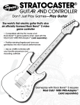
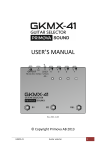
ATG Luthier Installation Manual version 1.2 January 17, 2014 Henrik Bridger (Luthier) Andy Hildebrand (Engineer) Matt Mitchell (Luthier and beta installer) Contents Chapters 1 Introduction ........................................................................................... 2 Guitar Milling and Component Installation .............................................. Materials and Techniques for Installation.................................... Starting Guitar Modification........................................................ Modifying a Strat® or Tele® Style Guitar.................................... Modifying a Les Paul® Style Guitar............................................. Installations Common to All Guitars............................................ 3 Electrical Connections ............................................................................ 4 Non-‐Standard Pickup Spacing Procedure ................................................ 5 String Gain Adjustment Procedure .......................................................... 6 Testing ................................................................................................... 7 Non-‐Standard Installations ..................................................................... Appendices: A Router Templates .................................................................................. B Electrical Connection Details ................................................................. C Tone Control Circuit and Options ........................................................... D DSP Circuit Board Options...................................................................... E End User Warranty................................................................................. 3 5 5 6 6 19 27 34 47 50 51 54 58 62 64 65 66 Installation Requirements The Auto-‐Tune for Guitar Luthier Kit should only be professionally installed. It must be installed by a professional Luthier or technician who is qualified to follow the instructions in this manual. A list of authorized Luthiers can be found on our web site www.autotuneforguitar.com. To become an Auto-Tune for Guitar installer, the following criteria must be met: 1) The installer must install our equipment in cavities milled to the specifications given in Appendix A: Router Templates and interconnect parts as described by the following instructions. 2) Indemnify Antares Audio Technologies and hold us harmless against any losses and damages made to any guitar modified for installation. 2 Chapter 1: Introduction This introduction discusses the standard installation of the ATG (Auto-‐Tune for Guitar) system into an existing guitar. The following diagram is an overview of the features of the ATG: Figure 1.1: Standard ATG Luthier Installation As shown above, the power switch has two positions. In passive position (up position), the guitar's normal pickup audio goes through a Pickup Selector, Tone Control and Volume Control to the quarter inch jack. This passive position does not use or require any power. In the passive position, the guitar is a “normal” old fashioned guitar. Conversely, in the active ATG position, the hex pickup audio goes through the DSP4 board, through the Volume Control then to the quarter inch jack. The DSP4 board knows the position of the Pickup Selector and the Tone Control and digitally simulates their tone. The Tone Control incorporates a push/pull switch. In the pulled-‐out position the power switch is off, for passive guitar operation. In the pushed-‐in position, the power switch is on and ATG is activated. Note that to power the ATG, the user must push-‐in the Tone Pot and also plug a monaural quarter inch plug into the jack. This allows the guitar to be transported without the risk of inadvertently powering on the system. The requirement for the quarter inch mono plug can be defeated as described below, but in that case the user must be prepared to remove at least one battery to assure the unit will not accidently turn on in the case. 3 The Tone Control also incorporates two separate potentiometer sections: One is the normal Tone Pot, the other reports the control's position to the DSP. There is a small circuit board on the Tone Control that allows some optional features which are discussed in Chapter 3: Component Installation and Appendix C: Tone Control Circuit and Options. The Volume Control incorporates a momentary push switch. This is the String Tune button as shown in Fig 1.1. Uses of the String Tune button are numerous, and fully explained in the ATG User's Manual. There are a number of variations of this system, depending on the specific configuration you ordered: -‐ 3 or 5 position Pickup Selector -‐ LP (Les Paul®) or ST (Strat®/Tele®) pickup spacing -‐ 0, 1 or 2 Encoders -‐ knob color (chrome or black) The three and five position Pickup Selectors have multiple poles so that they can operate as normal selectors and also report their position to the DSP board. The DSP board is configured for the selector shipped with your kit. As discussed in Chapter 4: Non-‐Standard Pickup Spacing Procedure, the DSP board is configured for the recommended hex pickup to bridge spacing for either the Les Paul® or Strat®/Tele® (LP or ST) spacing you have chosen. For the correct tone from the DSP, it is beneficial for you to use the spacing you have actually installed. If your spacing is different than the standard, you must follow the procedures outlined in Chapter 4: Non-‐Standard Pickup Spacing Procedure. Finally; the battery holder supplied has room for four AA batteries. Alkaline batteries last about ten hours. Lithium batteries last about twenty hours. You can replace this holder with a 9 volt battery holder, in which case Alkalines last about 2 hours and 40 minutes and Lithiums last about 8 hours and 40 minutes. Cheap batteries can have half the lifetime of good quality batteries. You can also opt for no batteries at all, and instead use an externally connected 5 VDC to 9 VDC external power. You can use both batteries and external power. In that case, if the external voltage is present, the batteries are not used. If the external power is removed, the batteries are automatically (and seamlessly) switched in. This option is discussed in Appendix B: Electrical Connections and Options. Warning The absolute maximum voltage that may be supplied is 10 volts! Higher voltages will damage the DSP circuit board. 4 Chapter 2: Guitar Milling and Component Installation Cautions and Safety Always wear eye, ear (routers are after all almost as loud as your average guitar player), and dust protection when using routers. Be absolutely sure that no loose hanging clothing or long hair can get caught in the spinning router. Seriously, this is something one should avoid… Materials and Techniques for Installation Tools needed: • 2-‐4 Clamps – Jorgensen or similar. • Router – Preferably one that accepts ½” shank router bits. • 1/2” Straight router bit • Guide bushing for router base -‐ 5/8-‐Inch O.D. -‐ 17/32-‐Inch I.D. Recommended: Shop Fox D3117 Brass Guide Bushing Set • Drill – regular or cordless • Awl or similar sharp object (to mark the hole locations) • 5/8” Forstner drill bit (Drilling for the 8 Pin connector) • 1/4” extra long drill bit (Drilling the wire hole from the battery cavity to the circuit board cavity.) • 3/8”-‐1/2” drill bit (Drilling the channel between the circuit board cavity and the control cavity. This may or may not be needed depending how the cavity is routed.) • 1/8” drill bit for use with both wood and metal (Used to drill the hole where the LED is mounted and drilling through a Tele® bridge plate) • 1/16” drill bit (Used to drill the screw holes for the hexaphonic pickup) • 1/4” or 5/16” drill bit for use with both wood and metal (For drilling the hole for the pickup wire) • Hot Glue Gun (for gluing in the LED) • Center Punch (very handy for “punching” a starting point when drilling through metal) • 1/2" (0.5") Flush trim router bit with bearing • Double stick tape (Carpet tape or similar) • Countersink Bit 5 As there are so many different electric guitar types available, each installation will vary greatly depending on what kind of guitar is to be modified. The most common installation of the Auto-‐Tune for Guitar kit will require cavities and recessed areas be routed and several holes drilled. The parts that will need to go into the guitar are the following: • ATG-‐DSP4 circuit board • Hexaphonic pickup • Battery holder (4 AA, supplied or 9V, you supply) • Pickup Selector (replaces the original one in the guitar) • Volume Potentiometer (replaces the original one in the guitar) • Tone Potentiometer (replaces the original one in the guitar) • Zero, one or two Encoders (depending on kit version) • 8-‐Pin MIDI Connector • LED Router Templates: To make covers and rout cavities, there are template drawings included in Appendix A: Router Templates. Easier still, Antares sells router templates. To purchase these templates, please contact us through www.autotuneforguitar.com. Fig 2.1 Antares templates 6 Warning Make sure that the correct router setup is used depending on what template is used. There are two setups: One with a 5/8 router bushing and 1/2 straight or end mill for making holes in wood. The second setup uses no bushing and a flush cut blade for cover plates. (All cover plate templates have screw holes.) The templates for Les Paul® and similar guitars having a Les Paul® shaped control cavity include: • Circuit board cavity, deep battery cavity, and angled 3-‐way Pickup Selector cavity templates for Les Paul® type guitars: This adds another section to a “regular” Les Paul® rear routed cavity where the circuit board is mounted. Also routs the deep part of the battery holder and angled 3-‐way Pickup Selector cavities. • Recessed templates for Les Paul® type cover plate, angled 3-‐Way Pickup Selector cover plate, and recessed area for the battery holder: Use this for routing the recessed lip around circuit board, angled 3-‐Way Pickup Selector, and battery holder. • Les Paul® type cover plate template: Outline of the cover plate, including the screw locations. • 3-‐Way Pickup Selector cover plate template: Outline of the cover plate, including the screw locations. For Strat®, Tele®, and all other guitars, the templates include: • Circuit board cavity template: This template can be used in most guitars for the cavity where the circuit board is mounted. • Recessed cover template for circuit board: Use this for routing the recessed lip around the cavity in order to flush mount the cover plate. • Cover plate template: Outline of the cover plate, including the screw locations. • Battery holder template and insert: Two step routing template that routs both the deep cavity and the recessed area for the battery holder. Making Cavities: When routing ANY of the cavities in the guitar, one MUST use a 5/8 guide bushing attached to the middle of the router base plate and a 1/2" (0.5") straight or end mill router bit. Do NOT use a flush trim router bit or ball bearing bit with any of the cavity templates. Doing this will result in cavities that are too large to fit the covers made with our templates. 7 To minimize scratches, dents, ... and other marks on the finish of the guitar, before clamping any of the templates to a guitar, we recommend placing a layer of Scott® Shop Towel between the finished guitar surface and the routing template. These towels can be purchase from most hardware stores as well as online: http://www.scottbrand.com/products/do-‐it-‐yourself/shop-‐towels Making Covers: Here are some suggestions to materials that we have used for covers with great success: http://www.stewmac.com/shop/Pickguards/Pickguard_materials/Cream_Pickgu ard_Material.html?actn=100101&xst=1&xsr=1048 http://www.stewmac.com/shop/Hardware,_parts/Electric_guitar:_Pickguards/B lack_Pickguard_Material.html http://www.stewmac.com/shop/Pickguards/Pickguard_materials/White_Pickgu ard_Material.html?actn=100101&xst=1&xsr=1048 Fig 2.2 A cover template always has screw holes. Cut the cover material slightly oversized in comparison to the router cover template. Use the double stick tape to attach the material to the cover template (these templates have screw holes). Install flush trim bit in the router (router table recommended) and set the 8 appropriate height in order for the bearing to roll against the template and the cutter against the oversized cover material. Trim the overhang by carefully routing around the template. With the template still attached to the cover, drill the screw holes with a 1/16" (0.0625") drill bit. Remove the cover from the router template. Using a countersink bit, on the "outside" of the cover, drill down enough for the screw heads to fit when attached to guitar. Pay extra attention to which side of the template goes in and which side goes out. Accidentally countersinking the inside rather than the outside is something that has been done more than once… Starting Guitar Modification Start by removing all of the hardware (bridge, pick guards, strap buttons, etc.), electronics, pickup(s), Volume Potentiometer(s), Tone Potentiometer(s), Pickup Selector, switches, output jack, wiring, etc. from the instrument to be modified. On guitars with non-‐removable hardware, for example bridge posts, please take extra caution as to not rout in to these parts during the modification. Spinning router bits and guitar hardware do not go well together. We recommended unbolting and removing the neck from the instrument if this is an option, as this will make it easier to complete the necessary modification to the guitar body. Please note that this may or may not be an option on neck-‐through the body or glue in neck instruments as these necks can be very difficult to reattach. If the guitar that is to be modified has a ground wire running from the existing cavity to, for example, a bridge post on the guitar, try to avoid routing through this area if possible. The router bit will more than likely cut right through the wire without any issues, but re-‐ grounding the cut off wire can pose a potential problem. We at Antares did unfortunately learn this the hard way during the modification of a prototype guitar… Modifying a Strat® or Tele® Style Guitar Circuit board: The ATG-‐DSP4 circuit board is small enough to fit under the pick guard of both Strat®s and Tele®s. In order to be sure that the pick guard covers the cavity to be routed, lay the pick guard in its original position: 9 Fig 2.3 Step 1: Using a low-‐tack tape or similar, place small pieces of tape to outline the shape of the pick guard. This will minimize the risk of routing outside of the area covered by the pick guard. Fig 2.4 Step 2: Carefully place the circuit board cavity template so the template’s rectangle is located between the pickup cavities and the taped outline of the pick guard. Once located, clamp down the template so there is no chance of template movement during the routing. An unsecured router template will most likely deliver less desirable results. 10 Fig 2.5 Step 3: Attach the brass guide (5/8-‐Inch O.D. -‐ 17/32-‐Inch I.D) to the router base and firmly install the ½” router bit in the router’s collet. Fig 2.6 Step 4: In several passes, route the cavity to a total depth of ¾”. Step 5: In order to fit all the wires, it may be necessary to drill a hole from the circuit board cavity to the control cavity. 11 Battery holder: Battery Holder As discussed in Chapter 1: Introduction, the supplied 4 AA battery holder is used to power the Auto-‐Tune for Guitar system as this will provide the longest battery life. Alternatively, a single 9 Volt battery can be used for power. If using a 9 Volt battery, here are the recommended parts: Router template: http://www.stewmac.com/shop/Electronics,_pickups/Battery_clips_and_hol ders/Battery_Box_Template.html Battery box: http://www.stewmac.com/shop/Electronics,_pickups/Battery_clips_and_hol ders/Battery_Box.html?actn=100101&xst=1&xsr=3579 There is no exact location for the battery holder. We suggest placing the battery holder on the lower bout of the guitar body’s back (See picture below). Care must be taken as to not rout into any hardware or other cavities on the front of the guitar. Fig 2.7 Step 1: Place the recess template for the battery holder over the battery holder to align the location where the recess should be routed. Once located, clamp down the template so there is no chance of template movement during the routing. 12 Step 2: Attach the brass guide (5/8-‐Inch O.D. -‐ 17/32-‐Inch I.D) to the router base and firmly install the 1/2” (0.5”) router bit in the router’s collet. Fig 2.8 Step 4: Reset the cutter depth to 1/8” and rout the recess area to this depth. (Note in the above image, we made something that is a bit of a miss. Luckily, Dr. Andy knew immediately the hole was too deep for the flange and stopped…) Step 5: Remove the template from the guitar. Fig 2.9 Step 6: Place the deep rout part of the template for the battery holder and center this over the recessed area. 13 Fig 2.10 Step 7: In several passes, route the inner cavity an additional 7/8" to a total depth of 1” of wood. Step 8: After removing the template, using the 1/4” drill bit, drill the necessary hole(s) for the battery wires to reach the circuit board cavity. One hole might be all that is needed, however, if the wires need to go through the control cavity, two holes might be necessary. Pickup location: Since Strat®s for the most part have bridges with tremolo and Tele®s usually have hard tail bridges, the pickup mounting procedure will differ. Here are the instructions for each modification: For Strat®s and other tremolo/whammy equipped guitars: Fig 2.11 14 Step 1: The hexaphonic pickup needs to be mounted as close to the front of bridge as possible WITHOUT actually touching the bridge plate whether the tremolo/whammy is engaged (moving) or in its regular playing position. The center of the pickup should end up between 3/4 to 7/8” (0.75-‐0.875) from the string break-‐over point on the saddles. Step 2 : Depending on the bridge height and overall action of the guitar, it might be necessary to cut out a small area of the pick guard where the pickup attaches to the body. The final clearance needs to be one sixteenth (1/16”) of an inch (0.0625”) measured from the underside of the strings to the top of the pole pieces. Fig 2.12 Step 3: The wire coming out of the bottom of the hexaphonic pickup is located between the B string and the G string. Step 4: Carefully locate where the pickup is to be mounted. Fig 2.13 15 Step 5: Once in place, mark where the wire comes out of the bottom of the pickup. Fig 2.14 Step 6 : Drill a 1/4” to 5/16” size hole, approximately 1/2” deep, straight down centering the hole in the middle of the pickup area. Fig 2.15 16 Step 7: The hole for the pickup wire may now need to be connected with the control/pickup cavity for the wire to be able to reach the circuit board. Fig 2.16 Step 8: Once the pickup position in located, mark to two holes at each end of the pickup using an awl or similar sharp object. Step 9 : Drill the two pickup mounting holes at a 90-‐degree angle to the strings using a 1/16” drill bit. Careful not to drill too deep! For Tele®s and guitars using a Tele® style bridge where the bridge pickup is mounted in the bridge plate (Ashtray or Modern Style) : Mounting the hexaphonic pickup on ashtray or modern style Tele® bridges requires modification of the bridge plate. If the bridge plate has a faceted edge (Vintage or Ashtray style), it will be necessary to notch out two slots in the facet in order to mount the pickup flat on the bridge plate. It is also necessary to drill three holes through the bridge plate, two for the mounting screws and one for the pickup wire. If the bridge plate is flat (Modern Style), only the holes for mounting screws and pickup wire are required. It is advisable to use a modern style Tele® bridge as this is a lot easier to modify. Here are some recommended replacement bridges: http://www.stewmac.com/shop/Bridges,_tailpieces/Electric_guitar,_non-‐ trem_bridges/Gotoh_Modern_Bridge_for_Tele.html http://www.allparts.com/telecaster-‐bridges http://store.hipshotproducts.com/cart.php?m=product_list&c=38 17 The hexaphonic pickup needs to be mounted 1/2” (0.50) from the string break-‐over point on the saddles. It is possible to mount the pickup farther away provided you are mounting it as close as possible to the break-‐over point. If mounting at spacing different than 1/2", you must disclose this data to the guitar software using Chapter 4: Non-‐Standard Pickup Spacing Procedure. Depending on the bridge height and overall action of the guitar, it might be necessary to shim the neck a small amount in order to get enough space for the pickup between the bridge plate and the bottom of the strings. The final clearance needs to be one sixteenth (1/16”) of an inch (0.0625”) measured from the underside of the strings to the top of the pole pieces. The wire coming out of the bottom of the hexaphonic pickup is located between the B string and the G string. Step 1: Carefully locate where the pickup is to be mounted. Once in place, mark as closely as possible where the wire comes out of the bottom of the pickup. Step 2: Using a center punch, “punch” a mark where the hole is to be drilled centering in the middle of the pickup area. The “punch” will prevent the drill bit from drifting. Step 3 : Drill a 1/4” to 5/16” size hole through the bridge plate, straight down centering the hole in the middle of the pickup area. Step 4 : Place the pickup on the bridge plate and feed the cable through the hole. Step 5: Use the center punch to mark to two locations on the bridge plate for the pickup mounting screws. Step 6: Drill an 1/8” hole at each one of the “punch” marks for the pickup mounting screws. Step 7: Place the bridge plate back in its location on the guitar. Step 8: The area underneath the pickup wire hole may need to be drilled out in order for the pickup wire to first reach the pickup cavity and then the circuit board. Use your imagination along with drill and appropriate drill bit to complete. Step 9: With bridge plate still in place, mark the two holes for the pickup mounting screws. 18 Step 10: Drill the two pickup mounting holes at a 90-‐degree angle using a 1/16” drill bit. Careful not to drill too deep! Modifying a Les Paul® Style Guitar: Circuit board and battery holder: Battery Holder As discussed in Chapter 1: Introduction, the supplied 4 AA battery holder is used to power the Auto-‐Tune for Guitar system as this will provide the longest battery life. Alternatively, a single 9 Volt battery can be used to for power. The ATG-‐DSP4 circuit board cavity is routed as an extension to the already existing electronic cavity in the guitar. There are two router templates, one for the circuit board and battery holder, and one for the three-‐way angled Pickup Selector. When placed correctly on the back of the guitar, both the circuit board and battery holder cavities can be routed without moving the template. Then just flip this template over and line it up to rout the deep cavities. To rout the expansion of the three-‐way angled Pickup Selector cavity, simply use the second template. Rout the recess area and then flip the template over to rout the deep cavity. If using a 9 Volt battery, here are the recommended parts: Router template: http://www.stewmac.com/shop/Electronics,_pickups/Battery_clips_and_holders/ Battery_Box_Template.html Battery box: http://www.stewmac.com/shop/Electronics,_pickups/Battery_clips_and_holders/ Battery_Box.html?actn=100101&xst=1&xsr=3579 19 Step 1: Carefully position the recess template for control cavity and battery holder so that the lower border and right-‐hand corner of the template parallels the outline of the original cavity by a 1/8” (0.125”). Fig 2.17 Step 2: Once located, clamp down the template so there is no chance of template movement during the routing. An unsecured router template will most likely deliver less desirable results. Step 3 : Attach the brass guide (5/8-‐Inch O.D. -‐ 17/32-‐Inch I.D) to the router base and firmly install the 1/2”router bit in the router’s collet. Step 4: Set the router to rout an 1/8” (0.125”) deep recessed area for both control cavity and battery holder. Step 5: Rout both the control cavity and battery holder recess areas. Fig 2.18 20 Step 6: Carefully flip over and align the DSP board/Battery deep rout template 3/16” (0.1875”) inside the edge of the recessed area of the control cavity where the DSP board is to be placed. This will ensure that the deep routed area leaves an even amount of recessed lip around the area. Step 7: Once located, clamp down the template. Fig 2.19 Fig 2.20 Step 8: In several passes, rout the deep cavity to a total depth of 3/4” (0.75”) below the recessed area. This means that you need to add an 1/8” (0.125”) to the total depth from the back of the guitar. An 1/8” (0.125”) for the recess plus 3/4” (0.75”) for the cavity. Step 9: Reset the router depth and in several passes, route the inner section of the battery cavity to a total depth of 7/8” (0.875”) below the recessed area. An 1/8” (0.125”) for the recess plus 7/8” (0.875”) for the cavity. 21 Routing the Pickup Selector: Step 1: Position the 3-‐Way selector template over the original 3-‐way Pickup Selector cavity. The template needs to be aligned so that the left part of the oval shaped hole parallels the outline of the original cavity by a 1/8” (0.125”). The template will only line up on the left side of the original circle and show the new recessed area to be routed on the right side. The template also needs to be aligned at a slight angle in order to not rout over the edge and into the waist of the guitar. Fig 2.21 Step 2: Once located, clamp down the template so there is no chance of template movement during the routing. (For the picture above, double-‐stick tape was used instead of clamps.) Fig 2.22 Step 3: Set the router to rout an 1/8” (0.125”) deep recessed area for the new 3-‐way Pickup Selector cavity 22 Step 4: Rout the recessed area for the 3-‐way Pickup Selector cavity. Step 5 : Flip the template over and align the deep rout for the 3-‐way angled Pickup Selector 3/16” (0.1875”) inside the edge of the recessed area. This will ensure that the deep routed area leaves an even amount of recessed lip around the area. Fig 2.23 Step 6: Reset the router depth and in several passes, route the inner section of the 3-‐way angled Pickup Selector to a depth that just matches the shallowest area of the original round cavity. Please, pay extra attention when routing this deep of a cavity as one under no circumstances wish to rout through the front of the instrument. A mishap on this scale could potentially jeopardize the sustain of both guitar and its owner. 23 Battery connections: Fig 2.24 Step 7 : Using the 1/4” drill bit, drill the necessary hole for the battery wires to reach the circuit board cavity. Drill the hole in the wall between the circuit board cavity and the battery cavity as close as possible to where the battery connector is on the circuit board. We want as little of the battery wire to pass over the circuit board as possible. Pickup location: The hexaphonic pickup needs to be mounted as close as possible to the break-‐over point. Preferably .5 to .8 inches. After installation is complete, you will need to input the spacing data to the guitar software using Chapter 4: Non-‐Standard Pickup Spacing Procedure. Fig 2.25 24 On Les Paul® style guitars, the pickup will be mounted parallel to the Tune-‐o-‐matic style bridge WITHOUT touching any part of the bridge. The wire coming out of the bottom of the hexaphonic pickup is located between the B and G string. Fig 2.26 Step 1: Carefully locate where the pickup is to be mounted. Once in place, using an Awl or similar sharp object, mark where the wire comes out of the bottom of the pickup. Fig 2.27 Step 2 : Centering the hole in the middle of the pickup area, drill a 1/4” to 5/16” size hole at a slight angle so that the hole connects with the bridge pickup cavity. 25 Fig 2.28 Step 3: Place the pickup in its exact location and mark the two holes at each end of the pickup using an awl or similar sharp object. Step 4: Drill the two pickup mounting holes matching the neck angle using a 1/16” drill bit. It is very important to match the angle of these holes to the fingerboard as the top of the pickup should be aligned parallel to the plane of the strings. 26 Installations Common to All Guitars 8-‐Pin MIDI Connector: The MIDI connector is required to allow the user to control ATG settings from a MIDI control device or sequencer. The major selections of Settings, Capo up, Capo down, Alternate tunings, Doublings and Models can be set from the fret board or Encoder Controls. However, many other controls can only be set from MIDI. The MIDI connector is also required to allow the user to download new software, and to allow you, the luthier, to adjust pickup position and string gain. The best location for the 8-‐Pin MIDI Connector is on the side of the guitar close to the output jack. For Strat®s, drilling the hole “in line” with the output jack plate allows easy drilling straight in to the existing cavity: Fig 2.29 For Tele®s, looking at the front of the guitar, anywhere left (right-‐handed guitar) of the output jack works perfectly. This also allows the hole to be drilled into the existing cavity: Fig 2.30 27 For Les Paul® style guitars, the hole is placed similarly as Tele®s: Fig 2.31 Step 1: Using an awl or similar sharp object, mark the location where the hole is to be drilled. Step 2: With a Forstner bit, drill a 5/8” (0.625”) at a 90-‐degree angle into the side of the guitar. Be careful to aim directly for the existing cavity. (Please see pictures above showing both Strat® and Tele®.) Step 3 : Place the 8-‐Pin MIDI Connector in the hole while still warm and mark the locations for the two mounting screws. Fig 2.32 Step 4: Drill two 1/16th (0.0625”) holes for the mounting screws. It is also recommended to counter sink these two holes. This will minimize cracking and chipping off the finish when screwing in the mounting screws. Finish repairs are, for the most part, not enjoyable. 28 Shielding: Once the cavities are routed and all of the holes are drilled for the wires, it is now time to shield/ground the inside of the cavity. There are two ways to shield the instrument and here are some of the common procedures: -‐ Conductive Shielding Paint: This is an easy way to shield the inside of cavities and holes by painting with a small brush. As with all paint, the conductive shielding paint has a tendency to get all over the place, especially on white guitars, so please apply in small doses at a time. Fig 2.36 http://www.stewmac.com/shop/Electronics,_pickups/Supplies:_Shielding/Conductive_ Shielding_Paint.html -‐ Conductive Copper Tape: This method is more time consuming and labor intensive than using the conductive shielding paint, however, it will most likely provide better results. Be careful using this material, as the edges are very sharp and will cut your skin if the opportunity presents itself. http://www.stewmac.com/shop/Electronics,_pickups/Supplies:_Shielding/Conductive_ Copper_Tape.html?actn=100101&xst=1&xsr=0029 29 LED placement: LED and Tone Even though the quest for ultimate tone has long been a wildly discussed topic in the guitar world, we at Antares can guarantee that the LED placement will have very little impact on the tonal response from the Auto-‐Tune for Guitar technology. You must place the LED in a location visible to the player during performance. On Strat® or Tele®, we recommend through the pick guard next to one of the pickups or close to the control knobs. Step 1: Once the desired location for the LED has been determined, drill an 1/8” hole through the pick guard. Step 2: From the inside of the pick guard, place the LED in the hole and using a hot glue gun, attach the LED to the pick guard. On a guitar with pickup rings, consider mounting the LED in the bridge pickup ring facing the player. Step 1: Once the desired location for the LED has been determined, drill an 1/8” hole through the side wall of the pickup ring. Fig 2.33 Step 2: Place the LED in the hole on the inside of the pickup ring. 30 Step 3: With the hot glue gun warm and willing, glue the LED in place from the inside. Fig 2.34 Encoders: If the installation does not include the addition of Encoder(s), this step is probably not necessary to complete. Should the installation call for one or two Encoders, it will however be appropriate to complete the inclusion. For Strat® and Tele® type guitars, it will most likely be necessary to perform some modification to the instrument for the Encoders to fit. The location of the Encoder(s) will have to be determined by the installer and/or instrument owner. Fig 2.35 If only one Encoder is to be used, then simply removing the second Tone Potentiometer on a Strat® pick guard will work perfectly (see above). Should two Encoders be part of 31 the installation, routing a cavity mounting the Encoder either from the front or back is advisable. For guitars with four potentiometer holes (Les Paul®, SG®, etc.), removing one of the Volume and Tone Potentiometers will be an easy solution to fit two Encoders. If only one Encoder is to be used, removing either a Volume or Tone Potentiometer will be the obvious way to go. Keep in mind that the Auto-‐Tune for Guitar technology only uses one Volume and one Tone Potentiometer. Mounting the DSP circuit board: It is absolutely crucial to mount the ATG-‐DSP4 circuit board on a flat surface. By attempting to mount the circuit board on an uneven surface in the guitar cavity, one runs the risk of flexing/bending the circuit board. The flexing/bending can potentially ruin the circuit board, which would be most unfortunate. Make sure that nothing conductive (painted surface or copper tape) can contact the bottom of the circuit board. DSP Board Positioning ATG-‐DSP 4 should be oriented in such way that the pickup wire barely passes over the circuit board. For Les Paul type of guitars, the pickup connector on the circuit board should be oriented towards the neck. For Strat and Tele style guitars where the ATG-‐DSP4 is mounted under the pick guard, orienting the pickup connector on the circuit board towards the neck and running the pickup wire through the “regular” pickup wire channel before entering the DSP cavity is ideal. 32 Carefully place the ATG-‐DSP4 circuit board in the position where it is to be mounted. Using an awl or similar sharp object, mark the location of the four screw holes. Remove the circuit board before drilling the four pilot holes for the screws. For obvious reasons, please be sure to not drill the pilot holes too deep. It is very distressing to realize one has accidentally drilled through either to the front or back of the guitar. Again, we at Antares did unfortunately… Once the pilot holes are drilled, without over-‐tightening, use the four supplied screws to attach the circuit board in the cavity. The ATG label: Fig 2.36 The kit includes two Auto-‐Tune for Guitar labels, one black and one white, that we ask to be put on each guitar that is equipped with the Auto-‐Tune for Guitar technology. We recommend attaching one of the two labels, depending on which will be most visible on the guitar, on the back of the guitar's peg head. 33 Chapter 3: Electrical Connections This chapter provides step-‐by-‐step instructions for connecting all of the components in a standard installation. If there are other active circuits in the guitar, you should read Chapter 6, Non-‐standard Installations before you proceed. At this point, you should have conductive paint installed in the control and DSP4 board cavities and cover plates. (The battery compartment does not need conductive paint.) Encoder(s) and the DSP4 board can be installed at this time, since they are easy to connect in-‐place. Other controls are best connected out of the guitar, and then installed. The Tone Pot is the central point of a star grounding system. There are several options for grounding and Tone Control that are discussed in Appendix C: Tone Control Circuit and Options. Ground connections we do not anticipate here should be connected to the Tone Pot to avoid ground loops. Grounds are actually circuits with their own currents, radiation and noise issues. If you are not sure something is grounded, test it first, before soldering to the Tone Pot. Careful treatment of grounding is implicit in this design. Many cable lengths do not matter and excess wires can be coiled up, because they are low current and/or have few signal transitions and are not a source or subject of digital noise. Certain other cable lengths should be kept to a minimum, and these will be obvious (e.g. shielded audio cabling) or will be discussed explicitly. A final consideration is the orientation of the DSP4 (main circuit board) and the cables that are involved in connecting it. The left side of the DSP4 (as pictured below) contains the sensitive analog circuitry and is susceptible to EMI (electro-‐magnetic interference). Cables should be kept away from that area when possible. The right side of the DSP4 contains power supply circuitry and can be a source of noise. Cables should be kept away from that area lest they pick up EMI. The DSP4 board should be oriented to minimize the board overlay of the hex pickup cable and the board overlay of the battery cable. The pickup is susceptible to interference and the battery cable has a fair amount of radiation from current flux from digital switching. Concerning soldering: when a bare wire is soldered to a lug, it is susceptible to breaking if it is bent at the joint. A length of heat shrink tubing is provided so you can reduce breakage by covering joints. The following Figures are referred to in the installation text below: 34 Fig 3.2 -‐ Tone Pot circuit board Fig 3.3 -‐ Encoder circuit board Fig 3.1 -‐ DSP4 circuit board 35 Finding pin 1: In the instructions that follow, you will need to identify pin 1 of the connector housings. First, find the cable that looks like: Fig 3.4 -‐ DSP4 to DIN cable This is the MIDI to DIN connector cable. Pin 1 is the brown wire at the bottom. Look at the top of the housing (where the wires enter). You will see a small notch in the side of the plastic flange at pin 1. This is how you identify pin 1 of the connector housing. You will also notice notches in the housing at pins 5 and 10, when present. Step by Step Instructions: Step 1 -‐ grounding System: Verify that the installed Tone Pot will be mounted onto conductive shielding paint. If it is not, either add paint so it is, or connect with a jumper wire (not provided) between the Tone Pot chassis and the conductive paint. Step 2: Active Hex Pickup cable: Install the pickup cable by running it into the DSP cavity. Reduce the cable length if necessary and possibly change the circuit board orientation (see B below). Then insert the wire pins into the 13-‐ pin plug as shown in Fig 3.5. Install the 13-‐pin plug into the circuit board "hex pickup header" shown in Fig 3.1. There are considerations with the hex pickup wires and circuit board orientation: A) Avoid running the pickup cable under or over the circuit board. 36 B) Minimize the length of the pickup cable. Keep excess wiring away from the circuit board. Alternatively, cut wiring lengths away and re-‐ solder wires together. Note: The Braid has black insulation and is covered with red shrink-‐wrap tubing. It is thicker than the other wires. Fig 3.5 -‐ Hex Pickup wiring -‐ note Housing pin numbers are 1, 3, 5, .... Step 3: Encoder assemblies: 1) If you have a no Encoders, go to the next step. 2) If you have one Encoder, install the "Fig 3.7 -‐ Encoder shorting header" into the "6 position Encoder" header on the DSP4. Install the "Fig 3.6 Encoder jumper cable" between the 13 position Encoder circuit board and the DSP4, where indicated. Note: the Encoders are marked with a line on the body near position 6 or 13. 3) If you have two Encoders, install the "Fig 3.6 Encoder jumper cable" from each Encoder to the circuit board as indicated on Fig 3.1. 37 Fig 3.6 -‐ Encoder jumper cable Fig 3.7 -‐ Encoder shorting header Fig 3.8 -‐ LED assembly Step 4: LED: The LED is used to show power ON and flashes on a successful "string tune". It is required that the LED be visible to the artist during performance. Very often, we have installed the LED into a pickup ring. In one case with a tan colored ring, we drilled into the inside of the ring, but not through it, and mounted the LED with a glue gun. There was no indication of the LED until the unit was powered on, in which case you could clearly see it. It is not necessary to shorten the LED cable, unless you are compulsive, in which case we would not want to deprive you of true satisfaction (we are compulsive too). Install the LED assembly plug (Fig 3.8) into the LED header of the DSP4 circuit board. Step 5: Passive pickups to Pickup Selectors: Note: On Les Paul® installations, postpone this step until after steps 6 and 7, since the pickups need to be mounted before soldering them to the selector, but this makes it impossible to feed the cables from the selector through the pickup cavities to the DSP4 board and Tone Pot. An augmented procedure 38 for Les Paul® installs would be to combine parts of Steps 5, 6 and 7 as follows: For Les Paul®: Solder the “Pickup Selector pigtail” and “Selector to Tone Pot cable” to the Pickup Selector. Solder jumpers between lugs on the Pickup Selector as shown in Fig 3.9. Feed cables through cavities and connect to the DSP4 and Tone Pot. Install the passive pickups and solder their cables to the Pickup Selector as shown in Fig 3.9. The three position Pickup Selectors: Solder the Passive pickups Neck and Bridge to the selectors as shown in Fig. 3.10 or 3.11. Solder the Passive Pickup Ground to the selector as shown. Fig 3.9 -‐ Les Paul® three position pickup assembly 39 Fig 3.10 -‐ Tele® three position pickup assembly Fig 3.11 -‐ Five position pickup assembly Step 6: Pickup Selector to DSP4 circuit board: Identify the 3 or 5 position Pickup Selector pigtails shown in Fig. 3.12 and 3.13, respectively. Note, they both have a five-‐pin plug. Cut the wires to the correct length and solder them to the Pickup Selectors as shown in Fig. 3.9, 3.10 or 3.11, respectively. (NOTE, THE SELECTOR FIGURES ARE DRAWN WITH THE PINOUT IN THE OPPOSITE ORIENTATION THAN THE PIGTAIL FIGURES. FOLLOW THE PIN NUMBERS. 40 Install the selector plug into the Pickup Selector header of the DSP4 circuit board. Fig. 3.12 -‐ 3 position Pickup Selector pigtail Fig 3.13 -‐ 5 position Pickup Selector pigtail Step 7: Pickup Selector to Tone Pot assembly: Identify the Selector to Tone Pot cable as shown in Fig. 3.14. This plug is connected to a shielded cable. This is the shielded cable shown in Fig 3.9, 3.10 and 3.11. Cut the cable to the correct length and solder to the Pickup Selector as shown. Note that two solder connections are required; the signal wire and the shield. The shield must be soldered to the "Passive Pickup Ground". It is this shield connection that connects the Passive Pickup Ground to the central Tone Pot ground. Install the Selector to Tone Pot plug (Fig 3.14) into the "Pickup Selector passive output" two position header on the Tone Pot circuit board (Fig. 3.2). Fig 3.14 -‐ Selector to Tone Pot cable Step 8: Tone Pot PCB to DSP circuit board: Install the Tone Pot to DSP4 jumper shown in Fig 3.15. Plug one end into the Tone Pot circuit board, (Fig 3.2) and the other into the "Tone Pot" connector on the DSP4 circuit board. 41 Fig 3.15 -‐ Tone Pot to DSP4 Step 9: Battery cable to DSP circuit board: Remove at least one battery from the battery case before installing this cable. Route the battery cable (Fig 3.16) so as to avoid proximity to the analog area of the DSP circuit board or any of the pickup and audio wiring. Shorten the cable to sufficient length to allow installation and maintenance; avoid any excess length. Solder the battery connection cable to the battery compartment. Black to the negative terminal and red to the positive terminal (but we know you knew that!) Plug the cable into the DSP board. Note that there are two different two pin connectors on the DSP board—be sure to use the connector labeled “Bat”. Mount the battery compartment into the battery cavity with the included screws. Fig. 3.16 -‐ Battery cable Step 10: Volume Pot to DSP4 ST (String Tune) input: Using the string tune cable shown in Fig 3.17, solder to the Volume Pot as shown in Fig 3.19, and install the plug into the DSP4 board. Note that there are two different two pin connectors on the DSP board. Be sure to use the one labeled “ST”. Fig 3.17 -‐ String tune cable 42 Step 11: Tone Pot to Volume Pot cable: Identify the cable shown in Fig 3.18. This cable plugs into the Tone Pot circuit board; the shielded wire connects to the Volume Pot and the orange wire connects to the 1/4 inch jack as shown in Fig 3.19. 1) Shorten and solder the shielded wire to the Volume Pot. Note that two solder connections are required; the signal wire and the shield. Keep the excess shielded wire for the next step. 2) Solder the pin 3 orange wire to the TRS jack ring terminal. That configuration requires a mono 1/4 inch cable to be plugged in to power on the DSP4. If that feature is not desired, remove or cut the orange wire and install a jumper at JP1 on the Tone Pot. See Appendix C: Tone Control Circuit and Options, for more detail. 3) Install the plug into to the Tone Pot circuit board shown in Fig 3.2. Fig 3.18 -‐ Tone Pot plug Fig 3.19-‐ Diagram of Volume Pot and TRS connector 43 Step 12: Volume Pot to 1/4 jack cable: Using the leftover shielded cable, connect the Volume Pot output to the Stereo Jack as shown in Fig 3.19. Step 13: Locate the cable pictured in Fig 3.20, and cut to length from the DSP4 to the 8 pin DIN. Solder the cable wires to the plug using the connections given in Fig 3.21. Note that this is a view of the lug (terminal) side of the plug. Install the plug, and install the connector into the DSP4 "8 pin DIN MIDI/pwr" header (See Fig. 3.1). On the Peavey AT-‐200 guitar, the DIN pin 8 is connected to the guitar's audio out. Since that design, it has been found that with typical external cables the MIDI lines couple to the audio line. Even short MIDI control messages cause nasty sounds in the audio. Consequently, in this design, the audio is not connected to pin 8. An 8 pin DIN jack (as opposed to a 7 pin jack) is supplied to allow you to connect either a 7-‐pin or 8-‐pin external cable. Fig 3.20 -‐ DSP4 to 8 pin din cable 44 Fig 3.21 -‐ DSP4 to 8-‐pin din connections (lug view) You will notice that pins 6 and 7 allow a 9-‐volt external power supply. If this voltage is supplied, the internal batteries are not drained. Another option is to provide no internal batteries at all and use only an external 9V DC power source. Note that many 9V DC supplies have significant output noise; harmonics of 60 Hertz or other frequencies, which can cause audio problems. If you use external 9V DC, the best source is batteries. Also, the actual voltage range is 5 VDC to 9 VDC, which will allow you to build a four battery supply pack (4 size C batteries would last at least 32 hours). Be warned that a long, thin, cable will drop the voltage at the guitar. Warning: The absolute maximum voltage that may be supplied is 10 volts! Higher voltages will damage the DSP board. 45 Step 14: Miscellaneous: Attach jack to jack plate, screw in jack plate and 8-‐pin DIN plate, install Volume and Tone Pot if not done already, replace cavity covers. Replace bridge, tailpiece, and any other necessary hardware that has been removed. Install knobs, using shaft adapters for the Encoders. Install the 1/8” to 1/4” shaft adapters for the Encoders: they must be oriented correctly in the knob in order not to block the set screw, and are very difficult to remove if installed incorrectly. Also note that they must be fully seated in the knob in order not to block the set screw, and this requires a little elbow grease or possibly a hammer. (Ed: use the hammer on the knob before it is put on the Encoder.) Set Pickup height (1/16” from strings) and place support foam underneath or use springs as needed. 46 Chapter 4: Non-‐standard Pickup Spacing Procedure The guitar must know the position of the magnetic hex pickup used by the ATG. In the luthier kit, standard positions are expected as follows: Strat®/Tele® Les Paul® kit kit E3 (high E string) .50 .70 B2 .50 .76 G2 .50 .81 D2 .50 .76 A1 .50 .82 E1 (low E string) .50 .88 Fig. 4.1 Bridge turnover to Pickup center in inches. Scale length of 25.5 assumed. For other scale lengths, spacing varies proportionally. If your positions are different by more than 10% from these, then the tone quality will be adversely affected. First, if the 10% tolerance is exceeded, you will need to audition the models. If you think they may be not right, then we have a procedure for you to make them correct. The steps of this procedure are: 1) Create an account. 2) Request Luthier Status from Antares. 3) After the Luthier status is granted, connect the guitar. 4) Log into the Guitar Manager. More detail on these steps follow: 1) Create an account. An easy step: Go to http://www.autotuneforguitar.com. Select the top tab GUITAR CONNECT -‐> CREATE ACCOUNT. 2) Request Luthier Status. Another easy step: Email us at mailto:[email protected] with a request for Luthier status along with the email address you used in creating the account. We will modify your account. 47 3) After the Luthier status is granted, connect the guitar. We will email you back that we have promoted you to the lofty status of "Luthier". To connect the guitar: we maintain the most up to date information about connecting the guitar on the web. First, go to http://www.autotuneforguitar.com. Select the top tab SUPPORT -‐> DOCUMENTATION. Scroll down to "Approved Interfaces and Software" to find out how to purchase a MIDI interface and Y-‐cable. Next, on the documentation page, find "Guitar Connect" for detailed instructions about how to connect your equipment and how connect to the Guitar Manager. The physical interface to MIDI on the guitar is the 8-‐pin DIN plug on the side of the guitar. Fig 4.2: The 8 pin DIN plug on the AT-‐200 and a 5 pin DIN connector The ATG uses both MIDI output and input to connect to the Guitar Manager on www.autotuneforguitar.com so that you can download and manage the guitar's contents. In order to do this you must either connect: A special MIDI "Y" cable. One end of the Y cable connects to the guitar, and the other end has two MIDI 5-‐pin DIN connectors, one for MIDI IN and one for MIDI OUT to connect to a MIDI interface. 48 The Peavey AT-‐200B connection box, which also supports exernal power in. It has MIDI IN and OUT ports that let you connect to a MIDI interface. 4) Log into the Guitar Manager. When you go to GUITAR CONNECT -‐> LOGIN, because of your Luthier status, you will see a button labeled "Pickup Spacing " in the Guitar Manager page. Pressing this button will take you to the "Pickup Spacing " page, which will allow you to enter the correct pickup position data and store that information in the guitar. 49 Chapter 5: String Gain Adjustment Procedure String gain adjustments allow you the set the loudness of each string within a range of -‐6dB to +6dB. This is to compensate for variations of pickup sensitivity and irregular spacing between magnetic pickups and strings. This feature is available for magnetic or piezo pickups using Essential Pack, Pro Pack and Complete Packs. At this writing, the software version installed on the luthier printed circuit board is Complete Pack v2.27, which does not support string gain adjustment. In order to activate string gain adjustment you must download and install Complete Pack v2.28. This more recent version is a free download to owners of Complete Pack v2.27. Both updating to v2.28 and accessing the string gain adjustments are done through our web interface: http://www.autotuneforguitar.com. If you do not have an account, you may create one by selecting the top tab GUITAR CONNECT -‐> CREATE ACCOUNT. Once you have an account, connect you guitar: On the documentation page, find "Guitar Connect" for detailed instructions about how to connect your equipment and how to connect to the Guitar Manager. Once in the Guitar Manager, you will see v2.28 or later. Download that application into your guitar. Start that application: go to SUPPORT -‐> DOCUMENTATION and follow the instructions in "Managing Your Guitar's Software with the Guitar Manager". See "Selecting Installed Feature Packs" to select the v2.28 for execution. Now, go into the Guitar Manager and select the "String Gains" button. You will now be able to enter gains. After you press the "Set Gains" button your guitar will be ready for you to play, so you can hear the new gains. If you do not hear the gain change, it is likely you have not correctly selected the v2.28 for execution and you need re-‐do that process. Once the gains are installed on the guitar, using v2.28 or later will access and apply those gains. 50 Chapter 6: Testing "The following tests I can perform in ten seconds on a two Encoder system. But that's after having done 500 of them" -‐ Andy. Before you proceed, study all the headers. The plugs need to be fully installed in the headers and the pins all need to be fully inserted into their plugs. Push any out of place plugs into place. If any pins are a problem, pull that plug and study the pin and the plug. You will see a tab on the pin, and a flexible plastic tab in the plug. When the pin is correctly inserted, these tabs interlock so the pin cannot come out. Since the pin did come out, there is one of two issues: 1) The pin was not fully installed and the tabs did not interlock. 2) The plastic tab in the header is bend back and not engaging. In that case, push the tab into the body if the plug, and it will function correctly. The testing steps: Step 1: Put batteries in. Step 2: Plug in 1/4 inch jack -‐ it won't turn on without one. Plug the other end into an operating amplifier. Step 3: With the ATG off (Tone Pot pulled out) you should hear the passive pickups, the Tone, Volume and Pickup Selector should work normally. These are the passive circuits. Correct any issues. Step 4: Turn ATG on (press the Tone Control in -‐ if you do this too slow, it will pop). You will see the LED come on. If it does not, do you hear the strings? If yes, it's an LED issue. If no, there a wiring issue in the Tone Control connection or the battery connection. Assuming you hear the strings: the Volume, Tone and Pickup Selector should work normally unless you are dialed into a guitar model that has only has one pickup, or three pickups in the case of a Strat® selector. Step 5: Pickup function: Pluck each string separately. You should hear each clearly. If there is an issue, look at the pickup header to make sure every pin is correctly seated. You may also need to adjust the heights of the pickups for equal loudness. Step 6: String tune function: First: detune each string by about a step sharp or flat. Strum all 6 strings then hold down the Volume Control for no less than 1/10 second -‐ half a second would be fine. Upon release, you should hear a scooping sound and all six strings should be in tune over the amplifier -‐ the strings tensions are not changed. If you did not hear a scooping sound, all six strings were not detected. Did some of the strings change 51 pitch? If no, there is a problem with the string tune button or wiring. If yes, repeat the test. If the scooping sound does not happen but some of the strings are in tune, go back to Step 5. Step 7: Test two Encoder system: Step 7.1: Turn both Encoders fully counter clockwise (CCW). Step 7.2: Strum the strings and turn the Data Encoder (13 position Encoder), clockwise (CW), one step at a time. You should hear the guitar step through the various guitar models. Step 7.3: Turn the Function Encoder one step CW. Now as you step through the Data Encoder, you will hear the different alternate tunings. Step 7.3: Turn the Function Encoder one step CW. Now as you step through the Data Encoder, you will hear the different doublings: twelve string, octaver down, Fifth up, etc. Step 7.4: Turn the Function Encoder one step CW. Now as you step through the Data Encoder, you will hear the Capo Up functions. Start with the Data Encoder fully CCW. Then step CW one at a time. The capo pitch should rise by 1/2 step on every click. At the last position it should be a full octave up. Step 7.5: Turn the Function Encoder one step CW. Now as you step through the Data Encoder, you will hear the Capo Down functions. Start with the Data Encoder fully CCW. Then step CW one at a time. The capo pitch should descend by 1/2 step on every click. At the last position it should be a full octave down. Step 7.6: With the guitar an octave down, turn the Function Encoder one step CW. This is the preset position. One click on the Data Encoders will call up the respective preset. Since the presets are not yet programmed, the parameters will change to the original defaults. Errors with Encoders could be: A) They are plugged into the wrong headers on the circuit board so the function controls data and vice versa. B) The ground is disconnected so they don't work at all. C) One or more of the data lines is disconnected. This will cause other than 1/2 step intervals in going up or down in capo settings. A final note about the Encoder Controls: when you first power on, the Encoder positions are read and that setting is implemented. For example, if the Encoders have the capo up 7 steps dialed in, then you will hear the guitar capo'd up a perfect fifth when you power on. 52 Step 7: Test one Encoder system: Testing a one-‐Encoder system is actually more difficult, but you need to do it to check for incorrect installation of the termination header for the Function Encoder. In a one-‐Encoder system, the Encoder is a thirteen-‐position Data Encoder and it is set by the termination header to recall presets. This means you will need to learn the Fret Control system to set parameters and save presets. Once the presets are saved, you will test that they are recalled correctly. Once you have mastered this system, it only takes a few minutes to test. Testing with a Guitar Tuner After you successfully do a string tune function, your strings will be in tune as heard through the amplifier. Fingered notes on frets will also be in tune up and down the fret board, provided you have not bent the note enough to fall outside the solid-‐tune range. If you attach a guitar tuner to the processed output, you will see the guitar is always in tune. At this point, you may come up against some limitations of your guitar tuner: True stroboscopic tuners need regular maintenance adjustments to control the rate of the rotating wheel(s). Electronic tuners are limited by the accuracy of the crystal oscillator and the quality of the software. Most electronic tuners' accuracy is in the range of +/-‐ 1. to 3. cents. The ATG system has similar limitations. The crystal used has a precision of +/-‐ 20 ppm (parts per million). The oscillator circuit contributes error for a total of -‐20 to +170 ppm, which gives an error of about 0.3 cents, worst case. The pitch tracking software in ATG is extremely precise, adding negligible error. So if your tuner shows the pitch is just a little off, its likely the accuracy of the tuner, not ATG. 53 Chapter 7: Non-‐standard Installations Installing ATG in a non-‐standard manner is usually workable. In some cases you will need to get us involved. That said, we will need to charge you if we put in significant time, or if we need to supply specifically modified equipment. Non-‐standard installations usually involve guitars with other active circuits. Three possible issues are Grounding, Power connections, and On-‐Off control. Grounding If conductors that are supposed to be at the ground reference voltage form loops through which current can flow, bad things may happen. Any time-‐varying magnetic field will induce current flow in these loops. Because the interconnections are less than perfect, these current flows cause voltage drops at the junctions, resulting in multiple ground voltages. This causes hum or buzz in the audio. The basic ATG installation will have no ground loops. But adding other active circuits can cause problems. To solve these problems you will need to disconnect ground connections and determine, with power off using an ohm-‐meter, whether other elements are still connected to ground. Jumper JP3 on the Tone Control circuit board has been provided to help with this exercise. See Fig. C.1 -‐ Tone Pot circuit board. Power Connections Some active circuits, including the ATG, connect the negative terminal of the battery to ground. Circuits that do this can share a single battery, with the obvious consequence of reduced battery life. Other circuits, like the RMC Polydrive® discussed below, "float" the battery defining ground as the voltage midway between the battery terminals. Any attempt to share this battery with a negative terminal grounded system will fail, create a safety hazard and potentially destroy circuits. You must check for this condition before you make any battery sharing connections. On-‐Off Control A feature implemented by several products is to use a TRS stereo jack requiring a monaural 1/4 inch plug to be used for the circuits to be turned on. The default ATG installation also has this feature, because pushing the Tone Pot for power-‐on can happen 54 in guitar cases. Problems show up because there is more than one way to use the TRS jack. Some negative terminal grounded systems run the negative terminal directly to the TRS ring. When the monaural plug is installed the negative terminal is connected to ground and the circuits operate. This approach passes the system battery return current through the inserted plug. This can unexpectedly disrupt amplifier systems and damage speakers, to say nothing about deafness, adrenaline rush and blood pressure spikes. The ATG equipment implements a similar strategy, but uses a "soft" power-‐on control. The circuit board lightly pulls up a wire to 5 volts, which must be grounded for power on, and the grounding circuit is the TRS ring connection to ground. The grace of this approach is that only current limited voltages temporarily connect to the TRS tip pin when the quarter inch plug is inserted, reducing the "pop" to less than a seismic event. Confusion reigns when ATG shares a battery with a TRS ring negative terminal return approach. In this case, you should join the club by permanently grounding the "soft" power-‐on control wire (install JP1 on the Tone Control circuit board; see Appendix C: Tone Control Circuit and Options) and also run the battery pin 2 input from the Sleeve connection of the TRS jack. Example Installation: To give you more ideas about a more complex non-‐standard installation, we will discuss a recent guitar we outfitted. You might read this for amusement, but it may also give you a deeper understanding of how the ATG circuits are designed. Parker Fly® with RMC Polydrive® 1 with 13-‐Pin Output: For an alternate installation example, Fig 7.1 shows a partial view of a RMC Polydrive® 1 system installed on a Parker Fly®. This system was somewhat more complicated than shown because it also included a Sustainiac®. Fig 7.1 is presented to describe the system before the addition of ATG. Fig 7.2 shows the system with the ATG installed (see red). In many ways, this system mimics features in the GK-‐3 system. It provided a low impedance output of all six hex piezos and includes a blend knob that allows mixing of a monaural piezo sound with passive audio. This blending is done with a potentiometer. Because of a lack of inductance on the piezo side, the piezo part of the sound is not modified by the Tone Control. The Volume Control output is shown going through the 13 pin connect because it appears in the “mono output”, pin 7 of the 13 pin connector. This output then goes to the TRS jack. The Polydrive® is an active circuit and is powered by a 9V battery in the guitar when the TRS is plugged in. If power is supplied through the 13 pin connector, the battery is not used and the TRS plug is not needed. The Polydrive® battery negative IS NOT TIED TO GROUND, but floats at -‐4.5V. Therefore, it cannot be shared by the ATG system, which requires a true ground and +6V to +9V DC. 55 Fig 7.1 -‐ System with RMC Polydrive® This is not the only way to do this installation. The decisions were in part guided by the artist, who likes the most flexibility to produce sound, even at the cost of increased complexity. To help explain, Fig 7.2 shows elements changed with ATG in red. The basic idea is to break into the sound path before the piezo sound that goes into the blend knob. You can see this between the two blocks “Polydrive® circuits” and “Blend knob”, which had previously been connected. Now, when the ATG power button is off (up), the Blend knob receives the monaural piezo sound it had received prior to the installation. When the ATG power is on (down), the Blend knob receives the ATG output. The ATG input is six wires directly from the 13-‐pin plug output. This required a special modification to the DSP board to allow unity gain line level input. The 3-‐position lever Pickup Selector was replaced by a 5-‐position selector to let the computer access the Strat® model. It was wired for the 3-‐position case using our 3 to 5 standard: N, N+B, N+B, N+B, B. The Tone knob was a two pot push/pull assembly used by RMC, so there was no way for us to include ATG Tone Pot functionality. We hardwired our Tone Control to full on by connecting pins 1 and 2 in header P8 (see notes below). Because there was no Tone switch for power, a separate power switch (with LED) was wired to the back cover. The battery turned out to be sharable with the Sustainiac® with no ill effects except for reduced battery life. If power is provided through the 8-‐pin DIN, the Sustainiac® battery is not used. If DIN-‐8, 9V DC power is used, the artist was advised to use an outboard 9V battery source because outboard 115 AC to 9V DC converters can 56 cause hum. Not the usual studio hum fixable by enough ground lifts, but hum based on FCC EMI requirements to connect DC system ground to AC grounds through a cap. When using the system, if the artist wants perfect intonation or does any capo or alternate tunings, he will likely turn the blend pot to 100% ATG. If his strings are approximately in tune and he is using standard tuning, he may choose to blend in some of the passive audio for a chorus effect. What is perhaps more interesting is that this is a fretless guitar. When we played it, the ATG brought the imperfectly fingered chords into perfect tune. Using the tremolo or slide gave similar astounding results. Fig 7.2 -‐ Poly drive system with ATG (red). 57 Appendix A Router Templates Outside: 5/8 bushing router guide for 1/8 deep flange. Inside: 5/8 bushing router guide for cavity. 5 inch line to check scale. This appendix presents a number of routing templates. See Chapter 2 for detailed direction on how to use these templates on specific guitars. These images are at a small scale and this Word document will not correctly scale them on printing. However, the documentation CD has full sized PDF files of the images. When you print or copy the CD images, be sure to set the size to 100%, rather than "Fit to Page". Also, some printers and copiers do not exactly print the precisely correct size, so check lengths of the 5 inch calibrated lines. To be totally safe, test out your new templates using some scrap wood to make sure everything is correct. Alternatively, Antares offers affordable acrylic templates which can be purchased through our web site. 5 inch line to check scale. Figure A.1 Les Paul® battery Figures A.1 and A.2 are one template that can be joined at the hash marks. Together, these provide a template to expand the main cavity and add the battery compartment. The battery flange must be 58 milled 1/8 inch deep and the battery cavity must be milled an additional 7/8 inch. In Figure A.2, the cavity referenced is for the printed circuit boar [Matt -‐ The Printed Circuit Boar, prized by poachers for its intricate silicon tusks, has unfortunately been hunted to extinction], and should be routed to a depth of 3/4 inch below the cover flange. 5 inch line to check scale. Outside: 5/8 bushing router guide for 1/8 deep flange. Middle: flush cut guide for cover plate. Inside: 5/8 bushing router guide for cavity. 5 inch line to check scale. Figure A.2 -‐ Les Paul® DSP cavity adjoining control cavity. 59 5 inch line to check scale. Outside: 5/8 bushing router guide for 1/8 deep flange. Middle: flush cut guide for cover plate. Inside: 5/8 bushing router guide for cavity. 5 inch line to check scale. Figure A.3 -‐ Les Paul® selector expansion cavity. Figure A.3 are templates to expand the size of the Pickup Selector cavity. The depth of this cavity should be the same as the existing cavity. 60 5 inch line to check scale. Outside: 5/8 bushing router guide for 1/8 deep flange. Middle: flush cut guide for cover plate. Inside: 5/8 bushing router guide for cavity. Outside: 5/8 bushing router guide for 1/8 deep flange. Inside: 5/8 bushing router guide for cavity. 5 inch line to check scale. Figure A.4 -‐ General template of battery and DSP board cavities. Figure A.4 are templates for non-‐Les Paul® guitars. The upper cavity is for the DSP board and needs 3/4 inch free space. When mounted under a pick guard, the bushing and cover plate are not needed. The battery flange must be milled 1/8 inch deep and the battery cavity must be milled an additional 7/8 inch. 61 Appendix B Electrical Connection Detail The following point-‐to-‐point electrical connections may be helpful to explain options and to diagnose issues such as broken wires or interconnect errors. Encoder circuits: These diagrams can help you diagnose Encoder issues. If pins 1, 2, 4 or 8 break, the Encoders will miss some options. If pin C breaks, the Encoders will not function at all. Fig B.1 -‐ Encoder circuits Tone and Volume Pot connections: Figure B.2 shows the connections between headers, Tone and Volume Pots and TRS connector. These diagrams are useful to track down broken connections or incorrectly wired installations using an ohmmeter. Note that the annotation about grounding the TRS ring wire is outdated by the JP1 feature on the Tone Control circuit board. See Appendix C: Tone Control Circuit and Options. 62 Fig B.2 -‐ Tone and Volume Pot connections 63 Appendix C Tone Control Circuit and Options The circuit diagram, below, helps to describe some of the options you have with the Tone Pot circuit board. There are two pots in the Tone Pot device. One is the usual Tone Pot shown near the bottom of the diagram. A 47nF capacitor is mounted in the circuit board and can be replaced if you choose. The second pot shown at the top of the diagram tells the DSP4 the position of the pot, so that tone can be manipulated by the DSP4. If you want a completely different circuit for your Tone Pot, you can remove jumper JP2 and connect the new circuit to pin 2. Another feature of this assembly is the dual push/pull switch that turns on the DSP4 power and routes either the DSP4 audio, or the passive audio, to the audio out. The Tone Pot body is connected to ground using jumper JP3. If you want to disconnect this ground (typically because it forms a ground loop with other circuits in the guitar) then JP3 can be removed. As discussed above, pin 3 of the P3 header is intended to connect to the ring tab on the 1/4 inch TRS stereo jack. With a mono plug inserted, this circuit is connected to ground and allows the DSP4 power to come on. This is a desirable feature, otherwise the Tone switch could be pressed-‐in by the guitar case causing the unit to turn on and drain the batteries. However, you can defeat this circuit by disconnecting the pin 3 wire and shorting jumper JP1. 64 Fig. C.1 -‐ Tone Pot circuit board 65 Appendix D DSP Circuit Board Options There are two differences between various circuit board configurations. The first is the spacing from the turnover point on the bridge to the center of the hex pickup. This distance must be known to the software and can be input by you using Chapter 4 Non-‐Standard Pickup Spacing Procedure. The second difference is a small toggle switch on the left side of the board. This toggle switch tells the software if a 3 position pickup selector is being used (first -‐ leftmost -‐ toggle up), or a 5 position pickup selector is being used (second toggle up). If you're trying to use a six position selector, you're out of luck. 66 Appendix E End User Warranty To validate the warranty for Auto-Tune for Guitar technology the end user must register and create a Guitar Connect account within 30 days of the installation of the Auto-Tune for Guitar Luthier kit at www.autotuneforguitar.com, Guitar Connect -> Create Account. The Auto-Tune for Guitar hardware and software is warranted against manufacturing defects in material and workmanship for one (1) year. While under warranty, all replacement parts and an installation allowance will be provided without charge. All defective parts must be returned to Antares Audio Technology, 231 Technology Circle, Scotts Valley, CA 95066 for evaluation. 67