1
VERSAFLOW SONIC 2000 / TWS 2000
Portable ultrasonic clamp-on flowmeter
Electronic Revision:
ER 1.0.1
(SW.REV 01.01.01_)
Handbook
VERSAFLOW SON
: IMPRINT ::::::::::::::::::::::::::::::::::::::::::
Notices and Trademarks
Copyright 2013 by Honeywell
WARRANTY/REMEDY
Honeywell warrants goods of its manufacture as being free of defective materials and faulty
workmanship. Contact your local sales office for warranty information. If warranted goods are
returned to Honeywell during the period of coverage, Honeywell will repair or replace without
charge those items it finds defective. The foregoing is Buyer's sole remedy and is in lieu of all
other warranties, expressed or implied, including those of merchantability and fitness for a
particular purpose. Specifications may change without notice. The information we supply is
believed to be accurate and reliable as of this printing. However, we assume no responsibility for
its use.
While we provide application assistance personally, through our literature and the Honeywell
web site, it is up to the customer to determine the suitability of the product in the application.
Honeywell Field Solutions
512 Virginia Drive
Fort Washington, PA 19034
2
www.honeywell.com/ps
34-VF-25-47 iss. 3 GLO Jan 13 US
ABOUT THIS DOCUMENT
VERSAFLOW SONIC 2000 / TWS 2000
Abstract
This document provides descriptions and procedures for the Installation, Configuration,
Operation, and Troubleshooting of your device.
Contacts
World Wide Web:
The following lists Honeywell’s World Wide Web sites that will be of interest to our
customers.
Honeywell Organization
WWW Address (URL)
Corporate
http://www.honeywell.com
Field Solutions
http://www.honeywell.com/ps
Technical tips
http://content.honeywell.com/ipc/faq
Telephone:
Contact us by telephone at the numbers listed below.
Organization
United States and
Canada
34-VF-25-47 iss. 3 GLO Jan 13 US
Phone Number
Honeywell
Tech. Support: 1-800-423-9883
Service: 1-800-525-7439
www.honeywell.com/ps
3
ABOUT THIS DOCUMENT
4
VERSAFLOW SONIC 2000 / TWS 2000
www.honeywell.com/ps
34-VF-25-47 iss. 3 GLO Jan 13 US
CONTENTS
VERSAFLOW SONIC 2000 / TWS 2000
1 Safety instructions
7
1.1 Intended use ..................................................................................................................... 7
1.2 Certification ...................................................................................................................... 7
1.3 Safety instructions from the manufacturer ..................................................................... 8
1.3.1
1.3.2
1.3.3
1.3.4
1.3.5
Copyright and data protection ................................................................................................ 8
Disclaimer ............................................................................................................................... 8
Product liability and warranty ................................................................................................ 9
Information concerning the documentation........................................................................... 9
Warnings and symbols used................................................................................................. 10
2 Device description
11
2.1 Scope of delivery............................................................................................................. 11
2.2 Nameplates .................................................................................................................... 12
3 Install for flow measurement
3.1
3.2
3.3
3.4
15
General safety instructions ............................................................................................ 15
Step 1: Find location and determine data ...................................................................... 16
Step 2: Initialise the TWS 2000 converter ...................................................................... 20
Step 3: Mount the sensor rails ....................................................................................... 26
3.4.1
3.4.2
3.4.3
3.4.4
3.4.5
2 or 4 traverses with 1 rail ................................................................................................... 29
2 traverses with 2 rails ......................................................................................................... 30
1 traverse with 2 rails (DN400...1500) .................................................................................. 31
Apply coupling grease........................................................................................................... 32
Connect the sensor cable ..................................................................................................... 33
3.5 Step 4: Optimization loop ............................................................................................... 34
3.6 Step 5: start flow measurement .................................................................................... 35
3.7 Error messages .............................................................................................................. 36
4 Install for energy measurement
39
4.1 Preparation of energy measurement............................................................................. 39
4.2 Mechanical installation .................................................................................................. 40
4.3 Program the converter................................................................................................... 42
4.3.1 Program the I/O input ........................................................................................................... 42
4.3.2 Program the process input................................................................................................... 43
4.3.3 Program the counters........................................................................................................... 44
4.4 Start measurement ........................................................................................................ 45
34-VF-25-47 iss. 3 GLO Jan 13 US
www.honeywell.com/ps
5
CONTENTS
VERSAFLOW SONIC 2000 / TWS 2000
5 Electrical connections
5.1
5.2
5.3
5.4
5.5
5.6
5.7
47
Safety instructions.......................................................................................................... 47
Location of connectors at the converter ........................................................................ 47
Power supply .................................................................................................................. 48
Signal cable .................................................................................................................... 48
USB connector................................................................................................................ 49
I/O cable.......................................................................................................................... 51
Connection diagrams ..................................................................................................... 52
6 Operation
57
6.1 Display configuration...................................................................................................... 57
6.1.1 Step 1: how to set up the display for showing measured values ......................................... 57
6.1.2 Basic settings of display ....................................................................................................... 58
6.2 Programming the transducer calibration number ........................................................ 59
6.3 Data logging.................................................................................................................... 60
6.3.1 Step 1: how to set up the data logger ................................................................................... 60
6.3.2 Step 2: how to start data logging .......................................................................................... 63
6.3.3 Step 3: how to view logged data............................................................................................ 63
6.4 How to transfer data to a PC .......................................................................................... 64
6.4.1 Site files................................................................................................................................. 64
6.4.2 Log files................................................................................................................................. 65
6.4.3 Managing your files from your pc ......................................................................................... 66
6.5 Menu description ............................................................................................................ 67
7 Service
79
7.1 Spare parts availability................................................................................................... 79
7.2 Availability of services .................................................................................................... 79
7.3 Returning the device to the manufacturer..................................................................... 79
7.3.1 General information.............................................................................................................. 79
7.3.2 Form (for copying) to accompany a returned device............................................................ 80
7.4 Disposal .......................................................................................................................... 80
8 Technical data
81
8.1 Measuring principle........................................................................................................ 81
8.2 Technical data................................................................................................................. 82
8.3 Dimensions and weights ................................................................................................ 88
8.3.1
8.3.2
8.3.3
8.3.4
Clamp-on sensor .................................................................................................................. 88
Converter............................................................................................................................... 89
I/O box ................................................................................................................................... 90
Trunk on wheels.................................................................................................................... 91
9 Technical data
6
93
www.honeywell.com/ps
34-VF-25-47 iss. 3 GLO Jan 13 US
SAFETY INSTRUCTIONS 1
VERSAFLOW SONIC 2000 / TWS 2000
1.1 Intended use
CAUTION!
Responsibility for the use of the measuring devices with regard to suitability, intended use and
corrosion resistance of the used materials against the measured fluid lies solely with the
operator.
INFORMATION!
The manufacturer is not liable for any damage resulting from improper use or use for other than
the intended purpose.
The VersaFlow Sonic 2000 / TWS 2000 portable clamp-on flow meter is designed for
measurement of liquid flows in full pipes, datalogging and transfer of logged results to the PC.
The portable clamp-on flow meter makes it possible to measure the flow on places temporary or
you can make use of it if you want to compare the output with other measurement devices.
If an inline measurement device is broken and you are in need of the information the VersaFlow
Sonic 2000 / TWS 2000 might be the solution for you.
1.2 Certification
In accordance with the commitment to customer service and safety, the device
described in this document meets the following safety requirements:
• EMC Directive 2004/108/EC and 93/68/EEC in conjunction with EN 61326-1 (1997) and
A1 (1998), A2 (2001)
• Low-Voltage Directives 73/23/EEC and 93/68/EEC in conjunction with EN 61010-1 (2001)
34-VF-25-47 iss. 3 GLO Jan 13 US
www.honeywell.com/ps
7
1 SAFETY INSTRUCTIONS
VERSAFLOW SONIC 2000 / TWS 2000
1.3 Safety instructions from the manufacturer
1.3.1 Copyright and data protection
The contents of this document have been created with great care. Nevertheless, we provide no
guarantee that the contents are correct, complete or up-to-date.
The contents and works in this document are subject to copyright. Contributions from third
parties are identified as such. Reproduction, processing, dissemination and any type of use
beyond what is permitted under copyright requires written authorisation from the respective
author and/or the manufacturer.
The manufacturer tries always to observe the copyrights of others, and to draw on works created
in-house or works in the public domain.
The collection of personal data (such as names, street addresses or e-mail addresses) in the
manufacturer's documents is always on a voluntary basis whenever possible. Whenever
feasible, it is always possible to make use of the offerings and services without providing any
personal data.
We draw your attention to the fact that data transmission over the Internet (e.g. when
communicating by e-mail) may involve gaps in security. It is not possible to protect such data
completely against access by third parties.
We hereby expressly prohibit the use of the contact data published as part of our duty to publish
an imprint for the purpose of sending us any advertising or informational materials that we have
not expressly requested.
1.3.2 Disclaimer
The manufacturer will not be liable for any damage of any kind by using its product, including,
but not limited to direct, indirect or incidental and consequential damages.
This disclaimer does not apply in case the manufacturer has acted on purpose or with gross
negligence. In the event any applicable law does not allow such limitations on implied warranties
or the exclusion of limitation of certain damages, you may, if such law applies to you, not be
subject to some or all of the above disclaimer, exclusions or limitations.
Any product purchased from the manufacturer is warranted in accordance with the relevant
product documentation and our Terms and Conditions of Sale.
The manufacturer reserves the right to alter the content of its documents, including this
disclaimer in any way, at any time, for any reason, without prior notification, and will not be liable
in any way for possible consequences of such changes.
8
www.honeywell.com/ps
34-VF-25-47 iss. 3 GLO Jan 13 US
SAFETY INSTRUCTIONS 1
VERSAFLOW SONIC 2000 / TWS 2000
1.3.3 Product liability and warranty
The operator shall bear responsibility for the suitability of the device for the specific purpose.
The manufacturer accepts no liability for the consequences of misuse by the operator. Improper
installation and operation of the devices (systems) will cause the warranty to be void. The
respective "Standard Terms and Conditions" which form the basis for the sales contract shall
also apply.
1.3.4 Information concerning the documentation
To prevent any injury to the user or damage to the device it is essential that you read the
information in this document and observe applicable national standards, safety requirements
and accident prevention regulations.
If this document is not in your native language and if you have any problems understanding the
text, we advise you to contact your local office for assistance. The manufacturer can not accept
responsibility for any damage or injury caused by misunderstanding of the information in this
document.
This document is provided to help you establish operating conditions, which will permit safe and
efficient use of this device. Special considerations and precautions are also described in the
document, which appear in the form of underneath icons.
34-VF-25-47 iss. 3 GLO Jan 13 US
www.honeywell.com/ps
9
1 SAFETY INSTRUCTIONS
VERSAFLOW SONIC 2000 / TWS 2000
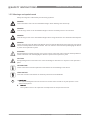
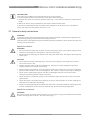
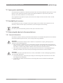
1.3.5 Warnings and symbols used
Safety warnings are indicated by the following symbols.
DANGER!
This information refers to the immediate danger when working with electricity.
DANGER!
This warning refers to the immediate danger of burns caused by heat or hot surfaces.
DANGER!
This warning refers to the immediate danger when using this device in a hazardous atmosphere.
DANGER!
These warnings must be observed without fail. Even partial disregard of this warning can lead to
serious health problems and even death. There is also the risk of seriously damaging the device
or parts of the operator's plant.
WARNING!
Disregarding this safety warning, even if only in part, poses the risk of serious health problems.
There is also the risk of damaging the device or parts of the operator's plant.
CAUTION!
Disregarding these instructions can result in damage to the device or to parts of the operator's
plant.
INFORMATION!
These instructions contain important information for the handling of the device.
LEGAL NOTICE!
This note contains information on statutory directives and standards.
• HANDLING
This symbol designates all instructions for actions to be carried out by the operator in the
specified sequence.
i RESULT
This symbol refers to all important consequences of the previous actions.
10
www.honeywell.com/ps
34-VF-25-47 iss. 3 GLO Jan 13 US
DEVICE DESCRIPTION 2
VERSAFLOW SONIC 2000 / TWS 2000
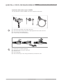
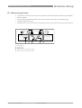
2.1 Scope of delivery
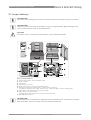
INFORMATION!
Do a check of the packing list to make sure that you have all the elements given in the order.
INFORMATION!
Inspect the cartons carefully for damages or signs of rough handling. Report damage to the
carrier and to the local office of the manufacturer.
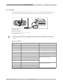
CAUTION!
The device arrives in a plastic trunk on wheels, unless ordered otherwise.
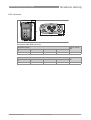
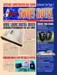
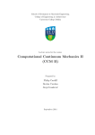
Figure 2-1: Scope of delivery
Product documentation, factory calibration report
Trunk on wheels
Carrying bag
Tray with one or two rails
Metal / textile straps for mounting rail(s) and converter
Sensor(s) with fixing units (small version 1, medium version 2 sensors)
2 Transducers (small versions: 2 MHz, medium version: 1 MHz), including 3 m cable, coupling grease
7 Power adapter including plugs for EU, UK, US and AUS
8 USB memory stick, measure band
optionally I/O box and/or temperature sensors, PC connection cable
9 TWS 2000 Signal converter
1
2
3
4
5
6
INFORMATION!
Delivered content can be different, dependent on the ordered version. A checklist is included
with the product, check if all items on this checklist are delivered.
34-VF-25-47 iss. 3 GLO Jan 13 US
www.honeywell.com/ps
11
2 DEVICE DESCRIPTION
VERSAFLOW SONIC 2000 / TWS 2000
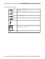
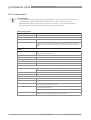
2.2 Nameplates
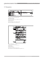
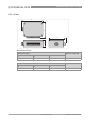
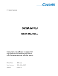
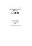
Figure 2-2: Nameplate flow sensor
1
2
3
4
5
6
7
8
Ambient temperature operating range
Protection category
Calibration number
Process temperature (-40...+200°C for XT version)
Manufacturing year
Serial number
Device type (yyy = small, medium or large)
Name and address of the manufacturer
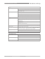
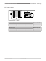
Figure 2-3: Nameplate converter
1
2
3
4
5
6
12
Name and address of the manufacturer
Device type
Serial number
Manufacturing year
Protection class and temperature data
Treat device as electronic garbage according WEEE rules.
www.honeywell.com/ps
34-VF-25-47 iss. 3 GLO Jan 13 US
DEVICE DESCRIPTION 2
VERSAFLOW SONIC 2000 / TWS 2000
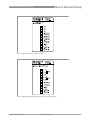
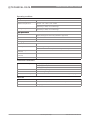
Figure 2-4: Nameplate I/O box, standard version
Figure 2-5: Nameplate I/O box with 2 temperature transmitters included.
34-VF-25-47 iss. 3 GLO Jan 13 US
www.honeywell.com/ps
13
2 DEVICE DESCRIPTION
14
VERSAFLOW SONIC 2000 / TWS 2000
www.honeywell.com/ps
34-VF-25-47 iss. 3 GLO Jan 13 US
VERSAFLOW SONIC 2000 / TWS 2000
INSTALL FOR FLOW MEASUREMENT 3
INFORMATION!
Four steps are needed to start a measurement on a new location:
1. Find a suitable location and determine some basic data of the pipe.
2. Initialise the converter and enter the data from step 1. The converter advises a measurement
mode.
3. Mount the sensor rails as advised for the chosen measurement mode.
4. Perform an optimisation loop and make small changes in the position of the transducers.
These four steps are described in section 3.2...3.5.
3.1 General safety instructions
WARNING!
In general, devices from the manufacturer may only be installed, commissioned, operated and
maintained by properly trained and authorized personnel.
This document is provided to help you establish operating conditions, which will permit safe and
efficient use of this device.
Specific for sensors:
WARNING!
• Be careful when locking the rail back on to the mounting units as your fingers may get stuck
between rail and pipe it is mounted on. This may cause injury.
• Be careful when mounting the fixation units using the metal strap. The edge of the strap may
cause injury.
CAUTION!
• Do not bend the metal mounting strap. This may cause improper mounting of the fixation
units of the sensor rails.
• Protect the pipe contact side of the transducer. Scratches or other damages may have a
negative impact on its proper functioning.
• Before fitting the transducer to the transducer knob in the sensor rail, check the connection
groove of the transducer cover for damages or dirt. Clean or replace when dirty or damaged.
• Check sensor cabling with regular intervals for damages and wear as this may cause
improper functioning. Replace when necessary.
• Check presence of sufficient grease on the transducer pipe contact side in case of acoustic
signal failure.
• Check the sensor rail sliding area regularly for dirt or other pollution or excess coupling fat,
that may cause improper functioning.
• Excess of coupling fat may be removed from the sensor rails and transducers with a dry piece
of cloth. Coupling fat on the converter housing may be removed using soapy water.
Specific for converters:
WARNING!
Be careful moving the handle of the converter, as your fingers may get stuck between the handle
and the housing of the converter. This may cause injury.
34-VF-25-47 iss. 3 GLO Jan 13 US
www.honeywell.com/ps
15
3 INSTALL FOR FLOW MEASUREMENT
VERSAFLOW SONIC 2000 / TWS 2000
CAUTION!
• In order to comply with the EMC directive 2004/108/EC, I/O cables that provide a galvanic
connection to the should have a maximum total length of 3 meter.
• When not used, put the connector covers of the connectors on the bottom side of the
converter in place. This to prevent improper functioning caused by dust/dirt.
• When the sensor cables are connected while the converter is positioned on a flat surface,
turn the handle fully backwards (towards the housing) in order to prevent excess stress on
the sensor cables.
• In order to keep the battery at an optimum condition the battery should be charged at least
once every 6 months.
• If the main battery is empty for a period longer than one year, the backup battery of the real
time clock may run empty.
• The protection degree of the battery charger / mains adapter is IP 40 / NEMA 1. It should be
protected against moisture entering.
• To prevent damage due to vibrations, do not firmly attach the converter to or place it on top of
a vibrating object.
3.2 Step 1: Find location and determine data
CAUTION!
Do not start to mount the rails yet! Step 1 is only meant to find a suitable location for a
measurement. The installation itself will be done in Step 3.
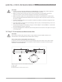
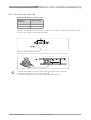
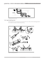
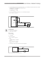
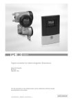
Inlet, outlet and recommended mounting area
To perform an accurate flow measurement preferably mount the sensor rail at least 10 DN
downstream of a flow disturbance like elbows, valves, headers or pumps. Follow the given
installation recommendations.
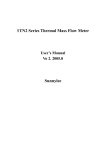
Figure 3-1: Inlet, outlet and recommended mounting area
1 Min. 10 DN
2 Min. 5 DN
3 Recommended installation location (120°)
16
www.honeywell.com/ps
34-VF-25-47 iss. 3 GLO Jan 13 US
VERSAFLOW SONIC 2000 / TWS 2000
INSTALL FOR FLOW MEASUREMENT 3
CAUTION!
Make sure that the rail is not mounted at the highest point (risk for air bubbles) or at the lowest
point (risk for particles) of the pipe.
Long horizontal pipes
• Install on slightly ascending pipe section.
• If not possible, make sure that the flow velocity is high enough to prevent air, gas or vapor to
collect in upper part.
• In partially filled pipes, the clamp-on flowmeter will report incorrect flow rates, or not
measure.
Figure 3-2: Long horizontal pipes
Vertical pipelines
CAUTION!
Make sure that the pipe is fully filled at all times.
INFORMATION!
Both ascending and descending flow directions are measurable.
Figure 3-3: Mounting on vertical pipelines is possible
34-VF-25-47 iss. 3 GLO Jan 13 US
www.honeywell.com/ps
17
3 INSTALL FOR FLOW MEASUREMENT
VERSAFLOW SONIC 2000 / TWS 2000
Open feed or discharge
Install meter on a lowered section of the pipe to make sure that there is a full pipe condition.
Figure 3-4: Open feed or discharge
Down going pipeline over 5 m / 16 ft length
Install an air vent downstream of the flowmeter to prevent vacuum. It may cause gases to come
out of solution (cavitate) that prevent a proper measurement.
Figure 3-5: Down going pipeline over 5 m / 16 ft length
Position of control valve
Always install control valves downstream of the flowmeter in order to avoid cavitation or
distortion of the flow profile.
Figure 3-6: Position of control valve
18
www.honeywell.com/ps
34-VF-25-47 iss. 3 GLO Jan 13 US
VERSAFLOW SONIC 2000 / TWS 2000
INSTALL FOR FLOW MEASUREMENT 3
Position of pump
CAUTION!
Never install the flowmeter at the suction side of a pump in order to avoid cavitation or flashing
in the flowmeter.
Figure 3-7: Position of pump
Determine data and dimensions of pipe
CAUTION!
The next data must be available before proceeding with Step 2.
• Use the supplied tape measure to determine the outside diameter of the pipe.
• Determine the pipe wall thickness. A pipe wall thickness gauge or pipe tables can be used for
this.
• Find out what the material of the pipe is.
• If the pipe has a liner, find out the liner material and the thickness of the liner.
34-VF-25-47 iss. 3 GLO Jan 13 US
www.honeywell.com/ps
19
3 INSTALL FOR FLOW MEASUREMENT
VERSAFLOW SONIC 2000 / TWS 2000
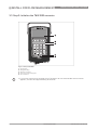
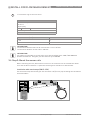
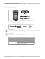
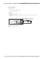
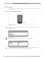
3.3 Step 2: Initialise the TWS 2000 converter
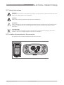
Figure 3-8: Keys TWS 2000
1
2
3
4
5
TFT Display
Navigation keys
Quick access keys
Text and numerical keypad
On / off button
• Turn on the converter by pressing the on / off button for one second. Wait until the menu
appears, this will take approximately 30 seconds.
20
www.honeywell.com/ps
34-VF-25-47 iss. 3 GLO Jan 13 US
VERSAFLOW SONIC 2000 / TWS 2000
INSTALL FOR FLOW MEASUREMENT 3
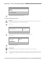
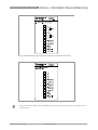
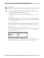
INFORMATION!
FIRST TIME USE:
When the TWS 2000 converter is started for the first time, the startup menu will be shown. In this
menu, set the language, time and date.
To show the menu again at the next startup, select "Settings and information Device Startup sequence? Yes".
First time use
Menu
Language English
Time and date
Units
Continue
13-04-2010 14:11:09
13 MB free
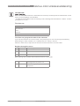
First time use, program the units in the converter
If you use the converter for the first time, it will prompt you for the unit setting automatically.
Otherwise go to menu number 2.4.1 ("Measurement Setup Units").
Choose in each line the required unit with the buttons as shown in the next table.
Navigate through the menu
Back
Back one page
∧
Up
Up one line
∨
Down
Down one line
Forward
Enter item to edit or to select it
When editing, only the Back and Forward buttons are functional:
Back
Delete previous character or leave item
unchanged when at position one
Forward
Move cursor right, accept item when at
last position
34-VF-25-47 iss. 3 GLO Jan 13 US
www.honeywell.com/ps
21
3 INSTALL FOR FLOW MEASUREMENT
VERSAFLOW SONIC 2000 / TWS 2000
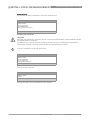
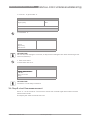
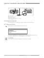
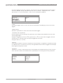
REGULAR USE:
If the device has been used before, the screen will look like:
Menu
Installation Measurement
View logged data
File Management
Settings and information
13-04-2010 14:11:09
13 MB free
Program the converter
CAUTION!
Normally, all settings are saved in a site file. To load the default values, load the default site file
via "Measurement > Load file".
If needed you can recover the factory settings for the site file via "Settings and Information >
Load factory settings". Previous saved site files are kept during this process.
• Select "Installation" from the main menu.
Menu
Installation Measurement
View logged data
File management
Settings & information
13-04-2010 14:11:09
13 MB free
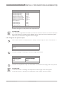
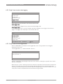
The next screen is shown:
1.1
1 pipe / 1 path 1 pipe / 2 path
2 pipes
13-04-2010 14:11:09
13 MB free
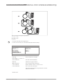
See the next figure for an explanation of the options:
22
www.honeywell.com/ps
34-VF-25-47 iss. 3 GLO Jan 13 US
INSTALL FOR FLOW MEASUREMENT 3
VERSAFLOW SONIC 2000 / TWS 2000
Figure 3-9: System configuration possibilities
1 1 pipe / 1 path
2 1 pipe / 2 path
3 2 pipes
• Choose the desired configuration.
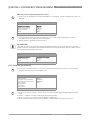
• In the next screen, fill in the data that was found in Step 1.
1.2
Pipe tag
Outer diameter
Material
Wall thickness
Liner material
Liner thickness
< Previous | Next > 13-04-2010 14:11:09
Pipe1
100.00 mm
Carbon steel
5.00 mm
Epoxy
0.50 mm
13 MB free
Pipe tag
Enter a name for the pipe
Press again "" and "".
Outer diameter
Use the outside diameter
Material
Choose the right material
Wall thickness
Fill in the pipe wall thickness
Liner material
Select whether there is a liner or not
Liner thickness
Fill in the liner thickness
The liner thickness will only be shown if a liner
material is chosen.
Choose next
34-VF-25-47 iss. 3 GLO Jan 13 US
www.honeywell.com/ps
23
3 INSTALL FOR FLOW MEASUREMENT
VERSAFLOW SONIC 2000 / TWS 2000
CAUTION!
Inaccurate input of the outside diameter will affect the accuracy of the measured flow rate.
INFORMATION!
In case of a two pipe configuration, the converter will ask if the data entered for pipe 1 has to be
used for pipe 2 too.
Menu 1.2 and 1.3 are shown again to enter the data for the second pipe.
1.3
Fluid
VoS Fluid
Viscosity
< Previous | Next > 13-04-2010 14:11:09
Water
1485.0 m/s
1 mm2/s
13 MB free
Fluid
Select the correct fluid from the table.
VoS Fluid
Velocity of Sound of the selected fluid. Only change it if
highly accurate values are available, for instance
temperature compensated.
Viscosity
Only change it if the viscosity is well known.
Choose next
An advise is given in the next menu:
CAUTION!
Find the calibration numbers that are noted on the labels on the cable of each transducer. Make
sure that both transducers have the same calibration number as shown by the converter.
1.7
Transducer set
Calibration number
Number of traverses
< Previous | Next > 13-04-2010 14:11:09
Ta
522505050
2
13 MB free
CAUTION!
Normally, do not change the settings in this menu.
INFORMATION!
In case of a two sensor configuration, this loop will be shown twice. After installing the first
transducer the converter will produce a second advice for the second installation.
Transducer set
Select the value that is on the label on the transducer
cable.
Note: A maximum of three transducer sets can be
programmed in the converter, called Ta, Tb or Tc.
24
www.honeywell.com/ps
34-VF-25-47 iss. 3 GLO Jan 13 US
VERSAFLOW SONIC 2000 / TWS 2000
INSTALL FOR FLOW MEASUREMENT 3
Calibration number
Compare the calibration number with the number on the
transducer cable. If needed, select a different transducer
set to change the calibration number.
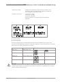
Number of traverses
1 traverse = Z mode
2 traverses = V mode
4 traverses = W mode
See figure below for an explanation of the number of
traverses.
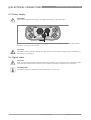
Figure 3-10: Number of traverses
1 1 traverse (Z mode)
2 2 traverses (V mode)
3 4 traverses (W mode)
The best suitable sensor is automatically selected from the available sensor types in the
converter and the appropiate number of traverses is indicated. If none of the sensors is suitable,
the converter will show "Transducer set : None".
Pipe
Available sensor
DN15...150
Small 2 MHz, 1 rail
DN50...250
Medium 1 MHz, 1 rail
DN200...750
Medium 1 MHz, 2 rails
DN400...1500
Medium 1 MHz, 2 rails
Traverse mode
CAUTION!
Normally, install the sensors as advised. If the quality of the pipe walls is poor and / or in case of
scaling inside the pipes, try to decrease the amount of traverses or (if possible) use a medium
sensor instead of a small sensor.
34-VF-25-47 iss. 3 GLO Jan 13 US
www.honeywell.com/ps
25
3 INSTALL FOR FLOW MEASUREMENT
VERSAFLOW SONIC 2000 / TWS 2000
• Press Next to go to the next menu:
1.8
Advised sensor position
34.30 mm
Signal quality
0%
< Previous | Next > 13-04-2010 14:11:09
13 MB free
Advised distance [mm]
Number of rails needed
< 190
1
≥ 190
2
INFORMATION!
The maximum distance that can be covered with 1 rail is 195 mm.
The minimum distance for two rails is 180 mm.
INFORMATION!
On request it is possible to use the large rail of the VersaFlow Sonic 1000 / TWS 9000 with
0,5 MHz transducers. Using this you can measure up to DN4000.
3.4 Step 3: Mount the sensor rails
Before mounting the rails, determine the colors on the connectors of the transducers. Make
sure that the blue transducer is upstream and the green transducer is downstream.
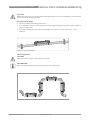
Installation with metal straps (DN15...250)
Put the metal straps around the pipe. Put the sensor rail(s) on the pipe including the transducers
with fixed cables.
26
www.honeywell.com/ps
34-VF-25-47 iss. 3 GLO Jan 13 US
VERSAFLOW SONIC 2000 / TWS 2000
1
2
3
4
5
6
INSTALL FOR FLOW MEASUREMENT 3
Insert straps in the lower opening.
Repeat the same for the other strap.
Pull the straps around the pipe.
Insert the straps in the upper opening.
Pull the straps tight.
Use an allan key nr 5 (or a big screwdriver) to fixate the rails.
34-VF-25-47 iss. 3 GLO Jan 13 US
www.honeywell.com/ps
27
3 INSTALL FOR FLOW MEASUREMENT
VERSAFLOW SONIC 2000 / TWS 2000
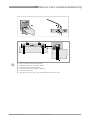
Installation with textile straps (> DN250)
For pipe diameters above DN250, the textile straps must be used.
28
1
2
3
4
Insert the long strap in the upper opening.
Insert the short strap in the lower opening at the other side of the rail.
Pull the strap around the pipe.
Fix the strap, as indicated below.
1
2
3
4
5
Push lever to create a opening.
Insert the textile strap as indicated.
Release lever.
Pull strap tight.
Use an allan key nr 5 (or a big screwdriver) to fixate the rails.
www.honeywell.com/ps
34-VF-25-47 iss. 3 GLO Jan 13 US
VERSAFLOW SONIC 2000 / TWS 2000
INSTALL FOR FLOW MEASUREMENT 3
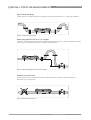
3.4.1 2 or 4 traverses with 1 rail
Applicable diameters with one rail:
Number of
traverses
Diameter range
2
DN15...250
4
DN15...150
Put the first transducer at position "0". Put the other transducer at the advised distance, shown
on the screen in Step 2. See the figures below.
Figure 3-11: Advised distance with one rail
1 Advised distance is measured from center first transducer to indicator at second transducer.
• Unlock the transducer by turning the locking knob 2 counter clockwise.
• Slide the transducer 1 to the new position 3.
• Lock the transducer by turning the locking knob 2 clockwise.
34-VF-25-47 iss. 3 GLO Jan 13 US
www.honeywell.com/ps
29
3 INSTALL FOR FLOW MEASUREMENT
VERSAFLOW SONIC 2000 / TWS 2000
3.4.2 2 traverses with 2 rails
Applicable diameters with two rails:
Number of
traverses
Diameter range
2
DN200...750
INFORMATION!
The two rails must be installed in a straight line.
Figure 3-12: Mounting 2 rails in V-mode (2 traverses)
1 Advised distance
2 Distance between 2 rails
• Mount the first rail on the pipe. Make sure that you mount the rail in line with the pipe!
• Position the left transducer in any position X (see next section).
• Mount the second rail (align it with the first rail) at a distance 2 to arrange that the transducer
in the second rail is within the range it can be moved.
• The advised distance 1 is defined from the center of the left transducer to the left side of the
right transducer. Put the second transducer at position Z = advised distance 1 + X - distance
2 - 415 mm / 16.3".
30
www.honeywell.com/ps
34-VF-25-47 iss. 3 GLO Jan 13 US
VERSAFLOW SONIC 2000 / TWS 2000
INSTALL FOR FLOW MEASUREMENT 3
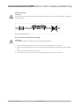
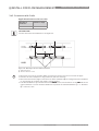
3.4.3 1 traverse with 2 rails (DN400...1500)
Applicable diameters with two rails:
Number of
traverses
Diameter range
1
DN400...1500
• Measure the outer diameter of the pipe with the tape measure.
• Calculate the half of the outer diameter.
• Start at the left side of the rail and locate the opposite side using the calculated half of the
outer diameter.
• Put a mark at this position.
• Repeat this at the right side of the rail.
• Draw a line between the two markings.
• Mount the DOWN rail in such a way that the transducer is at the marked location.
Figure 3-13: Mounting second rail in Z mode (1 traverse) using a reference point
1 Measure the distance between the transducer of the UP rail and the reference point.
2 Add the advised distance to determine the position of the second transducer.
34-VF-25-47 iss. 3 GLO Jan 13 US
www.honeywell.com/ps
31
3 INSTALL FOR FLOW MEASUREMENT
VERSAFLOW SONIC 2000 / TWS 2000
Figure 3-14: Mounting second rail in Z mode (1 traverse) without using a reference point
1 Advised distance 1 = 2 + 3
3.4.4 Apply coupling grease
Push the buttons of the fixing units to unlock and tilt the rail. Then put some coupling grease on
the transducers and put the rail back by clicking.
Figure 3-15: Greasing transducers
32
www.honeywell.com/ps
34-VF-25-47 iss. 3 GLO Jan 13 US
INSTALL FOR FLOW MEASUREMENT 3
VERSAFLOW SONIC 2000 / TWS 2000
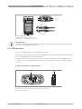
3.4.5 Connect the sensor cable
1
1
2
2
1
1
2
3
ABC
DEF
4
5
6
GHI
JKL
MNO
7
8
9
PQRS
TUV
WXYZ
+/-
0
EXP
A/a
-
I/O
DISPLAY
LOGGER
MENU
2
Figure 3-16: Connecting signal cables
1 Connector for "UP" transducer (blue)
2 Connector for "DOWN" transducer (green)
INFORMATION!
After mounting the transducers in the proper position, it takes up to 60 seconds to find a signal.
INFORMATION!
The signal strength is given and can be qualified as shown:
Signal strength
Qualification
> 75%
High signal
50...75%
Fairly high signal
10...50%
Low signal
< 10%
Bad or no signal
Check settings in menu, change transducer distance
until there is at least a low signal.
34-VF-25-47 iss. 3 GLO Jan 13 US
www.honeywell.com/ps
33
3 INSTALL FOR FLOW MEASUREMENT
VERSAFLOW SONIC 2000 / TWS 2000
1.8
Advised sensor position
52.18 mm
Signal quality
78%
< Previous | Next > 13-04-2010 14:11:09
13 MB free
• Proceed with the optimization loop in step 4.
3.5 Step 4: Optimization loop
CAUTION!
If the actual sensor position is not entered accurately, the sound velocity can not be calculated
correctly and optimization of the sensor position will fail.
• Press "".
1.10
Advised sensor position
Actual sensor position
66.05 mm
66.05 mm
< Previous | Next > 13-04-2010 14:11:09
13 MB free
• Make sure that the transducers are mounted at the advised distance.
• Press Next .
1.12
Volume flow
Velocity of sound
Signal quality
50 m3/h
1481.3 m/s
69%
Optimize position < Previous | Next >
13-04-2010 14:11:09
13 MB free
• Press Optimize position .
INFORMATION!
The optimization loop uses the measured VoS and compares it to the entered VoS.
• The optimization loop will give a new advise on the transducer distance. Slide the transducers
to the new position. Repeat this loop until the advised distance does not change more than 1%
or 1 mm.
34
www.honeywell.com/ps
34-VF-25-47 iss. 3 GLO Jan 13 US
INSTALL FOR FLOW MEASUREMENT 3
VERSAFLOW SONIC 2000 / TWS 2000
• In menu 1.12, press Next .
1.19
Sensor 1 status
Signal quality
Installed
80 %
< Previous | Next > 13-04-2010 14:11:09
13 MB free
• Press Next .
1.20
Site name test
Cancel
Skip saving
Save site file
13-04-2010 14:11:09
13 MB free
INFORMATION!
You can save the settings in a site file, so they can be used again later when measuring at the
same site (location).
• Enter a file name.
• Select Save site file .
Measurement
Site name
test
Display measurement Load site
Save current site
Setup
13-04-2010 14:11:09
13 MB free
INFORMATION!
The device is now ready to measure.
3.6 Step 5: start flow measurement
Press "" on the converter. The converter checks the received signal and initiates the flow
measurement mode.
The display will show the actual flow now.
34-VF-25-47 iss. 3 GLO Jan 13 US
www.honeywell.com/ps
35
3 INSTALL FOR FLOW MEASUREMENT
VERSAFLOW SONIC 2000 / TWS 2000
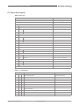
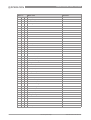
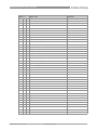
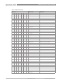
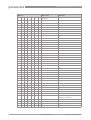
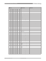
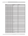
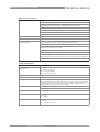
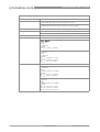
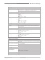
3.7 Error messages
Error
code
Group
message
F (bold)
Error message
Description
Error handling
error in
device
no measurement possible,
measured values are not valid
repair or replace device and/or CPU;
contact manufacturer service center
F
application
error
no measurement possible, but
device ok
check parameter settings / power
off - wait 5 seconds - power on
device
S
out of
specification
unreliable measurement
maintenance required, check
flowprofile
C
check in
progress
test function is active, device is
stand-by
wait until finished
I
information
no direct impact on measurements
no action needed
F (bold)
IO 1 (or IO 2)
error or failure of IO Module 1 (or 2)
try to load settings (menu C8.6.3);
if error does not disappear, replace
electronics unit
F (bold)
parameter
error or failure of data manager,
parameter or hardware error
try to load settings (menu C8.6.3);
if error does not disappear, replace
electronics unit
F (bold)
configuration
incorrect configuration or no
confirmation
confirm change of module;
if configuration is unchanged,
replace electronics unit
F (bold)
display
error of failure of display unit,
parameter or hardware error
defect; replace electronics units
F (bold)
current output
A (or B, C)
error or failure of the current output
A (or B, C), parameter or hardware
error
defect; replace electronics units
F (bold)
software user
interface
F (bold)
hardware
settings
detected hardware and set hardware
settings do not match
follow display instructions
F (bold)
hardware
detection
hardware can not be detected
defect; replace electronics units
F (bold)
RAM/ROM
error IO 1
(or IO 2)
F (bold)
communication
dsp-up
no communication between DSP and
microprocessor PCB
contact manufacturer service center
F (bold)
front end
malfunctioning of front end PCB
contact manufacturer service center
F (bold)
uproc
malfunctioning of microcontroller
PCB
contact manufacturer service center
F (bold)
dsp
malfunctioning of DSP
contact manufacturer service center
F
empty pipe
signal lost at two paths
check process conditions
F
flow > max 1
max volume flow exceeded for pipe 1 check parameter in menu C1.7.1
F
flow > max 2
max volume flow exceeded for pipe 2 check parameter in menu C1.7.1
F
open circuit A
(or B, C)
current on current output A (or B, C)
too low
check cable or reduce resistance
(< 1000 Ohm)
F
over range A
(or B, C)
current on current output A (or B, C)
is limited by parameter setting
extend upper or lower limit for
current output in menu C5.2.8
F
over range A
(or B, D)
pulse on frequency output A (or B, D)
is limited by parameter setting
extend upper or lower limit for
frequency output in menu C5.3.7
F
active settings
error during CRC check (Cyclic
Redundancy Check) of the active
settings
load settings; factory setting, back
up 1 or back up 2
36
defect; replace electronics units
defect; replace electronics units
www.honeywell.com/ps
34-VF-25-47 iss. 3 GLO Jan 13 US
VERSAFLOW SONIC 2000 / TWS 2000
INSTALL FOR FLOW MEASUREMENT 3
F
factory settings
error during CRC check of factory
settings
F
back up 1 (or 2)
settings
error during CRC check of back up 1
(or 2) settings
F
signal lost
path 1
signal lost at path 1
check signal cable / check for pipe
obstructions
F
signal lost
path 2
signal lost at path 2
check signal cable / check for pipe
obstructions
F
pipe/sens1
param.
unrealistic parameter settings for
pipe in combination with path 1
check parameters in menu X6
F
pipe/sens2
param.
unrealistic parameter settings for
pipe in combination with path 2
check parameters in menu X6
S
unreliable 1
unreliable measurement at pipe 1
check process conditions for gas
bubbles, solids
S
unreliable 2
unreliable measurement at pipe 2
check process conditions for gas
bubbles, solids
S
zero converter
invalid value at power up
power off - wait 5 seconds - power
on device
S
overflow
counter 1 (or 2,
3)
counter is overflowing and will start
again at zero
no action needed
S
backplane
invalid
error during CRC check of
backplane
restore data records on backplane
I
counter 1 (or 2,
3) stopped
counter has stopped
reset counter in menu C8.9.1
(or C8.9.2, C8.9.3)
I
control input A
(or B) active
information only
no action needed
I
over range
display 1 (or 2)
1st row on 1st (or 2nd) measurement
page is limited by parameter setting
extend upper or lower limit for
limitation in menu C8.3.4
I
backplane
sensor
incompatible data sensor on
backplane
I
backplane
settings
incompatible data on backplane
I
backplane
difference
different data on backplane and
display
I
optical
interface
optical interface is operational, local
display can not be used
I
softw sync
error
incompatible DSP and
microprocessor software
34-VF-25-47 iss. 3 GLO Jan 13 US
www.honeywell.com/ps
37
3 INSTALL FOR FLOW MEASUREMENT
38
www.honeywell.com/ps
VERSAFLOW SONIC 2000 / TWS 2000
34-VF-25-47 iss. 3 GLO Jan 13 US
VERSAFLOW SONIC 2000 / TWS 2000
INSTALL FOR ENERGY MEASUREMENT 4
The combination of the measured flow rate and a temperature difference over a device can be
used to determine the amount of energy used by that device. The temperature difference can
either be programmed manually in the converter or be measured with temperature
transmitters, connected to an optional I/O box. in this case, the temperature difference is
determined by measuring the temperature before and after the heat/cold producer/consumer.
Figure 4-1: Energy measurement of heat user
1
2
3
4
5
6
Mounted rail (in any measuring mode)
PT 100 temperature sensor, before the heat/cold producer/consumer
PT 100 temperature sensor, after the heat/cold producer/consumer
Radiator
Optional I/O box with temperature option
Converter
INFORMATION!
Please find more detailed information in the next sections to set up an energy measurement.
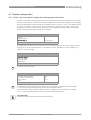
4.1 Preparation of energy measurement
1 Install a flow measurement as described in the previous chapter. Make sure that the rail and
converter are installed close to the location of the place where the temperature sensors must
be installed, because of the fixed (limited) length of the sensor cables.
2 Check if temperature transmitters are already available on site.
Transmitters are already available on site:
Make sure that the basis I/O box is used. Connect the temperature transmitters to the 4...20 mA
current input of basic I/O, which is connected to the converter.
Transmitters are not available on site:
Make sure that the Extended I/O box is used. In this version, the temperature transmitters are
included. Optionally, clamp-on PT 100 temperature sensors can be delivered, with a
temperature range of 0...120°C / 32...248°F, including two meter cable and suitable for pipes up
to DN300.
34-VF-25-47 iss. 3 GLO Jan 13 US
www.honeywell.com/ps
39
4 INSTALL FOR ENERGY MEASUREMENT
VERSAFLOW SONIC 2000 / TWS 2000
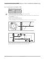
4.2 Mechanical installation
Mounting of temperature sensors
The delivered PT 100 sensors are clamp-on elements. Clamp them on the pipe with the hose
clamp.
INFORMATION!
Mount the temperature sensors close to the rail for flow measurement. All cables have a fixed
length!
Figure 4-2: Mounting PT 100 with hose clamp
1 PT 100 temperature transmitter
2 Hose clamp
If the temperature sensors on the pipe have temperature transmitters 4...20 mA it is possible to
make use of the standard I/O box.
• Connect the PT 100 elements to the I/O box according to the sticker on the I/O box.
40
www.honeywell.com/ps
34-VF-25-47 iss. 3 GLO Jan 13 US
VERSAFLOW SONIC 2000 / TWS 2000
INSTALL FOR ENERGY MEASUREMENT 4
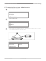
Figure 4-3: Extended I/O box with 2 temperature transmitters included for PT 100 sensors.
Figure 4-4: Basic I/O box for 4...20 mA temperature transmitters
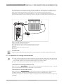
• Plug the connector 2 of the I/O box 3 in the connector 1 of the converter, as shown in the
figure below.
34-VF-25-47 iss. 3 GLO Jan 13 US
www.honeywell.com/ps
41
4 INSTALL FOR ENERGY MEASUREMENT
VERSAFLOW SONIC 2000 / TWS 2000
Figure 4-5: I/O box
1 I/O connector on converter
2 Connector of I/O box
3 I/O box with screw terminals for 1 mm2 wiring
4 Screw terminal pin 1...15
4.3 Program the converter
Three settings must be programmed in order to measure the amount of energy.
4.3.1 Program the I/O input
• Go to menu nr. 2.4.5 via "Measurement Setup I/O"
2.4.5
Current output
Current inputs Status output / limit switch
Frequency / pulse output
Simulation
13-04-2010 14:11:09
13 MB free
If the recommended Honeywell energy set is used, the standard settings are correct. The
temperature range is 4 mA = 0°C / 32°F and 20 mA = 120°C / 248°F:
INFORMATION!
On the converter, you must scroll down in the menu to see all settings.
42
www.honeywell.com/ps
34-VF-25-47 iss. 3 GLO Jan 13 US
VERSAFLOW SONIC 2000 / TWS 2000
INSTALL FOR ENERGY MEASUREMENT 4
2.4.5.2
Function Extended range A 0%
Extended range A 100%
Extended range B 0%
Extended range B 100%
Temperature range A 0%
Temperature range A 100%
Temperature range B 0%
Temperature range B 100%
Time constant A
Time constant B
4 mA trimming A
20 mA trimming A
4 mA trimming B
20 mA trimming B
13-04-2010 14:11:09
On
3.6 mA
21 mA
3.6 mA
21 mA
0.0 °C
120.0 °C
0.0 °C
120.0 °C
1s
1s
4 mA
20 mA
4 mA
20 mA
13 MB free
If another energy set is used, teach in the required values.
INFORMATION!
The "Extended range A/B 0% and 100%" are meant for an alarm function. If a value is measured
that is lower than the "Extended range A/B 0%" value or higher than the "Extended range A/B
100%" value, an event will be logged in the event logger.
4.3.2 Program the process input
• Go to menu 2.4.2.3.1 via "Measurement Setup Process input Heat Function off "
2.4.2.3.1
Heating Cooling
Off
13-04-2010 14:11:09
13 MB free
• Choose "Heating" or "Cooling" to activate energy measurement.
2.4.2.3
Function
Temperature input Sensor location
Fluid
13-04-2010 14:11:09
Heating
Terminal A at supply
Supply
Water
13 MB free
• Choose in "Temperature input " which sensor is is located at the supply side of the process.
INFORMATION!
In case the function is "Heating", the temperature at the "supply" side is the highest.
In case the function is "Cooling", the temperature at the "supply" side is the lowest.
34-VF-25-47 iss. 3 GLO Jan 13 US
www.honeywell.com/ps
43
4 INSTALL FOR ENERGY MEASUREMENT
VERSAFLOW SONIC 2000 / TWS 2000
Manually entering the temperature values
• If there are no temperature sensors available for connecting, set the "Temperature input" to
"Manual".
2.4.2.3
Function
Temperature input Supply temperature
Return temperature
Sensor location
Fluid
13-04-2010 14:11:09
Heating
Manual
80.0 °C
120.0 °C
Supply
Water
13 MB free
• Set the location of the flow sensor (supply or return side of the installation) in order to
calculate the correct specific heat of the liquid.
• Check whether the shown fluid is correct.
INFORMATION!
The type of fluid is set in the flow sensor installation wizard. In case the fluid is set to waterglycol mixture in the flow sensor installation wizard the concentration of glycol in water can be
set in the heating/cooling setup menu.
2.4.2.3
Function
Temperature input Sensor location
Fluid
13-04-2010 14:11:09
Heating
Terminal A at supply
Supply
Water
13 MB free
4.3.3 Program the counters
• Go to menu 2.4.6 and select a counter for counting energy. Use counter 3 or 4 for energy
measurements as they have a higher limit.
2.4.6.1
Function of counter Measurement
Low flow cutoff threshold
Low flow cutoff hysteresis
Preset value
Reset counter
Set counter
Stop counter
13-04-2010 14:11:09
+ counter
Power
0.000 kW
0.000 kW
0 kJ
13 MB free
• At the "Function of counter", select "Sum" for counting both positive and negative energy
flows.
• Select "+ counter" for only counting positive energy flows.
• Select "- counter" for only counting negative energy flows.
• At the "Measurement" option, select "Power". The energy value counter unit is kJ.
44
www.honeywell.com/ps
34-VF-25-47 iss. 3 GLO Jan 13 US
VERSAFLOW SONIC 2000 / TWS 2000
INSTALL FOR ENERGY MEASUREMENT 4
4.4 Start measurement
The following parameters are available when heating or cooling measurement is switched on:
•
•
•
•
Temperature A/B
Temperature difference
Themal power (power)
Thermal energy (totalized power)
To setup the display to view those parameters please refer to the display setup paragraph.
The unit for energy measurement can standard be set to Joule (kilo, mega, giga), Wh (kilo, mega)
or BTU (kilo, million (MM)). In case any other unit is required the free unit can be used. To setup
the free unit go to "Measurement Setup Units ". Select the power or energy parameter,
then select "Free unit". Enter the text for the unit, then the factor for the unit entered.
The factor for energy is the amount of Joules in the free unit. The factor for power is the amount
of Watt's in the free unit.
Underneath you find a table with factors for alternative energy units.
Unit of power
Description
W factor
(amount of Watt in unit)
Ton (refrigeration)
A ton of refridgeration is defined
as the cooling power to melt one
short ton (2000 pounds or 907 kg)
of ice in a 24 hour period. This is
equal to 12000 BTU per hour or
3527 W.
3527
kilo calorie per second
Power required to heat 1 kg of
water with 1 degree Celsius in 1
second.
4187
Unit of energy
Description
J factor
(amount of Joule in unit)
Ton-hour (refrigeration)
A ton-hour of refridgeration is
defined as the energy to melt one
short ton (2000 pounds or 907 kg)
of ice.
12660000
kilo calorie per second
Amount of heat required to
increase 1 kg of water with 1
degree Celsius.
4187
Therm
Equal to 100000 BTU
105506000
34-VF-25-47 iss. 3 GLO Jan 13 US
www.honeywell.com/ps
45
4 INSTALL FOR ENERGY MEASUREMENT
46
www.honeywell.com/ps
VERSAFLOW SONIC 2000 / TWS 2000
34-VF-25-47 iss. 3 GLO Jan 13 US
ELECTRICAL CONNECTIONS 5
VERSAFLOW SONIC 2000 / TWS 2000
5.1 Safety instructions
DANGER!
All work on the electrical connections may only be carried out with the power disconnected. Take
note of the voltage data on the nameplate!
DANGER!
Observe the national regulations for electrical installations!
WARNING!
Observe without fail the local occupational health and safety regulations. Any work done on the
electrical components of the measuring device may only be carried out by properly trained
specialists.
INFORMATION!
Look at the device nameplate to ensure that the device is delivered according to your order.
Check for the correct supply voltage printed on the nameplate.
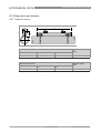
5.2 Location of connectors at the converter
All connectors are located at the bottom side of the converter.
USB
1
4
GHI
2
3
ABC
DEF
5
6
JKL
MNO
7
8
9
PQRS
TUV
WXYZ
+/-
0
EXP
A/a
-
34-VF-25-47 iss. 3 GLO Jan 13 US
I/O
i/o
1
2
DISPLAY
DC in
LOGGER
MENU
www.honeywell.com/ps
47
5 ELECTRICAL CONNECTIONS
VERSAFLOW SONIC 2000 / TWS 2000
5.3 Power supply
WARNING!
Only use the supplied AC charger to charge the battery of the converter!
i/o
USB
1
2
DC in
1
Plug in the connector of the supplied charger at the connector 1. Then insert the main power
connector into your mains outlet.
CAUTION!
The battery status indicator will be accurate after an initial full discharge directly followed by a
full charge of the battery.
5.4 Signal cable
CAUTION!
Find the calibration numbers that are noted on the labels on the cable of each transducer. Make
sure that both transducers have the same calibration number as shown by the converter.
INFORMATION!
The signal cables are prefixed to the transducers in the factory.
48
www.honeywell.com/ps
34-VF-25-47 iss. 3 GLO Jan 13 US
ELECTRICAL CONNECTIONS 5
VERSAFLOW SONIC 2000 / TWS 2000
1
1
2
2
1
1
2
3
ABC
DEF
4
5
6
GHI
JKL
MNO
7
8
9
PQRS
TUV
WXYZ
+/-
0
EXP
A/a
-
I/O
DISPLAY
LOGGER
MENU
2
Figure 5-1: Connecting signal cables
1 Connector for "UP" transducer (blue)
2 Connector for "DOWN" transducer (green)
INFORMATION!
You can measure two paths with this converter simultaneously. Use the left pair of connectors
for path 1 and the right pair for path 2.
5.5 USB connector
There are 2 USB connections available on the converter:
1. Read / write data to a memory stick with the USB connector (the converter acts as the master),
for transferring data (log files and site files).
2. Control the converter with a PC (the converter acts as the slave) for file management. The
memory of the converter appears as a memory in your explorer tree view, just like a memory
stick.
1. Read / write data to a memorystick
Figure 5-2: Connecting a memory stick to the converter
1 Remove the protection cap by turning the knob counter clockwise
2 Insert the memory stick
34-VF-25-47 iss. 3 GLO Jan 13 US
www.honeywell.com/ps
49
5 ELECTRICAL CONNECTIONS
VERSAFLOW SONIC 2000 / TWS 2000
Figure 5-3: Using a memory stick for a measurement
1 Perform a measurement on site and log the data to the memorystick
2 Put the memory stick in your pc and evaluate the measurement.
2. Control the converter with a PC
Figure 5-4: Connecting a pc to the converter
1 I/O connector
2 USB connector
3 optional USB / I/O cable
50
www.honeywell.com/ps
34-VF-25-47 iss. 3 GLO Jan 13 US
ELECTRICAL CONNECTIONS 5
VERSAFLOW SONIC 2000 / TWS 2000
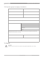
5.6 I/O cable
To use the available inputs and outputs of the converter, you need an optional I/O box. The I/O
box is available in two versions (standard I/O functions and heat measurement version).
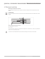
Figure 5-5: I/O box
1 I/O connector on converter
2 Connector of I/O box
3 I/O box with screw terminals for 1 mm2 wiring
4 Screw terminal pin 1...15
• Plug the connector 2 of the I/O box 3 in the connector 1 of the converter. Then use the
connectors 4 to setup the wanted I/O, as shown in the connection diagrams on the next
pages.
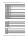
Versions of I/O box
Screw terminal
pin
Standard I/O box
I/O box with heat option
1
Frequency / pulse output D
Frequency / pulse output D
2
Frequency / pulse output D-
Frequency / pulse output D-
3
Status output X
Status output X
4
Status output X-
Status output X-
5
Current output C+
Current output C+
6
Current output C
Current output C
7
Current output C-
Current output C-
8
Current input A+
9
Current input A-
Temperature sensor 1
(PT 100, 4 wire connection)
10
Current input B+
11
Current input B-
12
Not connected
13
Not connected
14
Not connected
15
Not connected
Temperature sensor 2
(PT 100, 4 wire connection)
Table 5-1: Terminals of I/O box
34-VF-25-47 iss. 3 GLO Jan 13 US
www.honeywell.com/ps
51
5 ELECTRICAL CONNECTIONS
VERSAFLOW SONIC 2000 / TWS 2000
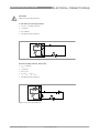
5.7 Connection diagrams
mA meter
0...20 mA or 4...20 mA and other
RL is the internal resistance of the measuring point including the cable
resistance
DC voltage source (Uext), external power supply, any connection polarity
DC voltage source (Uext), observe connection polarity according to
connection diagrams
Internal DC voltage source
Controlled internal power source in the device
Electronic or electromagnetic counter
At frequencies above 100 Hz, shielded cables must be used to connect the
counters.
Ri Internal resistance of the counter
Button, NO contact or similar
Table 5-2: Description of symbols
52
www.honeywell.com/ps
34-VF-25-47 iss. 3 GLO Jan 13 US
ELECTRICAL CONNECTIONS 5
VERSAFLOW SONIC 2000 / TWS 2000
CAUTION!
Observe connection polarity.
4...20 mA current output active
• Uint,nom = 15 VDC nominal
• I ≤ 22 mA
• RL ≤ 600 Ω
• Not galvanically isolated.
Figure 5-6: Current output active Ia
Current output passive, basic I/Os
• Uext ≤ 32 VDC
• I ≤ 22 mA
• U0 ≥ 1.8 V
• RL ≤ (Uext - U0) / Imax
• Not galvanically isolated.
Figure 5-7: Current output passive Ip
34-VF-25-47 iss. 3 GLO Jan 13 US
www.honeywell.com/ps
53
5 ELECTRICAL CONNECTIONS
VERSAFLOW SONIC 2000 / TWS 2000
INFORMATION!
Pulse / frequency output
• Any connection polarity.
• Galvanically isolated.
Pulse/frequency output passive
• Uext ≤ 32 VDC
• fmax in operating menu set to fmax ≤ 100 Hz:
I ≤ 100 mA
open:
I ≤ 0.05 mA at Uext = 32 VDC
closed:
U0, max = 0.2 V at I ≤ 10 mA
U0, max = 2 V at I ≤ 100 mA
• fmax in the operating menu set to 100 Hz < fmax ≤ 10 kHz:
I ≤ 20 mA
open:
I ≤ 0.05 mA at Uext = 32 VDC
closed:
U0, max = 1.5 V at I ≤ 1 mA
U0, max = 2.5 V at I ≤ 10 mA
U0, max = 5.0 V at I ≤ 20 mA
• If the following maximum load resistance RL, max is exceeded, the load resistance RL must be
reduced accordingly by parallel connection of R:
f ≤ 100 Hz: RL, max = 47 kΩ
f ≤ 1 kHz: RL, max = 10 kΩ
f ≤ 10 kHz: RL, max = 1 kΩ
• The minimum load resistance RL, min is calculated as follows:
RL, min = (Uext - U0) / Imax
• Can also be set as a status output; for the electrical connection, see status output connection
diagram.
Pulse/frequency output active
• Unom = 15 VDC
• fmax in operating menu set to fmax ≤ 100 Hz:
I ≤ 20 mA
open:
I ≤ 0.05 mA
closed:
U0, nom = 15 V at I = 20 mA
• fmax in the operating menu set to 100 Hz < fmax ≤ 10 kHz:
I ≤ 20 mA
open:
I ≤ 0.05 mA
closed:
U0, nom = 13.5 V at I ≤ 1 mA
U0, nom = 12.5 V at I ≤ 10 mA
U0, nom = 9.0 V at I ≤ 20 mA
54
www.honeywell.com/ps
34-VF-25-47 iss. 3 GLO Jan 13 US
ELECTRICAL CONNECTIONS 5
VERSAFLOW SONIC 2000 / TWS 2000
• If the following maximum load resistance RL, max is exceeded, the load resistance RL must be
reduced accordingly by parallel connection of R:
f ≤ 100 Hz: RL, max = 47 kΩ
f ≤ 1 kHz: RL, max = 10 kΩ
f ≤ 10 kHz: RL, max = 1 kΩ
• The minimum load resistance RL, min is calculated as follows:
RL, min = (Uext - U0) / Imax
C+
CD
D-
Figure 5-8: Pulse frequency output active Pa
INFORMATION!
• Any connection polarity.
• Galvanically isolated.
Status output
• Uext ≤ 32 VDC
• I ≤ 100 mA
• RL, max = 47 kΩ
RL, min = (Uext - U0) / Imax
• open:
I ≤ 0.05 mA at Uext = 32 VDC
closed:
U0, max = 0.2 V at I ≤ 10 mA
U0, max = 2 V at I ≤ 100 mA
• The output is open when the device is de-energized.
Figure 5-9: Status output / limit switch passive Sp
34-VF-25-47 iss. 3 GLO Jan 13 US
www.honeywell.com/ps
55
5 ELECTRICAL CONNECTIONS
VERSAFLOW SONIC 2000 / TWS 2000
Current input active
• Uint, nom = 15 VDC
• I ≤ 22 mA
• Imax ≤ 26 mA (electronically limited)
• U0, min = 19 V at I ≤ 22 mA
• no HART®
• Not galvanically isolated
• X designates the connection terminals A or B, depending on the version of the signal
converter.
Figure 5-10: Current input active IIna
1 Signal
2 2-wire transmitter (e.g. temperature)
56
www.honeywell.com/ps
34-VF-25-47 iss. 3 GLO Jan 13 US
OPERATION 6
VERSAFLOW SONIC 2000 / TWS 2000
6.1 Display configuration
6.1.1 Step 1: how to set up the display for showing measured values
There are two ways of setting up screens for showing measured values. Standard 4 information
screens can be shown in the measuring mode. Additional screens showing graphs can be added
when the datalogger is used. Setting up the display is done in menu nr. 2.4.3.1 via "Measurement
Setup Display Screen setup". The following menu will be shown. Page 1 and 2 show
parameters in numeric values or bar graphs or both, the graphical page shows trend graphs.
The fourth page shows status and error messages.
2.4.3.1
Page 1
Page 2
Graphical page
Default page 13-04-2010 14:11:09
None (cyclic)
13 MB free
The appearance of the screens can be set. None (cyclic) means that the screen page will cycle
through the 4 screens automatically. It is possible to define the default screen to display, for
instance "1st meas. page".
2.4.3.1.4
None (cyclic)
1st meas. page 2nd meas. page
Graphical page
Status page
13-04-2010 14:11:09
13 MB free
• Select 1st meas. page 2.4.3.1.1
Presentation mode 1 Low flow cutoff threshold
Low flow cutoff hysteresis
Time constant
Line 1
13-04-2010 14:11:09
•
•
•
•
1 line
0%
0%
0.1 s
13 MB free
Presentation mode: Program the number of lines (number of parameters) to be shown.
Low flow cutoff threshold and hysteresis: Use the default values.
Time constant: Only change the default value to a higher value if the signal is unstable.
Line 1: Select the parameter to be shown and set the display format.
INFORMATION!
2nd meas. page can be programmed in the same way.
34-VF-25-47 iss. 3 GLO Jan 13 US
www.honeywell.com/ps
57
6 OPERATION
VERSAFLOW SONIC 2000 / TWS 2000
• Select Graphical page 2.4.3.1.4
None (cyclic)
1st meas. page
2nd meas. page
Graphical page Status page
13-04-2010 14:11:09
13 MB free
2.4.3.1.3
Parameter Range 0%
Range 100%
Minimum scale
Maximum scale
Low flow cutoff threshold
low flow cutoff hysteresis
Time constant
13-04-2010 14:11:09
Volume flow
0.000 m3/h
540.0 m3/h
-120 %
120 %
0%
0%
0.1 %
13 MB free
• Parameter: Select the parameter to be shown in the graph (Volume flow, Velocity of Sound or
Temperature).
• Range 0% / 100%: Program the minimum and maximum value of the measurement
• Minimum scale / maximum scale: Program the minimum and maximum value of the axis in
the graph.
• Low flow cutoff threshold / hysteresis: Use the default values.
• Time constant: Only change the default value to a higher value if the signal is unstable.
INFORMATION!
Additional screens showing trend graphs in measuring mode can be setup at the datalogger set
up, go to "Measurement Setup Logger Logger setup View log in screens".
6.1.2 Basic settings of display
To change the brightness of the display, go to menu 2.4.3.2
2.4.3.2
Brightness Sleep time
13-04-2010 14:11:09
50 %
60 s
13 MB free
• Brightness: Set the percentage of the maximum brightness.
• Sleep time: Set the time after which the display turns off if no key is pressed.
CAUTION!
Setting the brightness to 100% instead of 50% decreases the total operating time approximate
5%.
58
www.honeywell.com/ps
34-VF-25-47 iss. 3 GLO Jan 13 US
OPERATION 6
VERSAFLOW SONIC 2000 / TWS 2000
6.2 Programming the transducer calibration number
• Select Settings & information:
Menu
Installation
Measurement
View logged data
File management
Settings & information 13-04-2010 14:11:09
13 MB free
• Select Transducer sets:
Settings & information
Load factory settings
Device
Transducer sets
Information
Service
13-04-2010 14:11:09
13 MB free
• Enter the data of the transducer sets Ta...Tc. The information is noted on a label on the cable
of the transducers and on the calibration report.
Figure 6-1: Calibration number on cable
5.3
Ta serial number Ta calibration number
Tb serial number
Tb calibration number
Tc serial number
Tc calibration number
13-04-2010 14:11:09
34-VF-25-47 iss. 3 GLO Jan 13 US
A10 xxxxx
511505050
A10 xxxxxx
522505050
0
13 MB free
www.honeywell.com/ps
59
6 OPERATION
VERSAFLOW SONIC 2000 / TWS 2000
6.3 Data logging
The measured data can be logged with the converter. The function of the data logger is explained
in this chapter.
6.3.1 Step 1: how to set up the data logger
Figure 6-2: Location of keys
1 Logger key
• Go to menu 2.4.4 with the logger button on the converter or via "Measurement Setup Logger.
• Select Logger setup.
2.4.4
Start/stop logger now
Set start time
Set stop time
Arm/disarm logger
Logger setup 13-04-2010 14:11:09
13 MB free
INFORMATION!
It is advised to use the same name for the site file as for the data logger file.
2.4.4.5
Filename Parameters
Sample interval
Event logging
View log in screens
13-04-2010 14:11:09
12345678
All
60 s
13 MB free
• Filename: Set a filename in which the logged data will be stored. The filename can have a
maximum of eight characters, do not use the underscore character (_).
60
www.honeywell.com/ps
34-VF-25-47 iss. 3 GLO Jan 13 US
OPERATION 6
VERSAFLOW SONIC 2000 / TWS 2000
INFORMATION!
Automatically, three numbers will be added at the end of the filename, starting with "000". Every
time a log file is created with the same filename, this number will be increased, eg 001, 002 etc.
• Parameters: Select which data must be logged (predefined sets of parameters "Flow",
"Energy" or "Analysis"). Choose "Custom" to select your own set of parameters by setting
each individual available parameter on or off.
• Sample interval: Set the interval at which the data is logged.
• Event loggings: Select if "status" or "limits" events must be logged.
• View log in screens: select if the logged data must be shown and how many screens must be
used for it.
"Sample interval"
The standard sample interval is 60 s; this means that one data point is created every minute. The
maximum number of data points in one file is 150000. If this number is exceeded during logging,
the oldest data points are overwritten. The total memory size for data logging is sufficient for 50
files, each with 150000 data points.
Calculation examples:
Velocity of sound, supply temperature and flow speed must be logged one time per minute.
This means that 150000 data points / 3 = 50000 data points are available per subject. Required is
one data point per minute, resulting in a maximum logging time of 50000 minutes = 833 hours.
Another example:
Volume flow and velocity of sound must be logged every five seconds.
This means that 150000 data points / 2 = 75000 data points are available per subject. Required is
one data point per five seconds, so twelve data points per minute. The maximum logging time is
75000 / 12 = 6250 minutes (104 hours).
2.4.4.5
Filename
Parameters
Sample interval
Event logging
View log in screens
13-04-2010 14:11:09
log
Custom
60 s 13 MB free
"Event logging" to log parameters exceeding pre-set limits and errors. To make use of event
logging, data logging must be on. The event logging can be filled in fully independent from the
data logging. The event logging will be logged on event regardless of the interval set.
34-VF-25-47 iss. 3 GLO Jan 13 US
www.honeywell.com/ps
61
6 OPERATION
VERSAFLOW SONIC 2000 / TWS 2000
The event logging can be set to "Status", the occurrence of a pre-defined event will be logged
with time and date. The pre-defined events are "Error in device", "Application error", "Out of
specification". for more information, refer to Error messages on page 36.
2.4.4.5
Filename
Parameters
Sample interval
Event logging View log in screens
13-04-2010 14:11:09
log
Custom
60 s
13 MB free
"Limit"
If the event logger is set to "Limit" the event of a parameter exceeding a pre-set limit can be
logged.
"Measurement"
Choose the parameter for which the events should be logged.
"Threshold" and "Hysteresis"
The threshold is the limit setting. The hysteresis is the change required before the limit event
can be logged again.
Example: Threshold is set to 10 m3/h, hysteresis to 1 m3/h. An event will be logged if the flow
exceeds 10 m3/h. Another event can only be logged after the value
has gone under 10-1= 9 m3/h.
"Polarity"
If the polarity stands on "Normal" the polarity of the parameter is regarded. If the polarity stands
on "Absolute value" the direction of flow is not regarded and events will be logged at for example
both negative and positive values.
"Direction"
"Normal" or "Inverse" shows the direction of exceeding the threshold setting in order to log an
event. Normal is when the threshold value is passed by an increasing value of the parameter.
2.4.4.5.4.3
Measurement Threshold
Hysteresis
Polarity
Direction
13-04-2010 14:11:09
62
Volume flow
180.0 m3/h
3.600 m3/h
Normal
Normal
13 MB free
www.honeywell.com/ps
34-VF-25-47 iss. 3 GLO Jan 13 US
OPERATION 6
VERSAFLOW SONIC 2000 / TWS 2000
6.3.2 Step 2: how to start data logging
2.4.4
Start/stop logger now Set start time
Set stop time
Arm/disarm logger
Logger setup 13-04-2010 14:11:09
13 MB free
Data logging can only be done in the measurement mode.
Start logger now:
To start / stop the logger directly, select Start/stop logger now.
Start logger later:
To start the logger later, set a start and/or stop time and date for the logger. Then arm the
logger. The logger will start/stop at the set date and time.
2.4.4
Start/stop logger now Set start time Set stop time
Arm/disarm logger
Logger setup
13-04-2010 14:11:09
13 MB free
logging
6.3.3 Step 3: how to view logged data
With the TWS 2000 it is possible to view logged data. This is only possible for one logged
parameter at the time.
"View logged data", , choose saved file. Press View logged data
Select log file
Select parameter 13-04-2010 14:11:09
13 MB free
Choose a parameter and change the percent of the scale for viewing as required. Press "Next".
A graph is displayed.
With the keys and zooming on the time scale axis is possible. The actual level of zooming is
shown in the upper left corner as a percentage and through the bar on the time scale. After
zooming in the 4 and 6 keys can be used to step to the beginning or the end of the data. The 1 and
3 key can be used to step backwards and forwards through the data.
34-VF-25-47 iss. 3 GLO Jan 13 US
www.honeywell.com/ps
63
6 OPERATION
VERSAFLOW SONIC 2000 / TWS 2000
6.4 How to transfer data to a PC
6.4.1 Site files
Site files are used to save and load all configured data from different applications / sites. At the
startup of the converter, the site file is loaded that was last used. If no site file is present, the
default site file will be used.
Site files can be saved and loaded in the "Measurement" menu. When a parameter setting is
changed, the converter will ask if you want to save it when you enter the measuring mode.
CAUTION!
Make sure that site files have a valid name: minimum one character, maximum 12 characters
and underscores (_) are not allowed.
In the menu "File management Site files" you can manage your site files. You can copy,
rename or delete site files.
With the "Import" or "Export" option you can copy site files from/to a memory stick connected to
the USB port.
It is highly recommended to backup your site files on a memory stick or on your pc.
The site files are XML files. You can store, copy or rename the site files on your pc, however if you
edit a site file on your pc the site file might not have the correct format anymore and may give an
error when reading it on the converter.
By saving the default site file the parameters settings of the factory are overwritten. To restore
the factory default settings, select "Settings and information Load factory settings". If the
default site file is deleted the converter will create a new one at the next startup of the device.
File management Site files
Import Rename
Copy
Export
Delete
13-04-2010 14:11:09
64
13 MB free
www.honeywell.com/ps
34-VF-25-47 iss. 3 GLO Jan 13 US
OPERATION 6
VERSAFLOW SONIC 2000 / TWS 2000
6.4.2 Log files
Log files can be managed on the converter itself. You can rename, copy or delete log files. You
can find this option in the file management menu (4.2). All log files are stored on the converter as
binary files.
File management Log files
Import Rename
Copy
Export
Delete
Export to CSV
13-04-2010 14:11:09
13 MB free
With the import and export function you can transfer the log files in their original format.
The Export to CSV option is only possible when a memory stick is connected to the converter.
The converter exports the log files to the memory stick as a CSV (Comma Seperated Value) file.
INFORMATION!
The value's in the log file are separated with a ";" and "." is used as a decimal separator. A
thousands separator is not used. Use the correct settings in Excel during the import of a CSV file.
CAUTION!
Make sure that log files have a valid name: minimum one character, maximum 12 characters
and underscores (_) are not allowed.
34-VF-25-47 iss. 3 GLO Jan 13 US
www.honeywell.com/ps
65
6 OPERATION
VERSAFLOW SONIC 2000 / TWS 2000
6.4.3 Managing your files from your pc
The converter can be connected to a pc with a USB cable (option). The memory of the converter is
shown in the explorer treeview on your pc in a similar way as a memory stick.
The site files are stored in \pcf\data\configuration (as .XML files).
The log files are stored in \pcf\data\log (as .log files).
You can copy the configuration and log files to your pc for backup and storage. You can copy
configuration files that were created with the TWS 2000 emulation software on your pc.
You can copy log files that were created during earlier data logging sessions on a TWS 2000 to
the TWS 2000.
CAUTION!
Do not create / change other files than the ones mentioned. Do not delete other files or folders
from the signal converter.
When the converter is connected to your pc you can not convert log files to CSV format on the
converter. This will only work with a memory stick connected to the converter.
Emulation of the signal converter operation on a pc
On the memory stick provided with the VersaFlow Sonic 2000 / TWS 2000 there is a folder
"UFC400emul". In this folder there is a file named "pcf.exe". Start this program and you can load
site files, change settings and store them. You can also convert logged data to CSV format. The
CSV file will be stored in the \win32 folder. With this program of course there is no measurement
function available.
66
www.honeywell.com/ps
34-VF-25-47 iss. 3 GLO Jan 13 US
OPERATION 6
VERSAFLOW SONIC 2000 / TWS 2000
6.5 Menu description
Menu Start-up
Menu item
Remarks
Language
Selection of language from list
Time and date
Enter date and time
Units
Selection of units from list
Size
Volume flow
Text
Only if free unit is chosen
3
Only if free unit is chosen
Text
Only if free unit is chosen
m3
Only if free unit is chosen
m /s factor
Velocity
Volume
factor
Viscosity
Temperature
Temperature difference
Density
Text
kg/m3
Only if free unit is chosen
Only if free unit is chosen
factor
Energy
Text
Only if free unit is chosen
J factor
Only if free unit is chosen
Text
Only if free unit is chosen
W factor
Only if free unit is chosen
Power
Specific heat
Continue
Menu 1: Installation
Menu nr
Menu item
Remarks
1
Pipe configuration
Selection from list
2
(Pipe 1 data 1)
1
Pipe tag
2
Outer diameter
3
Material
4
Wall thickness
5
Liner material
6
Liner thickness
3
(Pipe 1 data 2)
1
Fluid
2
VoS fluid
34-VF-25-47 iss. 3 GLO Jan 13 US
www.honeywell.com/ps
67
6 OPERATION
VERSAFLOW SONIC 2000 / TWS 2000
Menu nr
Menu item
3
Viscosity
4
(Copy data pipe 1)
5
(Pipe 2 data 1)
1
Pipe tag
2
Outer diameter
3
Material
4
Wall thickness
5
Liner material
6
Liner thickness
6
(Pipe 2 data 2)
1
Fluid
2
VoS fluid
3
Viscosity
7
(Sensor 1 advice)
1
Transducer set
2
Calibration number
3
Number of traverses
8
(Sensor 1 position)
1
Advised Sensor position
2
Signal quality
9
(Sensor 1 warning)
1
No check
No signal
2
Shift sensor position
1
Gain
2
Signal quality
3
Change settings
4
Continue
5
Abort installation
10
(Sensor 1 position)
1
Advised sensor position
2
Actual sensor position
11
(Sensor 1 warning)
1
VoS out of range
2
Shift sensor position
1
Gain
2
Signal quality
3
Change settings
4
Continue
5
Abort installation
12
68
Remarks
No check
(Sensor 1 test)
1
Volume flow
2
Velocity of sound
www.honeywell.com/ps
34-VF-25-47 iss. 3 GLO Jan 13 US
OPERATION 6
VERSAFLOW SONIC 2000 / TWS 2000
Menu nr
Menu item
3
Signal quality
4
Optimize position
13
Remarks
(Sensor 2 advice)
1
Transducer set
2
Calibration number
3
Number of traverses
14
(Sensor 2 position)
1
Advised transducer position
2
Signal quality
15
(Sensor 2 warning)
1
No signal
2
Shift sensor position
1
Gain
2
Signal quality
3
Change settings
4
Continue
5
Abort installation
16
No check
(Sensor 2 position)
17
(Sensor 2 warning)
1
VoS out of range
2
Shift sensor position
1
Gain
2
Signal quality
3
Change settings
4
Continue
5
Abort installation
18
No check
(Sensor 2 test)
1
Volume flow
2
Velocity of sound
3
Signal quality
4
Optimize position
19
(Status)
1
Sensor 1 status
2
Signal quality
3
Sensor 2 status
4
Signal quality
20
(Save site?)
1
Site name
2
Cancel
Move to main Menu
3
Skip saving
Move to Measurement
4
Save site file
Move to Measurement
34-VF-25-47 iss. 3 GLO Jan 13 US
www.honeywell.com/ps
69
6 OPERATION
VERSAFLOW SONIC 2000 / TWS 2000
Menu 2: Measurement
Menu nr
Menu item
X
Site name
1
Display measurements
2
Load site
3
Save current site
4
Setup
1
Units
1
Size
2
Volume flow
Selection from list
Text
Only if free unit is chosen
3
Only if free unit is chosen
m /s factor
3
Velocity
4
Volume
Selection from list
Text
Only if free unit is chosen
m3 factor
Only if free unit is chosen
5
Viscosity
Selection from list
6
Temperature
Selection from list
7
Temperature difference
Selection from list
8
Density
Selection from list
Text
Only if free unit is chosen
kg/m3
9
10
11
2
factor
Only if free unit is chosen
Energy
Selection from list
Text
Only if free unit is chosen
J factor
Only if free unit is chosen
Power
Selection from list
Text
Only if free unit is chosen
W factor
Only if free unit is chosen
Specific heat
Selection from list
Process input
1
Pipe 1
1
Calibration
1
Zero calibration
2
Meter factor
3
Reynolds correction
2
70
Remarks
Selection from list
Selection from list
Filter
1
Limitation minimum
2
Limitation maximum
3
Flow direction
4
Time constant
5
Low flow cutoff treshold
6
Low flow cutoff
hysteresis
www.honeywell.com/ps
Selection from list
34-VF-25-47 iss. 3 GLO Jan 13 US
OPERATION 6
VERSAFLOW SONIC 2000 / TWS 2000
Menu nr
Menu item
3
Plausibility
1
Error limit
2
Counter decrease
3
Counter limit
2
Pipe 2
3
Heat
Same as "Pipe 1"
1
Function
Selection from list
2
Temperature input
Selection from list
3
Supply temperature
4
Return temperature
5
Sensor location
6
Fluid
7
Glycol % volume
8
Density
9
Specific heat
4
Volume flow calculation
3
Selection from list
(Water/Glycol mixture)
Selection from list
Display
1
Screen setup
1
Page 1
1
Presentation mode
2
Low flow cutoff threshold
3
Low flow cutoff
hysteresis
4
Time constant
5
Selection from list
Line 1
1
Parameter
Selection from list 1
2
Presentation format
Selection from list
3
Range 0%
4
Range 100%
6
34-VF-25-47 iss. 3 GLO Jan 13 US
Remarks
Line 2
1
Parameter
Selection from list 1
2
Presentation format
Selection from list
3
Range 0%
4
Range 100%
2
Page 2
3
Graphical page
1
Parameter
2
Range 0%
3
Range 100%
4
Minimum scale
5
Maximum scale
6
Low flow cutoff threshold
www.honeywell.com/ps
Same as "Page 1"
Selection from list 1
71
6 OPERATION
VERSAFLOW SONIC 2000 / TWS 2000
Menu nr
Menu item
7
Low flow cutoff
hysteresis
8
Time constant
9
Time scale
4
Default page
2
Remarks
Selection from list
Display settings
1
Brightness
2
Sleep time
4
Logger
1
Start/stop logger now
2
Set start time
3
Set stop time
4
Arm/disarm logger
5
Logger setup
1
Filename
2
Parameters
1
All
2
Flow
3
Energy
4
Analysis
5
Custom
3
Sample interval
4
Event logging
Selection from list
Selection from list
Selection from list 1
1
Function
Selection from list
2
Status
Selection from list
3
Limit
1
Measurement
Selection from list 1
Threshold
Hysteresis
2
Polarity
Selection from list
3
Direction
Selection from list
5
View log in screens
1
number of screens
2
Screen 1
1
Time scale
2
Layout
3
72
Selection from list
Selection from list
Graph 1
1
Parameter
2
Minimum scale
3
Maximum scale
List acc. To "logger setup Parameters selection"
4
Graph 2
Same as "Graph 1"
5
Graph 3
Same as "Graph 1"
www.honeywell.com/ps
34-VF-25-47 iss. 3 GLO Jan 13 US
OPERATION 6
VERSAFLOW SONIC 2000 / TWS 2000
Menu nr
Menu item
Remarks
Graph 4
Same as "Graph 1"
3
Screen 2
as Screen 1
4
Screen 3
as Screen 1
5
Screen 4
as Screen 1
6
5
I/O
1
Current output
1
Function
2
Range 0%
3
Range 100%
4
Extended range min
5
Extended range max
6
Error current
7
Error condition
8
Measurement
9
Range 0%
10
Range 100%
11
Polarity
12
Limitation minimum
13
Limitation maximum
14
Low flow cutoff threshold
15
Low flow cutoff
hysteresis
16
Time constant
17
4mA trimming
18
20mA trimming
2
34-VF-25-47 iss. 3 GLO Jan 13 US
Selection from list
Selection from list 1
Selection from list
Current inputs
1
Function
2
Extended range A 0%
3
Extended range A 100%
4
Extended range B 0%
5
Extended range B 100%
6
Temperature range A 0%
7
Temperature range A
100%
8
Temperature range B 0%
9
Temperature range B
100%
10
Time constant A
11
Time constant B
12
4mA trimming A
13
20mA trimming A
14
4mA trimming B
15
20mA trimming B
www.honeywell.com/ps
Selection from list
73
6 OPERATION
VERSAFLOW SONIC 2000 / TWS 2000
Menu nr
Menu item
3
Status output / limit
switch
1
Function
2
Status output
mode
Selection from list 1
2
invert signal
Selection from list
Limit switch
1
Measurement
2
Threshold
3
Hysteresis
4
Polarity
5
Time constant
6
Invert signal
4
Selection from list 1
Selection from list
Selection from list
Frequency / pulse output
1
Function
2
Frequency output
1
Pulse shape
2
Pulse width
3
100% pulse rate
4
Measurement
5
Range 0%
6
Range 100%
7
Polarity
8
Limitation minimum
9
Limitation maximum
10
Low flow cutoff threshold
11
Low flow cutoff
hysteresis
12
Time constant
13
Invert signal
3
74
Selection from list
1
3
5
Remarks
Selection from list
Selection from list
Selection from list 1
Selection from list
Selection from list
Pulse output
1
Pulse shape
Selection from list
2
Pulse width
3
Maximum pulse rate
4
Measurement
Selection from list 1
5
Pulse value unit
Selection from list
6
Value per pulse
7
Polarity
8
Low flow cutoff threshold
9
Low flow cutoff
hysteresis
10
Time constant
11
Invert signal
Selection from list
Selection from list
Simulation
www.honeywell.com/ps
34-VF-25-47 iss. 3 GLO Jan 13 US
OPERATION 6
VERSAFLOW SONIC 2000 / TWS 2000
Menu nr
Menu item
Remarks
1
Output
Selection from list
2
Set simulation value
6
Counters
1
Counter 1
1
Function of counter
Selection from list
2
Measurement
Selection from list 1
3
Low flow cutoff treshold
4
Low flow cutoff
hysteresis
5
Preset value
6
Reset counter
7
Set counter
Selection from list
1
Value
2
Set counter
Selection from list
8
Stop counter
Selection from list
9
Start counter
Selection from list
2
Counter 2
Same as "Counter 1"
3
Counter 3
Same as "Counter 1"
4
Counter 4
Same as "Counter 1"
Reset errors
Selection from list
7
1 Items shown are dependent on settings in other menu items, e.g. 1 pipe / 2 pipes, 1 path / 2 paths, energy on / off, flow
calculation on / off etc.
Menu 3: View logged data
Menu nr
Menu item
3
View logged data
1
Select log file
2
Select parameter
3
(Range setting)
4
1
Offset
2
Limit
3
Next
3
Next
Remarks
configured list
Menu 4: File management
Menu nr Menu item
Remarks
1
Selection from list
Site files
1
Import
2
Rename
3
Copy
4
Export
5
Delete
2
34-VF-25-47 iss. 3 GLO Jan 13 US
Log files
www.honeywell.com/ps
75
6 OPERATION
VERSAFLOW SONIC 2000 / TWS 2000
Menu nr Menu item
1
Import
2
Rename
3
Copy
4
Export
5
Delete
6
Export to CSV
Remarks
Menu 5: Settings and information
Menu number Menu item
Remarks
1
Selection from list
Load factory settings
2
Device
1
Tag
2
Language
3
Time and date
4
Start-up sequence ?
Selection from list
5
Password
In measuring mode the password blocks the
measurement mode after the display sleep
time has passed. The measurement mode
can only be left after typing the password.
3
Transducer sets
1
Ta serial number
2
Ta calibration number
3
Tb serial number
4
Tb calibration number
5
Tc serial number
6
Tc calibration number
4
Information
1
General
1
Identification number
2
Device serial number
3
Electronic serial number
2
3
76
Information on hardware and software
versions and serial numbers. Not required
for day to day use but may be asked for
when support from the supplier is required.
Components
1
Device
2
Sensor CPU
Same as "Device"
3
Sensor DSP
Same as "Device"
4
Sensor driver
Same as "Device"
5
Current output
Same as "Device"
6
Current input A
Same as "Device"
7
Current input B
Same as "Device"
8
UI controller
Same as "Device"
Operating hours
www.honeywell.com/ps
34-VF-25-47 iss. 3 GLO Jan 13 US
OPERATION 6
VERSAFLOW SONIC 2000 / TWS 2000
Menu number Menu item
Remarks
5
These settings are specific for the
ultrasonic measurement operation.
Changing service settings may affect proper
operation of the instrument. It is advised
that changing of these parameters is
performed by qualified engineers only.
Service
1
Signal data
1
Signal path 1
Selection from list
2
Signal path 2
Selection from list
3
Window path 1
1
Method
2
Window size
3
Window weight
4
Window minimum
5
Window start
6
Window end
4
Window path 2
5
Detection path 1
1
Method
2
Trigger level
3
Trigger margin
4
Dead time
6
Selection from list
Same as "Window path 1"
Selection from list
Detection path 2
2
Same as "Detection path 1"
Service calibration
1
zero device
1
path 1
2
path 2
2
3
34-VF-25-47 iss. 3 GLO Jan 13 US
zero converter
1
path 1
2
path 2
Reset to defaults
Selection from list
www.honeywell.com/ps
77
6 OPERATION
78
VERSAFLOW SONIC 2000 / TWS 2000
www.honeywell.com/ps
34-VF-25-47 iss. 3 GLO Jan 13 US
SERVICE 7
VERSAFLOW SONIC 2000 / TWS 2000
7.1 Spare parts availability
The manufacturer adheres to the basic principle that functionally adequate spare parts for each
device or each important accessory part will be kept available for a period of 3 years after
delivery of the last production run for the device.
This regulation only applies to spare parts which are subject to wear and tear under normal
operating conditions.
7.2 Availability of services
The manufacturer offers a range of services to support the customer after expiration of the
warranty. These include repair, maintenance, technical support and training.
INFORMATION!
For more precise information, please contact your local sales office.
7.3 Returning the device to the manufacturer
7.3.1 General information
This device has been carefully manufactured and tested. If installed and operated in accordance
with these operating instructions, it will rarely present any problems.
CAUTION!
Should you nevertheless need to return a device for inspection or repair, please pay strict
attention to the following points:
• Due to statutory regulations on environmental protection and safeguarding the health and
safety of our personnel, manufacturer may only handle, test and repair returned devices that
have been in contact with products without risk to personnel and environment.
• This means that the manufacturer can only service this device if it is accompanied by the
following certificate (see next section) confirming that the device is safe to handle.
CAUTION!
If the device has been operated with toxic, caustic, flammable or water-endangering products,
you are kindly requested:
• to check and ensure, if necessary by rinsing or neutralising, that all cavities are free from
such dangerous substances,
• to enclose a certificate with the device confirming that is safe to handle and stating the
product used.
34-VF-25-47 iss. 3 GLO Jan 13 US
www.honeywell.com/ps
79
7 SERVICE
VERSAFLOW SONIC 2000 / TWS 2000
7.3.2 Form (for copying) to accompany a returned device
Company:
Address:
Department:
Name:
Tel. no.:
Fax no.:
Manufacturer's order no. or serial no.:
The device has been operated with the following medium:
This medium is:
water-hazardous
toxic
caustic
flammable
We checked that all cavities in the device are free from such
substances.
We have flushed out and neutralized all cavities in the
device.
We hereby confirm that there is no risk to persons or the environment through any residual media
contained in the device when it is returned.
Date:
Signature:
Stamp:
7.4 Disposal
CAUTION!
Disposal must be carried out in accordance with legislation applicable in your country.
80
www.honeywell.com/ps
34-VF-25-47 iss. 3 GLO Jan 13 US
TECHNICAL DATA 8
VERSAFLOW SONIC 2000 / TWS 2000
8.1 Measuring principle
• Like canoes crossing a river, acoustic signals are transmitted and received along a diagonal
measuring path.
• A sound wave going downstream with the flow travels faster than a sound wave going
upstream against the flow.
• The difference in transit time is directly proportional to the mean flow velocity of the medium.
Figure 8-1: Measuring principle
1
2
3
4
5
Transducer A
Transducer B
Flow velocity
Transit time from transducer A to B
Transit time from transducer B to A
34-VF-25-47 iss. 3 GLO Jan 13 US
www.honeywell.com/ps
81
8 TECHNICAL DATA
VERSAFLOW SONIC 2000 / TWS 2000
8.2 Technical data
INFORMATION!
• The following data is provided for general applications. If you require data that is more
relevant to your specific application, please contact us or your local sales office.
• Additional information (certificates, special tools, software,...) and complete product
documentation can be downloaded free of charge from the website.
Measuring system
Measuring principle
Ultrasonic transit time
Application range
Flow measurement of liquids
Measured value
Primary measured value
Transit time
Secondary measured value
Volume flow, mass flow, flow speed, flow direction, speed of sound, gain,
signal to noise ratio, diagnosis value, reliability of flow measurement,
quality of acoustic signal, thermal energy (requires input of temperature
(2x)).
Design
The measurement system consists of one or two measuring sensors and
a portable signal converter.
Signal converter
Portable housing
TWS 2000
Measuring sensor
Standard
Single or dual rail sensors with 1 or 2 MHz transducers
Optional
VersaFlow Sonic 1000 / TWS 9000 flow sensors using cable adapters
Diameter ranges
DN15...150 / ½...6"
One rail, 2 MHz transducers
Outer diameter must be at least 20 mm / ¾".
DN50...250 / 2...10"
One rail, 1 MHz transducers
DN200...1500 / 8...60"
Two rails, 1 MHz transducers
Options
Outputs
0(4)...20 mA, pulse, frequency and/or status output
Inputs
0(4)...20 mA (2x) with optional I/O box.
Counters
4 internal counters with a maximum of 8 counter places, for counting
volume, energy and/or mass units.
USB
1x host port (PC can use VersaFlow Sonic 2000 / TWS 2000 as a
removable media device)
1x slave (memory stick can be written by converter)
Self diagnostics
82
Integrated verification, diagnostic functions: flowmeter, process,
measured value, empty pipe detection, bar graph.
www.honeywell.com/ps
34-VF-25-47 iss. 3 GLO Jan 13 US
TECHNICAL DATA 8
VERSAFLOW SONIC 2000 / TWS 2000
Display and user interface
Graphic display
4.3" TFT with LED backlight, daylight readable
272x480 dots resolution
The readability of the display could be reduced at ambient temperatures
below -25°C / -13°F.
Operator input elements
21 Key tactile keypad:
1 on/off key
4 cursor keys for menu operation
12 keys for alpha / numerical input (SMS style)
4 function keys for direct access to main functions
Display functions
Menu
Wizard for setup and configuration of measurements.
Support for the configuration of 2 path / 2 pipe or 2 path / 1 pipe
measurement.
Averaging, adding or subtracting of measurement results of 2 path
measurements.
Storage of measurement configurations as site file.
Maximum of site files is 100.
Measurement data can be displayed as value or as bar or trend graph.
Thermal energy
measurement
By input of 2 temperature sensors providing a temperature difference,
thermal energy can be calculated.
Data logger
Logging of selected measured / calculated values. Data to be logged and
time interval can be set. A maximum number of 150000 values / 50 files
can be stored. Display of logged data through line graphs.
Language of display texts
English, French, German, Italian, Spanish.
Other languages on request.
Units
Metric, British and US units selectable from list / free unit.
Measuring accuracy
Reference conditions
Medium: water
Temperature: 20°C / 68°F
Straight inlet section: 10 DN
Maximum measuring error
±1% of the measured value for DN≥50 mm / 2" and v > 0.5 m/s / 1.5 ft/s
±3% of the measured value for DN<50 mm / 2" and v > 0.5 m/s / 1.5 ft/s
Repeatability
34-VF-25-47 iss. 3 GLO Jan 13 US
<±0.2%
www.honeywell.com/ps
83
8 TECHNICAL DATA
VERSAFLOW SONIC 2000 / TWS 2000
Operating conditions
Temperature
Process temperature
Standard version: -40...+120°C / -40...+248°F
Ambient temperature
Sensor: -40...+70°C / -40...+158°F
Signal converter: -20…+55°C / -4…+131°F
(Humidity: 5...80%, non condensing)
Storage temperature
-30…+80°C / -22…+176°F
(Humidity: 5...80%, non condensing)
Pipe specifications
Material
Metal, plastic, ceramic, asbestos cement, internal / external coated
pipes (coatings and liners fully bonded to pipe wall)
Pipewall thickness
< 200 mm / 7.87"
Liner thickness
< 20 mm / 0.79"
Media properties
Physical condition
Liquids
Viscosity
< 100 cSt (general guideline)
For detailed information please contact your local representative.
Permissible gas content
(volume)
≤ 2%
Permissible solid content
(volume)
≤ 5%
Recommended flow velocity
0.5...20 m/s
Installation condititions
Measurement configuration
Single pipe, single path
Single pipe, dual path
Dual pipe, dual path
Inlet run
≥ 10 DN straight length
Outlet run
≥ 5 DN straight length
Dimensions and weights
For detailed information refer to Dimensions and weights on page 88.
Materials
84
Sensor
Anodized aluminum (rail)
Converter
Polyamide PA12, covered with TPE soft touch layer on the sides
Trunk on wheels
Polypropylene
www.honeywell.com/ps
34-VF-25-47 iss. 3 GLO Jan 13 US
TECHNICAL DATA 8
VERSAFLOW SONIC 2000 / TWS 2000
Electrical connections
Power supply
Adapter for 100…240 VAC (-10% / +10%), 47...63 Hz
Adapter voltage: 13.2 V
Maximum power consumption: 10 W (25 W during charging)
Charging time: 8 hours
Battery type: Lithium polymer
Battery lifetime:
Measuring operation (display at 50% brightness): 14 hours
Signal cable
double shielded, internal triax, length: 3 m / 15 ft
USB ports
1x for PC, 1x for memorystick
Inputs / outputs
15 pin connector for I/O interfacing with optional I/O box
Optional: PT100 input:
Function: PT 100 temperature input by 2x TT30C temperature
transmitters build into an I/O box
For specifications see TT30C datasheet.
Optional: temperature input:
Function: temperature input by 2x TSR-W 30 clamp-on temperature
sensors only in combination with I/O box with temperature transmitters.
For specifications see TSR-W 30 datasheet.
Inputs and outputs
Connections
Inputs and outputs can only be connected using the optional I/O box.
Description of used
abbreviations
Uext = external voltage
RL = load + resistance
Uo = terminal voltage
Inom = nominal current
Current output
Isolation
The output is not galvanically isolated from the other circuits.
Output data
All analog measurement parameters like volume and mass flow (at
constant density), flow speed, speed of sound, gain, signal to noise ratio,
reliability of flow measurement, quality of acoustic signal, thermal
energy (requires input of temperature (2x)).
Settings
Q = 0%: 0…20 mA; Q = 100%: 10…21.5 mA
Error identification: 0…22 mA
Operating data
Active
Uint,nom = 15 VDC
I ≤ 22 mA
RL ≤ 450 Ω
Passive
Uext ≤ 32 VDC
I ≤ 22 mA
U0 ≥ 1.8 V at I = 22 mA
34-VF-25-47 iss. 3 GLO Jan 13 US
www.honeywell.com/ps
85
8 TECHNICAL DATA
VERSAFLOW SONIC 2000 / TWS 2000
Pulse or frequency output
Isolation
The output is galvanically isolated from the other circuits.
Output data
For pulse counting and/or analog output: Volume flow, mass flow,
thermal energy (requires input of temperature (2x)
As analog output: Flow speed, speed of sound, gain, signal to noise ratio,
reliability of flow measurement, quality of acoustic signal
Function
Can be set as a pulse output or frequency output
Settings
For Q = 100%: 0.01...10000 pulses per second or pulses per unit volume
Pulse width: setting automatic, symmetric or fixed (0.05...2000 ms)
Operating data
Active
Unom = 15 VDC
fmax ≤ 100 Hz:
I ≤ 20 mA
open:
I ≤ 0.05 mA
closed:
U0,nom = 15 V at I = 20 mA
100 Hz < fmax ≤ 10 kHz:
I ≤ 20 mA
open:
I ≤ 0.05 mA
closed:
U0,nom = 13.5 V at I = 1 mA
U0,nom = 12.5 V at I = 10 mA
U0,nom = 9 V at I = 20 mA
Passive
Uext ≤ 32 VDC
fmax ≤ 100 Hz:
I ≤ 100 mA
open:
I ≤ 0.05 mA at Uext = 32 VDC
closed:
U0, max = 0.2 V at I ≤ 10 mA
U0, max = 2 V at I ≤ 100 mA
100 Hz < fmax ≤ 10 kHz:
I ≤ 20 mA
open:
I ≤ 0.05 mA at Uext = 32 VDC
closed:
U0, max = 1.5 V at I ≤ 1 mA
U0, max = 2.5 V at I ≤ 10 mA
U0, max = 5.0 V at I ≤ 20 mA
86
www.honeywell.com/ps
34-VF-25-47 iss. 3 GLO Jan 13 US
TECHNICAL DATA 8
VERSAFLOW SONIC 2000 / TWS 2000
Status output
Isolation
The output is galvanically isolated from the other circuits.
Function and settings
Settable as automatic measuring range change, indicator for direction of
flow, overflow, error, operating point or empty pipe detection
Status and/or control: ON or OFF
Operating data
Active
Uint = 15 VDC
I ≤ 20 mA
open:
I ≤ 0.05 mA
closed:
U0, nom = 15 V at I = 20 mA
Passive
Uext ≤ 32 VDC
I ≤ 100 mA
open:
I ≤ 0.05 mA at Uext = 32 VDC
closed:
U0, max = 0.2 V at I ≤ 10 mA
U0, max = 2 V at I ≤ 100 mA
Current inputs
Isolation
The inputs are not galvanically isolated from the other circuits.
Function
Input of temperature, used for energy calculation in combination with
flow measurement
Range: -50...500°C / -58...932°F (default: 0...120°C / -32...248°F)
Operating data
Active
Uint = 15 VDC
I ≤ 22 mA
Imax = 26 mA (electronically limited)
U0, min = 9 V with I ≤ 22 mA
No HART®
Passive
Uext ≤ 32 VDC
I ≤ 22 mA
Imax = 26 mA (electronically limited)
U0, max = 5 V with I ≤ 22 mA
No HART®
Approvals and certificates
CE
This device fulfills the statutory requirements of the EC directives.
The manufacturer certifies successful testing of the product by applying
the CE mark.
Electromagnetic compatibility Directive: 2004/108/EC
Harmonized standard: EN 61326-1: 2006
Low voltage directive
Directive: 2006/95/EC
Harmonized standard: EN 61010: 2001
Other approvals and standards
Protection category acc. to
IEC 529 / EN 60529 /
NEMA 250/2003
Sensor: IP 67 / NEMA 6
Converter: IP 65 / NEMA 4
Trunk on wheels: IP 67 / NEMA 6
Power adapter: IP 40 / NEMA 1
Shock test sensor
IEC 60068-2-27
Vibration test sensor
IEC 60068-2-64
34-VF-25-47 iss. 3 GLO Jan 13 US
www.honeywell.com/ps
87
8 TECHNICAL DATA
VERSAFLOW SONIC 2000 / TWS 2000
8.3 Dimensions and weights
8.3.1 Clamp-on sensor
Dimensions [mm]
L
H
W
406
76
39.2
Approx. weight
[kg]
2.1 1
1 with transducers / cable, without mounting strap
Dimensions [inches]
L
H
W
16.0
3.0
2.5
Approx. weight
[lb]
4.6 1
1 with transducers / cable, without mounting strap
88
www.honeywell.com/ps
34-VF-25-47 iss. 3 GLO Jan 13 US
TECHNICAL DATA 8
VERSAFLOW SONIC 2000 / TWS 2000
8.3.2 Converter
Dimensions TWS 2000 converter
Dimensions [mm]
a
b
c
d
247
289
168
66
Dimensions [inch]
a
b
c
d
9.7
11.4
6.6
2.6
34-VF-25-47 iss. 3 GLO Jan 13 US
www.honeywell.com/ps
Approx. weight
[kg]
1.6
Approx. weight
[lb]
3.5
89
8 TECHNICAL DATA
VERSAFLOW SONIC 2000 / TWS 2000
8.3.3 I/O box
a
b
b
c
Dimensions I/O box
Dimensions [mm]
Approx. weight [kg]
a
b
c
112.5
84.6
41.3
Dimensions [inch]
90
0.2
Approx. weight [lb]
a
b
c
4.4
3.3
1.6
www.honeywell.com/ps
0.44
34-VF-25-47 iss. 3 GLO Jan 13 US
TECHNICAL DATA 8
VERSAFLOW SONIC 2000 / TWS 2000
8.3.4 Trunk on wheels
Dimensions trunk on wheels
Dimensions [mm]
Approx. weight [kg]
a
b
c
565
374
241
Dimensions [inch]
Approx. weight [lb]
a
b
c
22.2
14.7
9.5
34-VF-25-47 iss. 3 GLO Jan 13 US
6.2
www.honeywell.com/ps
13.7
91
8 TECHNICAL DATA
92
VERSAFLOW SONIC 2000 / TWS 2000
www.honeywell.com/ps
34-VF-25-47 iss. 3 GLO Jan 13 US
TECHNICAL DATA 8
VERSAFLOW SONIC 2000 / TWS 2000
34-VF-25-47 iss. 3 GLO Jan 13 US
www.honeywell.com/ps
93
Honeywell Field Solutions
512 Virgina Drive
Fort Washington, PA 19034
www.honeywell.com/ps
© Honeywell International Inc.
Subject to change without notice.
34-VF-25-47 iss. 3 GLO Jan 13 US