1
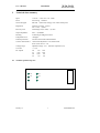
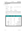
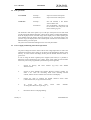
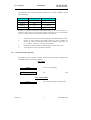
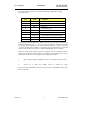
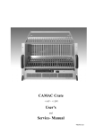
W-Ie–Ne-R
UEP10M005 Power Supply
User’s Manual
UEP10M005-A0
General Remarks
The only purpose of this manual is a description of the product. It must not be interpreted a
declaration of conformity for this product including the product and software.
W-Ie-Ne-R revises this product and manual without notice. Differences of the description in
manual and product are possible.
W-Ie-Ne-R excludes completely any liability for loss of profits, loss of business, loss of use
or data, interrupt of business, or for indirect, special incidental, or consequential damages of
any kind, even if W-Ie-Ne-R has been advises of the possibility of such damages arising
from any defect or error in this manual or product.
Any use of the product which may influence health of human beings requires the express
written permission of W-Ie-Ne-R.
Products mentioned in this manual are mentioned for identification purposes only. Product
names appearing in this manual may or may not be registered trademarks or copyrights of
their respective companies.
No part of this product, including the product and the software may be reproduced,
transmitted, transcribed, stored in a retrieval system, or translated into any language in any
form by any means with the express written permission of W-Ie-Ne-R.
Kommentar [vH1]: Versionen
dieses Dokuments:
Wann
... [1]
January 13
i
UEP10M005-A0
Table of contents:
1
DESCRIPTION OF UEP10M005 .............................................................................................. 1
2
TECHNICAL DATA SUMMARY ............................................................................................ 1
2.1 TRIMMER POSITION TOP VIEW .................................................................................................... 1
3
OPERATING INSTRUCTIONS................................................................................................ 2
3.1 GLOBAL OPERATIONS ................................................................................................................ 2
3.2 FAN-OPERATIONS....................................................................................................................... 3
3.3 POWER-SUPPLY MONITORING AND CONTROL OPERATIONS ........................................................ 3
3.4 CAN-BUS INTERFACE OPERATION.............................................................................................. 4
3.5 ERROR MESSAGE LIST ................................................................................................................ 6
3.5.1 Run time error messages .................................................................................................. 7
4
PIN-ASSIGNMENT .................................................................................................................... 8
4.1
4.2
4.3
4.4
DC OUTPUT CONNECTOR
75 PIN ........................................................................................... 8
FAN CONNECTOR (EXT.) 15 PIN ............................................................................................. 8
MONITOR CONNECTOR 36 PIN ............................................................................................... 8
CANBUS-CONNECTORS > ITEM 3.4.......................................................................................... 8
January 13
ii
UEP10M005-A0
User’s Manual
UEP10M005
W-Ie–Ne-R
Plein & Baus GmbH
1
Description of UEP10M005
The W-Ie-Ne-R UEP10M005 is a linear regulated Power Supply for a special application.
Output voltages and load currents accord to the specification of the customer.
Mechanical construction fits into a 19” cabinet. The required height is 5 units plus1 unit for
air flow.
All switches, displays and fuses are located in the front of the unit. The mains plug, the dc
output plug, the external fan plug, the monitor plug and the CANbus plugs are mounted on
the rear.
Two fans are mounted inside the power supply to cool down the power transistors. It is very
important to provide a good airflow and to avoid any suppression of free air circulation.
The circuit is a classical one of a linear regulated power supply. The bipolar power transistor
are driven by a regulator circuit which contains the necessary elements such as references,
operational-amplifiers, small signal transistors and the required trimmers. These components
are accommodated on two similar boards each regulating one positive and one negative
voltage. An additional board provides control functions such as trip off, overload and
overtemperature.
The required dc-voltages are supplied by a mains transformer via rectifiers and electrolytic
capacitors
An additional auxiliary power supply drives the mains relay and soft start circuit.
A micro controller circuit is built in to achieve comfortable watching over the complete unit.
The display and switches in front, the internal- and external fans, the status of power supply,
the air temperature and the CANbus are serviced and controlled by this processor circuit.
The top- and bottom covers can be removed for access to internal components. Only
specially trained personal with the necessary equipment must maintain the power supply. For
access to the voltage trimmers the necessary holes in the top cover can be used. Severe
malfunction may result adjusting any other trimmer.
January 13
1
UEP10M005-A0
User’s Manual
UEP10M005
W-Ie–Ne-R
Plein & Baus GmbH
2
2.1
Technical data summary
Input
115VAC +10%/-15% 48 – 63Hz
Fuses
8A time lag 5x20mm
Noise and ripple
full load <0,6mV eff, 3mVpp, 1mV at 80% rated power
Regulation
load 10% to 100% <0,05%
line +/-10% <0,02%
Recovery time
load change 10% to 100% <0,15ms
Output impedance
static <0,2mOhm
Derating
no derating at 50degrees Celsius
Temperature error
<200ppm
Thermal protection
switches on heat sink and transformer
Current characteristics
current limit adjusted to 115% rated current
short circuit current <3A
Voltage-range
adjustment range >5% (attention: tripoff at 2,5%)
Crow bar
+/- 7,3V
DC outputs
U0
U1
U2
U3
+6V
-3,3V
+3,3V
-6V
32A
32A
8A
8A
Trimmer position top view
January 13
U0
U1
U2
U3
1
UEP10M005-A0
User’s Manual
W-Ie–Ne-R
UEP10M005
Plein & Baus GmbH
3
Operating Instructions
3.1
Global operations
POWER ON/OFF
switch up :
switch down :
on
off
(green POWER LED lights)
SYSRESET
not used
MODE SELECT
switch up :
next mode
switch down :
previous mode
On the alphanumeric display in the centre of the front panel the values of fan speed,
temperatures, voltages and currents as well as the adjusted voltage and current limits
will be shown. To choose between the available modes push the MODE SELECT
switch.
The following table gives a look about all available modes and shows examples for the
displayed values.
Mode
Voltage
Current
Description
reserved
reserved
+3V
3.30
2.00
+12V channel
-6V
6.00
2.00
-12V channel
+6V
6.00
30.0
+12V channel
-3V
3.30
30.0
+12V channel
FANS
3000
RPM
Fan Speed
PS TEMP
32
°C
power supply temp.
AIR TEMP
28
°C
fan air inlet temp.
POWER
150
W
total output power
CAENET
ADR
16
opt. CAENET interface addr.
CANBUS
ADR
1
opt. CAN interface addr.
SPEED
1
MBAUD
CAN: serial link speed
GENERAL CALL
127
January 13
CAN: general call address
2
UEP10M005-A0
User’s Manual
W-Ie–Ne-R
UEP10M005
Plein & Baus GmbH
3.2
Fan-operations
FAN SPEED
AUTO OFF
switch up :
step wise increase of fan speed
switch down :
step wise decrease of fan speed
switch up :
auto off enabled, a fan failure
will set off the crate
switch down :
auto off disabled, a fan failure will
not set off the crate, only local and
remote warning is given
The maximum value of fan speed is up to 3120 rpm. If the speed is lower than 3000
rpm the red SLOW SPEED LED lights. Change of fan speed is possible independently
from the displayed mode. If another range of the display was set before pushing the
FAN SPEED switch the display shows the speed for 5 sec. and returns back to the
previous range. The display shows the nominal speed of the blowers and twinkles if it
differs from the given real speed.
The yellow FAN FAILURE LED lights in the case of any fan-failure.
3.3
Power-supply monitoring and control operations
All present voltage and current values of the several voltage output lines as well as the
temperature inside the power supply can be shown on the alphanumeric display of the
fan-tray. To select between the display modes push the MODE SELECT switch as
given in 2.2.
In case of using the linear regulated power supplies (UEP series) it is possible to
define the current resolution for each voltage. These values which are stored within
the fan-tray unit can be programmed by the following switch algorithm,
1.
Switch on fan-tray and
SELECT switch.
2.
Switch up both POWER and MODE SELECT switches together for
about 5 sec. Then the controlling mode menu including selected
channel, and the current resolution will be shown on the display.
3.
Change the value by pushing the MODE SELECT switch down
(value will decrease) or up (value will increase).
4.
To
accept
the
new
value
To change the other limits repeat step 1 - 4.
5.
Disconnect mains to end programming.
January 13
select
3
channel
(e.g.+12V) with
switch
down
MODE
POWER.
UEP10M005-A0
User’s Manual
UEP10M005
W-Ie–Ne-R
Plein & Baus GmbH
The following table represents possible values for the current resolution and the
standard settings
Resolution
Full scale current
Default for channel
5mV/A
80A
+6V/-3,3V
10mV/A
40A
25mv/A
16A
50mV/A
8A
+3,3V/-6V
Further, it is possible to define the unit behavior after AC on or AC failure. It is
possible to select either a general crate is off after connecting to AC or an automatic
power on to allow the unit to switch automatically on after AC fail.
3.4
1.
Switch on fan-tray and select channel POWER with MODE SELECT switch.
2.
Switch up both POWER and MODE SELECT switches together for
about 5 sec. Then the controlling mode menu including „auto power on“
or “no auto” power on“ be shown on the display.
3.
Change the value by pushing the MODE SELECT switch down or up
4.
To accept the new value switch down POWER.
CAN-bus interface operation
If equipped with the optional CAN-bus interface the front panel is equipped with
additional elements for network operation:
SWITCHES
ADDR
CAN - bus crate address
LOCAL
not
used
LED - INDICATORS
LOCAL
January 13
green large LED lights if CAN Net OK
4
UEP10M005-A0
User’s Manual
W-Ie–Ne-R
UEP10M005
Plein & Baus GmbH
The 9-pin Sub-D connector for CAN-bus interfacing is prepared according
to CiA DS 102-1:
Pin
Line
Comment
1
-
2
CAN_L
3
GND
4
-
reserved by CiA
5
-
reserved by CiA
6
-
7
CAN_H
8
-
9
-
reserved by CiA
CAN_L bus line (dominant low)
Ground
CAN_H bus line (dominant high)
reserved by CiA (failure signal)
To change the CAN-bus address the ADDR switch has to be pressed. The address can
be selected within the range 1 ... 127. The chosen net address is displayed on the fan
tray display. If the display has been showing another parameter (voltage, fan speed,
...9 before changing the net address it will return to the previous display. To shut the
crate for remote control the position „CANBUS DISABLED“ has to be chosen.
Within the W-Ie-Ne-R CAN-bus protocol a broadcast call to all connected crates is
possible (see CAN-BUS Interface report) . The address for this general call is factory
prepared 127 however it can be changed by the following procedure:
1.
Select display channel „GENERAL CALL“ with MODE SELECT switch.
2.
Switch
up
or down
the
ADDR
switch
to change
the
value.
If the crate has to be disabled for general call the position „GENERAL CALL OFF“
has to be selected.
January 13
5
UEP10M005-A0
User’s Manual
UEP10M005
W-Ie–Ne-R
Plein & Baus GmbH
According to the CAN bus specification the data transfer speed is depending on the
net length as given within the following table:
Max. Distance
Bit Rate
10 m
1.6 Mbit/s
40 m
1.0 Mbit/s
130 m
500 kbit/s
270 m
250 kit/s
530 m
125 kbit/s
620 m
100 kbit/s
1300 m
50 kbit/s
3300 m
20 kbit/s
6700 m
10 kbit/s
10.000 m
5kbit/s
Type
high- speed
low-speed
To adjust the net speed for a given net length select the bit rate according to this table
and set on the crates:
3.5
1.
Select display channel „SPEED“ with MODE SELECT switch.
2.
Switch up or down the ADDR switch to select the required rate.
Error message list
Both, W-Ie-Ne-R power supplies and fan-trays are equipped with micro-processor
based monitoring and control units. Thus, any fan or power module failure will be
detected and on the alphanumeric display an error message is shown. This is a useful
information for trouble shooting.
January 13
6
UEP10M005-A0
User’s Manual
W-Ie–Ne-R
UEP10M005
Plein & Baus GmbH
3.5.1 Error messages during self test after switching on
Unit failures
CHKS CONF
Configuration check sum error
CHKS UCAL
Check sum error of calibration voltage
CHKS ICAL
Check sum error of calibration current
PROM CONN
internal CPU error
CHKS ADDR
Check sum error of netware address
CHKS STAT
Check
status
CHKS FAN
Fan-tray check sum error
sum
error
of
previous
mains
on/off
3.5.1 Run time error messages
FAN OFF
Fan failure
TEMP OFF
Temperature of power supply too high
AC FAIL
Failure of ac power (line)
January 13
7
UEP10M005-A0
User’s Manual
W-Ie–Ne-R
UEP10M005
Plein & Baus GmbH
4
Pin-assignment
4.1
DC output connector
75 pin
4.2
U0
+6V/32A
Sense
39/40/41/42/66
29
U1
-3,3V/32A
Sense
47/48/49/50/67
30
U2
+3,3V/8A
Sense
55
31
U3
-6V/8A
Sense
57
32
Ground (Common)
Sense
43/44/45/51/52/53/56/58/60/63
26/27
PE (chassis ground)
65
Fan connector (ext.)
15 pin
+Ufan <24V 1/9
4.3
-Ufan Gnd.
2/10
Pulse Fan 1
3
Pulse Fan 2
4
Pulse Fan 3
5
Monitor connector
36 pin
4.4
Uo Monitor
3
Statusbit
23
U1 Monitor
4
Statusbit
11
U2 Monitor
2
Disable
28
U3 Monitor
5
Inhibit
26
Gnd analog
9
Power fail
12
Rearming +
35
Gnd digital
8
Rearming -
34
CANbus-Connectors > Item 3.4
January 13
8
UEP10M005-A0
Seite i: [1] Kommentar [vH1]
Dr. Lüder von Horn
Versionen dieses Dokuments:
Wann
Was
Wer
5. Juli 99
Manual erstellt
L. von Horn